EP2719604B1 - Système de sécurité dans un support de passager multifonction - Google Patents
Système de sécurité dans un support de passager multifonction Download PDFInfo
- Publication number
- EP2719604B1 EP2719604B1 EP12188528.9A EP12188528A EP2719604B1 EP 2719604 B1 EP2719604 B1 EP 2719604B1 EP 12188528 A EP12188528 A EP 12188528A EP 2719604 B1 EP2719604 B1 EP 2719604B1
- Authority
- EP
- European Patent Office
- Prior art keywords
- passenger carrier
- carrier
- blocking
- accessory
- passenger
- Prior art date
- Legal status (The legal status is an assumption and is not a legal conclusion. Google has not performed a legal analysis and makes no representation as to the accuracy of the status listed.)
- Not-in-force
Links
- 230000000903 blocking effect Effects 0.000 claims description 93
- 230000004913 activation Effects 0.000 claims description 10
- 230000009849 deactivation Effects 0.000 claims description 6
- 230000007246 mechanism Effects 0.000 description 13
- 230000008878 coupling Effects 0.000 description 7
- 238000010168 coupling process Methods 0.000 description 7
- 238000005859 coupling reaction Methods 0.000 description 7
- 239000000969 carrier Substances 0.000 description 5
- 238000010276 construction Methods 0.000 description 3
- 230000005484 gravity Effects 0.000 description 2
- 230000001960 triggered effect Effects 0.000 description 2
- 230000009471 action Effects 0.000 description 1
- 230000008901 benefit Effects 0.000 description 1
- 230000002779 inactivation Effects 0.000 description 1
- 230000037431 insertion Effects 0.000 description 1
- 238000003780 insertion Methods 0.000 description 1
- 230000003472 neutralizing effect Effects 0.000 description 1
- 238000009877 rendering Methods 0.000 description 1
- 230000004044 response Effects 0.000 description 1
Images


Classifications
-
- B—PERFORMING OPERATIONS; TRANSPORTING
- B62—LAND VEHICLES FOR TRAVELLING OTHERWISE THAN ON RAILS
- B62B—HAND-PROPELLED VEHICLES, e.g. HAND CARTS OR PERAMBULATORS; SLEDGES
- B62B7/00—Carriages for children; Perambulators, e.g. dolls' perambulators
- B62B7/04—Carriages for children; Perambulators, e.g. dolls' perambulators having more than one wheel axis; Steering devices therefor
- B62B7/12—Carriages for children; Perambulators, e.g. dolls' perambulators having more than one wheel axis; Steering devices therefor convertible, e.g. into children's furniture or toy
- B62B7/126—Carriages for children; Perambulators, e.g. dolls' perambulators having more than one wheel axis; Steering devices therefor convertible, e.g. into children's furniture or toy into a trailer, e.g. bicycle trailer
-
- B—PERFORMING OPERATIONS; TRANSPORTING
- B62—LAND VEHICLES FOR TRAVELLING OTHERWISE THAN ON RAILS
- B62B—HAND-PROPELLED VEHICLES, e.g. HAND CARTS OR PERAMBULATORS; SLEDGES
- B62B5/00—Accessories or details specially adapted for hand carts
- B62B5/06—Hand moving equipment, e.g. handle bars
- B62B5/064—Hand moving equipment, e.g. handle bars adaptable for different users, e.g. by means of pivoting elements
-
- B—PERFORMING OPERATIONS; TRANSPORTING
- B62—LAND VEHICLES FOR TRAVELLING OTHERWISE THAN ON RAILS
- B62B—HAND-PROPELLED VEHICLES, e.g. HAND CARTS OR PERAMBULATORS; SLEDGES
- B62B5/00—Accessories or details specially adapted for hand carts
- B62B5/08—Children's seats ; Seats or supports for other persons
- B62B5/082—Children's seats
-
- B—PERFORMING OPERATIONS; TRANSPORTING
- B62—LAND VEHICLES FOR TRAVELLING OTHERWISE THAN ON RAILS
- B62B—HAND-PROPELLED VEHICLES, e.g. HAND CARTS OR PERAMBULATORS; SLEDGES
- B62B7/00—Carriages for children; Perambulators, e.g. dolls' perambulators
- B62B7/04—Carriages for children; Perambulators, e.g. dolls' perambulators having more than one wheel axis; Steering devices therefor
- B62B7/14—Carriages for children; Perambulators, e.g. dolls' perambulators having more than one wheel axis; Steering devices therefor with detachable or rotatably-mounted body
- B62B7/145—Carriages for children; Perambulators, e.g. dolls' perambulators having more than one wheel axis; Steering devices therefor with detachable or rotatably-mounted body the body being a rigid seat, e.g. a shell
-
- B—PERFORMING OPERATIONS; TRANSPORTING
- B62—LAND VEHICLES FOR TRAVELLING OTHERWISE THAN ON RAILS
- B62B—HAND-PROPELLED VEHICLES, e.g. HAND CARTS OR PERAMBULATORS; SLEDGES
- B62B9/00—Accessories or details specially adapted for children's carriages or perambulators
- B62B9/005—Safety means for traffic, e.g. lights, reflectors, mirrors etc.
-
- B—PERFORMING OPERATIONS; TRANSPORTING
- B62—LAND VEHICLES FOR TRAVELLING OTHERWISE THAN ON RAILS
- B62B—HAND-PROPELLED VEHICLES, e.g. HAND CARTS OR PERAMBULATORS; SLEDGES
- B62B9/00—Accessories or details specially adapted for children's carriages or perambulators
- B62B9/10—Perambulator bodies; Equipment therefor
- B62B9/12—Perambulator bodies; Equipment therefor involving parts that are adjustable, attachable or detachable
-
- B—PERFORMING OPERATIONS; TRANSPORTING
- B62—LAND VEHICLES FOR TRAVELLING OTHERWISE THAN ON RAILS
- B62B—HAND-PROPELLED VEHICLES, e.g. HAND CARTS OR PERAMBULATORS; SLEDGES
- B62B9/00—Accessories or details specially adapted for children's carriages or perambulators
- B62B9/24—Safety guards for children, e.g. harness
-
- B—PERFORMING OPERATIONS; TRANSPORTING
- B62—LAND VEHICLES FOR TRAVELLING OTHERWISE THAN ON RAILS
- B62B—HAND-PROPELLED VEHICLES, e.g. HAND CARTS OR PERAMBULATORS; SLEDGES
- B62B9/00—Accessories or details specially adapted for children's carriages or perambulators
- B62B9/28—Auxiliary dismountable seats ; Additional platforms for children in standing-up position
-
- B—PERFORMING OPERATIONS; TRANSPORTING
- B62—LAND VEHICLES FOR TRAVELLING OTHERWISE THAN ON RAILS
- B62K—CYCLES; CYCLE FRAMES; CYCLE STEERING DEVICES; RIDER-OPERATED TERMINAL CONTROLS SPECIALLY ADAPTED FOR CYCLES; CYCLE AXLE SUSPENSIONS; CYCLE SIDE-CARS, FORECARS, OR THE LIKE
- B62K13/00—Cycles convertible to, or transformable into, other types of cycles or land vehicle
-
- B—PERFORMING OPERATIONS; TRANSPORTING
- B62—LAND VEHICLES FOR TRAVELLING OTHERWISE THAN ON RAILS
- B62K—CYCLES; CYCLE FRAMES; CYCLE STEERING DEVICES; RIDER-OPERATED TERMINAL CONTROLS SPECIALLY ADAPTED FOR CYCLES; CYCLE AXLE SUSPENSIONS; CYCLE SIDE-CARS, FORECARS, OR THE LIKE
- B62K17/00—Cycles not otherwise provided for
-
- B—PERFORMING OPERATIONS; TRANSPORTING
- B62—LAND VEHICLES FOR TRAVELLING OTHERWISE THAN ON RAILS
- B62K—CYCLES; CYCLE FRAMES; CYCLE STEERING DEVICES; RIDER-OPERATED TERMINAL CONTROLS SPECIALLY ADAPTED FOR CYCLES; CYCLE AXLE SUSPENSIONS; CYCLE SIDE-CARS, FORECARS, OR THE LIKE
- B62K27/00—Sidecars; Forecars; Trailers or the like specially adapted to be attached to cycles
- B62K27/003—Trailers
-
- B—PERFORMING OPERATIONS; TRANSPORTING
- B62—LAND VEHICLES FOR TRAVELLING OTHERWISE THAN ON RAILS
- B62K—CYCLES; CYCLE FRAMES; CYCLE STEERING DEVICES; RIDER-OPERATED TERMINAL CONTROLS SPECIALLY ADAPTED FOR CYCLES; CYCLE AXLE SUSPENSIONS; CYCLE SIDE-CARS, FORECARS, OR THE LIKE
- B62K27/00—Sidecars; Forecars; Trailers or the like specially adapted to be attached to cycles
- B62K27/10—Other component parts or accessories
- B62K27/12—Coupling parts for attaching cars or the like to cycle; Arrangements thereof
-
- B—PERFORMING OPERATIONS; TRANSPORTING
- B62—LAND VEHICLES FOR TRAVELLING OTHERWISE THAN ON RAILS
- B62B—HAND-PROPELLED VEHICLES, e.g. HAND CARTS OR PERAMBULATORS; SLEDGES
- B62B2205/00—Hand-propelled vehicles or sledges being foldable or dismountable when not in use
- B62B2205/10—Detachable wheels
- B62B2205/104—Detachable wheel units, e.g. together with the wheel shaft
-
- B—PERFORMING OPERATIONS; TRANSPORTING
- B62—LAND VEHICLES FOR TRAVELLING OTHERWISE THAN ON RAILS
- B62B—HAND-PROPELLED VEHICLES, e.g. HAND CARTS OR PERAMBULATORS; SLEDGES
- B62B2301/00—Wheel arrangements; Steering; Stability; Wheel suspension
-
- B—PERFORMING OPERATIONS; TRANSPORTING
- B62—LAND VEHICLES FOR TRAVELLING OTHERWISE THAN ON RAILS
- B62B—HAND-PROPELLED VEHICLES, e.g. HAND CARTS OR PERAMBULATORS; SLEDGES
- B62B7/00—Carriages for children; Perambulators, e.g. dolls' perambulators
- B62B7/008—Carriages for children; Perambulators, e.g. dolls' perambulators for two or more children
-
- B—PERFORMING OPERATIONS; TRANSPORTING
- B62—LAND VEHICLES FOR TRAVELLING OTHERWISE THAN ON RAILS
- B62B—HAND-PROPELLED VEHICLES, e.g. HAND CARTS OR PERAMBULATORS; SLEDGES
- B62B7/00—Carriages for children; Perambulators, e.g. dolls' perambulators
- B62B7/04—Carriages for children; Perambulators, e.g. dolls' perambulators having more than one wheel axis; Steering devices therefor
- B62B7/044—Carriages for children; Perambulators, e.g. dolls' perambulators having more than one wheel axis; Steering devices therefor three wheeled
-
- B—PERFORMING OPERATIONS; TRANSPORTING
- B62—LAND VEHICLES FOR TRAVELLING OTHERWISE THAN ON RAILS
- B62B—HAND-PROPELLED VEHICLES, e.g. HAND CARTS OR PERAMBULATORS; SLEDGES
- B62B7/00—Carriages for children; Perambulators, e.g. dolls' perambulators
- B62B7/04—Carriages for children; Perambulators, e.g. dolls' perambulators having more than one wheel axis; Steering devices therefor
- B62B7/06—Carriages for children; Perambulators, e.g. dolls' perambulators having more than one wheel axis; Steering devices therefor collapsible or foldable
Definitions
- the invention pertains to a multi-function passenger carrier comprising a carrier frame and a passenger compartment within said carrier frame, said passenger carrier comprising first and second means for attaching a first and a second accessory to said carrier frame.
- Passenger carriers in particular child carriers of the stroller type, are commonly made foldable so that they can be easily converted into a compact and space-saving configuration for transport and storage.
- Multi-function passenger carriers are passenger carriers equipped to be used both as trailers that can be towed by a bicycle or other vehicle or by a skiing person and as manually pushed infant strollers.
- Combined strollers and bicycle trailers are disclosed in US 5,344,171 , US 0633,825 S , US 2008/0143076 A1 and US 2010/0244405 A1 .
- the trailer When decoupled from a bicycle, the trailer can be converted into a push-type carrier provided with a push-handle to allow the trailer to be pushed by a walking person in a manner corresponding to that of a conventional baby carrier or stroller.
- a stroller-type child carrier can be used in different ways also when in a stroller mode. Accordingly, the carrier can be used as a jogging stroller, a walking stroller or by a skiing person pushing the carrier.
- the carrier When using the carrier in a stroller mode, it is commonly desirable to equip the carrier with accessories that are coupled to the carrier frame in a position where the person pushing the carrier can readily reach the accessories.
- accessories include baby seats and other cargo holders which may carry a considerable weight and which when placed in an upper position on the frame may alter the center of gravity of the carrier.
- the altered center of gravity constitutes a particular problem when the carrier is used as a trailer, as the carrier will then be placed out of control and out of view behind the person pulling the carrier or riding the bicycle to which the carrier is coupled. In such situation a top-heavy carrier may accidentally overturn and the passenger or passengers may be harmed.
- a multi-function passenger carrier comprising a carrier frame and a passenger compartment within the carrier frame, the passenger carrier comprising first and second means for attaching a first and a second accessory to the carrier frame.
- the carrier frame comprises:
- the first and second means for attaching an accessory to the carrier frame cannot be used simultaneously.
- the first means for attaching an accessory is a holder for a drawbar for towing the carrier and the second means for attaching an accessory is a cargo holder
- use of the cargo holder will be prohibited when the carrier is coupled to a bicycle by means of the drawbar.
- the security arrangement of the invention is particularly useful when the passenger carrier is equipped to receive accessories that may be mutually excluding from a safety perspective.
- the first means for attaching an accessory to a part of a passenger carrier frame may be a means for attaching an accessory to a lower part of the passenger carrier frame and the second means for attaching an accessory to a passenger carrier frame may be a means for attaching an accessory to an upper part of the passenger carrier frame.
- first control means and the second control means on the passenger carrier interact in a bi-directional manner resulting in the second blocking arrangement on the passenger carrier frame being caused to be activated when the first blocking arrangement is inactivated. In this manner, activation of the first blocking arrangement leads to inactivation of the second blocking arrangement, and vice versa.
- the first means for attaching an accessory to the carrier frame may comprise a holder for a drawbar for pulling the passenger carrier by hand or after a vehicle such as a bicycle.
- the passenger carrier of the invention has a front portion and a rear portion in a longitudinal direction of the passenger carrier, an upper portion and a lower portion in a vertical direction of the passenger carrier and two side portions in a transverse direction of the passenger carrier.
- a holder for a drawbar may be arranged at the front portion of the passenger carrier and preferably at the lower portion of the passenger carrier.
- the holder may be placed centrally or at a side of the passenger carrier.
- Two or more holders may be provided in order to allow a user to choose a travel direction of the passenger carrier, to choose a central or lateral attachment point for the drawbar or to accommodate double-shafted drawbars.
- the individual holders may constitute first and second accessories which are provided with blocking arrangements to prevent simultaneous use of the holders, for instance if the holders are arranged at mutually excluding positions on the passenger carrier such as at the front and back part of the carrier.
- a holder for a drawbar may comprise a channel into which an end of the drawbar may be inserted and locked in the inserted position.
- the first blocking arrangement may comprise a blocking arm which is movable between an active blocking position with a portion of the blocking arm obstructing the channel in the holder and an inactive accessory receiving position wherein the blocking arm is located outside the channel in the holder.
- the active blocking position it is impossible to insert the end of a drawbar into the receiving channel in the holder and the passenger carrier cannot be used in a pulled mode either by manual pulling or by towing behind a vehicle.
- the inactive accessory receiving position the receiving channel is free from obstructions and the drawbar holder can be used for coupling of a drawbar to the passenger carrier.
- the second means for attaching an accessory to the carrier frame may comprise a cargo holder.
- the cargo holder may be a luggage holder, such as a bag holder or a child/baby seat holder.
- the cargo holder may be directly attached to the carrier frame either permanently or in a way to permit the cargo holder to be removed from the carrier frame.
- the cargo holder may be indirectly attached to the carrier frame via an accessory coupling arrangement.
- An example of a suitable accessory coupling arrangement is the accessory cross bar that is disclosed in European patent application No. 12176350.2 .
- the second blocking arrangement may act to block attachment of the cargo holder to the accessory coupling arrangement and/or to block attachment of the accessory, e.g. a baby seat, to the cargo holder.
- a cargo holder such as a baby seat may be arranged at the upper portion of the passenger carrier in order to allow a care-taker pushing the passenger carrier to have easy access to a child placed in the seat.
- a further advantage by placing a cargo holder at the upper portion of the passenger carrier, is that the carrier assumes a compact and space-saving configuration which makes it particularly suitable for use when walking in a city environment and when using public transportation.
- the passenger carrier is preferably provided with a push-handle that is connected to the carrier frame.
- the push-handle may be placed at the rear portion of the passenger carrier.
- Common push-handles have a generally horizontally arranged gripping portion which may be straight or curved and which is connected by two generally vertically arranged struts or legs at arranged at the sides of the passenger compartment.
- the passenger carrier may have one handle on each side of the passenger compartment or a combination of a loop-shaped push-handle and side handles.
- a further type of push-handle has only a single central strut to which a horizontal gripping bar is attached.
- the push-handle may be hingedly connected to the passenger carrier frame so that the angle and height of the gripping part may be adjusted.
- the push-handle may be arranged to assume at least two different positions in relation to the carrier frame.
- An adjustable push-handle of this type may be comprised in the second blocking arrangement and may be used in preventing direct or indirect attachment of a second accessory to the carrier frame such as to the upper part of the carrier frame.
- the push-handie may be arranged to be tilted into a position where it blocks or shields an accessory attachment site.
- the push-handle may be arranged to block attachment of the second accessory when the push-handle is in a forwardly tilted position on the carrier frame.
- the blocking arrangements may comprise locking means for locking the arrangements in a blocking position or configuration.
- the provision of locking means may be desired in order to prevent a user from over-riding the blocking function and return a blocking element such as a push-handle to a position where a second accessory can be mounted on the carrier frame simultaneously with a first accessory.
- the locking arrangement is preferably connected to the first and second control means acting on the first and second blocking arrangements and is arranged to come into action when the first blocking arrangement is inactive and the second blocking arrangement is active.
- locking means may be provided for locking the push-handle in the blocking position, such as a forwardly tilted blocking position.
- the locking means is preferably triggered by activation of the corresponding blocking arrangement.
- the locking means may be any type of locking mechanism as known in the art, such as snap-locks, locking pins etc.
- the locking means may be a spring-loaded locking pin that co-operates with a corresponding receiving member which may be a hole or cut-out in a hinge between the carrier frame and the push-handle. Tilting of the push-handle into the blocking position will then cause the locking pin to engage with the receiving member in the hinge and lock the push-handle in the blocking position.
- the connecting member connecting the first and second control means may be any type of connecting member allowing the first and second control means to be interconnected such that activation of one of the blocking arrangements causes the other blocking arrangement to be inactivated.
- Suitable connecting members comprise mechanical connectors such as levers, rods, wires, ropes and bands as well as electric connectors such as cables.
- a flexible elongated mechanical connecting element such as a wire, a rope or a band may be particularly preferred in a safety arrangement according to the invention.
- a flexible elongated connecting element may be threaded onto the carrier frame and may interact with parts of the carrier frame and with accessory attachment members on the carrier frame to selectively block one attachment site in a pair of attachment sites.
- the connecting element may be arranged to act on hinged and/or spring-loaded portions of the carrier frame when being pulled or tightened and may be arranged to assume a tightened position resulting in a first configuration of the carrier frame and/or one or more accessory attachment member and a relaxed position resulting in a distinctly different configuration of the carrier frame and/or one or more accessory attachment members.
- the carrier frame may comprise at least one hollow frame element and the flexible elongated element may be arranged within the at least one hollow frame element in the carrier frame.
- multi-function passenger carrier refers to a vehicle that can be used either as a trailer that is pulled or towed behind a vehicle such as a bicycle or manually pulled by a skiing or walking person, or as a push-carrier or stroller used by a person walking, running, jogging or skiing.
- a horizontal direction as used herein is implied a direction in a horizontal plane of a passenger carrier when in an in-use-position, i.e. while being pulled after a bicycle or being pushed by a person.
- a vertical direction as used herein is implied a direction in a vertical plane through a passenger carrier when in an in-use position, i.e. while being pulled after a bicycle or being pushed by a person.
- a front part of a passenger carrier or a carrier frame as used herein is implied a part that is intended to be facing forward in the travelling direction, either towards a bicycle if the passenger carrier is coupled to a bicycle, or to be facing away from a pusher of the passenger carrier when it is used as a push carrier.
- a back or rear part of a passenger carrier is a part opposite to the front part and is intended to be facing away from a bicycle or towards a person pushing the carrier depending on how the passenger carrier is being used.
- An upper part of a passenger carrier or carrier frame is a part facing upward, away from the ground when the passenger carrier is in an In-use position.
- a lower part of a passenger carrier or carrier frame is a part facing downward towards the ground when the passenger carrier is in an in-use position.
- a travelling direction of a passenger carrier is a direction in which the passenger carrier is designed to be moved.
- the travelling direction corresponds to a longitudinal direction of the passenger carrier, and is perpendicular to the transverse direction and the height direction of the passenger carrier.
- Positional terms such as “upper”, “lower”, “underside”, etc. when used herein to describe the location of an element should be understood as referring to a passenger carrier when in a position for use as a trailer or a push-carrier. Positional terms are used in a corresponding way to describe the relative positioning of elements in a passenger carrier in an in-use position.
- a carrier frame as used herein is a structure comprising frame elements defining the general shape of the passenger carrier.
- the carrier frame includes the push-handle but not any wheels, passenger seats, covering, etc. or any removable equipment or accessories.
- the frame body is the part of the carrier frame surrounding the passenger space. The frame body does not include the push-handle.
- blocking arrangement should be understood in a broad sense as an arrangement that constitutes a hinder against proper mounting an accessory to the carrier frame.
- a blocking arrangement may include a part or parts that physically block or shield a mounting site to render it inaccessible for mounting of an accessory or may function by physically altering the configuration of a mounting site rendering it unsuitable for mounting of an accessory.
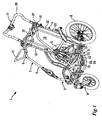
- the passenger carrier 1 in Fig. 1 is shown without any covering, revealing the structure of the passenger carrier frame 2.
- the passenger carrier 1 has a front part 3, a rear part 4, an upper part 5, a lower part 6 and two sides 7 as seen in Figs. 1 and 2 .
- the passenger carrier 1 is a multi-function passenger carrier that can be used in a trailer mode, e.g. coupled to the rear end of a bicycle and in a stroller mode allowing the carrier to be pushed by a walking or running person.
- the passenger carrier 1 in Fig. 1 is shown in the stroller mode, i.e. without any connection to a bicycle.
- the covering that is absent in Fig.
- the passenger carrier 1 comprises two rear wheels 8 mounted on a horizontal rear axis and a front wheel 9 pivotably mounted on the front portion 3 of the passenger carrier 1.
- the passenger carrier 1 When the passenger carrier 1 is in the trailer mode, it can be coupled to the rear end of a bicycle by means of a drawbar holder 10 arranged at the front portion 3 of the passenger carrier 1.
- the drawbar holder 10 is shown to be positioned low on a side of the front portion 3 of the carrier frame 2.
- a drawbar holder may also be placed on the opposite side of the carrier frame 2 or at any other suitable location on the carrier frame 2.
- the passenger carrier 1 shown in Figs. 1 and 2 can be folded into a compact transport and storage configuration by folding the passenger carrier frame 2 at lockable pivot joints. Foldability is generally a desired feature of a passenger carrier but is not an essential feature of the passenger carrier 1 according to the invention and will not be further described herein.
- the passenger carrier frame 2 further comprises a central push-handle 11 at the rear portion 4 of the passenger carrier frame 2.
- the push-handle 11 has a generally horizontally arranged gripping portion and forms an arch-like connection between two generally vertically arranged hollow side struts 12 extending from the upper portion 5 of the passenger carrier 1 to the lower portion 6 of the passenger carrier 1 at each side of a passenger carrier compartment 13 located inside the passenger carrier frame 2.
- the push-handle 11 is connected to the remaining carrier frame 2 by hinges 14 allowing the angle and height of the push-handle 11 to be adjusted.
- the push-handle 11 is arranged to assume at least two different positions in relation to the carrier frame 2 corresponding to the stroller mode and the trailer mode of the passenger carrier 1.
- Figs. 1 and 2 The specific shape and construction of the push-handle that is shown in Figs. 1 and 2 should not be considered to be limiting to the invention, as many other shapes may be envisaged by a person skilled in the art such as a pair of non-connected handles or a handle arranged on a single central supporting rod. Furthermore, it is to be understood that the shape and construction of the carrier frame 2 may be different from that shown in Fig. 1 . For instance, the shape of the passenger compartment may be different; the passenger carrier may have two front wheels, etc.
- the passenger carrier 1 in Fig. 1 is shown in a stroller mode and is suitable for being pushed by a person moving behind or at a side of the passenger carrier 1 and gripping the push-handle 11.
- the passenger carrier 1 in Fig. 1 is equipped with a cargo holder 15 which is adapted to receive and hold a baby seat in a position corresponding to that shown in Fig. 5 .
- the passenger carrier of the invention may be provided with any type of cargo holder such as bags, baskets, cargo plates, trays, etc. and should not be considered limited to the baby seat holder shown in the figures.
- the cargo holder may be directly attached to the carrier frame either permanently or in a way to permit the cargo holder to be removed from the carrier frame.
- the cargo holder is shown to be indirectly attached to the carrier frame 2 via an accessory coupling arrangement in the form of an accessory cross bar 16 of the type disclosed in European patent application No. 12176350.2 .
- the passenger carrier 1 is shown in a trailer mode allowing it to be pulled or towed by means of a first accessory 20 constituted by a towbar that is attached to the drawbar holder 10 by being inserted through an opening 21 in the front end of the drawbar holder 10 into a receiving channel 22 inside the drawbar holder.
- a first accessory 20 constituted by a towbar that is attached to the drawbar holder 10 by being inserted through an opening 21 in the front end of the drawbar holder 10 into a receiving channel 22 inside the drawbar holder.
- the front wheel 9 has been removed from the carrier frame 2.
- Alternative ways of adapting the carrier to better suit being pulled as a trailer include folding away one or more front wheels on the underside of the carrier. The manner of neutralizing the front wheel or front wheels which is chosen is not critical to the invention.
- the passenger carrier 1 in Fig. 2 is further shown with the cargo holder 15 removed from the accessory cross bar 16 and with the push-handle 11 tilted in a forward position in over the upper portion 5 of the passenger carrier 1.
- the drawbar holder 10 comprises an internal first blocking arrangement 23 and a first control means 24 for controlling activation and deactivation of the first blocking arrangement 23.
- a connecting member 25 in the form of a connecting wire extends from the first control means 24 inside tubular hollow frame elements making up the carrier frame 2 such as inside the hoiiow side strut 12 extending from the rear wheel axis to the interior of the push-handle hinge 14.
- a second blocking arrangement 26 and a second control means 27 for controlling activation and deactivation of the second blocking arrangement 26 are arranged at the upper portion 5 of the passenger carrier 1.
- the second blocking arrangement 26 includes the push-handle 11 and the push-handle hinge 14.
- the second control means 27 is constituted by a mechanism inside the push-handle hinge 14 as will be described in the following in relation to Fig. 5 .
- the push-handle 11 When positioned as shown in Fig. 2 , the push-handle 11 is tilted into a position where it physically blocks access to the accessory cross bar 16, disabling attachment of a cargo holder 15 to the accessory cross bar 16 and indirectly disabling attachment of a baby seat, a bag or similar to the cargo holder 15.
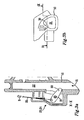
- the first blocking arrangement 23 which is arranged inside the housing of the drawbar holder 10 comprises a movable blocking arm 30.
- the blocking arm 30 is movable between the active blocking position shown in Figs. 3a and 3b with a portion of the blocking arm obstructing the drawbar receiving channel 22 in the holder 10 by protruding into the channel 22, and an inactive accessory receiving position wherein the blocking arm 30 is withdrawn from the channel 22 in the holder 10, allowing a drawbar 20 to be inserted into the channel 22.
- the blocking arm 30 is attached to a first end 25' of the connecting member 25 and is arranged to flip around a pivot axis 31 between the blocking position shown in Figs. 3a and 3b and the accessory receiving position shown in Figs. 4a and 4b in response to tensioning and relaxation of the connecting member 25. Accordingly, when the connecting member 25 is tensioned by being pulled in the blocking direction B, the tip of the blocking arm 30 will move into the drawbar receiving channel 22 and when the connecting member 25 is moved in the receiving direction R, the blocking arm 30 will move out of the drawbar receiving channel 22. In the blocking position, the connecting end of the drawbar 20 can be inserted into the drawbar receiving channel 22 through the opening 21 in the drawbar holder 10 as is shown in Figs. 4a and 4b .
- the second blocking arrangement 26 is controlled by the second control means 27 which is placed in the push-handle hinge 14 at a second end 25" of the connecting member 25 as shown in Fig. 5 .
- the second control means 27 includes a compressible spring 31 and a spring actuating member 32, which will cause the spring 31 to be compressed as the push-handle 11 is moved in a forward direction F and the connecting member 25 moves in a direction R which is the release direction R for the first control means 23 in the drawbar holder 10. This means that simultaneously with moving the push-handle 11 into the forward-tilted blocking position disabling mounting of a cargo holder 15, as best shown in Fig.
- the connecting member 25 will move the blocking arm 30 in the drawbar holder 10 into the drawbar receiving position, enabling attachment of a drawbar 20 in the drawbar holder 10.
- a cargo holder 15 can be mounted on the accessory cross bar 16 while attachment of a drawbar in the drawbar holder is prohibited.
- the mechanism in the push-handle hinge 14 further includes a locking mechanism 35.
- the locking mechanism 35 in the push-handle hinge 14 is triggered by activation of the second blocking arrangement 26.
- the locking means consists of a spring-loaded locking pin 36 which is actuated by a wedge-shaped member 37 and which co-operates with a corresponding receiving member 37 which is indicated as a hole inside the hinge mechanism. Tilting of the push-handle 11 into the blocking position causes the wedge-shaped member 37 to press the locking pin 36 into engagement with the receiving member 37 in the hinge 14 and lock the push-handle 11 in the blocking position.
- the locking mechanism 35 ascertains that there is no risk of inadvertently or intentionally over-riding the blocking of the accessory cross bar 16 while the drawbar holder is being used and constitutes an additional safety arrangement for preventing simultaneous use of two incompatible accessories.
- An additional safety arrangement in the form of a locking means is an optional feature of the invention.
- the blocking mechanisms for the drawbar holder 10 and the cargo holder 15 may be considered to be reciprocating mechanisms implying that when one blocking mechanism is activated, the other blocking mechanism is deactivated, as described herein.
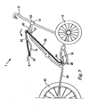
- Figs. 6 and 7 show a second embodiment of a multi-function passenger carrier 1 according to the invention.
- the passenger carrier 1 is shown from the side without any covering, and with the passenger carrier frame 2 and other components such as the wheels 9,10 and the push-handle 11 schematically illustrated.
- the passenger carrier 1 has a front part 3, a rear part 4, an upper part 5, a lower part 6 and two sides 7 as seen in Figs. 1 and 2 .
- the passenger carrier 1 is shown in the stroller mode in Fig. 6 and in the trailer mode in Fig. 7 .
- the passenger carrier 1 comprises two rear wheels 8 mounted on a horizontal rear axis and a front wheel 9 pivotably mounted on the front portion 3 of the passenger carrier 1. In the trailer mode shown in Fig.
- the passenger carrier 1 can be coupled to the rear end of a bicycle 40 by attaching a drawbar 20 in a drawbar holder 10 arranged at the front end 3 of the passenger carrier 1.
- the drawbar holder 10 is shown to be positioned on a lower portion of a side of the front portion 3 of the carrier frame 2 although other locations are conceivable within the scope of the invention.
- the drawbar holder 10 is similar to the drawbar holder 10 in Fig. 1 in that it has an inner drawbar receiving channel 22 and a forward opening 21 through which a drawbar 20 can be inserted into the drawbar receiving channel 22.
- the passenger carrier in Figs. 6 and 7 further comprises a cargo holder 15 in the form of a baby seat holder.
- the cargo holder 15 may be directly attached to the carrier frame 2 or may be indirectly attached by means of an adapter such as the accessory cross bar 16 shown in Fig. 1 .
- the cargo holder 15 comprises an upper part 41 and a lower part 42 which are connected by hinge means 43.
- a guiding loop 44 is arranged on the carrier frame 2 in front of the opening in the drawbar holder 10.
- a connecting member 25 in the form of a band is arranged with a first end 25' inserted through the guiding loop 44 and with a second end 25" attached to the upper part 41 of the cargo holder 15.
- the connecting member 25 is threaded through suitably placed guiding elements 45 on the outside of the carrier frame 2 from a first, remote side of the upper part 41 of the cargo holder 15, horizontally across the upper part 41 of the cargo holder 15 to a proximal side of the cargo holder 15 and down to the guiding loop 44 where the connecting member 25 terminates in a blocking rod 46.
- the terms "remote” and “proximal” refers to the location of the sides as perceived by a viewer of Figs. 6 and 7 .
- connecting member 25 is clearly visible in Figs. 6 and 7 , it is to be understood that it may be arranged in a less conspicuous manner when the passenger carrier is provided with a covering. Accordingly, the connecting member 25 may extend partially on the inside of the covering and/or in one or more channels arranged in the covering.
- the drawbar holder 10 constitutes a first means for attaching an accessory to a lower part of a passenger carrier frame 2 and the cargo holder 15 constitutes a first means for attaching an accessory to an upper part of a passenger carrier frame 2.
- the blocking rod 46 is shaped and sized to fit inside the drawbar receiving channel 22 in the drawbar holder 10 and is used to block insertion of a drawbar 20 into the drawbar receiving channel 22.
- the first blocking arrangement is provided by the blocking rod 46 which is controlled by the first end 25' of the connecting member 25 and the second blocking arrangement is provided by the hinge means 43 between the parts of the cargo holder 15 which is controlled by the connecting member 25.
- the security arrangement constituted by the first and second blocking arrangements in Figs. 6 and 7 has a simple and reliable construction.
- the blocking rod 46 is inserted into the drawbar receiving channel 22 and prevents the use of the passenger carrier as a trailer.
- the connecting member 25 is tensioned between the second end 25" at the upper part 41 of the cargo holder 15 and the drawbar holder 10 and keeps the upper part 41 of the cargo holder in a generally upwardly tilted attachment position.
- the blocking rod 46 is pulled out from the drawbar receiving channel 22 resulting in a slackening of the connecting member 25.
- the slackening of the connecting member 25 in turn triggers blocking of the cargo holder 15 by allowing the upper part 41 of the cargo holder 15 to tilt forward at the hinge means 43, thus altering the configuration of the cargo holder in a manner to make it impossible to attach a baby seat to the cargo holder 15.
Landscapes
- Engineering & Computer Science (AREA)
- Mechanical Engineering (AREA)
- Transportation (AREA)
- Chemical & Material Sciences (AREA)
- Combustion & Propulsion (AREA)
- Health & Medical Sciences (AREA)
- Public Health (AREA)
- Carriages For Children, Sleds, And Other Hand-Operated Vehicles (AREA)
- Handcart (AREA)
Claims (17)
- Support de passager multifonction (1), comprenant un bâti (2) et un compartiment pour passager (13) à l'intérieur dudit bâti (2), ledit support de passager (1) comprenant des premier et second moyens permettant de fixer un premier et un second accessoire sur ledit bâti (2), caractérisé en ce que ledit bâti (2) comprend un agencement de sécurité comprenant :- un premier agencement de blocage (23) permettant de bloquer la fixation dudit premier accessoire (20) sur ledit bâti (2),- un second agencement de blocage (26) permettant de bloquer la fixation dudit second accessoire (15) sur ledit bâti (2),- un premier moyen de commande (24) permettant de commander l'activation et la désactivation dudit premier agencement de blocage (23),- un second moyen de commande (27) permettant de commander l'activation et la désactivation dudit second agencement de blocage (26),- un élément de liaison (25) reliant ledit premier moyen de commande (24) audit second moyen de commande (27),lesdits premier et second moyens de commande (24, 27) étant agencés pour interagir par le biais dudit élément de liaison (25) pour entraîner l'activation dudit premier agencement de blocage (23) lorsque ledit second agencement de blocage (26) est inactivé.
- Support de passager multifonction selon la revendication 1, dans lequel ledit second agencement de blocage (26) est amené à être activé lorsque ledit premier agencement de blocage (23) est inactivé.
- Support de passager multifonction selon la revendication 1 ou 2, dans lequel ledit premier moyen permettant de fixer un accessoire sur une partie dudit bâti est un moyen permettant de fixer un accessoire sur une partie inférieure (6) dudit bâti (2) et ledit second moyen permettant de fixer un accessoire sur ledit bâti (2) est un moyen permettant de fixer un accessoire sur une partie supérieure (5) dudit bâti (2).
- Support de passager multifonction selon la revendication 1, 2 ou 3, dans lequel ledit premier moyen permettant de fixer un accessoire sur ledit bâti (2) comprend un support (10) pour une barre d'attelage (20).
- Support de passager multifonction selon la revendication 4, ledit support de passager (1) présentant une partie avant (3) et une partie arrière (4) dans un sens longitudinal, une partie supérieure (5) et une partie inférieure (6) dans un sens vertical et deux parties latérales (7) dans un sens transversal, ledit support (10) étant agencé sur ladite partie avant (3) dudit support de passager (1) et de préférence sur ladite partie inférieure (6) dudit support de passager (1).
- Support de passager multifonction selon la revendication 4 ou 5, dans lequel ledit support (10) comprend un canal (22) destiné à l'insertion d'une extrémité de ladite barre d'attelage (20).
- Support de passager multifonction selon la revendication 6, dans lequel ledit premier agencement de blocage (23) comprend un bras de blocage qui est susceptible de passer d'une position active de blocage, dans laquelle une partie dudit bras de blocage obstrue ledit canal (22) présent dans ledit support (10), à une position inactive de réception d'accessoire dans laquelle ledit bras de blocage est complètement retiré dudit canal (22) présent dans ledit support (10).
- Support de passager multifonction selon l'une quelconque des revendications précédentes, dans lequel ledit second moyen permettant de fixer un accessoire sur ledit bâti (2) comprend un support de charge (15).
- Support de passager multifonction selon la revendication 8, dans lequel ledit support de charge (15) est un support pour siège de bébé.
- Support de passager multifonction selon la revendication 8 ou 9, ledit support de passager (1) présentant une partie avant (3) et une partie arrière (4) dans un sens longitudinal, une partie supérieure (5) et une partie inférieure (6) dans un sens vertical et deux parties latérales (7) dans un sens transversal, ledit support de charge (15) étant agencé sur ladite partie supérieure (5) dudit support de passager (1).
- Support de passager multifonction selon l'une quelconque des revendications précédentes, dans lequel une poignée de poussée (11) est reliée audit bâti (2).
- Support de passager multifonction selon la revendication 11, dans lequel ladite poignée de poussée (11) est reliée de manière articulée audit bâti (2) et est agencée pour adopter au moins deux positions différentes par rapport audit bâti (2).
- Support de passager multifonction selon la revendication 12, dans lequel ladite poignée de poussée (11) est comprise dans ledit second agencement de blocage (26).
- Support de passager multifonction selon la revendication 13, dans lequel ladite poignée de poussée (11) est agencée pour bloquer la fixation dudit second accessoire lorsque ladite poignée de poussée (11) se trouve dans une position inclinée vers l'avant sur ledit bâti (2).
- Support de passager multifonction selon la revendication 14, dans lequel ledit second agencement de blocage comprend un moyen permettant de verrouiller ladite poignée de poussée (11) dans ladite position inclinée vers l'avant.
- Support de passager multifonction selon l'une quelconque des revendications précédentes, dans lequel ledit élément de liaison (25) comprend un élément allongé flexible tel qu'un fil métallique, une cordelette ou un ruban.
- Support de passager multifonction selon la revendication 15, dans lequel ledit bâti (2) comprend au moins un élément de bâti creux (12) et ledit élément allongé flexible est agencé à l'intérieur dudit au moins un élément de bâti creux (12).
Priority Applications (5)
| Application Number | Priority Date | Filing Date | Title |
|---|---|---|---|
| EP12188528.9A EP2719604B1 (fr) | 2012-10-15 | 2012-10-15 | Système de sécurité dans un support de passager multifonction |
| US14/428,237 US9315206B2 (en) | 2012-10-15 | 2013-10-09 | Security arrangement in a multi-function passenger carrier |
| PCT/CA2013/050760 WO2014059538A1 (fr) | 2012-10-15 | 2013-10-09 | Agencement de sécurité dans un support de passager multifonctionnel |
| CN201390000810.6U CN205034194U (zh) | 2012-10-15 | 2013-10-09 | 多功能乘客承载器 |
| CA2887609A CA2887609C (fr) | 2012-10-15 | 2013-10-09 | Agencement de securite dans un support de passager multifonctionnel |
Applications Claiming Priority (1)
| Application Number | Priority Date | Filing Date | Title |
|---|---|---|---|
| EP12188528.9A EP2719604B1 (fr) | 2012-10-15 | 2012-10-15 | Système de sécurité dans un support de passager multifonction |
Publications (2)
| Publication Number | Publication Date |
|---|---|
| EP2719604A1 EP2719604A1 (fr) | 2014-04-16 |
| EP2719604B1 true EP2719604B1 (fr) | 2015-12-09 |
Family
ID=47018086
Family Applications (1)
| Application Number | Title | Priority Date | Filing Date |
|---|---|---|---|
| EP12188528.9A Not-in-force EP2719604B1 (fr) | 2012-10-15 | 2012-10-15 | Système de sécurité dans un support de passager multifonction |
Country Status (5)
| Country | Link |
|---|---|
| US (1) | US9315206B2 (fr) |
| EP (1) | EP2719604B1 (fr) |
| CN (1) | CN205034194U (fr) |
| CA (1) | CA2887609C (fr) |
| WO (1) | WO2014059538A1 (fr) |
Families Citing this family (11)
| Publication number | Priority date | Publication date | Assignee | Title |
|---|---|---|---|---|
| FR3003801B1 (fr) * | 2013-03-28 | 2017-02-17 | Dorel France Sa | Poussette pour enfant transformable en remorque pour velo |
| CA2969082C (fr) * | 2014-11-26 | 2021-11-16 | Thule Canada Inc. | Mecanismes de verrouillage d'accessoire de vehicule de transport |
| USD793914S1 (en) * | 2016-05-20 | 2017-08-08 | Thule Canada Inc. | Stroller |
| CN107128416B (zh) * | 2017-06-02 | 2022-11-18 | 应世海 | 多功能折叠三轮电动车 |
| KR101894460B1 (ko) * | 2018-04-10 | 2018-09-04 | 김미진 | 사용 편의성을 향상시킨 유모차 |
| KR102031279B1 (ko) * | 2018-04-18 | 2019-10-11 | 유상진 | 유모차 |
| US11142278B2 (en) * | 2018-09-01 | 2021-10-12 | Matthijs van Leeuwen | Tow arm assembly to detachably attach a trailer to a bicycle |
| JP7709447B2 (ja) | 2020-01-29 | 2025-07-16 | グアバ ファミリー インコーポレイテッド | コンパクトなたたみ込みおよびサスペンションシステムを有するベビーカー |
| DE202021100743U1 (de) * | 2021-02-15 | 2022-05-18 | Cybex Gmbh | Kindertransporteinrichtungs-System |
| KR102415226B1 (ko) | 2021-11-15 | 2022-06-29 | 최예진 | 사용 편의성을 향상시킨 유아용 웨건 |
| CN223290917U (zh) * | 2022-04-18 | 2025-09-02 | 贝贝漫步有限责任公司 | 可转换婴儿车组合件 |
Family Cites Families (35)
| Publication number | Priority date | Publication date | Assignee | Title |
|---|---|---|---|---|
| US3887208A (en) * | 1974-01-18 | 1975-06-03 | Paul Vidal | Collapsible and portable utility cart |
| US4759559A (en) * | 1986-08-08 | 1988-07-26 | Moulton Lee A | Multiple use article carrier |
| US5308096A (en) * | 1990-11-26 | 1994-05-03 | Kid Around Kinetica Inc. | Bicycle trailer |
| US5344171A (en) | 1991-10-22 | 1994-09-06 | Garforth Bles Timothy | Wheeled vehicle for carriage of children convertible between jogging and bicycle trailer configurations |
| US5267744A (en) * | 1992-05-14 | 1993-12-07 | Burley Design Cooperative | Stroller wheel assembly for bicycle trailer |
| US5421597A (en) * | 1992-12-18 | 1995-06-06 | Tri Industries, Inc. | Convertible infant stroller and trailer with quick release hitch |
| US5259634A (en) * | 1992-12-18 | 1993-11-09 | Tri Industries, Inc. | Convertible infant stroller and trailer |
| US5431478A (en) * | 1993-03-22 | 1995-07-11 | Noonan; Mark | Convertible baby carrier |
| US5599033A (en) * | 1993-08-30 | 1997-02-04 | Tri Industries, Inc. | Convertible trailer and jogging stroller for two children |
| US5988670A (en) * | 1995-02-15 | 1999-11-23 | Jiangsu Goodbaby Group, Inc. | Child carrier |
| US5791670A (en) * | 1995-02-16 | 1998-08-11 | Hunker; David B. | Article carrying device |
| US5641173A (en) * | 1995-04-20 | 1997-06-24 | Cobb, Jr.; William T. | Cycling trailer |
| US5695208A (en) * | 1995-09-19 | 1997-12-09 | Racing Strollers, Inc. | Baby stroller conversion assembly |
| US6056306A (en) * | 1996-04-09 | 2000-05-02 | Instep, Llc | Foldable compact molded stroller and trailer with flexible hitch |
| US5758889A (en) * | 1996-06-21 | 1998-06-02 | Ledakis; Sherry L. | Mobile people carrier with adjustable wind screen |
| US5941600A (en) * | 1996-11-14 | 1999-08-24 | Chrysler Corporation | Method and apparatus for mounting articles to a vehicle floor |
| SE511162C2 (sv) * | 1996-11-26 | 1999-08-16 | Volvo Ab | Anordning för frigörbar fasthållning av föremål vid en mobil enhet |
| US5975549A (en) * | 1997-01-30 | 1999-11-02 | Ockenden; Lynn Marie | System for simultaneously mounting a plurality of bicycle accessories to a bicycle frame |
| US6554307B1 (en) * | 1998-07-31 | 2003-04-29 | Transbike Systems, Inc. | Bicycle dropout frame member |
| US6155582A (en) * | 1998-09-29 | 2000-12-05 | Bourbeau; Charle | Bicycle coupling device |
| US6581945B1 (en) * | 1999-03-17 | 2003-06-24 | Richard N. Shapiro | Collapsible compact carrier device with collapsible wheel construction |
| AU2001263238A1 (en) * | 2000-05-19 | 2001-12-03 | Yakima Products, Inc. | Bicycle child carrier trailer |
| EP1217635A3 (fr) | 2000-12-22 | 2004-09-15 | Heraeus Electro-Nite International N.V. | Résistance électrique de platin ou une composition de platine et arrangement sensorique |
| US7017940B2 (en) * | 2002-02-05 | 2006-03-28 | Mark Hatfull | Board carrier |
| US6976685B1 (en) * | 2002-02-15 | 2005-12-20 | Samsonite Corporation | Wheeled car seat |
| US6623021B1 (en) * | 2002-03-19 | 2003-09-23 | Edward Scott Nelson | Automated bicycle steering lock |
| US7073859B1 (en) * | 2004-08-19 | 2006-07-11 | Pamela S. Wilson | Pivotable child seat for use in a vehicle |
| US7172206B2 (en) * | 2004-11-22 | 2007-02-06 | Jeff Staszak | Folding bicycle trailer |
| US7011320B1 (en) * | 2005-02-14 | 2006-03-14 | Ramon Gomez | Motorcycle carriage |
| US7547029B2 (en) * | 2006-09-14 | 2009-06-16 | 634182 Alberta Ltd. | Child transport vehicle |
| US7766359B2 (en) | 2006-09-27 | 2010-08-03 | Leighton Klevana | Trailer/jogger combination |
| EP2225146B1 (fr) | 2007-11-30 | 2012-03-07 | Imad Assaf | Vehicule de transport leger |
| USD633825S1 (en) | 2008-01-03 | 2011-03-08 | Montare LLC | Pet bicycle trailer and stroller |
| US7992889B2 (en) * | 2008-08-08 | 2011-08-09 | Soma Cycle, Inc. | Convertible stroller-cycle |
| DE102009044840A1 (de) * | 2009-12-09 | 2011-06-16 | Clean Mobile Ag | Mehrfachkinderwagen mit Sitzbereichen für mindestens zwei Kinder |
-
2012
- 2012-10-15 EP EP12188528.9A patent/EP2719604B1/fr not_active Not-in-force
-
2013
- 2013-10-09 CN CN201390000810.6U patent/CN205034194U/zh not_active Expired - Fee Related
- 2013-10-09 US US14/428,237 patent/US9315206B2/en not_active Expired - Fee Related
- 2013-10-09 CA CA2887609A patent/CA2887609C/fr not_active Expired - Fee Related
- 2013-10-09 WO PCT/CA2013/050760 patent/WO2014059538A1/fr not_active Ceased
Also Published As
| Publication number | Publication date |
|---|---|
| US20150232115A1 (en) | 2015-08-20 |
| CN205034194U (zh) | 2016-02-17 |
| US9315206B2 (en) | 2016-04-19 |
| CA2887609A1 (fr) | 2014-04-24 |
| EP2719604A1 (fr) | 2014-04-16 |
| CA2887609C (fr) | 2016-12-13 |
| WO2014059538A1 (fr) | 2014-04-24 |
Similar Documents
| Publication | Publication Date | Title |
|---|---|---|
| EP2719604B1 (fr) | Système de sécurité dans un support de passager multifonction | |
| US9545941B2 (en) | Infant stroller apparatus | |
| CN105189251B (zh) | 可转化成自行车拖车的用于儿童的手推童车 | |
| US8157286B2 (en) | Stroller | |
| KR102285917B1 (ko) | 유모차 부속물, 및 유모차와 그러한 부속물을 포함하는 운송 어셈블리 | |
| US20070235966A1 (en) | Stroller with Removable Arm Bar | |
| US10293843B2 (en) | Juvenile stroller | |
| AU2016295637A1 (en) | Cargo cycle with passenger seats | |
| US6854744B2 (en) | Lightweight convertible car seat and stroller | |
| US20130313874A1 (en) | Child safety seat for vehicles | |
| US11691691B2 (en) | Bike trailer | |
| CN112046592A (zh) | 可折叠框架组件和婴孩车 | |
| KR20210121165A (ko) | 어린이 안전 시트 조립체 | |
| US20170072983A1 (en) | Collapsible pushchair frame or doll's pushchair frame | |
| AU2011101394A4 (en) | A Stroller Frame with an Angle Adjustable Second Seat | |
| US8678424B2 (en) | Bicycle trailor front wheel arrangement | |
| JP2025536610A (ja) | 係合台アセンブリおよびホイール式移動装置 | |
| CN121712384A (zh) | 枢转封围部可折叠收容装置 | |
| AU2011101476A4 (en) | A stroller frame with a connecting mechanism for detachably installing a second seat | |
| TWI921695B (zh) | 卡座組件及輪式移動裝置 | |
| CN223786843U (zh) | 载具固定机构 | |
| GB2374323A (en) | A cart with an adjustable link member | |
| CN223864730U (zh) | 儿童安全座椅 | |
| ITMI20130704A1 (it) | Seggiolino per bambini per veicoli |
Legal Events
| Date | Code | Title | Description |
|---|---|---|---|
| PUAI | Public reference made under article 153(3) epc to a published international application that has entered the european phase |
Free format text: ORIGINAL CODE: 0009012 |
|
| AK | Designated contracting states |
Kind code of ref document: A1 Designated state(s): AL AT BE BG CH CY CZ DE DK EE ES FI FR GB GR HR HU IE IS IT LI LT LU LV MC MK MT NL NO PL PT RO RS SE SI SK SM TR |
|
| AX | Request for extension of the european patent |
Extension state: BA ME |
|
| 17P | Request for examination filed |
Effective date: 20141006 |
|
| RBV | Designated contracting states (corrected) |
Designated state(s): AL AT BE BG CH CY CZ DE DK EE ES FI FR GB GR HR HU IE IS IT LI LT LU LV MC MK MT NL NO PL PT RO RS SE SI SK SM TR |
|
| RIC1 | Information provided on ipc code assigned before grant |
Ipc: B62K 17/00 20060101ALI20150309BHEP Ipc: B62B 9/24 20060101ALI20150309BHEP Ipc: B62B 7/04 20060101ALI20150309BHEP Ipc: B62B 9/00 20060101ALI20150309BHEP Ipc: B62B 7/06 20060101ALI20150309BHEP Ipc: B62B 9/12 20060101ALI20150309BHEP Ipc: B62B 7/12 20060101AFI20150309BHEP Ipc: B62K 27/00 20060101ALI20150309BHEP Ipc: B62B 7/00 20060101ALI20150309BHEP Ipc: B62B 9/28 20060101ALI20150309BHEP Ipc: B62K 13/00 20060101ALI20150309BHEP |
|
| GRAP | Despatch of communication of intention to grant a patent |
Free format text: ORIGINAL CODE: EPIDOSNIGR1 |
|
| INTG | Intention to grant announced |
Effective date: 20150413 |
|
| INTG | Intention to grant announced |
Effective date: 20150417 |
|
| GRAP | Despatch of communication of intention to grant a patent |
Free format text: ORIGINAL CODE: EPIDOSNIGR1 |
|
| INTG | Intention to grant announced |
Effective date: 20150720 |
|
| GRAS | Grant fee paid |
Free format text: ORIGINAL CODE: EPIDOSNIGR3 |
|
| GRAA | (expected) grant |
Free format text: ORIGINAL CODE: 0009210 |
|
| AK | Designated contracting states |
Kind code of ref document: B1 Designated state(s): AL AT BE BG CH CY CZ DE DK EE ES FI FR GB GR HR HU IE IS IT LI LT LU LV MC MK MT NL NO PL PT RO RS SE SI SK SM TR |
|
| REG | Reference to a national code |
Ref country code: GB Ref legal event code: FG4D |
|
| REG | Reference to a national code |
Ref country code: AT Ref legal event code: REF Ref document number: 764436 Country of ref document: AT Kind code of ref document: T Effective date: 20151215 Ref country code: CH Ref legal event code: EP |
|
| REG | Reference to a national code |
Ref country code: IE Ref legal event code: FG4D |
|
| REG | Reference to a national code |
Ref country code: DE Ref legal event code: R096 Ref document number: 602012012846 Country of ref document: DE |
|
| REG | Reference to a national code |
Ref country code: SE Ref legal event code: TRGR |
|
| REG | Reference to a national code |
Ref country code: NL Ref legal event code: FP |
|
| REG | Reference to a national code |
Ref country code: LT Ref legal event code: MG4D |
|
| PG25 | Lapsed in a contracting state [announced via postgrant information from national office to epo] |
Ref country code: ES Free format text: LAPSE BECAUSE OF FAILURE TO SUBMIT A TRANSLATION OF THE DESCRIPTION OR TO PAY THE FEE WITHIN THE PRESCRIBED TIME-LIMIT Effective date: 20151209 Ref country code: NO Free format text: LAPSE BECAUSE OF FAILURE TO SUBMIT A TRANSLATION OF THE DESCRIPTION OR TO PAY THE FEE WITHIN THE PRESCRIBED TIME-LIMIT Effective date: 20160309 Ref country code: LT Free format text: LAPSE BECAUSE OF FAILURE TO SUBMIT A TRANSLATION OF THE DESCRIPTION OR TO PAY THE FEE WITHIN THE PRESCRIBED TIME-LIMIT Effective date: 20151209 |
|
| REG | Reference to a national code |
Ref country code: AT Ref legal event code: MK05 Ref document number: 764436 Country of ref document: AT Kind code of ref document: T Effective date: 20151209 |
|
| PG25 | Lapsed in a contracting state [announced via postgrant information from national office to epo] |
Ref country code: FI Free format text: LAPSE BECAUSE OF FAILURE TO SUBMIT A TRANSLATION OF THE DESCRIPTION OR TO PAY THE FEE WITHIN THE PRESCRIBED TIME-LIMIT Effective date: 20151209 Ref country code: RS Free format text: LAPSE BECAUSE OF FAILURE TO SUBMIT A TRANSLATION OF THE DESCRIPTION OR TO PAY THE FEE WITHIN THE PRESCRIBED TIME-LIMIT Effective date: 20151209 Ref country code: LV Free format text: LAPSE BECAUSE OF FAILURE TO SUBMIT A TRANSLATION OF THE DESCRIPTION OR TO PAY THE FEE WITHIN THE PRESCRIBED TIME-LIMIT Effective date: 20151209 Ref country code: GR Free format text: LAPSE BECAUSE OF FAILURE TO SUBMIT A TRANSLATION OF THE DESCRIPTION OR TO PAY THE FEE WITHIN THE PRESCRIBED TIME-LIMIT Effective date: 20160310 |
|
| PG25 | Lapsed in a contracting state [announced via postgrant information from national office to epo] |
Ref country code: IS Free format text: LAPSE BECAUSE OF FAILURE TO SUBMIT A TRANSLATION OF THE DESCRIPTION OR TO PAY THE FEE WITHIN THE PRESCRIBED TIME-LIMIT Effective date: 20151209 |
|
| PG25 | Lapsed in a contracting state [announced via postgrant information from national office to epo] |
Ref country code: CZ Free format text: LAPSE BECAUSE OF FAILURE TO SUBMIT A TRANSLATION OF THE DESCRIPTION OR TO PAY THE FEE WITHIN THE PRESCRIBED TIME-LIMIT Effective date: 20151209 Ref country code: IT Free format text: LAPSE BECAUSE OF FAILURE TO SUBMIT A TRANSLATION OF THE DESCRIPTION OR TO PAY THE FEE WITHIN THE PRESCRIBED TIME-LIMIT Effective date: 20151209 |
|
| PG25 | Lapsed in a contracting state [announced via postgrant information from national office to epo] |
Ref country code: AT Free format text: LAPSE BECAUSE OF FAILURE TO SUBMIT A TRANSLATION OF THE DESCRIPTION OR TO PAY THE FEE WITHIN THE PRESCRIBED TIME-LIMIT Effective date: 20151209 Ref country code: SM Free format text: LAPSE BECAUSE OF FAILURE TO SUBMIT A TRANSLATION OF THE DESCRIPTION OR TO PAY THE FEE WITHIN THE PRESCRIBED TIME-LIMIT Effective date: 20151209 Ref country code: SK Free format text: LAPSE BECAUSE OF FAILURE TO SUBMIT A TRANSLATION OF THE DESCRIPTION OR TO PAY THE FEE WITHIN THE PRESCRIBED TIME-LIMIT Effective date: 20151209 Ref country code: EE Free format text: LAPSE BECAUSE OF FAILURE TO SUBMIT A TRANSLATION OF THE DESCRIPTION OR TO PAY THE FEE WITHIN THE PRESCRIBED TIME-LIMIT Effective date: 20151209 Ref country code: RO Free format text: LAPSE BECAUSE OF FAILURE TO SUBMIT A TRANSLATION OF THE DESCRIPTION OR TO PAY THE FEE WITHIN THE PRESCRIBED TIME-LIMIT Effective date: 20151209 Ref country code: PT Free format text: LAPSE BECAUSE OF FAILURE TO SUBMIT A TRANSLATION OF THE DESCRIPTION OR TO PAY THE FEE WITHIN THE PRESCRIBED TIME-LIMIT Effective date: 20160411 Ref country code: IS Free format text: LAPSE BECAUSE OF FAILURE TO SUBMIT A TRANSLATION OF THE DESCRIPTION OR TO PAY THE FEE WITHIN THE PRESCRIBED TIME-LIMIT Effective date: 20160409 |
|
| REG | Reference to a national code |
Ref country code: DE Ref legal event code: R097 Ref document number: 602012012846 Country of ref document: DE |
|
| PLBE | No opposition filed within time limit |
Free format text: ORIGINAL CODE: 0009261 |
|
| STAA | Information on the status of an ep patent application or granted ep patent |
Free format text: STATUS: NO OPPOSITION FILED WITHIN TIME LIMIT |
|
| PG25 | Lapsed in a contracting state [announced via postgrant information from national office to epo] |
Ref country code: DK Free format text: LAPSE BECAUSE OF FAILURE TO SUBMIT A TRANSLATION OF THE DESCRIPTION OR TO PAY THE FEE WITHIN THE PRESCRIBED TIME-LIMIT Effective date: 20151209 Ref country code: PL Free format text: LAPSE BECAUSE OF FAILURE TO SUBMIT A TRANSLATION OF THE DESCRIPTION OR TO PAY THE FEE WITHIN THE PRESCRIBED TIME-LIMIT Effective date: 20151209 |
|
| 26N | No opposition filed |
Effective date: 20160912 |
|
| PG25 | Lapsed in a contracting state [announced via postgrant information from national office to epo] |
Ref country code: SI Free format text: LAPSE BECAUSE OF FAILURE TO SUBMIT A TRANSLATION OF THE DESCRIPTION OR TO PAY THE FEE WITHIN THE PRESCRIBED TIME-LIMIT Effective date: 20151209 |
|
| PG25 | Lapsed in a contracting state [announced via postgrant information from national office to epo] |
Ref country code: BE Free format text: LAPSE BECAUSE OF FAILURE TO SUBMIT A TRANSLATION OF THE DESCRIPTION OR TO PAY THE FEE WITHIN THE PRESCRIBED TIME-LIMIT Effective date: 20151209 |
|
| REG | Reference to a national code |
Ref country code: CH Ref legal event code: PL |
|
| GBPC | Gb: european patent ceased through non-payment of renewal fee |
Effective date: 20161015 |
|
| REG | Reference to a national code |
Ref country code: IE Ref legal event code: MM4A |
|
| REG | Reference to a national code |
Ref country code: FR Ref legal event code: ST Effective date: 20170630 |
|
| PG25 | Lapsed in a contracting state [announced via postgrant information from national office to epo] |
Ref country code: GB Free format text: LAPSE BECAUSE OF NON-PAYMENT OF DUE FEES Effective date: 20161015 Ref country code: LI Free format text: LAPSE BECAUSE OF NON-PAYMENT OF DUE FEES Effective date: 20161031 Ref country code: CH Free format text: LAPSE BECAUSE OF NON-PAYMENT OF DUE FEES Effective date: 20161031 Ref country code: FR Free format text: LAPSE BECAUSE OF NON-PAYMENT OF DUE FEES Effective date: 20161102 |
|
| PG25 | Lapsed in a contracting state [announced via postgrant information from national office to epo] |
Ref country code: LU Free format text: LAPSE BECAUSE OF NON-PAYMENT OF DUE FEES Effective date: 20161015 |
|
| PG25 | Lapsed in a contracting state [announced via postgrant information from national office to epo] |
Ref country code: IE Free format text: LAPSE BECAUSE OF NON-PAYMENT OF DUE FEES Effective date: 20161015 |
|
| PG25 | Lapsed in a contracting state [announced via postgrant information from national office to epo] |
Ref country code: CY Free format text: LAPSE BECAUSE OF FAILURE TO SUBMIT A TRANSLATION OF THE DESCRIPTION OR TO PAY THE FEE WITHIN THE PRESCRIBED TIME-LIMIT Effective date: 20151209 Ref country code: HU Free format text: LAPSE BECAUSE OF FAILURE TO SUBMIT A TRANSLATION OF THE DESCRIPTION OR TO PAY THE FEE WITHIN THE PRESCRIBED TIME-LIMIT; INVALID AB INITIO Effective date: 20121015 |
|
| PG25 | Lapsed in a contracting state [announced via postgrant information from national office to epo] |
Ref country code: MT Free format text: LAPSE BECAUSE OF NON-PAYMENT OF DUE FEES Effective date: 20161031 Ref country code: HR Free format text: LAPSE BECAUSE OF FAILURE TO SUBMIT A TRANSLATION OF THE DESCRIPTION OR TO PAY THE FEE WITHIN THE PRESCRIBED TIME-LIMIT Effective date: 20151209 Ref country code: MC Free format text: LAPSE BECAUSE OF FAILURE TO SUBMIT A TRANSLATION OF THE DESCRIPTION OR TO PAY THE FEE WITHIN THE PRESCRIBED TIME-LIMIT Effective date: 20151209 Ref country code: MK Free format text: LAPSE BECAUSE OF FAILURE TO SUBMIT A TRANSLATION OF THE DESCRIPTION OR TO PAY THE FEE WITHIN THE PRESCRIBED TIME-LIMIT Effective date: 20151209 |
|
| PG25 | Lapsed in a contracting state [announced via postgrant information from national office to epo] |
Ref country code: BG Free format text: LAPSE BECAUSE OF FAILURE TO SUBMIT A TRANSLATION OF THE DESCRIPTION OR TO PAY THE FEE WITHIN THE PRESCRIBED TIME-LIMIT Effective date: 20151209 |
|
| PG25 | Lapsed in a contracting state [announced via postgrant information from national office to epo] |
Ref country code: AL Free format text: LAPSE BECAUSE OF FAILURE TO SUBMIT A TRANSLATION OF THE DESCRIPTION OR TO PAY THE FEE WITHIN THE PRESCRIBED TIME-LIMIT Effective date: 20151209 Ref country code: TR Free format text: LAPSE BECAUSE OF FAILURE TO SUBMIT A TRANSLATION OF THE DESCRIPTION OR TO PAY THE FEE WITHIN THE PRESCRIBED TIME-LIMIT Effective date: 20151209 |
|
| PGFP | Annual fee paid to national office [announced via postgrant information from national office to epo] |
Ref country code: NL Payment date: 20181017 Year of fee payment: 7 |
|
| PGFP | Annual fee paid to national office [announced via postgrant information from national office to epo] |
Ref country code: SE Payment date: 20181011 Year of fee payment: 7 Ref country code: DE Payment date: 20181002 Year of fee payment: 7 |
|
| REG | Reference to a national code |
Ref country code: DE Ref legal event code: R119 Ref document number: 602012012846 Country of ref document: DE |
|
| REG | Reference to a national code |
Ref country code: NL Ref legal event code: MM Effective date: 20191101 |
|
| PG25 | Lapsed in a contracting state [announced via postgrant information from national office to epo] |
Ref country code: DE Free format text: LAPSE BECAUSE OF NON-PAYMENT OF DUE FEES Effective date: 20200501 |
|
| PG25 | Lapsed in a contracting state [announced via postgrant information from national office to epo] |
Ref country code: SE Free format text: LAPSE BECAUSE OF NON-PAYMENT OF DUE FEES Effective date: 20191016 Ref country code: NL Free format text: LAPSE BECAUSE OF NON-PAYMENT OF DUE FEES Effective date: 20191101 |
|
| P01 | Opt-out of the competence of the unified patent court (upc) registered |
Effective date: 20230528 |