EP2721191B1 - Appareil et procédé d'infiltration de vapeur chimique - Google Patents
Appareil et procédé d'infiltration de vapeur chimique Download PDFInfo
- Publication number
- EP2721191B1 EP2721191B1 EP12728162.4A EP12728162A EP2721191B1 EP 2721191 B1 EP2721191 B1 EP 2721191B1 EP 12728162 A EP12728162 A EP 12728162A EP 2721191 B1 EP2721191 B1 EP 2721191B1
- Authority
- EP
- European Patent Office
- Prior art keywords
- reaction chamber
- gas
- chamber
- tantalum
- vacuum
- Prior art date
- Legal status (The legal status is an assumption and is not a legal conclusion. Google has not performed a legal analysis and makes no representation as to the accuracy of the status listed.)
- Active
Links
Images


Classifications
-
- A—HUMAN NECESSITIES
- A61—MEDICAL OR VETERINARY SCIENCE; HYGIENE
- A61F—FILTERS IMPLANTABLE INTO BLOOD VESSELS; PROSTHESES; DEVICES PROVIDING PATENCY TO, OR PREVENTING COLLAPSING OF, TUBULAR STRUCTURES OF THE BODY, e.g. STENTS; ORTHOPAEDIC, NURSING OR CONTRACEPTIVE DEVICES; FOMENTATION; TREATMENT OR PROTECTION OF EYES OR EARS; BANDAGES, DRESSINGS OR ABSORBENT PADS; FIRST-AID KITS
- A61F2/00—Filters implantable into blood vessels; Prostheses, i.e. artificial substitutes or replacements for parts of the body; Appliances for connecting them with the body; Devices providing patency to, or preventing collapsing of, tubular structures of the body, e.g. stents
- A61F2/02—Prostheses implantable into the body
- A61F2/30—Joints
- A61F2/3094—Designing or manufacturing processes
-
- C—CHEMISTRY; METALLURGY
- C23—COATING METALLIC MATERIAL; COATING MATERIAL WITH METALLIC MATERIAL; CHEMICAL SURFACE TREATMENT; DIFFUSION TREATMENT OF METALLIC MATERIAL; COATING BY VACUUM EVAPORATION, BY SPUTTERING, BY ION IMPLANTATION OR BY CHEMICAL VAPOUR DEPOSITION, IN GENERAL; INHIBITING CORROSION OF METALLIC MATERIAL OR INCRUSTATION IN GENERAL
- C23C—COATING METALLIC MATERIAL; COATING MATERIAL WITH METALLIC MATERIAL; SURFACE TREATMENT OF METALLIC MATERIAL BY DIFFUSION INTO THE SURFACE, BY CHEMICAL CONVERSION OR SUBSTITUTION; COATING BY VACUUM EVAPORATION, BY SPUTTERING, BY ION IMPLANTATION OR BY CHEMICAL VAPOUR DEPOSITION, IN GENERAL
- C23C16/00—Chemical coating by decomposition of gaseous compounds, without leaving reaction products of surface material in the coating, i.e. chemical vapour deposition [CVD] processes
- C23C16/04—Coating on selected surface areas, e.g. using masks
- C23C16/045—Coating cavities or hollow spaces, e.g. interior of tubes; Infiltration of porous substrates
-
- C—CHEMISTRY; METALLURGY
- C23—COATING METALLIC MATERIAL; COATING MATERIAL WITH METALLIC MATERIAL; CHEMICAL SURFACE TREATMENT; DIFFUSION TREATMENT OF METALLIC MATERIAL; COATING BY VACUUM EVAPORATION, BY SPUTTERING, BY ION IMPLANTATION OR BY CHEMICAL VAPOUR DEPOSITION, IN GENERAL; INHIBITING CORROSION OF METALLIC MATERIAL OR INCRUSTATION IN GENERAL
- C23C—COATING METALLIC MATERIAL; COATING MATERIAL WITH METALLIC MATERIAL; SURFACE TREATMENT OF METALLIC MATERIAL BY DIFFUSION INTO THE SURFACE, BY CHEMICAL CONVERSION OR SUBSTITUTION; COATING BY VACUUM EVAPORATION, BY SPUTTERING, BY ION IMPLANTATION OR BY CHEMICAL VAPOUR DEPOSITION, IN GENERAL
- C23C16/00—Chemical coating by decomposition of gaseous compounds, without leaving reaction products of surface material in the coating, i.e. chemical vapour deposition [CVD] processes
- C23C16/06—Chemical coating by decomposition of gaseous compounds, without leaving reaction products of surface material in the coating, i.e. chemical vapour deposition [CVD] processes characterised by the deposition of metallic material
- C23C16/08—Chemical coating by decomposition of gaseous compounds, without leaving reaction products of surface material in the coating, i.e. chemical vapour deposition [CVD] processes characterised by the deposition of metallic material from metal halides
-
- C—CHEMISTRY; METALLURGY
- C23—COATING METALLIC MATERIAL; COATING MATERIAL WITH METALLIC MATERIAL; CHEMICAL SURFACE TREATMENT; DIFFUSION TREATMENT OF METALLIC MATERIAL; COATING BY VACUUM EVAPORATION, BY SPUTTERING, BY ION IMPLANTATION OR BY CHEMICAL VAPOUR DEPOSITION, IN GENERAL; INHIBITING CORROSION OF METALLIC MATERIAL OR INCRUSTATION IN GENERAL
- C23C—COATING METALLIC MATERIAL; COATING MATERIAL WITH METALLIC MATERIAL; SURFACE TREATMENT OF METALLIC MATERIAL BY DIFFUSION INTO THE SURFACE, BY CHEMICAL CONVERSION OR SUBSTITUTION; COATING BY VACUUM EVAPORATION, BY SPUTTERING, BY ION IMPLANTATION OR BY CHEMICAL VAPOUR DEPOSITION, IN GENERAL
- C23C16/00—Chemical coating by decomposition of gaseous compounds, without leaving reaction products of surface material in the coating, i.e. chemical vapour deposition [CVD] processes
- C23C16/44—Chemical coating by decomposition of gaseous compounds, without leaving reaction products of surface material in the coating, i.e. chemical vapour deposition [CVD] processes characterised by the method of coating
- C23C16/4401—Means for minimising impurities, e.g. dust, moisture or residual gas, in the reaction chamber
- C23C16/4405—Cleaning of reactor or parts inside the reactor by using reactive gases
-
- C—CHEMISTRY; METALLURGY
- C23—COATING METALLIC MATERIAL; COATING MATERIAL WITH METALLIC MATERIAL; CHEMICAL SURFACE TREATMENT; DIFFUSION TREATMENT OF METALLIC MATERIAL; COATING BY VACUUM EVAPORATION, BY SPUTTERING, BY ION IMPLANTATION OR BY CHEMICAL VAPOUR DEPOSITION, IN GENERAL; INHIBITING CORROSION OF METALLIC MATERIAL OR INCRUSTATION IN GENERAL
- C23C—COATING METALLIC MATERIAL; COATING MATERIAL WITH METALLIC MATERIAL; SURFACE TREATMENT OF METALLIC MATERIAL BY DIFFUSION INTO THE SURFACE, BY CHEMICAL CONVERSION OR SUBSTITUTION; COATING BY VACUUM EVAPORATION, BY SPUTTERING, BY ION IMPLANTATION OR BY CHEMICAL VAPOUR DEPOSITION, IN GENERAL
- C23C16/00—Chemical coating by decomposition of gaseous compounds, without leaving reaction products of surface material in the coating, i.e. chemical vapour deposition [CVD] processes
- C23C16/44—Chemical coating by decomposition of gaseous compounds, without leaving reaction products of surface material in the coating, i.e. chemical vapour deposition [CVD] processes characterised by the method of coating
- C23C16/455—Chemical coating by decomposition of gaseous compounds, without leaving reaction products of surface material in the coating, i.e. chemical vapour deposition [CVD] processes characterised by the method of coating characterised by the method used for introducing gases into reaction chamber or for modifying gas flows in reaction chamber
- C23C16/45557—Pulsed pressure or control pressure
-
- C—CHEMISTRY; METALLURGY
- C23—COATING METALLIC MATERIAL; COATING MATERIAL WITH METALLIC MATERIAL; CHEMICAL SURFACE TREATMENT; DIFFUSION TREATMENT OF METALLIC MATERIAL; COATING BY VACUUM EVAPORATION, BY SPUTTERING, BY ION IMPLANTATION OR BY CHEMICAL VAPOUR DEPOSITION, IN GENERAL; INHIBITING CORROSION OF METALLIC MATERIAL OR INCRUSTATION IN GENERAL
- C23C—COATING METALLIC MATERIAL; COATING MATERIAL WITH METALLIC MATERIAL; SURFACE TREATMENT OF METALLIC MATERIAL BY DIFFUSION INTO THE SURFACE, BY CHEMICAL CONVERSION OR SUBSTITUTION; COATING BY VACUUM EVAPORATION, BY SPUTTERING, BY ION IMPLANTATION OR BY CHEMICAL VAPOUR DEPOSITION, IN GENERAL
- C23C16/00—Chemical coating by decomposition of gaseous compounds, without leaving reaction products of surface material in the coating, i.e. chemical vapour deposition [CVD] processes
- C23C16/44—Chemical coating by decomposition of gaseous compounds, without leaving reaction products of surface material in the coating, i.e. chemical vapour deposition [CVD] processes characterised by the method of coating
- C23C16/458—Chemical coating by decomposition of gaseous compounds, without leaving reaction products of surface material in the coating, i.e. chemical vapour deposition [CVD] processes characterised by the method of coating characterised by the method used for supporting substrates in the reaction chamber
-
- A—HUMAN NECESSITIES
- A61—MEDICAL OR VETERINARY SCIENCE; HYGIENE
- A61F—FILTERS IMPLANTABLE INTO BLOOD VESSELS; PROSTHESES; DEVICES PROVIDING PATENCY TO, OR PREVENTING COLLAPSING OF, TUBULAR STRUCTURES OF THE BODY, e.g. STENTS; ORTHOPAEDIC, NURSING OR CONTRACEPTIVE DEVICES; FOMENTATION; TREATMENT OR PROTECTION OF EYES OR EARS; BANDAGES, DRESSINGS OR ABSORBENT PADS; FIRST-AID KITS
- A61F2/00—Filters implantable into blood vessels; Prostheses, i.e. artificial substitutes or replacements for parts of the body; Appliances for connecting them with the body; Devices providing patency to, or preventing collapsing of, tubular structures of the body, e.g. stents
- A61F2/02—Prostheses implantable into the body
- A61F2/28—Bones
-
- A—HUMAN NECESSITIES
- A61—MEDICAL OR VETERINARY SCIENCE; HYGIENE
- A61F—FILTERS IMPLANTABLE INTO BLOOD VESSELS; PROSTHESES; DEVICES PROVIDING PATENCY TO, OR PREVENTING COLLAPSING OF, TUBULAR STRUCTURES OF THE BODY, e.g. STENTS; ORTHOPAEDIC, NURSING OR CONTRACEPTIVE DEVICES; FOMENTATION; TREATMENT OR PROTECTION OF EYES OR EARS; BANDAGES, DRESSINGS OR ABSORBENT PADS; FIRST-AID KITS
- A61F2/00—Filters implantable into blood vessels; Prostheses, i.e. artificial substitutes or replacements for parts of the body; Appliances for connecting them with the body; Devices providing patency to, or preventing collapsing of, tubular structures of the body, e.g. stents
- A61F2/02—Prostheses implantable into the body
- A61F2/30—Joints
- A61F2/30767—Special external or bone-contacting surface, e.g. coating for improving bone ingrowth
-
- B—PERFORMING OPERATIONS; TRANSPORTING
- B22—CASTING; POWDER METALLURGY
- B22F—WORKING METALLIC POWDER; MANUFACTURE OF ARTICLES FROM METALLIC POWDER; MAKING METALLIC POWDER; APPARATUS OR DEVICES SPECIALLY ADAPTED FOR METALLIC POWDER
- B22F3/00—Manufacture of workpieces or articles from metallic powder characterised by the manner of compacting or sintering; Apparatus specially adapted therefor ; Presses and furnaces
- B22F3/12—Both compacting and sintering
- B22F3/14—Both compacting and sintering simultaneously
Definitions
- the present invention relates to improvements in chemical vapor infiltration (CVI) methods.
- the present invention relates to improvements in a CVI apparatus and process for depositing a biocompatible material onto a porous substrate.
- Orthopedic implants may be constructed of, or coated with, porous biomaterial to encourage bone growth into the implant.
- porous biomaterial is a porous tantalum metal or metal alloy produced using Trabecular Metal TM technology generally available from Zimmer, Inc., of Warsaw, Indiana.
- Trabecular Metal TM is a trademark of Zimmer, Inc.
- This porous material may be formed of a reticulated vitreous carbon (RVC) bone-like substrate which is infiltrated and coated with a biocompatible material, such as tantalum, in the manner disclosed in U.S. Patent No.
- RVC reticulated vitreous carbon
- the resulting coated material is lightweight, strong, and has an open-cell structure that is similar to the structure of natural cancellous bone, thereby providing a matrix into which cancellous bone may grow to fix the orthopedic implant to the patient's bone.
- US 2010/094430 to Krumdieck relates to an implant having an outer porous surface and a ceramic material applied to the surface utilising pulsed pressure metal organic chemical vapour deposition.
- the starting material for the porous tantalum material is an open-cell polymer foam block or sheet.
- This polymer foam material is converted into the RVC substrate by first impregnating the polymer foam with a carbonaceous resin and then heating the impregnated foam to a suitable pyrolysis temperature, on the order of 800° C - 2000° C, to convert the polymer foam and any carbonaceous resin into vitreous carbon having individual carbon foam ligaments.
- the RVC may be shaped into the final form of the orthopedic implant using machining or other shaping techniques. Using CVI, a biocompatible material, such as tantalum, niobium, tungsten, or alloys thereof, may then be coated onto the RVC substrates in a heated reaction chamber.
- tantalum metal In order to deposit tantalum onto the RVC substrates, solid tantalum metal (Ta) is heated to react with chlorine gas (Cl 2 ) to form tantalum chloride gas, such as tantalum pentachloride (TaCl 5 ), for example.
- the tantalum chloride gas flows into the reaction chamber and is mixed with hydrogen gas (H2).
- H2 hydrogen gas
- tantalum metal deposits onto the substrates in a thin film over the individual ligaments of the substrates and the hydrogen and chlorine gases react to form hydrogen chloride gas (HCl), which is exhausted from the reaction chamber: Equation 1 TaCl 5 + 5/2 H 2 ⁇ Ta + 5 HCl
- Equation 2 Equation 2 2 HCl (g) + 2 TaCl 5(g) + H 2 O (1) + 12 NaOH (aq) ⁇ Ta 2 O 5(s) + 12 NaCl (aq) + 8 H 2 O (1)
- the present disclosure relates to improvements in a CVI apparatus and process for depositing a biocompatible material onto a porous substrate to form an orthopedic implant.
- the substrate may be formed of RVC foam and coated with tantalum, niobium, tungsten, or other biocompatible materials.
- the present invention provides, a method as claimed in claim 1 for operating a chemical vapor infiltration apparatus to produce an orthopedic implant.
- the method includes the steps of: placing a porous substrate into a reaction chamber of the chemical vapor infiltration apparatus, the reaction chamber defined by an upper end, a lower end and a cylindrical side wall extending between the upper and lower end; exposing the porous substrate to a first gas and a second gas in the reaction chamber, the first gas flowing upwardly into the reaction chamber and the second gas flowing downwardly into the reaction chamber; wherein the first and second gases react in the reaction chamber to deposit a biocompatible metal onto the porous substrate; and varying a vacuum level in the reaction chamber during the exposing step.
- the present invention provides a chemical vapor infiltration apparatus as claimed in claim 12.
- the apparatus includes: a reaction chamber having a first gas input for receiving a first gas and a second gas input for receiving a second gas, the reaction chamber defined by an upper end, a lower end and a cylindrical side wall, extending between the upper and lower end, a first gas and a second gas, wherein the first gas flows upwardly into the chamber and the second gas flows downwardly into the reaction chamber, the first and second gases reacting to form a biocompatible metal; a shelving unit in the reaction chamber that is sized to hold a plurality of porous substrates in a stacked arrangement, the biocompatible metal depositing onto the plurality of substrates and an actuator configured to rotate the shelving unit and the plurality of porous substrates on the shelving unit relative to the reaction chamber.
- the apparatus may include a reactor design in which the gas flow is homogenized within a deposition chamber of the apparatus.
- the apparatus may include a reactor design with a variable temperature profile.
- the apparatus may include a reactor designed to rapidly cool the reaction chamber after a CVI cycle.
- the apparatus may include a reactor designed to self-clean after a CVI cycle.
- the CVI apparatus may include a reactor design in which the tantalum source is supported below the substrates.
- the apparatus may include a reactor design with an adjustable vacuum..
- a single apparatus may include multiple or all of the above-described features.
- a single apparatus may include a tantalum source supported below the substrates, an adjustable vacuum, a homogenized gas flow, a variable temperature profile, a rapid cooling cycle, and a self-cleaning cycle.
- the method includes the steps of: placing a porous substrate into a reaction chamber of the chemical vapor infiltration apparatus; depositing a first portion of a biocompatible metal onto the porous substrate to produce the orthopedic implant, and a second portion of the biocompatible metal onto the reaction chamber; and cleaning the reaction chamber by heating the reaction chamber and injecting a chlorine stripping gas into the heated reaction chamber, the chlorine stripping gas reacting with the second portion of the biocompatible metal to remove the second portion of the biocompatible metal from the reaction chamber.
- Exemplary methods, processing steps, and devices for improving CVI are provided herein.
- CVD chemical vapor deposition
- an illustrative embodiment CVI apparatus 10 is used to deposit tantalum onto one or more substrates 100, which are illustratively comprised of RVC foam.
- Other biocompatible materials such as niobium and tungsten, may be deposited onto the substrates 100 or other similar porous materials.
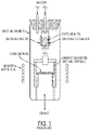
- FIG. 2 is a schematic view of the apparatus 10, and it is understood that the design of the apparatus 10 may vary.
- the apparatus 10 is positioned on a table 1 and includes a housing 12, illustratively made of glass, that surrounds an internal reaction chamber 14, which is made of graphite or other conductive materials.
- the apparatus 10 includes a chlorine gas (Cl 2 ) input 16, shown in Fig. 3 , as well as a hydrogen gas (H 2 ) input 17, and an air input 19 into the reaction chamber 14.
- the apparatus 10 also includes an exhaust gas output 18 from the reaction chamber 14 and a vacuum system 20. Additionally, the reaction chamber 14 is operably coupled to at least one heat source, such as induction coils 22, 24 ( FIG. 3 ).
- the apparatus 10 includes a heated chlorination chamber 26 and a heated deposition chamber 28 or furnace.
- a supply of tantalum or another biocompatible metal is associated with the chlorination chamber 26 and the substrates 100 are located within the deposition chamber 28.
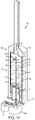
- the substrates 100 may include a bulk quantity of material in the form of a block or sheet; however, as shown in FIG. 3 , exemplary substrates 100 include a plurality of individual components that have been formed into the shape of orthopedic implants, such as acetabular cups.
- the illustrative reaction chamber 14 is defined by an upper end 30, a lower end 32, and a substantially cylindrical side wall 34 extending therebetween and along a longitudinal axis l.
- An inner surface 36 of the side wall 34 defines a longitudinal length of the reaction chamber 14.
- the substrates 100 are positioned within the deposition chamber 28 and may be supported on an internal structure, such as a plate 40 or shelving unit 42.
- the plate 40 and shelving unit 42 may be configured to support the substrates 100 in a stacked arrangement, as shown in FIG. 3 .
- the shelving unit 42 may resemble a tree and includes a plurality of shelves 46 extending radially outwardly from a central post 44 to support the substrates 100. Further details of the plate 40 will be explained below.
- the post 44 extends along the longitudinal length of the deposition chamber 28.
- the CVI process and apparatus 10 may be configured to facilitate adjustment of certain processing parameters, such as time, temperature, gas flow rates, and vacuum levels. To determine the effect of varying these parameters, and in order to improve the CVI process, deposition efficiency and weight variance are measured. Deposition efficiency is a process output that determines the percentage of tantalum that successfully deposits onto the substrates 100 during one CVI cycle, as is shown in Equation 3 below.
- the tantalum source is the amount of tantalum that is converted from the solid to gaseous state and flows from the chlorination chamber 26 to the deposition chamber 28.
- Deposition efficiency compares the amount of tantalum source to the amount of tantalum actually deposited on a given substrate (i.e., the amount of gaseous tantalum in the deposition chamber 28 that reacts with a given substrate 100 and deposits thereon).
- Deposition Efficiency Ta deposited / Ta source
- Deposition rate in contrast to deposition efficiency, is the rate at which tantalum is deposited onto the substrates 100. If tantalum is deposited onto the substrates 100 too rapidly, the tantalum may not effectively infiltrate the pores (not shown) of the substrates 100 and therefore may be thicker and non-uniform on the exterior of the substrates 100 but thinner on the internal ligaments of the substrates 100.
- Deposition efficiency and weight variance affect the number of CVI cycles that must be performed in order to uniformly coat each substrate component 100. Therefore, by decreasing the weight variance and increasing the deposition efficiency, the overall time required to produce a porous tantalum implant decreases because fewer CVI cycles are needed to form a uniform tantalum coating on the substrates 100. Additionally, improvements in weight variance and deposition efficiency may eliminate some processing steps, such as rearranging the substrates 100 after each CVI cycle in order to deposit a uniform tantalum coating onto the substrates 100.
- the CVI apparatus 10 includes a reactor design in which the tantalum source is supported below the substrates 100.
- the apparatus 10 includes a reactor design with an adjustable vacuum 20.
- the apparatus 10 includes a reactor design in which the gas flow is homogenized within the deposition chamber 28.
- a further illustrative embodiment of the apparatus 10 includes a reactor design with a variable temperature profile in the deposition chamber 28.
- another illustrative embodiment of the apparatus 10 includes a reactor design configured to rapidly cool the reaction chamber 14 after a CVI cycle.
- solid tantalum in the form of nuggets or other scrap tantalum, within a holding device of a chlorination chamber with the holding device positioned above the substrates.
- chlorine gas and solid tantalum react within the heated chlorination chamber to form gaseous tantalum chloride, which flows in a downward direction toward the substrate.
- one potential problem with this arrangement is that the varying temperatures inside the reaction chamber may eventually cause the holding device to break, thereby dropping the solid tantalum onto the substrates and necessitating termination of the process and disposal of the substrates.
- the illustrative internal reaction chamber 14 includes an internal tantalum pot 50 located below the substrates 100.
- the illustrative internal tantalum pot 50 is positioned near the lower end 32 of the reaction chamber 14 and contains pieces of solid tantalum. Specifically, the pot 50 supports a predetermined weight of tantalum. In this way, if the tantalum pot 50 cracks, breaks, or otherwise fails during a CVI cycle, the substrates 100 are not affected.
- the illustrative tantalum pot 50 is an annular ring 52 with an open center portion 54.
- the pot 50 includes an internal wall 56 that defines an inner diameter d 1 and an outer wall 58 that defines an outer diameter d 2 .
- the pot 50 further includes a bottom surface 51 to support the tantalum within the pot 50.
- the bottom surface 51 of the pot 50 includes a plurality of gas ports 53 through which chlorine gas flows into the pot 50 and over and around the solid tantalum to form tantalum chloride gas.
- the chlorine gas input 16 is illustratively supplied from below the tantalum pot 50 and flows in an upward direction into the pot 50 to form tantalum chloride in the chlorination chamber 26.
- the tantalum chloride also flows in an upward direction to exit the chlorination chamber 26 and enter the deposition chamber 28.
- the hydrogen gas and air flow downwardly into the deposition chamber 28 via the hydrogen gas input 17 and the air input 19, respectively, which are positioned near the upper end 30 of the reaction chamber 14. Therefore, the upward flow of tantalum chloride gas mixes with the downward flow of hydrogen gas and air in the deposition chamber 28 and then reacts to deposit tantalum onto the substrates 100.
- the exhaust outlet 18 is provided near the lower end 32 of the reaction chamber 14 in order for hydrogen chloride byproduct and excess reactant gases to exit the reaction chamber 14.
- the pot 50 also may include a lid 57 having a plurality of gas flow ports 59 to facilitate the flow of chlorine gas and/or tantalum chloride gas. Therefore, the flow ports 59 provide a passageway for gaseous tantalum chloride to exit the chlorination chamber 26 and enter the deposition chamber 28.
- the shape of the lid 57 substantially corresponds to the respective inner and outer walls 56, 58 of the pot 50 and also includes an open center portion 55.
- the reaction chamber 14 may include a manifold 60 coupled to the tantalum pot 50 near the lower end 32 of the reaction chamber 14.
- the manifold 60 also is shaped as an annular ring and includes an inner wall 62 and an outer wall 64 that are positioned directly below the inner and outer walls 56, 58, respectively, of the pot 50.
- the outer wall 64 of the manifold 60 may include a step 63 that couples with a corresponding step 65 ( FIG. 3 ) on the outer wall 58 of the tantalum pot 50.
- the manifold 60 includes a bottom surface 66 having at least one gas flow port 68 to facilitate the flow and distribution of chlorine gas from the chlorine gas input 16 to the tantalum pot 50.
- the chlorine gas may flow throughout the manifold 60 for even distribution into the tantalum pot 50 via the plurality of gas ports 53, including those gas ports 53 that are spaced away from the chlorine gas input 16 and the gas flow port 68.
- the manifold 60 includes an open center portion 69 which is aligned with open center portions 54, 55 of the tantalum pot 50 and the lid 57, respectively, and through which gaseous byproducts exit the reaction chamber 14 via the exhaust output 18.
- the lid 57 may extend into the deposition chamber 28 and couples with the plate 40.
- the plate 40 includes an outer ledge 72 and a recess 74 extending below the outer ledge 72 to support the substrates 100.
- the recess 74 is received within the open center portion 55 of the lid 57, while the outer ledge 72 is radially supported by the lid 57.
- the recess 74 includes a plurality of flow ports 78 that facilitate gas flow out of the reaction chamber 14 via exhaust output 18.
- the side wall 34 of the reaction chamber 14 may be comprised of a plurality of cylindrical sections 80 configured in a stacked arrangement to define the deposition chamber 28.
- the section 80 positioned adjacent to the chlorination chamber 26 couples with the lid 57, while the other sections 80 couple with each other.
- Each section 80 may be formed of graphite material or other conductive materials to facilitate heating by the induction coil 22 ( FIG. 3 ).
- Each section 80 may also include a plurality of tubular members 82, which extend vertically along the length of the section 80 and are positioned at spaced intervals around the circumference of the section 80.
- the tubular members 82 are radially positioned around the section 80 at 90° intervals, however, this distance may vary.
- tubular members 82 also may be spaced apart by 45° or 180°, or by other angles or increments.
- Each tubular member 82 aligns with adjacent tubular members 82 in other sections 80 to provide a pathway for gases to flow along the longitudinal length of the reaction chamber 14.
- each tubular member 82 includes at least one gas flow port 84 for radial gas flow into the deposition chamber 28.
- the gas ports 84 are radially and axially positioned at varying increments along the length of, and/or around, the reaction chamber 14 to evenly distribute the flow of gas into the reaction chamber 14.
- induction coils 24 elevate the temperature of the chlorination chamber 26 to at least 500° C.
- Chlorine gas flows upwardly from below the tantalum pot 50 and passes through the flow port 68 of the manifold 60, around the manifold 60, and through the flow ports 53 of the pot 50 to react with the heated tantalum and form tantalum chloride gas.
- the tantalum chloride gas exits the tantalum pot 50 via gas ports 59 of the lid 57 and enters the tubular members 82, and is subsequently redirected into the deposition chamber 28 through the gas flow ports 84.
- Hydrogen gas and air flow downwardly into the deposition chamber 28 through hydrogen gas input 17 and air input 19, respectively.
- the deposition chamber 28 is heated to at least 900° C by induction coil 22 in order to drive the deposition reaction between hydrogen gas, air, and tantalum chloride gas.
- the deposition reaction results in tantalum deposition on the ligaments of the substrates 100.
- Gaseous hydrogen chloride forms as a byproduct and flows downwardly from the deposition chamber 28, through the flow ports 78 of the plate 40 and the center portions 54, 55, and 69 of the respective pot 50, lid 57, and manifold 60, and exits through the exhaust output 18.
- an alternative embodiment of the reaction chamber 14 includes an external chlorination chamber 86.
- the chlorination chamber 86 contains solid tantalum and is connected to the reaction chamber 14 by a graphite pipe 88 or other tubing device comprised of conductive material.
- the chlorination chamber 86 includes a gas inlet 89 that receives chlorine gas and converts the solid tantalum to tantalum chloride gas.
- a heat source for example induction coil 24, heats the chlorination chamber 86.
- the graphite pipe 88 serves as an outlet for the tantalum chloride gas and provides a passageway to the deposition chamber 28.
- a supplemental heat source 87 such as an induction coil or other type of heat tracing, surrounds the pipe 88 to prevent the gaseous tantalum chloride from cooling and converting the tantalum chloride gas to the solid state, and potentially clogging the pipe 88.
- a thermocouple 85 may be provided on the chlorination chamber 86 and/or the pipe 88 to monitor the temperatures therein.
- Typical CVI reaction chambers include a vacuum system that maintains a static vacuum level.
- the improved reaction chamber 14 includes an automated vacuum system 20 that varies and/or pulses the vacuum level.
- the illustrative vacuum system 20 operably couples a valve 76, for example a butterfly valve, to the gas exhaust 18.
- the apparatus 10 may also include manual and/or electrical control means (e.g., a computerized controller) to simultaneously adjust the vacuum level applied by vacuum system 20, the position of valve 76, and/or the gas flow rates into the reaction chamber 14.
- vacuum pulsing may involve actuating valve 76 between a "closed” position to contain the gases in reaction chamber 14, and an “open” position, whereby gases exit the reaction chamber 14.
- closing the valve 76 may increase the pressure inside the reaction chamber 14.
- the vacuum system 20 is configured to remove gases from within the reaction chamber 14 via exhaust 18.
- the valve 76 may be opened during and after CVI cycles.
- vacuum system 20 may become blocked or separated from the reaction chamber 14, and gases may no longer exit via exhaust 18.
- the reaction chamber 14 may be subjected to a plurality of vacuum cycles, each having a relatively high vacuum level when the valve 76 is open (e.g., 2 to 10 Torr) and a relatively low vacuum level (e.g., near atmospheric pressure or more) when the valve 76 is closed.
- Each vacuum cycle may be about 30 to 300 seconds in length.
- the relatively high vacuum level may occur for about 25% to 75% of each vacuum cycle, with the relatively low vacuum level occurring during the rest of the vacuum cycle. It is also within the scope of the present disclosure that the vacuum cycle may include at least one intermediate vacuum level between the high and low vacuum levels.
- the vacuum system 20 may also simultaneously stop the flow of gas into the reaction chamber 14 to allow the substrates 100 to "soak" in the process gases already contained within the deposition chamber 28. As such, the rate of the deposition reaction is maintained. However, if gas continues to flow into the deposition chamber 28 when the valve 76 is closed, the deposition rate may increase because more gases enter the deposition chamber 28 while no gases exit, which may impact the effectiveness of the CVI cycle. On the other hand, if hydrogen gas continued flowing into the deposition chamber 28 with the valve 76 closed, the hydrogen could saturate the tantalum chloride gas and prevent tantalum from depositing onto the surface of the substrates 100.
- vacuum pulsing may increase the turbidity of the gases within the deposition chamber 28.
- Manipulating the gas supply and the vacuum may redirect the gases in a plurality of directions and provide a turbulent gas flow within the deposition chamber 28. Turbulence may increase the gas flow around and through the pores of the substrates 100, thereby increasing the contact between the tantalum chloride gas and the substrates 100 and further the deposition reaction.
- each CVI cycle the valve 76 of the apparatus 10 was oscillated between the open and closed positions in order to vary the vacuum level in the deposition chamber 28.
- Each vacuum pulse cycle began by opening the valve 76 to the fullest extent in order to expose the deposition chamber to a predetermined maximum vacuum level (i.e., to decrease the pressure in the deposition chamber 28).
- the amount of time at which the valve 76 remained in the open position varied between each vacuum pulse cycle and was calculated as a fraction of the overall time of the vacuum pulse cycle ("open fraction").
- the open fraction may also be expressed as a percentage of the overall vacuum pulse cycle.
- the valve 76 was closed to remove the vacuum. However, the process gases continued to flow into the deposition chamber 28, which caused the pressure within the deposition chamber 28 to increase. When the pressure within the deposition chamber 28 reached a predetermined level, the gas flow was adjusted or stopped to allow "soaking" to occur. Each vacuum pulse cycle ended after substrates 100 soaked in the process gases, at which time the valve was re-opened for the next vacuum pulse cycle.
- the maximum vacuum level from 2 to 10 Torr the maximum vacuum level from 2 to 10 Torr
- the duration of each vacuum pulse cycle from 30 to 300 seconds
- the open fraction of each vacuum pulse cycle from 0.25 (i.e., 25% of the overall vacuum pulse cycle) to 0.75 (i.e., 75% of the overall vacuum pulse cycle).
- the maximum vacuum level and the open fraction were found to be statistically significant. It was observed that high vacuum levels and short open fractions decreased the deposition efficiency, and therefore, increased the amount of time needed to complete the CVI process.
- weight variance the duration of each vacuum pulse cycle and the open fraction were found to be statistically significant. It was observed that longer vacuum pulse cycles with shorter open fractions decreased the weight variance and contributed to a more uniform tantalum coating.
- the illustrative apparatus 10 may be designed to homogenize the gas flow within the deposition chamber 28.
- the gaseous atmosphere of the deposition chamber 28 e.g., hydrogen, air, and tantalum chloride
- the gaseous atmosphere of the deposition chamber 28 typically includes a concentration gradient as a result of tantalum being continuously depleted from the atmosphere and deposited onto the substrates 100. Therefore, depending on the position of the substrates 100 along the concentration gradient, uneven tantalum deposition could potentially occur.
- the concentration gradient may be minimized by homogenizing the gases within the atmosphere of the deposition chamber 28, resulting in a more uniform deposition of tantalum onto the substrates 100.
- gas flow homogenization uniformly distributes the tantalum chloride within the deposition chamber 28.
- each of the substrates 100 is exposed to approximately the same amount of tantalum chloride.
- Factors that may affect gas flow homogenization include the flow rate of chlorine gas, the flow rate of hydrogen gas, the ratio of hydrogen to chlorine in the deposition chamber 28, and rotation of the substrates 100.
- FIG. 11 One exemplary embodiment of the apparatus 10 is illustrated in FIG. 11 and includes a motor 90 or another suitable actuator for rotating the shelving unit 42 within the deposition chamber 28.
- the motor 90 rotates the shelving unit 42 in a counterclockwise direction, shown at 200 in FIG. 11 , or in a clockwise direction, or may alternate between such directions.
- the motor 90 is rotatably coupled to the post 44 of shelving unit 42 via a belt drive or gear set, for example.
- Rotation of the shelving unit 42 may increase the turbulence within the gaseous atmosphere of the deposition chamber 28. As such, the turbulence caused by the rotation mixes the different concentrations of tantalum chloride gas to uniformly distribute the tantalum chloride throughout the deposition chamber 28.
- the shelving unit 42 may be rotated at speeds as low as 2 revolutions per minute (rpm), 4 rpm, or 6 rpm, and as high as 8 rpm, 10 rpm, or more, or within any range delimited by any pair of the forgoing values.
- the substrates 100 that are stacked upon the shelving unit 42 may rotate through any localized "hot spots" 93 and "cold spots” 94 that could result from defects on the inner surface 36 of the side wall 34 of the reaction chamber 14.
- the inner surface 36 may include nicks, scratches, dents, divots, protrusions, notches, edges or other imperfections that experience a localized temperature profile different from that of other areas of side wall 34 and/or within reaction chamber 14.
- the deposition reaction is affected by temperature and, therefore, rotation may consistently move the substrates 100 throughout the localized temperature profile of the deposition chamber 28 to facilitate a more uniform tantalum deposition.
- the gas flow within the apparatus 10 may be homogenized by adjusting the flow rates of chlorine and hydrogen into the deposition chamber 28.
- Chlorine gas, hydrogen gas, and other process gases may enter the deposition chamber 28 via a gas input 96 and exit the deposition chamber 28 via an exhaust outlet 97. Varying the flow rates of the process gases may shift the deposition reaction, thereby causing more tantalum to deposit on the substrates 100.
- Tests were conducted to determine if rotation affected deposition efficiency and weight variance.
- the speed at which the substrates 100 were rotated within the deposition chamber 28 varied between 0 and 10 rpm. Rotating the substrates 100 within the deposition chamber 28 decreased the weight variance; however, the rotation did not affect the deposition efficiency.
- the plate 40 may be configured to rotate, translate, oscillate, and move in other various ways to achieve the effect of the rotation detailed above with respect to the shelving unit 42.
- gas flow homogenization was tested by varying the chlorine flow rate and the ratio of hydrogen to chlorine.
- the chlorine gas flow rate was varied between 600 and 1000 standard cubic centimeters per minute (sccm) and the hydrogen gas flow rate was varied between 600 and 3000 sccm.
- the ratio of hydrogen gas to chlorine gas was adjusted between 1:1 and 3:1.
- a typical CVI reaction chamber is heated, via induction, to approximately 900° C with an induction coil in order to drive the deposition reaction.
- the location of the induction coil may affect the temperature profile of the reaction chamber and the deposition reaction.
- the induction coils may induce excess radiant heat to areas of the deposition chamber, which results in a non-uniform temperature profile within the reaction chamber.
- the improved CVI reaction chamber 14 includes gas inlet 96 at the upper end 30 of the reaction chamber 14 and exhaust outlet 97 at the lower end 32.
- gases such as tantalum chloride, hydrogen, and air
- a decreasing concentration gradient forms with respect to the amount of tantalum chloride present in the deposition chamber 28.
- the process gases, including tantalum chloride enter the reaction chamber 14 from the upper end 30, the concentration of tantalum chloride is greater near the upper end 30 than near the lower end 32; therefore, the concentration of tantalum chloride decreases in the direction of gas flow.
- the concentration gradient may form because the gaseous tantalum chloride reacts to deposit tantalum onto the substrates 100 located near the upper end 30 before reaching substrates 100 located near the lower end 32. As such, the substrates 100 positioned near the lower end 32 of the reaction chamber 14 may receive less tantalum deposition.
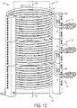
- the illustrative reaction chamber 14 includes a plurality of independent coils, illustratively three induction coils 95a, 95b, 95c, in a stacked arrangement along the longitudinal length of the reaction chamber 14.
- Coils 95a, 95b, 95c each include approximately ten windings that are concentrated around a particular region of the reaction chamber 14.
- first coils 95a are positioned around an upper region 14a of the reaction chamber 14 near the upper end
- second coils 95b are positioned around a middle region 14b of the reaction chamber 14
- third coils 95c are positioned around a lower region 14c of the reaction chamber 14 near the lower end 32.
- Each of the coils 95a, 95b, 95c is independently controlled in order to selectively vary the temperature in the respective upper, middle, and lower regions 14a, 14b, 14c of the reaction chamber 14.
- the first coil 95a, the second coil 95b, and third coil 95c are used to provide a temperature profile within the reaction chamber 14, in which the temperature increases in the direction of gas flow (i.e., in the downward direction). Therefore, the temperature in the lower region 14c of the reaction chamber 14 is greater than the temperature in the upper and middle regions 14a, 14b of the chamber 14. Since temperature is a key variable for the deposition reaction, more tantalum may deposit onto the substrates 100 in regions with increased temperature. As such, the elevated temperature in the lower region 14c of the illustrative reaction chamber 14 may compensate for the decreased concentration of tantalum in the lower region 14c and drive the deposition reaction.
- Induction coils 95a, 95b, 95c were used to create descending, ascending, and uniform temperature profiles within the reaction chamber 14.
- the descending profile varied the temperature of the reaction chamber 14 between approximately 1050° C near the upper end 30 and approximately 900° C near the lower end 32.
- the ascending temperature profile heated the upper end 30 of the reaction chamber 14 to approximately 900° C and the lower end 32 to approximately 1050° C.
- the uniform temperature profile maintained the temperature in each region 14a, 14b, 14c of the reaction chamber 14 at approximately 925° C.
- CVI cycles were conducted on multiple substrates 100 for approximately 10 hours.
- Thermocouples (not shown) were positioned within the reaction chamber 14, each corresponding to one of the induction coils 95a, 95b, 95c, in order to monitor the temperature profile during these tests.
- the ascending temperature profile affected the deposition efficiency but did not affect the weight variance in a statistically significant way.
- the ascending temperature profile increased the deposition efficiency, thereby decreasing the overall amount of time needed to form a porous tantalum implant.
- the descending temperature profile affected both the deposition efficiency and the weight variance. Specifically, the descending temperature profile decreased the deposition efficiency and increased the weight variance, thereby increasing the overall amount of time needed to form a porous tantalum implant.
- the CVI cycle occurs at a temperature of at least 900° C and, therefore, known CVI devices may take several hours to sufficiently cool the deposition chamber 28 in order to remove the substrates 100.
- the overall amount of time needed to produce porous tantalum implants may be reduced by decreasing the cooling period of a CVI cycle.
- the configuration and position of the heat source affects the cooling time.
- rapidly cooling, or quenching, the substrates 100 may adversely affect the chemical and mechanical properties of the implants.
- an illustrative embodiment of the reaction chamber 14 is configured to rapidly cool the deposition chamber 28 after completion of a CVI cycle.
- the reaction chamber 14 includes a supply of argon gas 98 that may be injected into the reaction chamber 14 following a CVI cycle.
- Argon boils at approximately -186° C (-303° F) and, therefore, is a cold gas at room temperature.
- argon gas 98 may be used to cool the reaction chamber 14.
- the flow rate of argon gas 98 may be as low as approximately 500, 1000, or 1500 sccm, and as high as approximately 8,000, 9,000, or 10,000 sccm, or within any range delimited by any pair of the foregoing values.
- the argon gas 98 may be held under a vacuum level as low as approximately 0, 2, or 4 Torr or as high as approximately 6, 8, or 10 Torr, or within any range delimited by any pair of the foregoing values. However, if a heat source is positioned around the reaction chamber 14 during the cooling period, the flush of argon gas 98 is potentially less effective.
- the illustrative embodiment of the reaction chamber 14 may further include a removable induction coil 99 positioned around a vacuum chamber 101 and the reaction chamber 14.
- the removable induction coil 99 may be removed from the reaction chamber 14 through pneumatic, hydraulic, or automatic means.
- the removable induction coil 99 is lifted from the reaction chamber 14 and is stored at a position above the reaction chamber 14.
- the vacuum chamber 101 is intermediate the induction coil 99 and the reaction chamber 14 and continues to surround the reaction chamber 14 after the induction coil 99 is removed in order to facilitate the flow of argon gas 98 and, therefore, the cooling process.
- the simultaneous removal of heat and the flush of argon gas 98, under vacuum provide maximum cooling potential.
- Cooling period time and the chemical and mechanical properties of the substrates 100 were the outputs used to quantify these tests.
- the level of vacuum and the flow rate of the argon gas 98 were statistically significant factors for rapid cooling. Shorter cooling periods were observed when the flow rate of argon gas 98 was increased and combined with a low level of vacuum. For example, the tests indicated that when the flow rate of argon gas 98 was 5,000 sccm, held under vacuum at a pressure of approximately 10 Torr, the cooling period was reduced from approximately 340 minutes to approximately 260 minutes. It also was observed that the rapid cooling process did not adversely affect the chemical and mechanical properties of the porous tantalum substrates 100. Following the rapid cooling period, the ultimate compressive strength, the specific compressive strength, the ductility, and the chemical properties of the substrates 100 were analyzed and determined to be acceptable.
- the above-described furnace configurations may be configured to self-clean.
- tantalum builds up on the inner surface 36 of the side wall 34 of the reaction chamber 14.
- the tantalum build-up is removed by manually disassembling the apparatus 10 and using acidic or caustic stripping agents such as hydrofluoric acid.
- the illustrative reaction chamber 14 may implement a chlorine stripping process, whereby the reaction chamber 14 is heated and chlorine gas is injected into the reaction chamber 14 to react with the solid tantalum build-up and convert the tantalum to tantalum chloride gas, which may be exhausted from the reaction chamber 14.
- the chlorine stripping gas may be injected directly into the deposition chamber 28 to clean the inner surface 36 of the side wall 34 via gas input 96 ( FIG. 11 ) or another suitable gas input.
- the chlorine stripping gas may first be injected into chlorination chamber 26 via chlorine gas input 16 ( FIG. 2 ) before reaching deposition chamber 28. If the chlorine stripping gas will travel through the chlorination chamber 26, any loose tantalum nuggets or scraps in the pot 50 may be removed manually (e.g., by dumping the pot 50) to avoid "wasting" the chlorine stripping gas reaction on these loose source materials.
- the temperature of the chlorination chamber 26 may be lower during the self-cleaning cycle (e.g., less than 500° C) than during the CVI production cycle (e.g., more than 500° C) to avoid "wasting" the chlorine stripping gas reaction on these loose source materials.
- the self-cleaning cycle may occur after a series of CVI production cycles. Any coated substrates 100 may be removed from the reaction chamber 14 before running the self-cleaning cycle to avoid "wasting" the chlorine stripping gas reaction by stripping tantalum from the coated substrates 100.
- a metal or graphite foil insert or film 36a may be secured to the inner surface 36 of the side wall 34 of the reaction chamber 14, onto which tantalum may deposit during a CVI cycle.
- the foil insert 36a may be easily removed and replaced as desired following one or more CVI cycles.
- the foil insert 36a is shown being peeled away from the inner surface 36 of the side wall 34.
- the foil insert 36a may have an adhesive backing that allows for selective application and removal.
Landscapes
- Chemical & Material Sciences (AREA)
- Engineering & Computer Science (AREA)
- General Chemical & Material Sciences (AREA)
- Chemical Kinetics & Catalysis (AREA)
- Materials Engineering (AREA)
- Mechanical Engineering (AREA)
- Metallurgy (AREA)
- Organic Chemistry (AREA)
- Health & Medical Sciences (AREA)
- Oral & Maxillofacial Surgery (AREA)
- Vascular Medicine (AREA)
- Cardiology (AREA)
- Manufacturing & Machinery (AREA)
- Transplantation (AREA)
- Biomedical Technology (AREA)
- Heart & Thoracic Surgery (AREA)
- Orthopedic Medicine & Surgery (AREA)
- Life Sciences & Earth Sciences (AREA)
- Animal Behavior & Ethology (AREA)
- General Health & Medical Sciences (AREA)
- Public Health (AREA)
- Veterinary Medicine (AREA)
- Chemical Vapour Deposition (AREA)
- Materials For Medical Uses (AREA)
Claims (15)
- Procédé de fonctionnement d'un appareil d'infiltration de vapeur chimique (10) pour produire un implant orthopédique, le procédé comprenant les étapes de :disposition d'un substrat poreux (100) dans une chambre de réaction (14) de l'appareil d'infiltration de vapeur chimique, la chambre de réaction (14) étant définie par une extrémité supérieure (30), une extrémité inférieure (32) et une paroi latérale cylindrique (34) s'étendant entre les extrémités supérieure et inférieure ;exposition du substrat poreux (100) à un premier gaz et à un second gaz dans la chambre de réaction (14), le premier gaz s'écoulant vers le haut dans la chambre et le second gaz s'écoulant vers le bas dans la chambre de réaction, lesdits premier et second gaz réagissant dans la chambre de réaction (14) pour déposer un métal biocompatible sur le substrat poreux (100) ; etmodification du niveau de vide dans la chambre de réaction (14) pendant l'étape d'exposition.
- Procédé selon la revendication 1, ladite étape de modification comprenant la manipulation d'une vanne d'un système de vide à partir d'une position ouverte pour soumettre la chambre de réaction à un niveau de vide maximal à partir du système de vide, et jusqu'à une position fermée pour séparer le système de vide de la chambre de réaction.
- Procédé selon la revendication 1, ladite étape de modification comprenant l'exposition répétée de la chambre de réaction à un système de vide et la séparation de la chambre de réaction du système de vide.
- Procédé selon la revendication 1, ladite étape de modification comprenant le fonctionnement de la chambre de réaction dans une pluralité de cycles de vide, chaque cycle de vide présentant un niveau de vide relativement élevé et un niveau de vide relativement faible.
- Procédé selon la revendication 1, comprenant en outre au moins une fermeture parmi :la fermeture d'une entrée de premier gaz dans la chambre de réaction pendant l'étape de modification pour empêcher l'écoulement de davantage du premier gaz dans la chambre de réaction ; etla fermeture d'une entrée de second gaz dans la chambre de réaction pendant l'étape de modification pour empêcher l'écoulement de davantage du second gaz dans la chambre de réaction.
- Procédé selon la revendication 1, pendant l'étape d'exposition, ladite extrémité supérieure de la chambre de réaction étant commandée à une première température par un système de commande de température et ladite extrémité inférieure de la chambre de réaction étant commandée à une seconde température par le système de commande de température, la seconde température dépassant la première température.
- Procédé selon la revendication 1, ledit métal biocompatible comprenant du tantale, ledit premier gaz comprenant du chlorure de tantale et ledit second gaz comprenant de l'hydrogène.
- Procédé selon la revendication 1, dans la chambre de réaction, ledit appareil comprenant une chambre de chloration chauffée 26 et une chambre de dépôt chauffée 28, ledit chlorure de tantale se formant dans la chambre de chloration et s'écoulant vers le haut dans la chambre de dépôt et le gaz hydrogène et l'air s'écoulant vers le bas dans la chambre de dépôt par une entrée de gaz hydrogène et une entrée d'air placées à proximité de l'extrémité supérieure de la chambre de réaction.
- Procédé selon la revendication 1, ladite étape de modification comprenant la soumission de la chambre de réaction à une pluralité de cycles de vide qui comprennent chacun la diminution de la pression dans la chambre de réaction et l'augmentation de la pression dans la chambre de réaction.
- Procédé selon la revendication 9, ladite pluralité de cycles de vide comprenant chacun la diminution de la pression dans la chambre de réaction et puis par la suite l'augmentation de la pression dans la chambre de réaction jusqu'à ce qu'une pression prédéfinie soit atteinte et ensuite le maintien de ladite pression prédéfinie pendant un laps de temps.
- Procédé selon la revendication 1, comprenant en outre le balayage de la chambre de réaction avec du gaz argon.
- Appareil d'infiltration de vapeur chimique (10) pour produire un implant orthopédique, l'appareil comprenant :une chambre de réaction (14) comportant une entrée de premier gaz destinée à recevoir un premier gaz et une entrée de second gaz destinée à recevoir un second gaz, la chambre de réaction (14) étant définie par une extrémité supérieure (30), une extrémité inférieure (32) et une paroi latérale cylindrique (34) s'étendant entre les extrémités supérieure et inférieure, un premier gaz et un second gaz, ledit premier gaz s'écoulant vers le haut dans la chambre (14) et ledit second gaz s'écoulant vers le bas dans la chambre de réaction (14), les premier et second gaz réagissant pour former un métal biocompatible ;une unité de rangement (42) dans la chambre de réaction (14) qui est dimensionnée pour contenir une pluralité de substrats poreux (100) dans un agencement empilé, le métal biocompatible se déposant sur la pluralité de substrats poreux (100) ; etun actionneur conçu pour faire pivoter l'unité de rangement et la pluralité de substrats poreux sur l'unité de rangement par rapport à la chambre de réaction.
- Appareil selon la revendication 12, comprenant en outre un système de commande de température, l'extrémité supérieure (30) étant commandée à une première température par le système de commande de température et l'extrémité inférieure (32) étant commandée à une seconde température par le système de commande de température, la seconde température dépassant la première température.
- Appareil selon la revendication 13, ladite chambre de réaction (14) comprenant une sortie de gaz à proximité de l'extrémité inférieure (32) de sorte que le second gaz s'écoule à travers la chambre de réaction (14) de l'extrémité supérieure (30) à l'extrémité inférieure (32).
- Appareil selon la revendication 12, comprenant en outre une cuve (50) qui contient une source du métal biocompatible, la cuve se trouvant en dessous de l'unité de rangement (42).
Applications Claiming Priority (2)
| Application Number | Priority Date | Filing Date | Title |
|---|---|---|---|
| US201161497803P | 2011-06-16 | 2011-06-16 | |
| PCT/US2012/042402 WO2012174207A2 (fr) | 2011-06-16 | 2012-06-14 | Appareil et procédé d'infiltration de vapeur chimique |
Publications (2)
| Publication Number | Publication Date |
|---|---|
| EP2721191A2 EP2721191A2 (fr) | 2014-04-23 |
| EP2721191B1 true EP2721191B1 (fr) | 2022-09-14 |
Family
ID=46319203
Family Applications (1)
| Application Number | Title | Priority Date | Filing Date |
|---|---|---|---|
| EP12728162.4A Active EP2721191B1 (fr) | 2011-06-16 | 2012-06-14 | Appareil et procédé d'infiltration de vapeur chimique |
Country Status (5)
| Country | Link |
|---|---|
| US (2) | US8956683B2 (fr) |
| EP (1) | EP2721191B1 (fr) |
| AU (1) | AU2012271612B2 (fr) |
| CA (1) | CA2839406C (fr) |
| WO (1) | WO2012174207A2 (fr) |
Families Citing this family (15)
| Publication number | Priority date | Publication date | Assignee | Title |
|---|---|---|---|---|
| AU2012271612B2 (en) | 2011-06-16 | 2017-08-31 | Zimmer, Inc. | Chemical vapor infiltration apparatus and process |
| JP6306411B2 (ja) * | 2014-04-17 | 2018-04-04 | 株式会社日立国際電気 | 半導体装置の製造方法、基板処理装置およびプログラム |
| US10131985B2 (en) * | 2016-03-21 | 2018-11-20 | Goodrich Corporation | System and method for enhancing a diffusion limited CVI/CVD process |
| US10364491B2 (en) * | 2016-11-02 | 2019-07-30 | Georgia Tech Research Corporation | Process to chemically modify polymeric materials by static, low-pressure infiltration of reactive gaseous molecules |
| US10486967B2 (en) * | 2017-05-04 | 2019-11-26 | Honeywell International Inc. | Inductively heated methane pyrolysis reactor for advanced oxygen recovery in environmental control and life support systems |
| US11419725B2 (en) | 2017-11-22 | 2022-08-23 | Zimmer, Inc. | Implants including a monolithic layer of biocompatible metallic material |
| US10731252B2 (en) | 2018-05-25 | 2020-08-04 | Rolls-Royce High Temperature Composites | Apparatus and method for coating specimens |
| US11691924B2 (en) | 2020-02-21 | 2023-07-04 | Raytheon Technologies Corporation | CVI matrix densification process |
| US12515169B2 (en) | 2020-06-26 | 2026-01-06 | Zimmer, Inc. | Vacuum generation process for deposition of biomedical implant materials |
| CN112813404A (zh) * | 2020-12-30 | 2021-05-18 | 宁夏东方钽业股份有限公司 | 一种钽镀层及其制备方法及牙种植体 |
| CN113846307A (zh) * | 2021-07-30 | 2021-12-28 | 陕西宏大空天新材料研究院有限责任公司 | 一种在钴铬钼合金骨架上沉积钽金属涂层的制备方法 |
| US12000046B1 (en) * | 2021-12-29 | 2024-06-04 | Rolls-Royce High Temperature Composites, Inc. | Load assemblies for loading parts in a furnace |
| US11932941B1 (en) | 2021-12-29 | 2024-03-19 | Rolls-Royce High Temperature Composites, Inc. | Load assemblies for loading parts in a furnace |
| US12078417B1 (en) | 2021-12-29 | 2024-09-03 | Rolls-Royce High Temperature Composites, Inc. | Load assemblies for loading parts in a furnace |
| AU2023200191B2 (en) | 2022-01-27 | 2024-01-18 | Zimmer, Inc. | Chemical vapor infiltration apparatus and assembly for gas inflow in reaction chamber |
Citations (2)
| Publication number | Priority date | Publication date | Assignee | Title |
|---|---|---|---|---|
| US4990374A (en) * | 1989-11-28 | 1991-02-05 | Cvd Incorporated | Selective area chemical vapor deposition |
| US20090139448A1 (en) * | 2007-11-29 | 2009-06-04 | Hironobu Hirata | Vapor phase growth apparatus ans vapor phase growth method |
Family Cites Families (62)
| Publication number | Priority date | Publication date | Assignee | Title |
|---|---|---|---|---|
| US6482262B1 (en) | 1959-10-10 | 2002-11-19 | Asm Microchemistry Oy | Deposition of transition metal carbides |
| US4138512A (en) | 1977-10-17 | 1979-02-06 | The United States Of America As Represented By The Secretary Of The Army | Process for chemical vapor deposition of a homogeneous alloy of refractory metals |
| USRE30626E (en) | 1979-09-14 | 1981-05-26 | Ultramet of Pacoima | Spheres obtained by vapor deposition for use in ball point pens |
| US4699082A (en) | 1983-02-25 | 1987-10-13 | Liburdi Engineering Limited | Apparatus for chemical vapor deposition |
| US4996942A (en) | 1987-03-31 | 1991-03-05 | Epsilon Technology, Inc. | Rotatable substrate supporting susceptor with temperature sensors |
| US4821674A (en) | 1987-03-31 | 1989-04-18 | Deboer Wiebe B | Rotatable substrate supporting mechanism with temperature sensing device for use in chemical vapor deposition equipment |
| US5198034A (en) | 1987-03-31 | 1993-03-30 | Epsilon Technology, Inc. | Rotatable substrate supporting mechanism with temperature sensing device for use in chemical vapor deposition equipment |
| US5169685A (en) | 1989-06-12 | 1992-12-08 | General Electric Company | Method for forming non-columnar deposits by chemical vapor deposition |
| SE9001009L (sv) | 1990-03-21 | 1991-09-22 | Ytbolaget I Uppsala Ab | Foerfarande foer att bilda ett haart och slitagebestaendigt skikt med god vidhaeftning paa titan eller titanregleringar och produkter, framstaellda enligt foerfarandet |
| US5102694A (en) | 1990-09-27 | 1992-04-07 | Cvd Incorporated | Pulsed chemical vapor deposition of gradient index optical material |
| US5283109A (en) | 1991-04-15 | 1994-02-01 | Ultramet | High temperature resistant structure |
| US5154970A (en) | 1991-07-16 | 1992-10-13 | Ultramet | High temperature resistant reticulated foam structure and process |
| US5282861A (en) * | 1992-03-11 | 1994-02-01 | Ultramet | Open cell tantalum structures for cancellous bone implants and cell and tissue receptors |
| US5306666A (en) | 1992-07-24 | 1994-04-26 | Nippon Steel Corporation | Process for forming a thin metal film by chemical vapor deposition |
| US5443647A (en) | 1993-04-28 | 1995-08-22 | The United States Of America As Represented By The Secretary Of The Army | Method and apparatus for depositing a refractory thin film by chemical vapor deposition |
| JPH0799162A (ja) | 1993-06-21 | 1995-04-11 | Hitachi Ltd | Cvdリアクタ装置 |
| US5348774A (en) * | 1993-08-11 | 1994-09-20 | Alliedsignal Inc. | Method of rapidly densifying a porous structure |
| US5443515A (en) | 1994-01-26 | 1995-08-22 | Implex Corporation | Vertebral body prosthetic implant with slidably positionable stabilizing member |
| US5780157A (en) | 1994-06-06 | 1998-07-14 | Ultramet | Composite structure |
| JPH0864559A (ja) * | 1994-06-14 | 1996-03-08 | Fsi Internatl Inc | 基板面から不要な物質を除去する方法 |
| JP3744554B2 (ja) | 1994-09-09 | 2006-02-15 | キヤノンアネルバ株式会社 | 薄膜形成方法 |
| DE69505694T2 (de) * | 1994-11-16 | 1999-05-20 | The B.F. Goodrich Co., Akron, Ohio | Vorrichtung zur druckfeld cvd/cvi, verfahren und produkt |
| US5577263A (en) | 1995-03-22 | 1996-11-19 | Alliedsignal Inc. | Chemical vapor deposition of fine grained rhenium on carbon based substrates |
| WO1996039974A1 (fr) | 1995-06-07 | 1996-12-19 | Implex Corporation | Prothese de remplissage de canal central de tete de femur |
| US6083560A (en) * | 1995-11-16 | 2000-07-04 | Alliant Techsystems Inc | Process for controlled deposition profile forced flow chemical vapor infiltration |
| US5876793A (en) | 1996-02-21 | 1999-03-02 | Ultramet | Fine powders and method for manufacturing |
| US5874131A (en) | 1996-10-02 | 1999-02-23 | Micron Technology, Inc. | CVD method for forming metal-containing films |
| US5849092A (en) * | 1997-02-25 | 1998-12-15 | Applied Materials, Inc. | Process for chlorine trifluoride chamber cleaning |
| US5919531A (en) | 1997-03-26 | 1999-07-06 | Gelest, Inc. | Tantalum and tantalum-based films and methods of making the same |
| US6352594B2 (en) | 1997-08-11 | 2002-03-05 | Torrex | Method and apparatus for improved chemical vapor deposition processes using tunable temperature controlled gas injectors |
| AU4071599A (en) | 1998-05-07 | 1999-11-23 | Advanced Bio Surfaces, Inc. | Porous composite biomaterial and biopolymer system |
| US6063442A (en) | 1998-10-26 | 2000-05-16 | Implex Corporation | Bonding of porous materials to other materials utilizing chemical vapor deposition |
| GB9901041D0 (en) * | 1999-01-18 | 1999-03-10 | Dunlop Aerospace Ltd | Densification of porous bodies |
| US6641918B1 (en) | 1999-06-03 | 2003-11-04 | Powdermet, Inc. | Method of producing fine coated tungsten carbide particles |
| US20010051215A1 (en) | 2000-04-13 | 2001-12-13 | Gelest, Inc. | Methods for chemical vapor deposition of titanium-silicon-nitrogen films |
| US6756088B2 (en) | 2000-08-29 | 2004-06-29 | Micron Technology, Inc. | Methods of forming coatings on gas-dispersion fixtures in chemical-vapor-deposition systems |
| DE10056029A1 (de) | 2000-11-11 | 2002-05-16 | Aixtron Ag | Verfahren und Vorrichtung zur Temperatursteuerung der Oberflächentemperaturen von Substraten in einem CVD-Reaktor |
| WO2002070142A1 (fr) | 2000-12-06 | 2002-09-12 | Angstron Systems, Inc. | Procédé et appareil améliorant la régulation thermique pour le dépôt de couche atomique |
| US6770146B2 (en) | 2001-02-02 | 2004-08-03 | Mattson Technology, Inc. | Method and system for rotating a semiconductor wafer in processing chambers |
| US20020162500A1 (en) | 2001-05-02 | 2002-11-07 | Applied Materials, Inc. | Deposition of tungsten silicide films |
| US7211144B2 (en) | 2001-07-13 | 2007-05-01 | Applied Materials, Inc. | Pulsed nucleation deposition of tungsten layers |
| EP1424724A4 (fr) | 2001-08-14 | 2007-10-24 | Powdec Kk | Appareil d'epitaxie a phase vapeur chimique |
| TW589684B (en) | 2001-10-10 | 2004-06-01 | Applied Materials Inc | Method for depositing refractory metal layers employing sequential deposition techniques |
| US7063981B2 (en) | 2002-01-30 | 2006-06-20 | Asm International N.V. | Active pulse monitoring in a chemical reactor |
| US6833161B2 (en) | 2002-02-26 | 2004-12-21 | Applied Materials, Inc. | Cyclical deposition of tungsten nitride for metal oxide gate electrode |
| US6932871B2 (en) | 2002-04-16 | 2005-08-23 | Applied Materials, Inc. | Multi-station deposition apparatus and method |
| US7479301B2 (en) | 2002-05-01 | 2009-01-20 | Danfoss A/S | Method for modifying a metallic surface |
| FR2854168B1 (fr) * | 2003-04-28 | 2007-02-09 | Messier Bugatti | Commande ou modelisation de procede d'infiltration chimique en phase vapeur pour la densification de substrats poreux par du carbone |
| CN1997770A (zh) | 2004-07-30 | 2007-07-11 | Lpe公司 | 具有控制定位的衬托器的外延反应器 |
| DE102004056170A1 (de) | 2004-08-06 | 2006-03-16 | Aixtron Ag | Vorrichtung und Verfahren zur chemischen Gasphasenabscheidung mit hohem Durchsatz |
| KR100636036B1 (ko) | 2004-11-19 | 2006-10-18 | 삼성전자주식회사 | 티타늄 질화막 형성 방법 및 이를 수행하기 위한 장치 |
| EP1888810A2 (fr) | 2004-12-10 | 2008-02-20 | Koninklijke Philips Electronics N.V. | Reglage de la temperature du substrat pour le depot chimique en phase vapeur par combustion |
| US20070061006A1 (en) * | 2005-09-14 | 2007-03-15 | Nathan Desatnik | Methods of making shape memory films by chemical vapor deposition and shape memory devices made thereby |
| NZ550531A (en) * | 2006-10-12 | 2009-05-31 | Canterprise Ltd | A method of producing an implant with an improved bone growth surface |
| MX2009004149A (es) * | 2006-10-19 | 2009-08-07 | Univ Arkansas | Metodos y aparatos para hacer recubrimientos utilizando rocio electrostatico. |
| EP2094406B1 (fr) | 2006-11-22 | 2015-10-14 | Soitec | Procédé, appareil et clapet obturateur pour la production d'un matériau semiconducteur monocristallin du type iii-v |
| US7959973B2 (en) | 2006-11-29 | 2011-06-14 | Honeywell International Inc. | Pressure swing CVI/CVD |
| EP1927325A1 (fr) | 2006-12-01 | 2008-06-04 | ZL Microdent-Attachment GmbH & Co. KG | Implant et procédé destinés à la modification de la surface d'un implant |
| KR100830590B1 (ko) | 2007-06-01 | 2008-05-21 | 삼성전자주식회사 | 텅스텐막, 그 형성 방법, 이를 포함한 반도체 소자 및 그반도체 소자의 형성 방법 |
| US7988787B2 (en) * | 2007-08-27 | 2011-08-02 | Caterpillar Inc. | Workpiece support system and method |
| KR100998011B1 (ko) | 2008-05-22 | 2010-12-03 | 삼성엘이디 주식회사 | 화학기상 증착장치 |
| AU2012271612B2 (en) | 2011-06-16 | 2017-08-31 | Zimmer, Inc. | Chemical vapor infiltration apparatus and process |
-
2012
- 2012-06-14 AU AU2012271612A patent/AU2012271612B2/en active Active
- 2012-06-14 US US13/523,073 patent/US8956683B2/en active Active
- 2012-06-14 EP EP12728162.4A patent/EP2721191B1/fr active Active
- 2012-06-14 CA CA2839406A patent/CA2839406C/fr active Active
- 2012-06-14 WO PCT/US2012/042402 patent/WO2012174207A2/fr not_active Ceased
-
2015
- 2015-02-12 US US14/620,287 patent/US9277998B2/en active Active
Patent Citations (2)
| Publication number | Priority date | Publication date | Assignee | Title |
|---|---|---|---|---|
| US4990374A (en) * | 1989-11-28 | 1991-02-05 | Cvd Incorporated | Selective area chemical vapor deposition |
| US20090139448A1 (en) * | 2007-11-29 | 2009-06-04 | Hironobu Hirata | Vapor phase growth apparatus ans vapor phase growth method |
Also Published As
| Publication number | Publication date |
|---|---|
| US9277998B2 (en) | 2016-03-08 |
| US20120321779A1 (en) | 2012-12-20 |
| WO2012174207A3 (fr) | 2013-05-10 |
| CA2839406C (fr) | 2019-10-29 |
| CA2839406A1 (fr) | 2012-12-20 |
| EP2721191A2 (fr) | 2014-04-23 |
| US20150150682A1 (en) | 2015-06-04 |
| US8956683B2 (en) | 2015-02-17 |
| AU2012271612B2 (en) | 2017-08-31 |
| WO2012174207A2 (fr) | 2012-12-20 |
| AU2012271612A1 (en) | 2014-02-06 |
Similar Documents
| Publication | Publication Date | Title |
|---|---|---|
| EP2721191B1 (fr) | Appareil et procédé d'infiltration de vapeur chimique | |
| US20070264807A1 (en) | Cleaining Process and Operating Process for a Cvd Reactor | |
| CA2880824C (fr) | Revetement de tantale a couche mince pour implants medicaux | |
| JP5666899B2 (ja) | 炭化タンタル被覆炭素材料の製造方法 | |
| JP5612574B2 (ja) | ワークピース上に反応ガス混合物から層を析出するためのcvd反応器 | |
| JP2013503464A (ja) | Cvd方法およびcvd反応炉 | |
| Rie et al. | Investigation of PA-CVD of TiN: relations between process parameters, spectroscopic measurements and layer properties | |
| KR20190039323A (ko) | 탄소 층을 도포하기 위한 장치 및 방법 | |
| EP1501962B1 (fr) | Procede de modification d'une surface metallique | |
| TW202227381A (zh) | 用於嵌入陶瓷件的加熱器之塗層導體 | |
| WO2018021466A1 (fr) | Film de nitrure de vanadium, élément revêtu d'un film de nitrure de vanadium et procédé de fabrication associé | |
| TWI496938B (zh) | A heat treatment method including a heating step, a processing step and a cooling step | |
| RU2225354C2 (ru) | Способ получения композиционного материала | |
| JP2020037491A (ja) | 酸素欠損型金属酸化物の製造方法 | |
| EP3248714A1 (fr) | Système de traitement de poudre et procédé de traitement thermique de poudre | |
| Sveen et al. | Effect of filament temperature and deposition time on the formation of tungsten silicide with silane | |
| Krumdieck | Conformality of ceramic oxygen barrier coatings on micro-and nanoscale features by Pulsed-Pressure MOCVD | |
| CROITORU et al. | Materials and Technologies Used in Present Dental Implants Manufacturing | |
| JP2010031304A (ja) | 熱処理装置 | |
| JP2019031415A (ja) | シリコン単結晶の製造方法 | |
| JPH0661963U (ja) | パルスcvi装置の基材保持具 |
Legal Events
| Date | Code | Title | Description |
|---|---|---|---|
| PUAI | Public reference made under article 153(3) epc to a published international application that has entered the european phase |
Free format text: ORIGINAL CODE: 0009012 |
|
| 17P | Request for examination filed |
Effective date: 20140116 |
|
| AK | Designated contracting states |
Kind code of ref document: A2 Designated state(s): AL AT BE BG CH CY CZ DE DK EE ES FI FR GB GR HR HU IE IS IT LI LT LU LV MC MK MT NL NO PL PT RO RS SE SI SK SM TR |
|
| DAX | Request for extension of the european patent (deleted) | ||
| STAA | Information on the status of an ep patent application or granted ep patent |
Free format text: STATUS: EXAMINATION IS IN PROGRESS |
|
| 17Q | First examination report despatched |
Effective date: 20161102 |
|
| GRAP | Despatch of communication of intention to grant a patent |
Free format text: ORIGINAL CODE: EPIDOSNIGR1 |
|
| STAA | Information on the status of an ep patent application or granted ep patent |
Free format text: STATUS: GRANT OF PATENT IS INTENDED |
|
| INTG | Intention to grant announced |
Effective date: 20220324 |
|
| GRAS | Grant fee paid |
Free format text: ORIGINAL CODE: EPIDOSNIGR3 |
|
| GRAA | (expected) grant |
Free format text: ORIGINAL CODE: 0009210 |
|
| STAA | Information on the status of an ep patent application or granted ep patent |
Free format text: STATUS: THE PATENT HAS BEEN GRANTED |
|
| AK | Designated contracting states |
Kind code of ref document: B1 Designated state(s): AL AT BE BG CH CY CZ DE DK EE ES FI FR GB GR HR HU IE IS IT LI LT LU LV MC MK MT NL NO PL PT RO RS SE SI SK SM TR |
|
| REG | Reference to a national code |
Ref country code: GB Ref legal event code: FG4D |
|
| REG | Reference to a national code |
Ref country code: CH Ref legal event code: EP |
|
| REG | Reference to a national code |
Ref country code: DE Ref legal event code: R096 Ref document number: 602012078746 Country of ref document: DE |
|
| REG | Reference to a national code |
Ref country code: IE Ref legal event code: FG4D |
|
| REG | Reference to a national code |
Ref country code: AT Ref legal event code: REF Ref document number: 1518736 Country of ref document: AT Kind code of ref document: T Effective date: 20221015 |
|
| REG | Reference to a national code |
Ref country code: LT Ref legal event code: MG9D |
|
| REG | Reference to a national code |
Ref country code: NL Ref legal event code: MP Effective date: 20220914 |
|
| PG25 | Lapsed in a contracting state [announced via postgrant information from national office to epo] |
Ref country code: SE Free format text: LAPSE BECAUSE OF FAILURE TO SUBMIT A TRANSLATION OF THE DESCRIPTION OR TO PAY THE FEE WITHIN THE PRESCRIBED TIME-LIMIT Effective date: 20220914 Ref country code: RS Free format text: LAPSE BECAUSE OF FAILURE TO SUBMIT A TRANSLATION OF THE DESCRIPTION OR TO PAY THE FEE WITHIN THE PRESCRIBED TIME-LIMIT Effective date: 20220914 Ref country code: NO Free format text: LAPSE BECAUSE OF FAILURE TO SUBMIT A TRANSLATION OF THE DESCRIPTION OR TO PAY THE FEE WITHIN THE PRESCRIBED TIME-LIMIT Effective date: 20221214 Ref country code: LV Free format text: LAPSE BECAUSE OF FAILURE TO SUBMIT A TRANSLATION OF THE DESCRIPTION OR TO PAY THE FEE WITHIN THE PRESCRIBED TIME-LIMIT Effective date: 20220914 Ref country code: LT Free format text: LAPSE BECAUSE OF FAILURE TO SUBMIT A TRANSLATION OF THE DESCRIPTION OR TO PAY THE FEE WITHIN THE PRESCRIBED TIME-LIMIT Effective date: 20220914 Ref country code: FI Free format text: LAPSE BECAUSE OF FAILURE TO SUBMIT A TRANSLATION OF THE DESCRIPTION OR TO PAY THE FEE WITHIN THE PRESCRIBED TIME-LIMIT Effective date: 20220914 |
|
| REG | Reference to a national code |
Ref country code: AT Ref legal event code: MK05 Ref document number: 1518736 Country of ref document: AT Kind code of ref document: T Effective date: 20220914 |
|
| PG25 | Lapsed in a contracting state [announced via postgrant information from national office to epo] |
Ref country code: HR Free format text: LAPSE BECAUSE OF FAILURE TO SUBMIT A TRANSLATION OF THE DESCRIPTION OR TO PAY THE FEE WITHIN THE PRESCRIBED TIME-LIMIT Effective date: 20220914 Ref country code: GR Free format text: LAPSE BECAUSE OF FAILURE TO SUBMIT A TRANSLATION OF THE DESCRIPTION OR TO PAY THE FEE WITHIN THE PRESCRIBED TIME-LIMIT Effective date: 20221215 |
|
| PG25 | Lapsed in a contracting state [announced via postgrant information from national office to epo] |
Ref country code: SM Free format text: LAPSE BECAUSE OF FAILURE TO SUBMIT A TRANSLATION OF THE DESCRIPTION OR TO PAY THE FEE WITHIN THE PRESCRIBED TIME-LIMIT Effective date: 20220914 Ref country code: RO Free format text: LAPSE BECAUSE OF FAILURE TO SUBMIT A TRANSLATION OF THE DESCRIPTION OR TO PAY THE FEE WITHIN THE PRESCRIBED TIME-LIMIT Effective date: 20220914 Ref country code: PT Free format text: LAPSE BECAUSE OF FAILURE TO SUBMIT A TRANSLATION OF THE DESCRIPTION OR TO PAY THE FEE WITHIN THE PRESCRIBED TIME-LIMIT Effective date: 20230116 Ref country code: ES Free format text: LAPSE BECAUSE OF FAILURE TO SUBMIT A TRANSLATION OF THE DESCRIPTION OR TO PAY THE FEE WITHIN THE PRESCRIBED TIME-LIMIT Effective date: 20220914 Ref country code: CZ Free format text: LAPSE BECAUSE OF FAILURE TO SUBMIT A TRANSLATION OF THE DESCRIPTION OR TO PAY THE FEE WITHIN THE PRESCRIBED TIME-LIMIT Effective date: 20220914 Ref country code: AT Free format text: LAPSE BECAUSE OF FAILURE TO SUBMIT A TRANSLATION OF THE DESCRIPTION OR TO PAY THE FEE WITHIN THE PRESCRIBED TIME-LIMIT Effective date: 20220914 |
|
| PG25 | Lapsed in a contracting state [announced via postgrant information from national office to epo] |
Ref country code: SK Free format text: LAPSE BECAUSE OF FAILURE TO SUBMIT A TRANSLATION OF THE DESCRIPTION OR TO PAY THE FEE WITHIN THE PRESCRIBED TIME-LIMIT Effective date: 20220914 Ref country code: PL Free format text: LAPSE BECAUSE OF FAILURE TO SUBMIT A TRANSLATION OF THE DESCRIPTION OR TO PAY THE FEE WITHIN THE PRESCRIBED TIME-LIMIT Effective date: 20220914 Ref country code: IS Free format text: LAPSE BECAUSE OF FAILURE TO SUBMIT A TRANSLATION OF THE DESCRIPTION OR TO PAY THE FEE WITHIN THE PRESCRIBED TIME-LIMIT Effective date: 20230114 Ref country code: EE Free format text: LAPSE BECAUSE OF FAILURE TO SUBMIT A TRANSLATION OF THE DESCRIPTION OR TO PAY THE FEE WITHIN THE PRESCRIBED TIME-LIMIT Effective date: 20220914 |
|
| REG | Reference to a national code |
Ref country code: DE Ref legal event code: R097 Ref document number: 602012078746 Country of ref document: DE |
|
| PG25 | Lapsed in a contracting state [announced via postgrant information from national office to epo] |
Ref country code: NL Free format text: LAPSE BECAUSE OF FAILURE TO SUBMIT A TRANSLATION OF THE DESCRIPTION OR TO PAY THE FEE WITHIN THE PRESCRIBED TIME-LIMIT Effective date: 20220914 Ref country code: AL Free format text: LAPSE BECAUSE OF FAILURE TO SUBMIT A TRANSLATION OF THE DESCRIPTION OR TO PAY THE FEE WITHIN THE PRESCRIBED TIME-LIMIT Effective date: 20220914 |
|
| P01 | Opt-out of the competence of the unified patent court (upc) registered |
Effective date: 20230525 |
|
| PLBE | No opposition filed within time limit |
Free format text: ORIGINAL CODE: 0009261 |
|
| STAA | Information on the status of an ep patent application or granted ep patent |
Free format text: STATUS: NO OPPOSITION FILED WITHIN TIME LIMIT |
|
| PG25 | Lapsed in a contracting state [announced via postgrant information from national office to epo] |
Ref country code: DK Free format text: LAPSE BECAUSE OF FAILURE TO SUBMIT A TRANSLATION OF THE DESCRIPTION OR TO PAY THE FEE WITHIN THE PRESCRIBED TIME-LIMIT Effective date: 20220914 |
|
| 26N | No opposition filed |
Effective date: 20230615 |
|
| PG25 | Lapsed in a contracting state [announced via postgrant information from national office to epo] |
Ref country code: SI Free format text: LAPSE BECAUSE OF FAILURE TO SUBMIT A TRANSLATION OF THE DESCRIPTION OR TO PAY THE FEE WITHIN THE PRESCRIBED TIME-LIMIT Effective date: 20220914 |
|
| PG25 | Lapsed in a contracting state [announced via postgrant information from national office to epo] |
Ref country code: MC Free format text: LAPSE BECAUSE OF FAILURE TO SUBMIT A TRANSLATION OF THE DESCRIPTION OR TO PAY THE FEE WITHIN THE PRESCRIBED TIME-LIMIT Effective date: 20220914 |
|
| PG25 | Lapsed in a contracting state [announced via postgrant information from national office to epo] |
Ref country code: MC Free format text: LAPSE BECAUSE OF FAILURE TO SUBMIT A TRANSLATION OF THE DESCRIPTION OR TO PAY THE FEE WITHIN THE PRESCRIBED TIME-LIMIT Effective date: 20220914 |
|
| REG | Reference to a national code |
Ref country code: CH Ref legal event code: PL |
|
| REG | Reference to a national code |
Ref country code: BE Ref legal event code: MM Effective date: 20230630 |
|
| PG25 | Lapsed in a contracting state [announced via postgrant information from national office to epo] |
Ref country code: LU Free format text: LAPSE BECAUSE OF NON-PAYMENT OF DUE FEES Effective date: 20230614 |
|
| REG | Reference to a national code |
Ref country code: IE Ref legal event code: MM4A |
|
| PG25 | Lapsed in a contracting state [announced via postgrant information from national office to epo] |
Ref country code: LU Free format text: LAPSE BECAUSE OF NON-PAYMENT OF DUE FEES Effective date: 20230614 |
|
| PG25 | Lapsed in a contracting state [announced via postgrant information from national office to epo] |
Ref country code: IE Free format text: LAPSE BECAUSE OF NON-PAYMENT OF DUE FEES Effective date: 20230614 |
|
| PG25 | Lapsed in a contracting state [announced via postgrant information from national office to epo] |
Ref country code: IE Free format text: LAPSE BECAUSE OF NON-PAYMENT OF DUE FEES Effective date: 20230614 Ref country code: CH Free format text: LAPSE BECAUSE OF NON-PAYMENT OF DUE FEES Effective date: 20230630 |
|
| PG25 | Lapsed in a contracting state [announced via postgrant information from national office to epo] |
Ref country code: IT Free format text: LAPSE BECAUSE OF FAILURE TO SUBMIT A TRANSLATION OF THE DESCRIPTION OR TO PAY THE FEE WITHIN THE PRESCRIBED TIME-LIMIT Effective date: 20220914 Ref country code: BE Free format text: LAPSE BECAUSE OF NON-PAYMENT OF DUE FEES Effective date: 20230630 |
|
| PG25 | Lapsed in a contracting state [announced via postgrant information from national office to epo] |
Ref country code: BG Free format text: LAPSE BECAUSE OF FAILURE TO SUBMIT A TRANSLATION OF THE DESCRIPTION OR TO PAY THE FEE WITHIN THE PRESCRIBED TIME-LIMIT Effective date: 20220914 |
|
| PG25 | Lapsed in a contracting state [announced via postgrant information from national office to epo] |
Ref country code: BG Free format text: LAPSE BECAUSE OF FAILURE TO SUBMIT A TRANSLATION OF THE DESCRIPTION OR TO PAY THE FEE WITHIN THE PRESCRIBED TIME-LIMIT Effective date: 20220914 |
|
| PGFP | Annual fee paid to national office [announced via postgrant information from national office to epo] |
Ref country code: DE Payment date: 20250512 Year of fee payment: 14 |
|
| PGFP | Annual fee paid to national office [announced via postgrant information from national office to epo] |
Ref country code: GB Payment date: 20250513 Year of fee payment: 14 |
|
| PGFP | Annual fee paid to national office [announced via postgrant information from national office to epo] |
Ref country code: FR Payment date: 20250509 Year of fee payment: 14 |
|
| PG25 | Lapsed in a contracting state [announced via postgrant information from national office to epo] |
Ref country code: CY Free format text: LAPSE BECAUSE OF FAILURE TO SUBMIT A TRANSLATION OF THE DESCRIPTION OR TO PAY THE FEE WITHIN THE PRESCRIBED TIME-LIMIT; INVALID AB INITIO Effective date: 20120614 |
|
| PG25 | Lapsed in a contracting state [announced via postgrant information from national office to epo] |
Ref country code: HU Free format text: LAPSE BECAUSE OF FAILURE TO SUBMIT A TRANSLATION OF THE DESCRIPTION OR TO PAY THE FEE WITHIN THE PRESCRIBED TIME-LIMIT; INVALID AB INITIO Effective date: 20120614 |
|
| PG25 | Lapsed in a contracting state [announced via postgrant information from national office to epo] |
Ref country code: TR Free format text: LAPSE BECAUSE OF FAILURE TO SUBMIT A TRANSLATION OF THE DESCRIPTION OR TO PAY THE FEE WITHIN THE PRESCRIBED TIME-LIMIT Effective date: 20220914 |