EP2725141A2 - Mit Gelenken ausgestattetes Glied, das mit einem Wandbehandlungswerkzeug ausgestattet ist, und Fahrzeug zur Wandbehandlung eines Bauwerks - Google Patents
Mit Gelenken ausgestattetes Glied, das mit einem Wandbehandlungswerkzeug ausgestattet ist, und Fahrzeug zur Wandbehandlung eines Bauwerks Download PDFInfo
- Publication number
- EP2725141A2 EP2725141A2 EP13306474.1A EP13306474A EP2725141A2 EP 2725141 A2 EP2725141 A2 EP 2725141A2 EP 13306474 A EP13306474 A EP 13306474A EP 2725141 A2 EP2725141 A2 EP 2725141A2
- Authority
- EP
- European Patent Office
- Prior art keywords
- articulated
- arm
- vehicle
- limb
- pantograph
- Prior art date
- Legal status (The legal status is an assumption and is not a legal conclusion. Google has not performed a legal analysis and makes no representation as to the accuracy of the status listed.)
- Granted
Links
Images




Classifications
-
- E—FIXED CONSTRUCTIONS
- E01—CONSTRUCTION OF ROADS, RAILWAYS, OR BRIDGES
- E01H—STREET CLEANING; CLEANING OF PERMANENT WAYS; CLEANING BEACHES; DISPERSING OR PREVENTING FOG IN GENERAL CLEANING STREET OR RAILWAY FURNITURE OR TUNNEL WALLS
- E01H1/00—Removing undesirable matter from roads or like surfaces, with or without moistening of the surface
- E01H1/005—Mobile installations, particularly for upkeeping in situ road or railway furniture, for instance road barricades, traffic signs; Mobile installations particularly for upkeeping tunnel walls
Definitions
- the present invention relates to an articulated member comprising a wall treatment tool of a structure, in particular a tunnel wall washing device, and a vehicle for treating walls of a structure comprising one or, preferably, many of these articulated members. It has applications in the field of maintenance of road works or other and the manufacture of machinery for this maintenance.
- Wall cleaning machines are known.
- articulated arms carrying at their ends washing means are implemented.
- These arms are of the sliding / telescopic type for a linear displacement and / or pivot type type between their ends for flexion / extension. This results in a large footprint, especially when the arms are returned to their rest position / storage. This congestion has the effect of reducing the carrying capacity of the machines because a significant volume must be occupied by the arms at rest.
- the cantilever and / or the distance between the machine and the worn washing means when the arms are deployed and operational, the vibrations or oscillations of the machine are greatly amplified and instabilities can also occur due to the necessary play of the joints.
- the intrinsic complexity of the arm controls in particular for the arms controlled in flexion / extension, is increased if it is desired to follow the walls correctly when moving the machine. If the orders are handled by a human operator, the latter must pay close and continuous attention to this monitoring and the speed of cleaning must be reduced to take account of the human capacities. In the case of more or less automated commands, the algorithms they use become complex and parasitic phenomena can appear.
- the present invention proposes the use of a pantograph within an articulated limb that can be retracted or deployed and carrying a tool for treating the surface of a wall of a structure and, in particular, carrying a wall washing member for a treatment which is a wash.
- the pantograph is a known model and used in the field of railways for current sensing to simplify the realization of the articulated limb. Thanks to the pantograph, the size of the member in the retracted state is minimal and, in the deployed state, the member is more stable and better controllable. Indeed, the end of the pantograph which is controlled by a single cylinder system (s), moves in a plane, which simplifies the control of the positioning of the tool unlike conventional arm systems, including individually controlled, including the ends of the arms follow complex curves.
- the invention relates to an articulated member comprising a tool for treating walls of a structure, said member being constituted over its length of arms mounted at least in series and articulated together to allow the member to retract or to deploy, said member having, firstly, a proximal end provided with means for mounting it on a vehicle adapted to move along said structure and, secondly, a distal end carrying the tool.
- At least two arms form a pantograph whose folding and unfolding movements are controlled by at least one double-acting cylinder to cause a translation of the tool.
- the articulated limb comprises at least one pantograph-type translational member for moving the end, distal side of said translational member, along a determined translational plane, between a folded position and unfolded positions of said translational member by virtue of one or more double acting cylinders.
- the invention in the context of a member with a pantograph Z, the invention relates to an articulated member comprising a tool for the treatment of walls of a structure, said member being constituted over its length of arms mounted at least in series and articulated between they allow the limb to retract or unfold, said limb having, on the one hand, a proximal end provided with means for mounting it on a vehicle adapted to move along said work and, on the other hand, a at the distal end carrying the tool, at least two of the arms forming a pantograph with two Z-type articulated arms consisting, on the one hand, of a lower main arm and its lower arm respectively, and, on the other hand, of an upper main arm and its upper forearm, the lower main arm and its lower lower arm being articulated to one of their two respective ends to the same support, said Z pantograph comprises at least one double effect jack extended (s) between the support and the lower arm-arm and is configured so that, during its movements of folding and unfolding, its distal end is translated along
- the lower main arm, the lower arm and the upper main arm are perforated metal plates and the upper arm is made of two rods.
- the articulated member has two stages in series of pantographs, the pantographs of the floors being of the same type Z or of different types, at least one of which is Z-type, the others being diamond-shaped types or with arms crossed in scissors.
- the invention also relates to a vehicle for treating the walls of a structure, such as it comprises at least one hinged member according to the invention and at least one tilting support for hinged member (s) and the proximal extremity of the member is attached to the vehicle via said tilting support, the tilting support rotating perpendicular to a tilting axis parallel to the direction of movement of the vehicle and for moving the tool in a scanning plane perpendicular to the direction for moving the vehicle, the same tilting support that can receive one or more articulated members, and in the case where the same tilting support receives several articulated members, said hinged members are fixed on the tilting support in separate angular positions around the axis tipping.
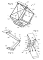
- pantographs 1a ', 1b' and 1c 'of different structures are shown, the structures / principles of which can be taken up for the realization of the articulated pantograph member of the invention.
- the schematized pantograph 1a is of diamond type. It comprises a frame 21 on which are articulated four lower arms 12a, 12b, 12c, 12d, parallel in pairs: 12a parallel to 12b and 12c parallel to 12d, and opposite two by two: 12a opposite 12c and 12b opposite 12d .
- At the upper end of each lower arm is articulated an upper arm corresponding to: for 12a the upper arm 13a, for 12b the upper arm 13b, for 12c the upper arm 13c and for 12d the upper arm 13d.
- the four upper arms 13a, 13b, 13c, 13d are parallel in pairs: 13a parallel to 13b and 13c parallel to 13d, and opposed in pairs: 13a opposite 13c and 13b opposite 13d.
- the upper ends of the four upper arms 13a, 13b, 13c, 13d are hinged to a plate 20.
- Discontinuous lines have been drawn to represent the axes of the joints.
- Reinforcing rods 22 make it possible to keep the arms parallel to each other in the folded (flattened) or unfolded (as shown) position of the pantograph 1a '.
- An actuator (not shown) makes it possible to deploy or fold the pantograph. Thanks to the arrangements and joints between the arms, the plate 20 can move in vertical translation when the pantograph folds or unfolds.
- the schematized pantograph 1b ' is of type Z.
- the pantograph Z 1b' rests on a frame 21 'on which are articulated, on the one hand, a lower arm 12' and, on the other hand, a counter-arm lower or lower connecting rod 15 '.
- An upper arm 13 'and an upper upper arm or upper link 16' are articulated to the lower arm 12 'and the lower arm / lower link 15'.
- a tray 20 ' is attached to the upper end of the pantograph.
- An actuator (not shown) makes it possible to actuate at the frame the arms and forearms / connecting rods to deploy or fold the pantograph. Thanks to the arrangements and joints between the arms and against arms / connecting rods, the plate 20 'can move in vertical translation when the pantograph folds or unfolds.
- the articulated members can be used in other applications than tunnel washing and, for example, wall painting, surface treatments (anti-foam, water-repellent, etc.), or for the analysis of surface (video for example to see the state of the works).
- the tools carried by the articulated members can be of the most various, organs of washing, tools of painting, of stripping, of observation, of measurement ...
- the works, besides the tunnels, can be vaults of bridges, sound walls, building walls ...
- the articulated members may be conveyed by means other than a motor vehicle and, for example, a road trailer, a rail car or a rail car, a barge or a ship...
- the schematized pantograph 1c is scissor type in which the arms intersect at X being articulated to each other at the crossing.
- the pantograph may comprise one or more stages of X-arms, articulated between them between each floor.
- a pair of intersecting arms X, 23a 24a (first element of the pair) and 23b 24b (second element of the pair) are mounted parallel between a support 21 at the bottom and a plate 27 at the top.
- the lower ends of the arms 24a and 24b are fixed hinged to the support 21.
- the upper ends of the arms 23a and 23b are fixed hinged to the plate 27.
- the lower ends of the arms 23a and 23b and the upper ends of the arms 24a and 24b are provided with rolling means to be able to move on the support 21 and under the plate 27.
- a jack 25 makes it possible to move the arms to raise or lower the plate 27.
- a Z-type pantograph is used and, in a simplified embodiment, a pantograph of the type used for current sensing on the electric locomotives and modified for the present application and for which a long time is required. experience is available.
- the metal pantographs and not just tubes were used for the Z pantograph arms.
- the articulated members with washing members are mounted on a truck-type motor vehicle 10 and, more particularly, on a rear chassis of a semitrailer.
- the articulated members with washing members are mounted on a chassis which is removable from the vehicle 10, that is to say that the chassis can be mounted or removed from the vehicle.
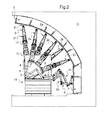
- the articulated members 2a-2h are all deployed so that the washing bodies 3 of the rotating roller type (the means for spraying water and / or washing substance are not shown to simplify the figures) can be applied to the wall of the tunnel 11 covering their respective paths so that a given arcuate surface of the wall is washed over the entire arc in a single pass and avoiding leaving unwashed strips in said arc.
- the washing bodies 3 of the rotating roller type the means for spraying water and / or washing substance are not shown to simplify the figures
- the support 4 is a tilting support in arc or triangle 4 common to several articulated members having a general shape disc segment, the tip of the disc segment comprising a bearing rotating about the axis of tilting.
- the articulated members are fixed on the outer edge of the disc segment in offset angular positions, this outer edge having plates for fixing said articulated members and thus having a faceted diamond shape.
- the support 4 in the form of a diamond section is a simple frame whose tip comprises a joint and whose tilting axis 28 is along the length of the vehicle and whose tilting is provided by jacks double effect 7.
- the support 4 is disposed in a cradle 29 fixed between the two edges of which it can rock cradle.
- the support 5 is a simple tilting support 5 for a single articulated member, or even two 2d 2nd members as in the example shown.
- the single support is of linear type and can move over the width of the vehicle.
- the supports are of the type tilting and linear type.
- the pantograph 1b is actuated by one or more double-acting cylinders for folding or unfolding. In the folded position, the arms of the pantographs are brought to meet by the action of double effect cylinders also, conversely, to move them in unfolded positions.
- the retractable arm 9 can switch between a fixed working position in which the contribution of the retractable arm in the height / length of the articulated member is maximum, and a retracted position.
- the retractable arm 9 allows the distal portion of the articulated member and more particularly to its washing member, to retract / fade when it hits an obstacle.
- a passive spring retraction system can be implemented or, in more advanced variants, active with force or shock sensors and cylinders.
- manual control means and / or automated also allow the retraction / erasure of the retractable arm 9 without direct contact with an obstacle but preventively to shock.
- actuating means of the jack type are used.
- the joint joint 8 allows movements of the washing member relative to the retractable arm and, preferably, in a plane perpendicular to the axis of movement of the vehicle, the latter axis being parallel to the main axis of the work, in this example a tunnel.
- the joint may comprise passive restoring means, such as springs, or active, of the jack type.
- the washing member 3 is here rotating brush type with jets (not shown).
- each cylinder or part thereof may be manual, but preferably a part of the control or a control check, each cylinder is automated in such a way that dangerous or excessive controls do not occur. endanger equipment or even personnel.
- force sensors can detect excessive forces or shocks preventing dangerous commands or, better, allowing to retract or at least partially fold the articulated member.
- access to the platform preferably constituted by a removable chassis of the vehicle and carrying the articulated members can be secured by preventing access or by blocking any member control, or even the movement of the vehicle in case of presence human. It is indeed better to avoid that the retraction of a member, see the retraction of an arm does not come to hurt a person present on the platform of the vehicle.
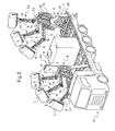
- Figures 4a , 4b and 5 make it possible to better distinguish the articulated members 2f, 2g, 2h and their common rocking support 4 as well as the other organs that are useful for washing and in particular the liquid washing reserve 6.
- Figure 4a and 4b the retractable chassis has been removed from the vehicle and, Figure 4a , the articulated limbs are in working position and, Figure 4b , in the rest position.
- the energy necessary for the operation of this assembly is provided by the motor of the self-propelled vehicle.
- an energy generator is installed on the chassis carrying the articulated members.
- FIGS. 6 to 8 allow to better visualize an articulated member, in this example the 2a, with its washing member 3 brush-type elongate brush at the distal end.
- the articulated limb is retracted and its height is minimal. It is also compactly retracted because the washing member is arranged in such a way that the axis of the roll is substantially parallel to the arms of the articulated member.
- the pantograph 1b is folded and the retractable arm 9 is in its folded position.
- the articulated limb 2a has between its proximal end, at the bottom of the Figure 6 , and its distal end: the pantograph 1b consists of a lower main arm 12 and an upper main arm 13 hinged to the previous one and with their lower arms / rods lower / e 15 and greater / e 16 respective / ves, then a retractable arm 9 hinged to said pantograph, then the articulation joint 8 and finally the washing member 3.
- These arms are actuated by cylinders 14 double effect to retract or deploy the articulated member by acting on the pantograph 1b or on the retractable arm 9.
- the articulated member 2a has encountered an obstacle (not shown) at its washing member 3 and the retractable arm 9 has retracted, rolling back and down the washing member.
- the term "backward" means that the washing member is in a direction opposite to the direction of movement of the washing vehicle so as not to withstand the obstacle encountered during the advance of the vehicle.
- the retraction of the retractable arm is to the rear, in the opposite direction of the movement of the vehicle carrying the articulated member.
- the retraction is active in that when obstacle sensors have detected an obstacle, they control the cylinders 14 of the retractable arm to cause the retraction.
- passive spring retraction means may be used alone or in addition to the active control cylinders.
- the latter can, in addition, control the cylinders 14 of the pantograph 1b to fold the pantograph.
- the lower main arm 12 and its lower arm / connecting rod / e 15 are perforated plates, as the upper main arm 13.
- the counter arm 16 of the upper main arm 13 consists of two rods.
- the operation of this pantograph 1b is similar to that of the pantograph 1b 'presented above.
- the retractable arm 9 is, in turn, articulated along the axis 18 at the distal end of the pantograph 1b.
- automated control means with optical sensors can detect an obstacle , For example a billboard or a fan, before a washing member, or even an arm / arm of an articulated member does not come to hit it.
- These optical means use cameras and allow distance measurements in their common field of vision.
- More conventional obstacle detection control means may be used in addition / redundancy of the above or used alone.
- These means can implement obstacle sensors / distance measurement, preferably ultrasound, contact detection poles ...
- stress sensors can be installed on certain joints to detect shocks.
- control means are of mixed type, that is to say both manual and automated.
- the rise and placement of the washing member of each articulated member is done manually and the obstacle detection is done automatically, an operator can however manually ensure the descent and / or the retraction of the organ washing if he wishes.
- the control means for their automated part are disengageable to go into full manual control if necessary.
- the chassis carrying the articulated members is disposed inside a standardized cargo transport container whose walls are removable in order to release the articulated members so that they can operate.
- the folded articulated members are protected by the container walls put back in place to close it.
Landscapes
- Engineering & Computer Science (AREA)
- Architecture (AREA)
- Civil Engineering (AREA)
- Structural Engineering (AREA)
- Current-Collector Devices For Electrically Propelled Vehicles (AREA)
- Lining And Supports For Tunnels (AREA)
- Cleaning In General (AREA)
Applications Claiming Priority (1)
| Application Number | Priority Date | Filing Date | Title |
|---|---|---|---|
| FR1260244A FR2997424B1 (fr) | 2012-10-26 | 2012-10-26 | Membre articule comportant un outil de traitement de parois et vehicule de traitement de parois d'un ouvrage |
Publications (3)
| Publication Number | Publication Date |
|---|---|
| EP2725141A2 true EP2725141A2 (de) | 2014-04-30 |
| EP2725141A3 EP2725141A3 (de) | 2016-04-20 |
| EP2725141B1 EP2725141B1 (de) | 2017-11-22 |
Family
ID=47598921
Family Applications (1)
| Application Number | Title | Priority Date | Filing Date |
|---|---|---|---|
| EP13306474.1A Active EP2725141B1 (de) | 2012-10-26 | 2013-10-25 | Mit Gelenken ausgestattetes Glied, das mit einem Wandbehandlungswerkzeug ausgestattet ist, und Fahrzeug zur Wandbehandlung eines Bauwerks |
Country Status (2)
| Country | Link |
|---|---|
| EP (1) | EP2725141B1 (de) |
| FR (1) | FR2997424B1 (de) |
Cited By (2)
| Publication number | Priority date | Publication date | Assignee | Title |
|---|---|---|---|---|
| CN105256748A (zh) * | 2015-11-10 | 2016-01-20 | 山东汇强重工科技有限公司 | 一种多功能清洗车 |
| CN107620601A (zh) * | 2017-10-13 | 2018-01-23 | 湖南五新隧道智能装备股份有限公司 | 防水施工用旋转折叠臂组及包含此臂组的防水施工用台车 |
Families Citing this family (1)
| Publication number | Priority date | Publication date | Assignee | Title |
|---|---|---|---|---|
| CN105887737B (zh) * | 2016-06-02 | 2017-09-05 | 重庆交通大学 | 隧道侧壁清洗机 |
Family Cites Families (4)
| Publication number | Priority date | Publication date | Assignee | Title |
|---|---|---|---|---|
| FR2584747B1 (fr) * | 1985-07-12 | 1987-12-04 | Materiel De Voirie | Vehicule pour le nettoyage de la voirie, en particulier des parois de tunnels, passages souterrains et similaires |
| DE4423376A1 (de) * | 1994-07-04 | 1996-01-18 | Maschbau & Umwelttech Gmbh | Fahrzeug zum Strahlen von ebenen, gekrümmten und strukturierten Flächen |
| IT1406298B1 (it) * | 2010-11-02 | 2014-02-14 | S I M I N S P A | Apparecchiatura per spruzzare sostanze liquide, quali vernici o acqua, sulle pareti interne di gallerie |
| DE202011001292U1 (de) * | 2011-01-10 | 2011-03-10 | MULAG FAHRZEUGWERK Heinz Wössner GmbH & Co. KG | Tunnelwaschfahrzeug |
-
2012
- 2012-10-26 FR FR1260244A patent/FR2997424B1/fr active Active
-
2013
- 2013-10-25 EP EP13306474.1A patent/EP2725141B1/de active Active
Cited By (3)
| Publication number | Priority date | Publication date | Assignee | Title |
|---|---|---|---|---|
| CN105256748A (zh) * | 2015-11-10 | 2016-01-20 | 山东汇强重工科技有限公司 | 一种多功能清洗车 |
| CN107620601A (zh) * | 2017-10-13 | 2018-01-23 | 湖南五新隧道智能装备股份有限公司 | 防水施工用旋转折叠臂组及包含此臂组的防水施工用台车 |
| CN107620601B (zh) * | 2017-10-13 | 2023-09-05 | 湖南五新隧道智能装备股份有限公司 | 防水施工用旋转折叠臂组及包含此臂组的防水施工用台车 |
Also Published As
| Publication number | Publication date |
|---|---|
| FR2997424B1 (fr) | 2017-04-07 |
| EP2725141B1 (de) | 2017-11-22 |
| FR2997424A1 (fr) | 2014-05-02 |
| EP2725141A3 (de) | 2016-04-20 |
Similar Documents
| Publication | Publication Date | Title |
|---|---|---|
| EP3286128B1 (de) | Arbeitsbühne mit schlagloch-schutz | |
| EP0733584B1 (de) | Automatische Aufrichtvorrichtung für einen Kran mit zusammenklappbarem Ausleger | |
| US9834423B2 (en) | Lift truck equipped with stabilizer means | |
| EP2725141B1 (de) | Mit Gelenken ausgestattetes Glied, das mit einem Wandbehandlungswerkzeug ausgestattet ist, und Fahrzeug zur Wandbehandlung eines Bauwerks | |
| EP0945551B1 (de) | Kehrvorrichtung für Arbeitsfahrzeuge | |
| WO2016116688A1 (fr) | Navire à passerelle télescopique de transfert de personnes entre le navire et un objet stationnaire ou quasiment stationnaire en mer, tel qu'une éolienne | |
| US12246678B2 (en) | Mounted retractable catwalk for trucks, utility, construction, and industrial vehicles and equipment | |
| EP3377716B1 (de) | Zusammenlegbare unterstandsstruktur | |
| FR2904182A1 (fr) | Faucheuse attelable tractee avec dispositif de commande de l'inclinaison d'unites de fauchage. | |
| FR2607029A1 (fr) | Dispositif de traitement polyvalent, en particulier pour l'entretien des vignes, et vehicule tracteur ou engin tractable equipe d'un ou de plusieurs de ces dispositifs | |
| JP4537897B2 (ja) | 草刈機 | |
| WO2009034272A2 (fr) | Dispositif elevateur pour fauteuil roulant | |
| WO2017098122A1 (fr) | Ensemble de propulsion d'aeronef equipe de marches permettant a un operateur d'atteindre sa portion superieure | |
| EP3070203B1 (de) | Be-, entlade- und aufsetzsystem einer schienenweiche auf ein bahngleis | |
| JP4105969B2 (ja) | 梯子車 | |
| US12214748B2 (en) | Angle folded egress ladder | |
| FR2958637A1 (fr) | Dispositif de pose de plaques, notamment de plaques anti-incendie | |
| FR2786454A1 (fr) | Hayon elevateur retractable | |
| FR3140733A1 (fr) | Machine agricole repliable avec une partie et un composant reliés cinématiquement entre eux | |
| EP1609449A2 (de) | Kraftfahrzeug für Körperbehinderte | |
| FR2641029A1 (de) | ||
| FR2903095A1 (fr) | Dispositif de lest mobile pour grue a tour transportable | |
| JP4406526B2 (ja) | 高所作業車 | |
| JP5546393B2 (ja) | 荷受台昇降装置 | |
| WO2014177795A1 (fr) | Vehicule equipe d'un dispositif de protection d'ouvrant assurant une optimisation du gabarit d'ouverture |
Legal Events
| Date | Code | Title | Description |
|---|---|---|---|
| PUAI | Public reference made under article 153(3) epc to a published international application that has entered the european phase |
Free format text: ORIGINAL CODE: 0009012 |
|
| 17P | Request for examination filed |
Effective date: 20131025 |
|
| AK | Designated contracting states |
Kind code of ref document: A2 Designated state(s): AL AT BE BG CH CY CZ DE DK EE ES FI FR GB GR HR HU IE IS IT LI LT LU LV MC MK MT NL NO PL PT RO RS SE SI SK SM TR |
|
| AX | Request for extension of the european patent |
Extension state: BA ME |
|
| PUAL | Search report despatched |
Free format text: ORIGINAL CODE: 0009013 |
|
| AK | Designated contracting states |
Kind code of ref document: A3 Designated state(s): AL AT BE BG CH CY CZ DE DK EE ES FI FR GB GR HR HU IE IS IT LI LT LU LV MC MK MT NL NO PL PT RO RS SE SI SK SM TR |
|
| AX | Request for extension of the european patent |
Extension state: BA ME |
|
| RIC1 | Information provided on ipc code assigned before grant |
Ipc: E01H 1/00 20060101AFI20160315BHEP |
|
| 17P | Request for examination filed |
Effective date: 20160525 |
|
| RBV | Designated contracting states (corrected) |
Designated state(s): AL AT BE BG CH CY CZ DE DK EE ES FI FR GB GR HR HU IE IS IT LI LT LU LV MC MK MT NL NO PL PT RO RS SE SI SK SM TR |
|
| 17Q | First examination report despatched |
Effective date: 20161004 |
|
| STAA | Information on the status of an ep patent application or granted ep patent |
Free format text: STATUS: EXAMINATION IS IN PROGRESS |
|
| GRAP | Despatch of communication of intention to grant a patent |
Free format text: ORIGINAL CODE: EPIDOSNIGR1 |
|
| STAA | Information on the status of an ep patent application or granted ep patent |
Free format text: STATUS: GRANT OF PATENT IS INTENDED |
|
| INTG | Intention to grant announced |
Effective date: 20170816 |
|
| GRAS | Grant fee paid |
Free format text: ORIGINAL CODE: EPIDOSNIGR3 |
|
| GRAA | (expected) grant |
Free format text: ORIGINAL CODE: 0009210 |
|
| STAA | Information on the status of an ep patent application or granted ep patent |
Free format text: STATUS: THE PATENT HAS BEEN GRANTED |
|
| AK | Designated contracting states |
Kind code of ref document: B1 Designated state(s): AL AT BE BG CH CY CZ DE DK EE ES FI FR GB GR HR HU IE IS IT LI LT LU LV MC MK MT NL NO PL PT RO RS SE SI SK SM TR |
|
| REG | Reference to a national code |
Ref country code: GB Ref legal event code: FG4D Free format text: NOT ENGLISH |
|
| REG | Reference to a national code |
Ref country code: CH Ref legal event code: EP |
|
| REG | Reference to a national code |
Ref country code: IE Ref legal event code: FG4D Free format text: LANGUAGE OF EP DOCUMENT: FRENCH |
|
| REG | Reference to a national code |
Ref country code: AT Ref legal event code: REF Ref document number: 948521 Country of ref document: AT Kind code of ref document: T Effective date: 20171215 |
|
| REG | Reference to a national code |
Ref country code: DE Ref legal event code: R096 Ref document number: 602013029719 Country of ref document: DE |
|
| REG | Reference to a national code |
Ref country code: CH Ref legal event code: NV Representative=s name: JACOBACCI CORALIS HARLE C/O JACOBACCI AND PART, CH |
|
| REG | Reference to a national code |
Ref country code: NL Ref legal event code: MP Effective date: 20171122 |
|
| REG | Reference to a national code |
Ref country code: LT Ref legal event code: MG4D |
|
| PG25 | Lapsed in a contracting state [announced via postgrant information from national office to epo] |
Ref country code: FI Free format text: LAPSE BECAUSE OF FAILURE TO SUBMIT A TRANSLATION OF THE DESCRIPTION OR TO PAY THE FEE WITHIN THE PRESCRIBED TIME-LIMIT Effective date: 20171122 Ref country code: ES Free format text: LAPSE BECAUSE OF FAILURE TO SUBMIT A TRANSLATION OF THE DESCRIPTION OR TO PAY THE FEE WITHIN THE PRESCRIBED TIME-LIMIT Effective date: 20171122 Ref country code: SE Free format text: LAPSE BECAUSE OF FAILURE TO SUBMIT A TRANSLATION OF THE DESCRIPTION OR TO PAY THE FEE WITHIN THE PRESCRIBED TIME-LIMIT Effective date: 20171122 Ref country code: NL Free format text: LAPSE BECAUSE OF FAILURE TO SUBMIT A TRANSLATION OF THE DESCRIPTION OR TO PAY THE FEE WITHIN THE PRESCRIBED TIME-LIMIT Effective date: 20171122 Ref country code: NO Free format text: LAPSE BECAUSE OF FAILURE TO SUBMIT A TRANSLATION OF THE DESCRIPTION OR TO PAY THE FEE WITHIN THE PRESCRIBED TIME-LIMIT Effective date: 20180222 Ref country code: LT Free format text: LAPSE BECAUSE OF FAILURE TO SUBMIT A TRANSLATION OF THE DESCRIPTION OR TO PAY THE FEE WITHIN THE PRESCRIBED TIME-LIMIT Effective date: 20171122 |
|
| PG25 | Lapsed in a contracting state [announced via postgrant information from national office to epo] |
Ref country code: HR Free format text: LAPSE BECAUSE OF FAILURE TO SUBMIT A TRANSLATION OF THE DESCRIPTION OR TO PAY THE FEE WITHIN THE PRESCRIBED TIME-LIMIT Effective date: 20171122 Ref country code: BG Free format text: LAPSE BECAUSE OF FAILURE TO SUBMIT A TRANSLATION OF THE DESCRIPTION OR TO PAY THE FEE WITHIN THE PRESCRIBED TIME-LIMIT Effective date: 20180222 Ref country code: RS Free format text: LAPSE BECAUSE OF FAILURE TO SUBMIT A TRANSLATION OF THE DESCRIPTION OR TO PAY THE FEE WITHIN THE PRESCRIBED TIME-LIMIT Effective date: 20171122 Ref country code: GR Free format text: LAPSE BECAUSE OF FAILURE TO SUBMIT A TRANSLATION OF THE DESCRIPTION OR TO PAY THE FEE WITHIN THE PRESCRIBED TIME-LIMIT Effective date: 20180223 Ref country code: LV Free format text: LAPSE BECAUSE OF FAILURE TO SUBMIT A TRANSLATION OF THE DESCRIPTION OR TO PAY THE FEE WITHIN THE PRESCRIBED TIME-LIMIT Effective date: 20171122 |
|
| PG25 | Lapsed in a contracting state [announced via postgrant information from national office to epo] |
Ref country code: CY Free format text: LAPSE BECAUSE OF FAILURE TO SUBMIT A TRANSLATION OF THE DESCRIPTION OR TO PAY THE FEE WITHIN THE PRESCRIBED TIME-LIMIT Effective date: 20171122 Ref country code: EE Free format text: LAPSE BECAUSE OF FAILURE TO SUBMIT A TRANSLATION OF THE DESCRIPTION OR TO PAY THE FEE WITHIN THE PRESCRIBED TIME-LIMIT Effective date: 20171122 Ref country code: CZ Free format text: LAPSE BECAUSE OF FAILURE TO SUBMIT A TRANSLATION OF THE DESCRIPTION OR TO PAY THE FEE WITHIN THE PRESCRIBED TIME-LIMIT Effective date: 20171122 Ref country code: DK Free format text: LAPSE BECAUSE OF FAILURE TO SUBMIT A TRANSLATION OF THE DESCRIPTION OR TO PAY THE FEE WITHIN THE PRESCRIBED TIME-LIMIT Effective date: 20171122 Ref country code: SK Free format text: LAPSE BECAUSE OF FAILURE TO SUBMIT A TRANSLATION OF THE DESCRIPTION OR TO PAY THE FEE WITHIN THE PRESCRIBED TIME-LIMIT Effective date: 20171122 |
|
| REG | Reference to a national code |
Ref country code: DE Ref legal event code: R097 Ref document number: 602013029719 Country of ref document: DE |
|
| PG25 | Lapsed in a contracting state [announced via postgrant information from national office to epo] |
Ref country code: PL Free format text: LAPSE BECAUSE OF FAILURE TO SUBMIT A TRANSLATION OF THE DESCRIPTION OR TO PAY THE FEE WITHIN THE PRESCRIBED TIME-LIMIT Effective date: 20171122 Ref country code: SM Free format text: LAPSE BECAUSE OF FAILURE TO SUBMIT A TRANSLATION OF THE DESCRIPTION OR TO PAY THE FEE WITHIN THE PRESCRIBED TIME-LIMIT Effective date: 20171122 Ref country code: RO Free format text: LAPSE BECAUSE OF FAILURE TO SUBMIT A TRANSLATION OF THE DESCRIPTION OR TO PAY THE FEE WITHIN THE PRESCRIBED TIME-LIMIT Effective date: 20171122 Ref country code: IT Free format text: LAPSE BECAUSE OF FAILURE TO SUBMIT A TRANSLATION OF THE DESCRIPTION OR TO PAY THE FEE WITHIN THE PRESCRIBED TIME-LIMIT Effective date: 20171122 |
|
| PG25 | Lapsed in a contracting state [announced via postgrant information from national office to epo] |
Ref country code: MT Free format text: LAPSE BECAUSE OF FAILURE TO SUBMIT A TRANSLATION OF THE DESCRIPTION OR TO PAY THE FEE WITHIN THE PRESCRIBED TIME-LIMIT Effective date: 20171122 |
|
| PLBE | No opposition filed within time limit |
Free format text: ORIGINAL CODE: 0009261 |
|
| STAA | Information on the status of an ep patent application or granted ep patent |
Free format text: STATUS: NO OPPOSITION FILED WITHIN TIME LIMIT |
|
| 26N | No opposition filed |
Effective date: 20180823 |
|
| PG25 | Lapsed in a contracting state [announced via postgrant information from national office to epo] |
Ref country code: SI Free format text: LAPSE BECAUSE OF FAILURE TO SUBMIT A TRANSLATION OF THE DESCRIPTION OR TO PAY THE FEE WITHIN THE PRESCRIBED TIME-LIMIT Effective date: 20171122 |
|
| PGFP | Annual fee paid to national office [announced via postgrant information from national office to epo] |
Ref country code: AT Payment date: 20180906 Year of fee payment: 6 |
|
| REG | Reference to a national code |
Ref country code: DE Ref legal event code: R119 Ref document number: 602013029719 Country of ref document: DE |
|
| REG | Reference to a national code |
Ref country code: CH Ref legal event code: PCOW Free format text: NEW ADDRESS: 1, RUE DU COLONEL PIERRE AVIA, 75015 PARIS (FR) |
|
| GBPC | Gb: european patent ceased through non-payment of renewal fee |
Effective date: 20181025 |
|
| REG | Reference to a national code |
Ref country code: BE Ref legal event code: MM Effective date: 20181031 |
|
| PG25 | Lapsed in a contracting state [announced via postgrant information from national office to epo] |
Ref country code: MC Free format text: LAPSE BECAUSE OF FAILURE TO SUBMIT A TRANSLATION OF THE DESCRIPTION OR TO PAY THE FEE WITHIN THE PRESCRIBED TIME-LIMIT Effective date: 20171122 Ref country code: LU Free format text: LAPSE BECAUSE OF NON-PAYMENT OF DUE FEES Effective date: 20181025 |
|
| REG | Reference to a national code |
Ref country code: IE Ref legal event code: MM4A |
|
| PG25 | Lapsed in a contracting state [announced via postgrant information from national office to epo] |
Ref country code: DE Free format text: LAPSE BECAUSE OF NON-PAYMENT OF DUE FEES Effective date: 20190501 |
|
| PG25 | Lapsed in a contracting state [announced via postgrant information from national office to epo] |
Ref country code: BE Free format text: LAPSE BECAUSE OF NON-PAYMENT OF DUE FEES Effective date: 20181031 Ref country code: FR Free format text: LAPSE BECAUSE OF NON-PAYMENT OF DUE FEES Effective date: 20181031 |
|
| PG25 | Lapsed in a contracting state [announced via postgrant information from national office to epo] |
Ref country code: IE Free format text: LAPSE BECAUSE OF NON-PAYMENT OF DUE FEES Effective date: 20181025 Ref country code: GB Free format text: LAPSE BECAUSE OF NON-PAYMENT OF DUE FEES Effective date: 20181025 |
|
| PG25 | Lapsed in a contracting state [announced via postgrant information from national office to epo] |
Ref country code: TR Free format text: LAPSE BECAUSE OF FAILURE TO SUBMIT A TRANSLATION OF THE DESCRIPTION OR TO PAY THE FEE WITHIN THE PRESCRIBED TIME-LIMIT Effective date: 20171122 |
|
| PG25 | Lapsed in a contracting state [announced via postgrant information from national office to epo] |
Ref country code: PT Free format text: LAPSE BECAUSE OF FAILURE TO SUBMIT A TRANSLATION OF THE DESCRIPTION OR TO PAY THE FEE WITHIN THE PRESCRIBED TIME-LIMIT Effective date: 20171122 |
|
| PG25 | Lapsed in a contracting state [announced via postgrant information from national office to epo] |
Ref country code: MK Free format text: LAPSE BECAUSE OF NON-PAYMENT OF DUE FEES Effective date: 20171122 Ref country code: HU Free format text: LAPSE BECAUSE OF FAILURE TO SUBMIT A TRANSLATION OF THE DESCRIPTION OR TO PAY THE FEE WITHIN THE PRESCRIBED TIME-LIMIT; INVALID AB INITIO Effective date: 20131025 |
|
| PG25 | Lapsed in a contracting state [announced via postgrant information from national office to epo] |
Ref country code: AL Free format text: LAPSE BECAUSE OF FAILURE TO SUBMIT A TRANSLATION OF THE DESCRIPTION OR TO PAY THE FEE WITHIN THE PRESCRIBED TIME-LIMIT Effective date: 20171122 Ref country code: IS Free format text: LAPSE BECAUSE OF FAILURE TO SUBMIT A TRANSLATION OF THE DESCRIPTION OR TO PAY THE FEE WITHIN THE PRESCRIBED TIME-LIMIT Effective date: 20180322 |
|
| REG | Reference to a national code |
Ref country code: AT Ref legal event code: MM01 Ref document number: 948521 Country of ref document: AT Kind code of ref document: T Effective date: 20191025 |
|
| PG25 | Lapsed in a contracting state [announced via postgrant information from national office to epo] |
Ref country code: AT Free format text: LAPSE BECAUSE OF NON-PAYMENT OF DUE FEES Effective date: 20191025 |
|
| P01 | Opt-out of the competence of the unified patent court (upc) registered |
Effective date: 20230523 |
|
| REG | Reference to a national code |
Ref country code: CH Ref legal event code: U11 Free format text: ST27 STATUS EVENT CODE: U-0-0-U10-U11 (AS PROVIDED BY THE NATIONAL OFFICE) Effective date: 20251101 |
|
| PGFP | Annual fee paid to national office [announced via postgrant information from national office to epo] |
Ref country code: CH Payment date: 20251101 Year of fee payment: 13 |