EP2730506A2 - Electrical power transfer system for propeller system - Google Patents
Electrical power transfer system for propeller system Download PDFInfo
- Publication number
- EP2730506A2 EP2730506A2 EP13192065.4A EP13192065A EP2730506A2 EP 2730506 A2 EP2730506 A2 EP 2730506A2 EP 13192065 A EP13192065 A EP 13192065A EP 2730506 A2 EP2730506 A2 EP 2730506A2
- Authority
- EP
- European Patent Office
- Prior art keywords
- slip ring
- propeller
- assembly
- brush block
- slip
- Prior art date
- Legal status (The legal status is an assumption and is not a legal conclusion. Google has not performed a legal analysis and makes no representation as to the accuracy of the status listed.)
- Granted
Links
Images


Classifications
-
- B—PERFORMING OPERATIONS; TRANSPORTING
- B64—AIRCRAFT; AVIATION; COSMONAUTICS
- B64D—EQUIPMENT FOR FITTING IN OR TO AIRCRAFT; FLIGHT SUITS; PARACHUTES; ARRANGEMENT OR MOUNTING OF POWER PLANTS OR PROPULSION TRANSMISSIONS IN AIRCRAFT
- B64D15/00—De-icing or preventing icing on exterior surfaces of aircraft
- B64D15/12—De-icing or preventing icing on exterior surfaces of aircraft by electric heating
-
- F—MECHANICAL ENGINEERING; LIGHTING; HEATING; WEAPONS; BLASTING
- F01—MACHINES OR ENGINES IN GENERAL; ENGINE PLANTS IN GENERAL; STEAM ENGINES
- F01D—NON-POSITIVE DISPLACEMENT MACHINES OR ENGINES, e.g. STEAM TURBINES
- F01D25/00—Component parts, details, or accessories, not provided for in, or of interest apart from, other groups
- F01D25/02—De-icing means for engines having icing phenomena
-
- B—PERFORMING OPERATIONS; TRANSPORTING
- B64—AIRCRAFT; AVIATION; COSMONAUTICS
- B64C—AEROPLANES; HELICOPTERS
- B64C11/00—Propellers, e.g. of ducted type; Features common to propellers and rotors for rotorcraft
- B64C11/02—Hub construction
-
- B—PERFORMING OPERATIONS; TRANSPORTING
- B64—AIRCRAFT; AVIATION; COSMONAUTICS
- B64D—EQUIPMENT FOR FITTING IN OR TO AIRCRAFT; FLIGHT SUITS; PARACHUTES; ARRANGEMENT OR MOUNTING OF POWER PLANTS OR PROPULSION TRANSMISSIONS IN AIRCRAFT
- B64D35/00—Transmitting power from power plants to propellers or rotors; Arrangements of transmissions
Definitions
- FIG. 2 is a cross-sectional view of an embodiment of a slip ring arrangement for a propeller system
Landscapes
- Engineering & Computer Science (AREA)
- Aviation & Aerospace Engineering (AREA)
- Mechanical Engineering (AREA)
- General Engineering & Computer Science (AREA)
- Motor Or Generator Current Collectors (AREA)
Abstract
Description
- The subject matter disclosed herein generally relates to propeller-equipped craft. More specifically, the subject disclosure relates to transfer of electrical power to propeller mounted components of the propeller-equipped craft.
- A typical rotor or propeller equipped craft is often equipped with components at the rotating rotor such as deicing components, which require electrical power for operation. The deicing components typically include heating elements embedded into the propeller blades. Wires carry electrical power to the heating elements when deicing is required. The heating elements then melt accumulated ice and prevent subsequent formation of ice of the propeller blade surfaces. To transfer electrical power from the rotationally fixed airframe of the aircraft to the rotating propeller, a plate rotating with the rotor is provided and one or more slip rings are mounted to it. The rotating slip rings interfaces with a stationary brush block mounted to a front cover of a reduction gear box for the engine driving the propeller. In the aircraft, the brush block interfaces with a vertical face of the plate containing the slip rings forward of the gearbox. Lead wires from studs attached to the slip rings distribute electrical power to the various rotating components. Due to the necessary size of the slip rings, the presence of fluids and abrasive materials such as sand and dust in the brush block environment, a high level of wear occurs in the brush blocks carbon brushes and in the slip rings, resulting in excessive amounts of maintenance to repair and/or replace the brush block and slip ring components.
- According to one aspect of the invention, a propeller system for an aircraft includes a propeller assembly rotatable about a central axis and a reduction gearbox operably connected to the propeller assembly via a propeller shaft. An electrical power transfer system is positioned such that the gearbox is located axially between the electrical power transfer system and the propeller assembly. The electrical power transfer system includes a slip ring assembly operably connected to an oil transfer tube extending to the propeller assembly and a brush block interactive with the slip ring assembly to transfer electrical power to a plurality of lead wires extending from the slip ring assembly to the propeller assembly. The brush block is positioned such that brush block tips of the brush block extend toward the slip ring assembly in a substantially axial direction relative to the central axis.
- According to another aspect of the invention, a deicing system for a propeller assembly includes a heating element operably connected to a propeller blade of the propeller assembly. A brush block is positioned such that a reduction gearbox operably connected to the propeller assembly is located between the brush block and the propeller assembly. A slip ring assembly is secured to a rotating element and interactive with the brush block to transfer electrical power from the brush block assembly to the heating element via a plurality of lead wires extending from the slip ring assembly to the heating element. The brush block is positioned such that brush block tips of the brush block extend toward the slip ring assembly in a substantially axial direction relative to a central axis of the propeller assembly.
- These and other advantages and features will become more apparent from the following description taken in conjunction with the drawings.
- The subject matter, which is regarded as the invention, is particularly pointed out and distinctly claimed in the claims at the conclusion of the specification. The foregoing and other features, and advantages of the invention are apparent from the following detailed description taken in conjunction with the accompanying drawings in which:
-
FIG. 1 is a schematic view of an embodiment of a propeller system; -
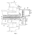
FIG. 2 is a cross-sectional view of an embodiment of a slip ring arrangement for a propeller system; -
FIG. 3 is a schematic view of another embodiment of a propeller system; and -
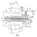
FIG. 4 is a cross-sectional view of another embodiment of a slip ring arrangement for a propeller system. - The detailed description explains embodiments of the invention, together with advantages and features, by way of example with reference to the drawings.
- Shown in
FIG. 1 is schematic view of an embodiment of apropeller system 10 for an aircraft. Thepropeller system 10 includes a propeller assembly having a plurality ofpropeller blades 12 arranged around ahub 14. Apitch change actuator 11 is connected to an end of thehub 14. Thepropeller blades 12 include one ormore heating elements 30 for deicing of thepropeller blades 12. Thepropeller system 10 is operably connected to areduction gearbox 16 via apropeller shaft 18, which is in turn connected to anengine 20. Thereduction gearbox 16 translates a rotational speed of theengine 20 into a selected propeller speed, Np. - Referring now to
FIG. 2 , thepropeller shaft 18 is supported byshaft bearings 22. Further, one or more tubes, for example,oil transfer tube 24 extend alongshaft axis 28 toward thepropeller blades 12. Theoil transfer tube 24 is supported by thepitch change actuator 11 and interfaces with a transfer bearing 32 to provide fluid to pitchchange actuator 11 at thehub 14. Abrush block 34 is located at an aft side of thegearbox 16, in other words thegearbox 16 is located between thepropeller blades 12 and thebrush block 34, relative to theshaft axis 28. Thebrush block 34 is at least partially supported by and enclosed in abrush block housing 36. In some embodiments, thebrush block 34 is secured to anaft gearbox face 38. - In the embodiment of
FIG. 2 , theoil transfer tube 24 includes aslip ring assembly 40. Theslip ring assembly 40 includes aslip ring plate 54, with theslip rings 42 molded into or assembled to aplate face 56 of theslip ring plate 54. Theslip ring plate 54 is concentric with and secured to theoil transfer tube 24 rearward of thegearbox 16. In some embodiments, theslip ring assembly 40 includes threeslip rings 42. Thebrush block 34 includes a number ofbrush block tips 46, which interface with theslip rings 42. Thebrush block 34 receives electrical power from a power source, for example, generator 48, and transfers the electrical power to theslip rings 42 via thebrush block tips 46. In the embodiment ofFIG. 2 , thebrush block tips 46 extend substantially axially relative to theshaft axis 28 toward theslip rings 42. Thebrush block tips 46 may be shimmed into a selected location relative to theslip rings 42. A number oflead wires 50 extend from theslip rings 42. Thelead wires 50 are routed through awire transfer tube 52 installed into theoil transfer tube 24. Thewire transfer tube 52 rotates about theshaft axis 28 with theoil transfer tube 24 at Np. Thewire transfer tube 52 is isolated from oil flow through theoil transfer tube 24 to protect thelead wires 50 from damage due to the oil flow. - As shown in
FIG. 3 , thelead wires 50 exit thewire transfer tube 52 at thehub 14 and are routed to theheating elements 30 to provide power thereto for deicing of thepropeller blades 12. - In another embodiment, shown in
FIG. 4 , theslip ring plate 54 is assembled to aslip ring tube 44, which is supported byslip ring bearings 60 located at asupport shaft 62 extending from thebrush block housing 36 into an interior of theslip ring tube 44. Theslip ring assembly 40 is operably connected to theoil transfer tube 24 via a slipring drive tab 64 extending from theslip ring tube 44 to adrive notch 66 at theoil transfer tube 24. The connection is such that rotation of theoil transfer tube 24 drives rotation of theslip ring tube 44, and thus theslip rings 42. - Locating the
slip ring assembly 40 andbrush block 34 at an aft side of thegearbox 16 allows for a smallerslip ring plate 54 or utilization of aslip ring tube 44. This results in smallerdiameter slip rings 42 and thus lower rotational speed of theslip rings 42 at theslip ring 42 /brush block tip 46 interface and less wear of theslip rings 42 andbrush block tips 46. Further, location of thebrush block 34 andslip rings 42 at an aft side of thegearbox 16 shields thebrush block 34 andslip rings 42 from contaminants such as dust and sand, reducing erosion wear of thebrush block 34 andslip rings 42. - Even though the system described herein is utilized for transfer of electrical power to deicing components of the
propeller system 10, it is to be appreciated that the electrical power may be provided to the rotating portions of thepropeller system 10 for other components such as propeller control systems, propeller dynamic balance systems, instrumentation systems for propeller testing, or the like. - While the invention has been described in detail in connection with only a limited number of embodiments, it should be readily understood that the invention is not limited to such disclosed embodiments. Rather, the invention can be modified to incorporate any number of variations, alterations, substitutions or equivalent arrangements not heretofore described, but which are commensurate with the spirit and scope of the invention. Additionally, while the various embodiments of the invention have been described, it is to be understood that aspects of the invention may include only some of the described embodiments. Accordingly, the invention is not to be seen as limited by the foregoing description, but is only limited by the scope of the appended claims.
Claims (12)
- A propeller system (10) for an aircraft comprising:a propeller assembly rotatable about a central axis;a reduction gearbox (16) operably connected to the propeller assembly via a propeller shaft (18); andan electrical power transfer system positioned such that the gearbox (16) is located axially between the electrical power transfer system and the propeller assembly and including:a slip ring assembly operably connected to an oil transfer tube (24) extending to the propeller assembly; anda brush block (34) interactive with the slip ring assembly to transfer electrical power to a plurality of lead wires extending from the slip ring assembly to the propeller assembly, the brush block (34) positioned such that brush block tips (46) of the brush block (34) extend toward the slip ring assembly in a substantially axial direction relative to the central axis.
- The propeller system of Claim 1, wherein the slip ring assembly comprises:a slip ring plate (54) affixed to the oil transfer tube (24); anda plurality of slip rings (42) affixed to a plate face (56) of the slip ring plate (54).
- The propeller system of Claim 2, wherein the plurality of slip rings (42) are molded into the slip ring plate (54).
- The propeller system of Claim 1, wherein the slip ring assembly comprises:a slip ring plate (54) affixed to a slip ring tube operably connected to the oil transfer tube (24) via a slip ring drive tab;a slip ring bearing (60) supportive of the slip ring tube (44); anda plurality of slip rings (42) affixed to a plate face (56) of the slip ring plate (54).
- The propeller system of Claim 1, further comprising a wire routing tube disposed inside of the oil transfer tube (24), the lead wires routed through the wire routing tube.
- The propeller system of Claim 1, wherein the brush block (34) is secured to an aft face of the gearbox.
- The propeller system of Claim 1, wherein the propeller assembly includes a plurality of propeller blades extending from a propeller hub operably connected to the propeller shaft (18).
- A deicing system for a propeller assembly comprising:a heating element operably connected to a propeller blade of the propeller assembly;a brush block (34) positioned such that a reduction gearbox (16) operably connected to the propeller assembly is located between the brush block (34) and the propeller assembly;a slip ring assembly secured to a rotating element and interactive with the brush block (34) to transfer electrical power from the brush block assembly to the heating element (30) via a plurality of lead wires extending from the slip ring assembly to the heating element (30), the brush block (34) positioned such that brush block tips (46) of the brush block (34) extend toward the slip ring assembly in a substantially axial direction relative to a central axis of the propeller assembly.
- The deicing system of Claim 8, wherein the slip ring assembly comprises:a slip ring plate (54) affixed to the oil transfer tube (24); anda plurality of slip rings (42) affixed to a plate face (56) of the slip ring plate (54).
- The deicing system of Claim 9, wherein the plurality of slip rings (42) are molded into the slip ring plate (54).
- The deicing system of Claim 8, wherein the slip ring assembly comprises:a slip ring plate (54) affixed to a slip ring tube connected to an oil transfer tube (24) extending along a central axis of the propeller assembly via a slip ring drive tab (64);a slip ring bearing supportive of the slip ring tube (44); anda plurality of slip rings (42) affixed to a plate face (56) of the slip ring plate (54).
- The deicing system of Claim 8, wherein the brush block (34) is secured to an aft face of the gearbox (16).
Applications Claiming Priority (1)
| Application Number | Priority Date | Filing Date | Title |
|---|---|---|---|
| US13/674,446 US9188022B2 (en) | 2012-11-12 | 2012-11-12 | Electrical power transfer system for propeller system |
Publications (3)
| Publication Number | Publication Date |
|---|---|
| EP2730506A2 true EP2730506A2 (en) | 2014-05-14 |
| EP2730506A3 EP2730506A3 (en) | 2017-06-14 |
| EP2730506B1 EP2730506B1 (en) | 2018-10-17 |
Family
ID=49674133
Family Applications (1)
| Application Number | Title | Priority Date | Filing Date |
|---|---|---|---|
| EP13192065.4A Active EP2730506B1 (en) | 2012-11-12 | 2013-11-08 | Electrical power transfer system for propeller system |
Country Status (2)
| Country | Link |
|---|---|
| US (1) | US9188022B2 (en) |
| EP (1) | EP2730506B1 (en) |
Cited By (2)
| Publication number | Priority date | Publication date | Assignee | Title |
|---|---|---|---|---|
| FR3080944A1 (en) * | 2018-05-07 | 2019-11-08 | Safran Aircraft Engines | PROPULSIVE ASSEMBLY FOR AIRCRAFT PROVIDED WITH A TURNING TRANSFORMER FOR POWERING BLADES INTO ELECTRICAL ENERGY |
| US10710731B2 (en) | 2016-11-18 | 2020-07-14 | Safran Aircraft Engines | Turbine engine having a three-phase transformer for powering electrical deicer elements |
Families Citing this family (3)
| Publication number | Priority date | Publication date | Assignee | Title |
|---|---|---|---|---|
| US10221721B2 (en) * | 2015-06-19 | 2019-03-05 | Hamilton Sundstrand Corporation | Hydraulic line routing plate |
| US10842699B2 (en) * | 2018-04-27 | 2020-11-24 | Ormonde M. Mahoney | System and method for patient positioning in an automated surgery |
| PL441138A1 (en) * | 2022-05-10 | 2023-11-13 | General Electric Company Polska Spółka Z Ograniczoną Odpowiedzialnością | Methods and device for rotor blades heating |
Family Cites Families (6)
| Publication number | Priority date | Publication date | Assignee | Title |
|---|---|---|---|---|
| US5767605A (en) * | 1996-07-31 | 1998-06-16 | The B.F. Goodrich Company | Brush assembly with wear inserts for a rotating ice protection system |
| US6137082A (en) * | 1998-05-29 | 2000-10-24 | United Technologies Corporation | Multiple piece propeller deicing system brush block housings |
| US8365866B2 (en) * | 2008-07-10 | 2013-02-05 | General Electric Company | Internal lubrication for a gearbox, a power-generating wind turbine system, and a power-generating system |
| US8186951B2 (en) * | 2008-07-14 | 2012-05-29 | Hamilton Sundstrand Corporation | Mounting assembly for a propeller system component |
| US8120228B2 (en) * | 2008-07-15 | 2012-02-21 | Hamilton Sundstrand Corporation | Slip ring assembly |
| GB201007567D0 (en) * | 2010-05-06 | 2010-06-23 | Rolls Royce Plc | BAck-up featherer |
-
2012
- 2012-11-12 US US13/674,446 patent/US9188022B2/en active Active
-
2013
- 2013-11-08 EP EP13192065.4A patent/EP2730506B1/en active Active
Cited By (4)
| Publication number | Priority date | Publication date | Assignee | Title |
|---|---|---|---|---|
| US10710731B2 (en) | 2016-11-18 | 2020-07-14 | Safran Aircraft Engines | Turbine engine having a three-phase transformer for powering electrical deicer elements |
| FR3080944A1 (en) * | 2018-05-07 | 2019-11-08 | Safran Aircraft Engines | PROPULSIVE ASSEMBLY FOR AIRCRAFT PROVIDED WITH A TURNING TRANSFORMER FOR POWERING BLADES INTO ELECTRICAL ENERGY |
| WO2019215399A1 (en) | 2018-05-07 | 2019-11-14 | Safran Aircraft Engines | Aircraft propulsion assembly provided with a rotary transformer for supplying the blades with electrical energy |
| US11370551B2 (en) | 2018-05-07 | 2022-06-28 | Safran Aircraft Engines | Aircraft propulsion assembly provided with a rotary transformer for supplying the blades with electrical energy |
Also Published As
| Publication number | Publication date |
|---|---|
| US20140133984A1 (en) | 2014-05-15 |
| EP2730506A3 (en) | 2017-06-14 |
| US9188022B2 (en) | 2015-11-17 |
| EP2730506B1 (en) | 2018-10-17 |
Similar Documents
| Publication | Publication Date | Title |
|---|---|---|
| EP2730506B1 (en) | Electrical power transfer system for propeller system | |
| EP3055516B1 (en) | Self scavenging gear shield | |
| CN106460538B (en) | Turbo engine compressor with variable pitch blades | |
| US20170030335A1 (en) | Drive system of a wind turbine | |
| JP5620519B2 (en) | Counter-rotating propeller system for aircraft turbine engines | |
| US20100021295A1 (en) | Controllable pitch propeller with electrical power generation | |
| CN112088129B (en) | Aircraft propulsion assembly provided with a resolver for providing electric energy to the blades | |
| KR102274446B1 (en) | hoverable aircraft | |
| JP2016538451A (en) | Lightning current transmission system and wind turbine using lightning current transmission system | |
| US20070160460A1 (en) | Ram air turbine with compound geartrain gearbox | |
| JP2016527135A (en) | Propeller blade support device | |
| EP2735511B1 (en) | Electrical power transfer system for propeller system | |
| CN113382920A (en) | Propulsion unit for cycloidal ship and ship equipped with same | |
| EP2909084A1 (en) | Propulsion system for vessels | |
| EP3214314B1 (en) | Bearing free axial fan | |
| US9238972B2 (en) | Ram air turbine pump leakage control | |
| US10494089B2 (en) | Drive shaft system hanger bearing | |
| US12021435B2 (en) | Disconnect bearing and input seal for a variable frequency starter generator | |
| WO2017095280A1 (en) | A propeller drive assembly | |
| EP3647630B1 (en) | Rotorcraft | |
| CN102857013B (en) | Motor bearing fault auxiliary protective structure | |
| EP4063649B1 (en) | Retrofitting of wind turbines | |
| EP3564120B1 (en) | Gearbox filler assembly | |
| CN103775355A (en) | Turbo-machine for compressing gaseous or liquid fluid | |
| US8241079B2 (en) | Pump jet assembly and related adapter system and method |
Legal Events
| Date | Code | Title | Description |
|---|---|---|---|
| PUAI | Public reference made under article 153(3) epc to a published international application that has entered the european phase |
Free format text: ORIGINAL CODE: 0009012 |
|
| 17P | Request for examination filed |
Effective date: 20131108 |
|
| AK | Designated contracting states |
Kind code of ref document: A2 Designated state(s): AL AT BE BG CH CY CZ DE DK EE ES FI FR GB GR HR HU IE IS IT LI LT LU LV MC MK MT NL NO PL PT RO RS SE SI SK SM TR |
|
| AX | Request for extension of the european patent |
Extension state: BA ME |
|
| PUAL | Search report despatched |
Free format text: ORIGINAL CODE: 0009013 |
|
| AK | Designated contracting states |
Kind code of ref document: A3 Designated state(s): AL AT BE BG CH CY CZ DE DK EE ES FI FR GB GR HR HU IE IS IT LI LT LU LV MC MK MT NL NO PL PT RO RS SE SI SK SM TR |
|
| AX | Request for extension of the european patent |
Extension state: BA ME |
|
| RIC1 | Information provided on ipc code assigned before grant |
Ipc: B64C 11/20 20060101ALI20170511BHEP Ipc: B64D 15/12 20060101AFI20170511BHEP |
|
| STAA | Information on the status of an ep patent application or granted ep patent |
Free format text: STATUS: REQUEST FOR EXAMINATION WAS MADE |
|
| R17P | Request for examination filed (corrected) |
Effective date: 20171212 |
|
| RBV | Designated contracting states (corrected) |
Designated state(s): AL AT BE BG CH CY CZ DE DK EE ES FI FR GB GR HR HU IE IS IT LI LT LU LV MC MK MT NL NO PL PT RO RS SE SI SK SM TR |
|
| GRAP | Despatch of communication of intention to grant a patent |
Free format text: ORIGINAL CODE: EPIDOSNIGR1 |
|
| STAA | Information on the status of an ep patent application or granted ep patent |
Free format text: STATUS: GRANT OF PATENT IS INTENDED |
|
| INTG | Intention to grant announced |
Effective date: 20180504 |
|
| GRAS | Grant fee paid |
Free format text: ORIGINAL CODE: EPIDOSNIGR3 |
|
| GRAA | (expected) grant |
Free format text: ORIGINAL CODE: 0009210 |
|
| STAA | Information on the status of an ep patent application or granted ep patent |
Free format text: STATUS: THE PATENT HAS BEEN GRANTED |
|
| AK | Designated contracting states |
Kind code of ref document: B1 Designated state(s): AL AT BE BG CH CY CZ DE DK EE ES FI FR GB GR HR HU IE IS IT LI LT LU LV MC MK MT NL NO PL PT RO RS SE SI SK SM TR |
|
| REG | Reference to a national code |
Ref country code: GB Ref legal event code: FG4D |
|
| REG | Reference to a national code |
Ref country code: CH Ref legal event code: EP |
|
| REG | Reference to a national code |
Ref country code: IE Ref legal event code: FG4D |
|
| REG | Reference to a national code |
Ref country code: DE Ref legal event code: R096 Ref document number: 602013045145 Country of ref document: DE Ref country code: AT Ref legal event code: REF Ref document number: 1053701 Country of ref document: AT Kind code of ref document: T Effective date: 20181115 |
|
| REG | Reference to a national code |
Ref country code: NL Ref legal event code: MP Effective date: 20181017 |
|
| REG | Reference to a national code |
Ref country code: LT Ref legal event code: MG4D |
|
| REG | Reference to a national code |
Ref country code: AT Ref legal event code: MK05 Ref document number: 1053701 Country of ref document: AT Kind code of ref document: T Effective date: 20181017 |
|
| PG25 | Lapsed in a contracting state [announced via postgrant information from national office to epo] |
Ref country code: NL Free format text: LAPSE BECAUSE OF FAILURE TO SUBMIT A TRANSLATION OF THE DESCRIPTION OR TO PAY THE FEE WITHIN THE PRESCRIBED TIME-LIMIT Effective date: 20181017 |
|
| PG25 | Lapsed in a contracting state [announced via postgrant information from national office to epo] |
Ref country code: LV Free format text: LAPSE BECAUSE OF FAILURE TO SUBMIT A TRANSLATION OF THE DESCRIPTION OR TO PAY THE FEE WITHIN THE PRESCRIBED TIME-LIMIT Effective date: 20181017 Ref country code: AT Free format text: LAPSE BECAUSE OF FAILURE TO SUBMIT A TRANSLATION OF THE DESCRIPTION OR TO PAY THE FEE WITHIN THE PRESCRIBED TIME-LIMIT Effective date: 20181017 Ref country code: FI Free format text: LAPSE BECAUSE OF FAILURE TO SUBMIT A TRANSLATION OF THE DESCRIPTION OR TO PAY THE FEE WITHIN THE PRESCRIBED TIME-LIMIT Effective date: 20181017 Ref country code: BG Free format text: LAPSE BECAUSE OF FAILURE TO SUBMIT A TRANSLATION OF THE DESCRIPTION OR TO PAY THE FEE WITHIN THE PRESCRIBED TIME-LIMIT Effective date: 20190117 Ref country code: IS Free format text: LAPSE BECAUSE OF FAILURE TO SUBMIT A TRANSLATION OF THE DESCRIPTION OR TO PAY THE FEE WITHIN THE PRESCRIBED TIME-LIMIT Effective date: 20190217 Ref country code: NO Free format text: LAPSE BECAUSE OF FAILURE TO SUBMIT A TRANSLATION OF THE DESCRIPTION OR TO PAY THE FEE WITHIN THE PRESCRIBED TIME-LIMIT Effective date: 20190117 Ref country code: PL Free format text: LAPSE BECAUSE OF FAILURE TO SUBMIT A TRANSLATION OF THE DESCRIPTION OR TO PAY THE FEE WITHIN THE PRESCRIBED TIME-LIMIT Effective date: 20181017 Ref country code: HR Free format text: LAPSE BECAUSE OF FAILURE TO SUBMIT A TRANSLATION OF THE DESCRIPTION OR TO PAY THE FEE WITHIN THE PRESCRIBED TIME-LIMIT Effective date: 20181017 Ref country code: LT Free format text: LAPSE BECAUSE OF FAILURE TO SUBMIT A TRANSLATION OF THE DESCRIPTION OR TO PAY THE FEE WITHIN THE PRESCRIBED TIME-LIMIT Effective date: 20181017 Ref country code: ES Free format text: LAPSE BECAUSE OF FAILURE TO SUBMIT A TRANSLATION OF THE DESCRIPTION OR TO PAY THE FEE WITHIN THE PRESCRIBED TIME-LIMIT Effective date: 20181017 |
|
| PG25 | Lapsed in a contracting state [announced via postgrant information from national office to epo] |
Ref country code: SE Free format text: LAPSE BECAUSE OF FAILURE TO SUBMIT A TRANSLATION OF THE DESCRIPTION OR TO PAY THE FEE WITHIN THE PRESCRIBED TIME-LIMIT Effective date: 20181017 Ref country code: RS Free format text: LAPSE BECAUSE OF FAILURE TO SUBMIT A TRANSLATION OF THE DESCRIPTION OR TO PAY THE FEE WITHIN THE PRESCRIBED TIME-LIMIT Effective date: 20181017 Ref country code: GR Free format text: LAPSE BECAUSE OF FAILURE TO SUBMIT A TRANSLATION OF THE DESCRIPTION OR TO PAY THE FEE WITHIN THE PRESCRIBED TIME-LIMIT Effective date: 20190118 Ref country code: PT Free format text: LAPSE BECAUSE OF FAILURE TO SUBMIT A TRANSLATION OF THE DESCRIPTION OR TO PAY THE FEE WITHIN THE PRESCRIBED TIME-LIMIT Effective date: 20190217 Ref country code: AL Free format text: LAPSE BECAUSE OF FAILURE TO SUBMIT A TRANSLATION OF THE DESCRIPTION OR TO PAY THE FEE WITHIN THE PRESCRIBED TIME-LIMIT Effective date: 20181017 |
|
| REG | Reference to a national code |
Ref country code: CH Ref legal event code: PL |
|
| REG | Reference to a national code |
Ref country code: DE Ref legal event code: R097 Ref document number: 602013045145 Country of ref document: DE |
|
| PG25 | Lapsed in a contracting state [announced via postgrant information from national office to epo] |
Ref country code: CZ Free format text: LAPSE BECAUSE OF FAILURE TO SUBMIT A TRANSLATION OF THE DESCRIPTION OR TO PAY THE FEE WITHIN THE PRESCRIBED TIME-LIMIT Effective date: 20181017 Ref country code: LU Free format text: LAPSE BECAUSE OF NON-PAYMENT OF DUE FEES Effective date: 20181108 Ref country code: DK Free format text: LAPSE BECAUSE OF FAILURE TO SUBMIT A TRANSLATION OF THE DESCRIPTION OR TO PAY THE FEE WITHIN THE PRESCRIBED TIME-LIMIT Effective date: 20181017 |
|
| REG | Reference to a national code |
Ref country code: BE Ref legal event code: MM Effective date: 20181130 |
|
| REG | Reference to a national code |
Ref country code: IE Ref legal event code: MM4A |
|
| PLBE | No opposition filed within time limit |
Free format text: ORIGINAL CODE: 0009261 |
|
| STAA | Information on the status of an ep patent application or granted ep patent |
Free format text: STATUS: NO OPPOSITION FILED WITHIN TIME LIMIT |
|
| PG25 | Lapsed in a contracting state [announced via postgrant information from national office to epo] |
Ref country code: LI Free format text: LAPSE BECAUSE OF NON-PAYMENT OF DUE FEES Effective date: 20181130 Ref country code: SK Free format text: LAPSE BECAUSE OF FAILURE TO SUBMIT A TRANSLATION OF THE DESCRIPTION OR TO PAY THE FEE WITHIN THE PRESCRIBED TIME-LIMIT Effective date: 20181017 Ref country code: RO Free format text: LAPSE BECAUSE OF FAILURE TO SUBMIT A TRANSLATION OF THE DESCRIPTION OR TO PAY THE FEE WITHIN THE PRESCRIBED TIME-LIMIT Effective date: 20181017 Ref country code: EE Free format text: LAPSE BECAUSE OF FAILURE TO SUBMIT A TRANSLATION OF THE DESCRIPTION OR TO PAY THE FEE WITHIN THE PRESCRIBED TIME-LIMIT Effective date: 20181017 Ref country code: CH Free format text: LAPSE BECAUSE OF NON-PAYMENT OF DUE FEES Effective date: 20181130 Ref country code: SM Free format text: LAPSE BECAUSE OF FAILURE TO SUBMIT A TRANSLATION OF THE DESCRIPTION OR TO PAY THE FEE WITHIN THE PRESCRIBED TIME-LIMIT Effective date: 20181017 Ref country code: MC Free format text: LAPSE BECAUSE OF FAILURE TO SUBMIT A TRANSLATION OF THE DESCRIPTION OR TO PAY THE FEE WITHIN THE PRESCRIBED TIME-LIMIT Effective date: 20181017 |
|
| 26N | No opposition filed |
Effective date: 20190718 |
|
| PG25 | Lapsed in a contracting state [announced via postgrant information from national office to epo] |
Ref country code: SI Free format text: LAPSE BECAUSE OF FAILURE TO SUBMIT A TRANSLATION OF THE DESCRIPTION OR TO PAY THE FEE WITHIN THE PRESCRIBED TIME-LIMIT Effective date: 20181017 Ref country code: IE Free format text: LAPSE BECAUSE OF NON-PAYMENT OF DUE FEES Effective date: 20181108 |
|
| PG25 | Lapsed in a contracting state [announced via postgrant information from national office to epo] |
Ref country code: BE Free format text: LAPSE BECAUSE OF NON-PAYMENT OF DUE FEES Effective date: 20181130 |
|
| PG25 | Lapsed in a contracting state [announced via postgrant information from national office to epo] |
Ref country code: MT Free format text: LAPSE BECAUSE OF NON-PAYMENT OF DUE FEES Effective date: 20181108 |
|
| PG25 | Lapsed in a contracting state [announced via postgrant information from national office to epo] |
Ref country code: TR Free format text: LAPSE BECAUSE OF FAILURE TO SUBMIT A TRANSLATION OF THE DESCRIPTION OR TO PAY THE FEE WITHIN THE PRESCRIBED TIME-LIMIT Effective date: 20181017 |
|
| PG25 | Lapsed in a contracting state [announced via postgrant information from national office to epo] |
Ref country code: MK Free format text: LAPSE BECAUSE OF NON-PAYMENT OF DUE FEES Effective date: 20181017 Ref country code: CY Free format text: LAPSE BECAUSE OF FAILURE TO SUBMIT A TRANSLATION OF THE DESCRIPTION OR TO PAY THE FEE WITHIN THE PRESCRIBED TIME-LIMIT Effective date: 20181017 Ref country code: HU Free format text: LAPSE BECAUSE OF FAILURE TO SUBMIT A TRANSLATION OF THE DESCRIPTION OR TO PAY THE FEE WITHIN THE PRESCRIBED TIME-LIMIT; INVALID AB INITIO Effective date: 20131108 |
|
| P01 | Opt-out of the competence of the unified patent court (upc) registered |
Effective date: 20230522 |
|
| PGFP | Annual fee paid to national office [announced via postgrant information from national office to epo] |
Ref country code: DE Payment date: 20251022 Year of fee payment: 13 |
|
| PGFP | Annual fee paid to national office [announced via postgrant information from national office to epo] |
Ref country code: GB Payment date: 20251022 Year of fee payment: 13 |
|
| PGFP | Annual fee paid to national office [announced via postgrant information from national office to epo] |
Ref country code: IT Payment date: 20251022 Year of fee payment: 13 |
|
| PGFP | Annual fee paid to national office [announced via postgrant information from national office to epo] |
Ref country code: FR Payment date: 20251023 Year of fee payment: 13 |