EP2732779A1 - Instrument de coagulation bipolaire - Google Patents
Instrument de coagulation bipolaire Download PDFInfo
- Publication number
- EP2732779A1 EP2732779A1 EP13193121.4A EP13193121A EP2732779A1 EP 2732779 A1 EP2732779 A1 EP 2732779A1 EP 13193121 A EP13193121 A EP 13193121A EP 2732779 A1 EP2732779 A1 EP 2732779A1
- Authority
- EP
- European Patent Office
- Prior art keywords
- shaft tube
- instrument according
- bipolar coagulation
- coagulation instrument
- trigger
- Prior art date
- Legal status (The legal status is an assumption and is not a legal conclusion. Google has not performed a legal analysis and makes no representation as to the accuracy of the status listed.)
- Withdrawn
Links
- 230000015271 coagulation Effects 0.000 title claims abstract description 68
- 238000005345 coagulation Methods 0.000 title claims abstract description 68
- 239000004020 conductor Substances 0.000 claims description 8
- 230000000903 blocking effect Effects 0.000 claims description 4
- 238000005520 cutting process Methods 0.000 description 10
- 238000006073 displacement reaction Methods 0.000 description 2
- 238000002955 isolation Methods 0.000 description 2
- 238000000034 method Methods 0.000 description 2
- 230000001419 dependent effect Effects 0.000 description 1
- 238000011161 development Methods 0.000 description 1
- 230000018109 developmental process Effects 0.000 description 1
- 238000005553 drilling Methods 0.000 description 1
- 210000003746 feather Anatomy 0.000 description 1
- ORQBXQOJMQIAOY-UHFFFAOYSA-N nobelium Chemical compound [No] ORQBXQOJMQIAOY-UHFFFAOYSA-N 0.000 description 1
- 230000000007 visual effect Effects 0.000 description 1
Images


Classifications
-
- A—HUMAN NECESSITIES
- A61—MEDICAL OR VETERINARY SCIENCE; HYGIENE
- A61B—DIAGNOSIS; SURGERY; IDENTIFICATION
- A61B17/00—Surgical instruments, devices or methods
- A61B17/28—Surgical forceps
- A61B17/29—Forceps for use in minimally invasive surgery
-
- A—HUMAN NECESSITIES
- A61—MEDICAL OR VETERINARY SCIENCE; HYGIENE
- A61B—DIAGNOSIS; SURGERY; IDENTIFICATION
- A61B17/00—Surgical instruments, devices or methods
- A61B17/28—Surgical forceps
- A61B17/29—Forceps for use in minimally invasive surgery
- A61B17/295—Forceps for use in minimally invasive surgery combined with cutting implements
-
- A—HUMAN NECESSITIES
- A61—MEDICAL OR VETERINARY SCIENCE; HYGIENE
- A61B—DIAGNOSIS; SURGERY; IDENTIFICATION
- A61B18/00—Surgical instruments, devices or methods for transferring non-mechanical forms of energy to or from the body
- A61B18/04—Surgical instruments, devices or methods for transferring non-mechanical forms of energy to or from the body by heating
- A61B18/12—Surgical instruments, devices or methods for transferring non-mechanical forms of energy to or from the body by heating by passing a current through the tissue to be heated, e.g. high-frequency current
- A61B18/14—Probes or electrodes therefor
- A61B18/1402—Probes for open surgery
-
- A—HUMAN NECESSITIES
- A61—MEDICAL OR VETERINARY SCIENCE; HYGIENE
- A61B—DIAGNOSIS; SURGERY; IDENTIFICATION
- A61B18/00—Surgical instruments, devices or methods for transferring non-mechanical forms of energy to or from the body
- A61B18/04—Surgical instruments, devices or methods for transferring non-mechanical forms of energy to or from the body by heating
- A61B18/12—Surgical instruments, devices or methods for transferring non-mechanical forms of energy to or from the body by heating by passing a current through the tissue to be heated, e.g. high-frequency current
- A61B18/14—Probes or electrodes therefor
- A61B2018/1495—Electrodes being detachable from a support structure
Definitions
- the invention relates to a bipolar coagulation instrument according to the preamble of patent claim 1.
- Bipolar coagulation instruments are known with a shaft tube, at the distal end of a working element is arranged, which has two mutually pivotable jaws, each with a coagulation plate and a movable knife.
- the jaw parts are mutually pivotable by means of two arranged at the proximal end of the shaft tube, mutually pivotable handle parts.
- a trigger is arranged at the proximal end of the shaft tube, by means of which the knife is movable.
- the object of the invention is to develop a known bipolar Koagulationsinstrument, in particular such that it has a longer life or safer to handle.
- the bipolar coagulation instrument with a shaft tube, with a working element arranged at the distal end of the shaft tube, which has two jaw parts which can be pivoted against one another by means of two grip parts arranged at the proximal end of the shaft tube and pivotable relative to one another. which each have a coagulation plate, and a movable means of a arranged at the proximal end of the shaft tube trigger knife, characterized in that the knife is interchangeable. Especially the knife wears quickly when using the bipolar coagulation instrument and is difficult to clean.
- An interchangeable knife wherein only the blade arranged in the working element is replaced without the actuating mechanism arranged in the shaft tube, has the advantage that a wearing part can be exchanged cost-effectively, which improves the service life and possible use of the bipolar coagulation instrument.
- a particularly preferred embodiment of the invention provides that the knife is replaceable from the distal end. This simplifies the handle of the instrument, as in contrast to known Koagulationsinstrumenten in which the knife including the actuating mechanism from the proximal end of the shaft tube forth pulled out of the shaft tube and completely replaced, a faster and easier and cheaper replacement is possible.
- An advantageous embodiment of the invention provides that the knife can be plugged into a knife receptacle and there interchangeable lockable, preferably latched by means of a latching connection, is. This allows easy attachment of the knife and easy replacement.
- the locking connection has a bore and a latching in the bore ball head, which allows easy locking of the blade in the blade holder.
- the blade holder is pivotally mounted about a pivot axis and connected via a guided through the shaft tube actuating rod with the trigger. This allows easy operation of the knife.
- the knife is arranged sunk through a slot in one of the coagulation plates in a jaw part.
- An advantageous embodiment of the invention provides that the trigger has a safety device in order to avoid accidental release of the trigger, which causes a cutting of the blade can.
- the safety device has a latching mechanism which is to be overcome by a movement transverse to the movement of the trigger before the trigger can be actuated. Due to the two different directions of movement for moving the trigger on the one hand and to solve the safety device on the other hand, it is less likely that the trigger is operated by mistake.
- the trigger on a curved T-groove in which a spring, in particular a curved leaf spring is guided, on which a locking pin is arranged, which engages in a position in a locking bore on the T-groove.
- the engagement is effected by the spring, so that a release of the locking bolt from the recess takes place against the force of the spring and then the trigger can be actuated such that the Spring, in particular the curved leaf spring, is guided displaceably in the curved T-slot.
- a further bipolar coagulation instrument with a shaft tube, with a working element arranged at the distal end of the shaft tube, which has two jaw parts which can be pivoted relative to one another by means of two gripping parts which are arranged at the proximal end of the shaft tube and each have a coagulation plate.
- the coagulation plates are arranged isolated in the respective jaw parts by means of a jaw part insert. This makes it possible that only the isolated coagulation plates are energized, so that isolation of the shaft tube can be omitted.
- the jaw member insert is cupped to completely surround the coagulation plate apart from the side surface of the coagulation plate facing the other coagulation plate.
- each of the coagulation plates is connected via an insulated electrical conductor to a power connection arranged at the proximal end of the shaft tube, whereby current can be applied to the coagulation plates in a simple manner, without the need for additional measures for isolation on the shaft tube.
- a locking device is provided for the jaw part, which locks the jaw parts in a position against each other, so that a pivoting of the jaws against each other is prevented. This allows pinching tissue between the two jaws for coagulation and subsequent cutting.
- the locking device has a locking element, in particular in the form of a leaf spring, with a latching hook, which is arranged on the shaft tube or a rigidly connected to the shaft tube element, wherein the latching hook engages in a latching projection which on the pivotable relative to the shaft tube handle part or a connected to the pivotable relative to the shaft tube handle member, such as a pull rod for the pivotable jaw part, is arranged.
- a locking element in particular in the form of a leaf spring
- a latching hook which is arranged on the shaft tube or a rigidly connected to the shaft tube element, wherein the latching hook engages in a latching projection which on the pivotable relative to the shaft tube handle part or a connected to the pivotable relative to the shaft tube handle member, such as a pull rod for the pivotable jaw part, is arranged.
- FIG. 1 shows a coagulation instrument 10 with a shaft tube 20, which has a distal end 20a and a proximal end 20b.
- a working end 30 is arranged, which has a first jaw part 31 and a second jaw part 32, which are mutually pivotable.
- the first jaw part 31 is rigidly connected to the shaft tube 20.
- the second jaw part 32 is about a pivot axis 32a (see FIGS. 4a to 4f ) mounted pivotally mounted on the shaft tube 20.
- the first jaw part 31 has a first coagulation plate 33.
- the second jaw part 32 has a second coagulation plate 34.
- the first coagulation plate 33 is arranged in the first jaw part 31 in an insulating manner by means of a jaw part insert 35, which in particular may be shell-shaped.
- the second coagulation plate 34 is arranged in the second jaw part 32 in an insulated manner by means of a jaw part insert 36, which may also be shell-shaped.
- the first coagulation plate 33 is connected via an electrical conductor, not shown, to a first contact element 23 of a power connection 22, which is arranged at the proximal end 20b of the shaft tube 20, while the second coagulation plate 34 is connected via a further, not shown, electrical conductor to a second contact element 24 of the power connector 22 is electrically connected.
- the Koagulationsinstrument 10 has two mutually pivotable handle parts 41, 42.
- the first grip part 41 can be rigidly connected to the shaft tube 20, while the second grip part 42 is arranged pivotably about a pivot axis 44 against the first grip part 41.
- the second handle portion 42 is hinged to the proximal end of a Actuating rod 32b is connected, which is guided by the shaft tube 20 and at the distal end of the pivot axis 32a forming the second jaw part 32 is connected.
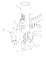
- FIGS. 3a to 3d An optional locking device 100 for the pivoting movement of the second jaw part 32 is in the FIGS. 3a to 3d shown.
- the proximal end of the actuating rod 32b is not directly connected to the pivotable second handle portion 42, but the connection is made by means of a sleeve 105, a collet 106 and a ball head 107.
- the proximal end of the actuating rod 32b is inserted into a distal end of a collet 106 ,
- the collet 106 is disposed in a sleeve 105.
- the proximal end of the collet 106 cooperates with a connecting portion of a ball head 107.
- the ball head 107 is inserted into a corresponding recess on the pivotable second handle part 42.
- the collet 106 axially displaceable in the sleeve 106, the distance between the second handle part 42 and the proximal end of the actuating rod 32b is slightly variable.
- a latching projection 103 is arranged, which cooperates with a latching hook 102 of a blocking element 101.
- the blocking element 101 is preferably designed as a leaf spring and arranged on the shaft tube 20 or a rigidly connected to the shaft tube 20 element.
- the mouth part 42 is pivoted in such a way that the second jaw part 32 is swiveled towards the first jaw part 31 is, the mouth is closed and clamped between the two jaw parts 31, 32 lying tissue in the jaw part.
- the latching hook 102 engages the latching projection 103.
- the mouth part is closed, it is possible to coagulate by applying power to the two coagulation plates 33, 34. After coagulation, an audible or visual signal may be emitted to indicate that the coagulation process has been completed. Subsequently, a cutting operation can take place, which will be described in more detail below.
- the latching between the latching hook 102 and the latching projection 103 must be made to circulate at elevated pressure via the collet 106 and, in particular, the latching hook 102 must be brought out of engagement with the latching projection 103.
- the collet 106 yields in the axial direction until the latching connection between the latching hook 102 and the latching projection 103 is released. The mouth can now be opened again.
- the second grip part 42 is acted upon by a spring element 90, which is arranged, for example, between the second grip part 42 and the distal end 20 a of the shaft tube 20, that the spring element 90, unless an opening of the mouth is prevented by the locking device 100 , Acted automatically by the spring element 90 applied in user-unloaded state.
- a spring element 90 which is arranged, for example, between the second grip part 42 and the distal end 20 a of the shaft tube 20, that the spring element 90, unless an opening of the mouth is prevented by the locking device 100 , Acted automatically by the spring element 90 applied in user-unloaded state.
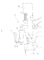
- the coagulation instrument 10 may include a knife 50 having a distal end 50 a and a proximal end 50 b disposed in the working end 30.
- the knife 50 may be pivotally mounted about a pivot axis 58 in the working end 30. So that the knife 50 at a Does not interfere with the coagulation process, the knife 50 can be sunk through a slot 33a in the first coagulation plate 33 in the first jaw part 31 so that it no longer protrudes into the space between the first coagulation plate 33 and the second Koagulationsplatte 34.
- the knife 50 can also be retractable in the movable second jaw part 32. In a cutting operation, the knife 50 is pivoted about the pivot axis 58. So that in particular a cutting is possible even when the jaw part is closed, the second coagulation plate 34 has a slot 34a, into which the knife 50 can penetrate during cutting.
- the knife 50 is interchangeably disposed in the working end 30, in particular such that it can be removed through the jaw member from the distal end of the coagulation instrument 10, in particular without the coagulation instrument 10 having to be completely disassembled or the knife 50 through the shaft tube 20 to the proximal End must be removed.
- the knife is arranged with its proximal end 50b in a blade receptacle 54, which is arranged pivotably about the pivot axis 58.
- the knife 50 can be inserted into the knife holder 54 and locked there, in particular latched.
- the blade receptacle 54 may have a ball head 52, which engages in a bore 56 of the blade 50 latching.
- the blade holder 54 is pivotally connected about the pivot axis 58 with an actuating rod 60, which is guided by the shaft tube 20 and at the proximal end 20 b of the shaft tube 20 by means of a trigger 70 is actuated.
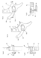
- the trigger 70 is pivotally mounted in particular on a pivot axis 72 on the shaft tube 20 or, as in the FIG. 3a illustrated, arranged on the fixed first handle portion 41.
- the pivotal connection between the trigger 70 and the actuating rod 60 via the pivotal connection 73. If the trigger 70 is pivoted about the pivot axis 72, the actuating rod 60 is moved in the axial direction in the shaft tube 20 forward or back and about the blade 50 is pivoted about the pivot axis 58 to trigger a cutting operation.
- the trigger 70 is not accidentally pivoted, a safety device can be provided which blocks the movement of the trigger 70 about the pivot axis 72.
- the trigger 70 may have a T-shaped groove 74, which is in particular curved.
- a spring 80 is guided displaceably arranged, which is designed in particular as a leaf spring.
- the spring 80 has a first end 80a and a second end 80b, the second end 80b being fixed to a stationary element of the coagulation instrument 10, for example the first grip part 41.
- the second end 80b is displaceable upon movement of the trigger 70 in the groove 74.
- a locking pin 82 is arranged, which is guided through the groove 74 on the outside of the trigger 70.
- a push button 84 may be arranged.
- the T-shaped groove 74 has a latching bore 75, in which the latching bolt 82 engages in the locked position. A displacement of the locking bolt 82 along the groove 74 is not possible, so that the movement of the trigger 70 is blocked about the pivot axis 72. If the locking pin 82 is pressed against the spring force of the leaf spring-like spring 80 in the groove 74, the locking pin 82 comes out of engagement with the locking bore 75 (see FIGS. 2c and 2e ), so that a displacement of the locking bolt 82 along the groove 74 is possible. Thus, the trigger 70 can be pivoted about the pivot axis 72 to trigger a cutting operation with the knife 50.
- the trigger 70 is spring-loaded such that it is transferred in not loaded by a user state by the force of the spring in the starting position, in which the knife 50 is recessed in the first jaw member 31 and the safety device is engaged.
- a tubular arrangement 110 may be arranged in the shaft tube 20 with, for example, four tubes 112 arranged parallel to one another (cf. FIG. 5 ), wherein in each of the tubes 112 exactly one of the elements of the two electrical conductors, the actuating rod 32b for the second jaw part 32 and the actuating rod 60 for the knife 50 is arranged.
Landscapes
- Health & Medical Sciences (AREA)
- Life Sciences & Earth Sciences (AREA)
- Surgery (AREA)
- Engineering & Computer Science (AREA)
- Medical Informatics (AREA)
- Veterinary Medicine (AREA)
- Biomedical Technology (AREA)
- Heart & Thoracic Surgery (AREA)
- Nuclear Medicine, Radiotherapy & Molecular Imaging (AREA)
- Molecular Biology (AREA)
- Animal Behavior & Ethology (AREA)
- General Health & Medical Sciences (AREA)
- Public Health (AREA)
- Ophthalmology & Optometry (AREA)
- Physics & Mathematics (AREA)
- Plasma & Fusion (AREA)
- Otolaryngology (AREA)
- Surgical Instruments (AREA)
- Knives (AREA)
Applications Claiming Priority (1)
| Application Number | Priority Date | Filing Date | Title |
|---|---|---|---|
| DE201220010938 DE202012010938U1 (de) | 2012-11-15 | 2012-11-15 | Bipolares Bajonett HF-Instrument zum Koagulieren und Schneiden mit auswecheselbarem Messer und Sicherheitseinrichtung im Abzug |
Publications (1)
| Publication Number | Publication Date |
|---|---|
| EP2732779A1 true EP2732779A1 (fr) | 2014-05-21 |
Family
ID=49641516
Family Applications (1)
| Application Number | Title | Priority Date | Filing Date |
|---|---|---|---|
| EP13193121.4A Withdrawn EP2732779A1 (fr) | 2012-11-15 | 2013-11-15 | Instrument de coagulation bipolaire |
Country Status (2)
| Country | Link |
|---|---|
| EP (1) | EP2732779A1 (fr) |
| DE (2) | DE202012010938U1 (fr) |
Cited By (2)
| Publication number | Priority date | Publication date | Assignee | Title |
|---|---|---|---|---|
| EP3815642A1 (fr) | 2019-10-28 | 2021-05-05 | Erbe Elektromedizin GmbH | Cartouche de lame et instrument pour sceller |
| EP3849441A4 (fr) * | 2018-09-14 | 2022-06-29 | Covidien LP | Déploiement de lame d'articulation |
Citations (5)
| Publication number | Priority date | Publication date | Assignee | Title |
|---|---|---|---|---|
| DE19637133A1 (de) * | 1995-09-12 | 1997-03-13 | Cabot Tech Corp | Behältnis für Messeraufbau und Verfahren |
| US5913874A (en) * | 1997-09-25 | 1999-06-22 | Cabot Technology Corporation | Cartridge for a surgical instrument |
| EP2316366A2 (fr) * | 2009-10-30 | 2011-05-04 | Tyco Healthcare Group, LP | Articulation à rouleaux pour un instrument chirurgical |
| US20120101488A1 (en) * | 2010-10-26 | 2012-04-26 | Ethicon Endo-Surgery, Inc. | Surgical instrument with magnetic clamping force |
| EP2489319A1 (fr) * | 2011-02-18 | 2012-08-22 | Tyco Healthcare Group, LP | Appareil de découpe sélective de plusieurs canaux |
-
2012
- 2012-11-15 DE DE201220010938 patent/DE202012010938U1/de not_active Expired - Lifetime
-
2013
- 2013-11-15 DE DE201320012036 patent/DE202013012036U1/de not_active Expired - Lifetime
- 2013-11-15 EP EP13193121.4A patent/EP2732779A1/fr not_active Withdrawn
Patent Citations (5)
| Publication number | Priority date | Publication date | Assignee | Title |
|---|---|---|---|---|
| DE19637133A1 (de) * | 1995-09-12 | 1997-03-13 | Cabot Tech Corp | Behältnis für Messeraufbau und Verfahren |
| US5913874A (en) * | 1997-09-25 | 1999-06-22 | Cabot Technology Corporation | Cartridge for a surgical instrument |
| EP2316366A2 (fr) * | 2009-10-30 | 2011-05-04 | Tyco Healthcare Group, LP | Articulation à rouleaux pour un instrument chirurgical |
| US20120101488A1 (en) * | 2010-10-26 | 2012-04-26 | Ethicon Endo-Surgery, Inc. | Surgical instrument with magnetic clamping force |
| EP2489319A1 (fr) * | 2011-02-18 | 2012-08-22 | Tyco Healthcare Group, LP | Appareil de découpe sélective de plusieurs canaux |
Cited By (3)
| Publication number | Priority date | Publication date | Assignee | Title |
|---|---|---|---|---|
| EP3849441A4 (fr) * | 2018-09-14 | 2022-06-29 | Covidien LP | Déploiement de lame d'articulation |
| EP3815642A1 (fr) | 2019-10-28 | 2021-05-05 | Erbe Elektromedizin GmbH | Cartouche de lame et instrument pour sceller |
| US12048454B2 (en) | 2019-10-28 | 2024-07-30 | Erbe Elektromedizin Gmbh | Knife cartridge and sealing instrument |
Also Published As
| Publication number | Publication date |
|---|---|
| DE202013012036U1 (de) | 2015-03-18 |
| DE202012010938U1 (de) | 2014-02-18 |
Similar Documents
| Publication | Publication Date | Title |
|---|---|---|
| DE102008052178B4 (de) | Klemminstrument für ein endoskopisches Operationsgerät | |
| EP0692224B1 (fr) | Instrument médical à fonctions multiples utilisé pour des opérations endoscopiques | |
| EP1082061B1 (fr) | Poignee pour un instrument medical a tige creuse | |
| DE3533645C2 (fr) | ||
| EP1809444B1 (fr) | Dispositif servant a verrouiller un bloc-batterie dans une coulisse d'un outil electrique | |
| EP0634139B1 (fr) | Instrument médical démontable | |
| DE2858032C2 (de) | Chirurgisches Klammerinstrument zum Klammern von Hohlorganen | |
| DE69602968T2 (de) | VERBINDUNGSVORRICHTUNG UND HIERMIT AUSGERüSTETES WERKZEUG ZUM ERZEUGEN EINES DREHANTRIEBS | |
| EP4117866B1 (fr) | Dispositif de préhension pour outil électrique portatif | |
| DE2109319B2 (de) | Werkzeug zum Lösen von Kontaktstiften und Kontaktbuchsen aus den Kontaktkammern von Isolierkörpern von Steckverbindern | |
| EP2732779A1 (fr) | Instrument de coagulation bipolaire | |
| EP2476381A1 (fr) | Instrument chirurgical décomposable doté d'une tête plate | |
| EP1319456A1 (fr) | Découpeur de câbles | |
| DE10125149B4 (de) | Medizinische Zange | |
| DE19624811A1 (de) | Saug- und Spülinstrument | |
| WO2004075765A1 (fr) | Instrument chirurgical | |
| EP2904977B1 (fr) | Instrument chirurgical et poignée pour celui-ci | |
| EP3815642B1 (fr) | Cartouche de lame et instrument pour sceller | |
| DE102011014200B4 (de) | Stechhilfe mit seitlich angebrachtem Betätigungselement | |
| DE202013100819U1 (de) | Skalpellhalter | |
| DE10156917A1 (de) | Instrument für die endoskopische Chirurgie | |
| EP3471219B1 (fr) | Système de fiche et connecteur destiné à la fabrication d'un connecteur enfichable électrique | |
| EP4079240B1 (fr) | Cartouche à lames pour un instrument chirurgical | |
| EP3049143B1 (fr) | Dispositif de pose pour un cathéter médical | |
| EP3179931B1 (fr) | Instrument medical pour la chirurgie endoscopique |
Legal Events
| Date | Code | Title | Description |
|---|---|---|---|
| PUAI | Public reference made under article 153(3) epc to a published international application that has entered the european phase |
Free format text: ORIGINAL CODE: 0009012 |
|
| 17P | Request for examination filed |
Effective date: 20131115 |
|
| AK | Designated contracting states |
Kind code of ref document: A1 Designated state(s): AL AT BE BG CH CY CZ DE DK EE ES FI FR GB GR HR HU IE IS IT LI LT LU LV MC MK MT NL NO PL PT RO RS SE SI SK SM TR |
|
| AX | Request for extension of the european patent |
Extension state: BA ME |
|
| STAA | Information on the status of an ep patent application or granted ep patent |
Free format text: STATUS: THE APPLICATION IS DEEMED TO BE WITHDRAWN |
|
| 18D | Application deemed to be withdrawn |
Effective date: 20141122 |