EP2735317A1 - Sterile liquid transfer port - Google Patents
Sterile liquid transfer port Download PDFInfo
- Publication number
- EP2735317A1 EP2735317A1 EP20140155832 EP14155832A EP2735317A1 EP 2735317 A1 EP2735317 A1 EP 2735317A1 EP 20140155832 EP20140155832 EP 20140155832 EP 14155832 A EP14155832 A EP 14155832A EP 2735317 A1 EP2735317 A1 EP 2735317A1
- Authority
- EP
- European Patent Office
- Prior art keywords
- assembly
- beta
- product
- alpha
- cover
- Prior art date
- Legal status (The legal status is an assumption and is not a legal conclusion. Google has not performed a legal analysis and makes no representation as to the accuracy of the status listed.)
- Granted
Links
Images





Classifications
-
- A—HUMAN NECESSITIES
- A61—MEDICAL OR VETERINARY SCIENCE; HYGIENE
- A61L—METHODS OR APPARATUS FOR STERILISING MATERIALS OR OBJECTS IN GENERAL; DISINFECTION, STERILISATION OR DEODORISATION OF AIR; CHEMICAL ASPECTS OF BANDAGES, DRESSINGS, ABSORBENT PADS OR SURGICAL ARTICLES; MATERIALS FOR BANDAGES, DRESSINGS, ABSORBENT PADS OR SURGICAL ARTICLES
- A61L2/00—Disinfection or sterilisation of materials or objects, in general; Accessories therefor
- A61L2/26—Accessories
-
- A—HUMAN NECESSITIES
- A61—MEDICAL OR VETERINARY SCIENCE; HYGIENE
- A61L—METHODS OR APPARATUS FOR STERILISING MATERIALS OR OBJECTS IN GENERAL; DISINFECTION, STERILISATION OR DEODORISATION OF AIR; CHEMICAL ASPECTS OF BANDAGES, DRESSINGS, ABSORBENT PADS OR SURGICAL ARTICLES; MATERIALS FOR BANDAGES, DRESSINGS, ABSORBENT PADS OR SURGICAL ARTICLES
- A61L2/00—Disinfection or sterilisation of materials or objects, in general; Accessories therefor
- A61L2/02—Disinfection or sterilisation of materials or objects, in general; Accessories therefor using physical processes
- A61L2/04—Heat
- A61L2/06—Hot gas
- A61L2/07—Steam
-
- Y—GENERAL TAGGING OF NEW TECHNOLOGICAL DEVELOPMENTS; GENERAL TAGGING OF CROSS-SECTIONAL TECHNOLOGIES SPANNING OVER SEVERAL SECTIONS OF THE IPC; TECHNICAL SUBJECTS COVERED BY FORMER USPC CROSS-REFERENCE ART COLLECTIONS [XRACs] AND DIGESTS
- Y10—TECHNICAL SUBJECTS COVERED BY FORMER USPC
- Y10T—TECHNICAL SUBJECTS COVERED BY FORMER US CLASSIFICATION
- Y10T137/00—Fluid handling
- Y10T137/8593—Systems
Definitions
- a transfer port apparatus and method enables the uncontaminated transfer of a sterile liquid from a relatively dirty environment to a relatively clean environment through a transfer port in an isolation wall that separates the dirty environment from the clean environment.
- a bulk quantity of sterile liquid product must be transferred to smaller containers for distribution to end users.
- the transfer process begins by filling a product tank with product.
- the sterile liquid product is then conveyed from inside the product tank, through the inside of a product hose, and through the inside of a product tube.
- the product tube is a part of a transfer port apparatus.
- the sterile liquid is conveyed from the product tube into a filling hose and then into filling equipment, which sequentially fills a number of smaller containers.
- the interiors of the product tank, product hose, and product tube may be contaminated by biological agents and nonviable particles, such as dust. Both the biological agents and the nonviable particles will compromise the sterility of the sterile liquid product unless they are removed prior to filling the product tank and associated conduits.
- the sterile liquid transfer port rids the contamination by steam cleaning the product tank and associated conduits by use of a beta assembly and a sterilization docking cover.
- the relatively dirty environment can contaminate the cleaner environment with nonviable particles.
- a physical barrier between the dirty environment, in which the product tank is located, and the clean environment is interposed.
- the barrier is comprised of the alpha assembly of the sterile liquid transfer port in conjunction with the beta assembly.
- the sterile liquid transfer port provides for safe, fast, economical, and cost effective (i) sterilization of the product container and conduits through which the sterile liquid product is transferred and (ii) isolation of the less clean environment from the clean environment.
- Transfer of liquid product from a sterilized interior of the product tank 202 (located in the product suite 205) to the filling equipment 209 (located in the filling suite 204) is a fairly simple task once sterilization is complete. Transfer of the sterile liquid product is through a transfer port 201 b in an isolation wall 201.
- the alpha assembly of the SLTP also isolates the product suite 205, the less clean environment, from the filling suite 204, the clean environment.
- the product suite 205 houses a product tank 202 for containment of a bulk quantity of a sterile liquid product.
- the filling suite 204 houses filling equipment 209 for commercial packaging of smaller amounts of product.
- the product suite 205 has a lower level of cleanliness (for example, a Class 10,000 environment) than the filling suite 204 (for example, a Class 100 environment).
- the pharmaceutical setting gives rise to a requirement for moving a biological agent from the product suite 205 to the filling suite 204, where relatively small quantities of product are transferred into containers for distribution, such as aseptic vials and syringes.
- the SLTP is comprised of an alpha assembly, a beta assembly, and a sterilization docking cover.
- the transfer port apparatus can also be comprised of (a) an isolation wall; (b) a product suite on a first side of the isolation wall; (c) a filling suite on a second side of the isolation wall; (d) an alpha assembly spanning a port in the isolation wall between the first and second sides of the isolation wall; (e) a product tank; (f) a means for sterilization of the product tank, a conduit, and a beta assembly; (g) the beta assembly configured for connection with the alpha assembly for sterile transfer of a product; (h) a conduit for transferring product from the product suite to the filling suite; and (i) equipment in the filling suite for filling product.
- the transfer port apparatus implements a method of transferring a sterile liquid from a product suite to a filling suite by (a) sterilization of the means for transferring the sterile liquid to a product tube on a beta assembly; (b) insertion of an alpha assembly through a port in an isolation wall; (c) mating a beta assembly with the alpha assembly; (d) opening an alpha door into the filling suite; (f) connecting a means for transferring the sterile liquid from the product suite to the filling suite; and (g) transferring the sterile liquid from the product suite to the filling suite.
- the SLTP isolates the clean environment and provides uncontaminated transfer of the sterile liquid product. Isolation of the clean environment is accomplished by a single step sterilization process. Uncontaminated transfer of the sterile liquid product is accomplished by the combination of the alpha assembly and the beta assembly.
- the SLTP includes two main components - the alpha assembly 10 and the beta assembly 100.
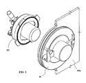
- Figure 1 is an isometric view of the alpha and beta assemblies 10 and 100 of the sterile liquid transfer port, and can be understood in the context of Figures 5I and 5J.
- Figure 5I is an elevation view of the SLTP in the filling mode
- Figure 5J is a detailed view of the SLTP in the filling mode.
- Figure 5I depicts an SLTP system in a relevant environment, where an isolation wall 201 separates a first side 205 from a second side 204.
- the first side 205 can be a product suite having a product tank 202.
- the second side 204 can be a filling suite having filling equipment 209.
- the first side 205 can be a relatively "dirty” side, and can be classified as a Class 10,000 environment.
- the second side 204 can be a relatively "clean" side, which can be classified as a Class 100 environment.
- An SLTP system can aid in such liquid transfer.
- the alpha assembly 10 spans a transfer port 201b in an isolation window 201a. While the alpha assembly 10 can be primarily associated with the filling suite 204 (a Class 100 environment), as depicted in Figure 5I , the alpha assembly 10 extends into the product suite 205, which is the relatively "dirty" environment such that its rear portion is exposed to the Class 10,000 environment.
- the beta assembly 100 however is exclusively associated with the product suite 205, or the "dirty" side, in various embodiments, and docks to that rear portion of the alpha assembly 10.
- the alpha assembly 10 is configured to dock with the beta assembly 100, which is demonstrated progressively from Figure 5A to Figure 5F , and is described below.
- product can be transferred from the product suite 205 to the filling suite 204 ( Figure 5I ) without breaking containment.
- the beta assembly 100 is mounted in-line with the alpha assembly 10, as depicted in Figure 5A .
- a rigid product tube 109 extends into the filling suite 204 and is ready for attachment to a sterile flexible filling hose 208.
- the sterile flexible filling hose 208 can deliver product (for example serum and vaccines) to commercially-sized containers for distribution.
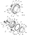
- FIG 2A is an exploded view of the alpha assembly 10.
- the alpha assembly 10 has a first flange gasket 18, second flange gasket 18, a flange nut 17, an alpha flange 11 and an alpha door 16.
- the flange gasket 18 is a seal between the alpha flange 11 and the isolation window 201a. The seal prevents leakage from a first side of the isolation window 201a to a second side of the isolation window 201 a, or the second side of the isolation window 201a to the first side of the isolation window 201a.
- a second flange gasket 18 is located on the opposite side of the isolation window 201a than that of the first flange gasket 18.
- the second flange gasket 18 also serves the purpose of preventing leakage from the product suite 205 side of the isolation window 201a into the filling suite 204 side of the isolation window 201a (depicted in Figure 5I ).
- the alpha door 16 is disposed on the alpha flange 11.
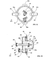
- FIG 2B is an elevation view of the alpha assembly 10.
- the alpha assembly 10 comprises an alpha flange 11 and an alpha door 16.
- the alpha door 16 opens into one side of the isolation wall, which can be the filling suite side of the isolation wall depicted in Figure 5I .
- the alpha door 16 is generally closed, unless a filling operation is in progress.
- the alpha door 16 also remains closed during sterilization, which can include sterilization of the product tank 202, such as the one depicted in Figure 5I . Sterilization generally takes place prior to initiation of a filling operation.
- Figure 2B also illustrates a latch 13 affixed to alpha door 16.
- a latch handle 14 engages with latch 13. When the latch handle 14 is in the up position, latch 13 is locked, as is the alpha door 16, in one example embodiment.
- the alpha door 16 is in a locked position whenever it is closed to avoid inadvertent contamination of clean side of the isolation wall, which can be the filling suite 204 from Figure 5I , in one embodiment.
- a mechanical latch interlock 15 can prevent improper or unwanted operation of the SLTP.
- improper operations could include: opening the alpha door 16 before the beta assembly 100 is docked with the alpha assembly 10; removing the beta assembly 100 from the alpha assembly 10 when the alpha door 16 is open; and rotating the latch handle 14 of the alpha door 16 when the alpha door 16 is open.
- Latch interlock 15 can prevent accidental opening of alpha door 16.
- the alpha door 16 can be opened when the beta assembly 100 is docked with the alpha assembly 10 due to automatic disengagement of the latch interlock 15 by the beta assembly 100.
- the alpha door 16 can then be safely opened by rotation of the latch handle 14, counter-clockwise 180°, in one embodiment, although other angles of rotation could be foreseen.
- FIG. 2B also illustrates a hinge assembly 12 comprised of a hinge 12a, a hinge pivot block 12b, and a hinge pin 12c.
- the hinge 12a is affixed to alpha door 16.
- the hinge assembly 12 provides a pivot connection between the alpha door 16 and the alpha flange 11 in a plane.
- Hinge 12a allows pivoting or rotation of the alpha door 16 around the hinge pin 12c to both open and close the alpha door 16.
- the hinge pivot block 12b acts as a support guide to maintain the alpha door 16 in horizontal alignment during rotation or pivoting and during the time it is in the open position.
- Figure 2C is a cross-sectional view of the alpha assembly 10 of Figure 2B .
- the alpha assembly 10 is intended to maintain isolation of a first side of an isolation wall from a second side of an isolation wall, such as the product suite 205 from the filling suite 204 as depicted in Figure 5I . Such isolation is maintained regardless of whether the SLTP is in a sterilization mode or a filling mode.
- the installation of the alpha flange 11 is relatively permanent, while the beta flange 101 is often inserted and removed. Now an example structure of the alpha assembly 10 will be described.
- the alpha assembly 10 is comprised of a flange 11, alpha door 16, bayonet receiver 11a, bayonet receiver channel 11b, flange nut 17, alpha seal 19, gasket 18 on the product suite side, and gasket 18 on the filling suite side.
- the alpha seal 19 surrounds the inside of the alpha door 16 and seals the door 16 to the flange 11 upon closure.
- an isolation window 201a is installed in an opening in the isolation wall 201 and the alpha flange 11a is installed in the transfer port 201b in the isolation wall 201.
- the alpha flange 11 is inserted into a transfer port 201b (see Figure 2A ) in an isolation wall 201.
- gasket 18 on the filling suite side is put in place around the flange 11.
- the isolation window 201a is used to monitor activity in the product and/or filling suites 204 and 205.
- gasket 18 on the product suite 204 side is placed around the flange 11 and flange nut 17 is tightened down against the isolation window 201a or the isolation wall 201, as the case may be.
- FIG 2D is an elevational view of the alpha assembly 10 viewed from the rear.
- Alpha bayonet receiver 11a can also be referred to as a third connector set 11a, and is configured for mating engagement with a beta flange bayonet 101a when a beta assembly 100 is docked with the alpha assembly 10.
- the beta flange bayonet 101a can be referred to as a first connector set.
- handles 104a are used to rotate the beta flange bayonets 101a counter-clockwise to releasably lock the beta flange bayonets 101a under the alpha bayonet receiver channel 11b.
- Alpha door bayonets 16a which can be referred to as a fourth connector set 16a, are also configured for mating engagement with beta cover bayonet receivers 102b, where the beta cover bayonet receivers 102b can be referred to as a second connector set 102b.
- Handles 104a are used to further rotate the docked beta assembly 100 counter-clockwise to rotation of the beta flange releasably lock the alpha door bayonets 16a under the beta cover bayonet receiver channels 102c.
- Figure 2E is an isometric view of the alpha assembly 10 with the alpha door 16 closed. As previously mentioned, latch handle 14 is engaged with latch 13. When latch handle 14 is in the up position it locks latch 13 and thereby alpha door 16.
- Figure 2F is an isometric view of the alpha assembly with the alpha door open. To open the alpha door 16, latch handle 14 is rotated counter-clockwise 180°.
- FIG 3A is an isometric view of a beta assembly 100 from the front.
- the beta assembly is configured for connection with the alpha assembly from the first side of the isolation wall for sterile transfer of a product.
- the beta assembly generally has a housing having a first side 101 and second side 102 that define an interior space, where the first side 101 can be a beta flange 101 and the second side 102 can be a beta cover 102.
- a first connector set 101a is defined on the first side 101 and a second connector set 102b is defined on the second side 102.
- the beta flange 101 can be releasably locked to the beta cover 102.
- flange bayonets 101a on the first side 101 of the housing are configured to engage bayonet receivers 111b of the docking cover.
- the beta assembly 100 also has a beta seal 103.
- the beta cover 102 includes a beta cover end cap 102d that provides a closed interior space 100a for the rigid product tube 109 and a rigid drain tube 107 (shown in Figure 3B ).
- the product tube 109 defines a passage from the interior space 100a to outside of the housing.
- the closed interior space 100a created by the cover end cap 102d is used in the sterilization mode.
- Sanitary fitting clamp 110 connects a flexible product hose 203 to a rigid product tube 109 for use during the sterilization process and for transfer of product during the filling process.
- the beta cover 102 is releasably locked to the beta flange by alignment of the beta cover bayonets 102a with the bayonet cover receivers 101b of the beta flange 100, followed by rotation of the beta cover bayonets 102a under the beta cover bayonet receiver channels 101c.
- Beta flange 101 comprises at least one handle, in some embodiments two handles, and brackets 104a and 104b, sanitary fitting clamp 110, and flange bayonets 101a.
- a first connector set 101a which can be flange bayonets 101a, are aligned with the alpha bayonet receiver 11a during docking of the beta assembly 100 with the alpha assembly 10.
- Cover seal 103 seals the beta cover end cap 102 to the beta flange 101 when the beta cover 102 is connected to beta flange 101.
- Handles 104a are used to rotate the beta flange bayonets 101a counter-clockwise to releasably lock the beta flange bayonets 101a under the alpha bayonet receiver channels 11b.
- Alpha door bayonets 16a are configured for mating engagement with beta cover bayonet receivers 102b. Rotation of the beta flange bayonets 101a counter-clockwise also releasably locks the alpha door bayonets 16a under the beta flange bayonet receiver channels 102c.
- Figure 3B is an exploded, isometric view of the beta assembly 100 from the front. In this view, the interior space 100a of the beta flange can be clearly seen.
- a first hose connection device incorporating a combination of the sanitary fitting clamp 110, the sanitary fitting cap 106, and the sanitary fitting seal 105 provides the connection between a flexible product hose 203 from the product tank 202 and the rigid product tube 109 without the use of tools.
- a second hose connection device incorporates a combination of the sanitary fitting clamp 110, sanitary fitting seal 105, and sanitary fitting cap 106, to provide a connection between a product tube 109 and a flexible filling hose 208 without the use of tools.
- a rigid drain tube 107 is shown in the interior space 100a and is combined with the sanitary fitting clamp 110, sanitary fitting seal 105, and sanitary fitting adaptor 108. It provides the connection between the interior space 100a of the beta assembly 100, the rigid drain tube 107, and the flexible steam drain hose 207.
- the rigid drain tube 107 is used during the sterilization process.
- the rigid drain tube 107 defines a passage from the interior space 100a to outside of the housing of the beta assembly 100.
- Figure 3C is an elevational view of the beta assembly from the rear.
- Figure 3D is a cross-sectional view of the beta assembly 100 of Figure 3A .
- the product port and the drain port are capped with sanitary fitting adaptors 106 for storage of the beta assembly.
- a docking cover is generally located on a first side of an isolation wall and is configured for connection with a beta assembly during a sterilization process.
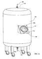
- Figure 4A is an isometric view of the product tank 202 with the docking cover 111 located on the product tank.
- the docking cover 111 may be located on a wall, bench, or other convenient place within the product suite 205.
- the tank 202 is shown with wheels to indicate that the tank 202 is movable within the product suite 205 or movable to an entirely different product suit.
- the SLTP will include multiple product tanks 202 and beta assemblies 100, yet only one alpha assembly 10.
- the beta assemblies 100 can also be located in a mobile product suite 205.
- the flexible product hose 203 is used as steam supply hose during sterilization and for transferring product to the beta assembly during filling.
- Each hose 203, 207, and 208 attaches to a sanitary fitting adaptor 108 when connected to the beta assembly 100.
- FIG 4B is an isometric view of the beta assembly 100 aligned for docking with the docking cover 111.
- the docking cover 111 generally defines an opening to accommodate a portion of the housing 100.
- the docking cover 111 is attached to a mounting plate 200 that in turn is attached to the outside of the product tank 202.
- the beta assembly 100, beta cover 102, and the mounting plate 200 are not connected in any way to the inside of the tank 202.
- the docking cover 111 has bayonet receivers 111b, which can be referred to as a fifth connector set 111b, for engagement with the first connector set 101 a, or beta flange bayonets 101a, on the beta assembly 100.
- the first connector set 101 a and fifth connector set 111b can be a variety of mateable components that mate in a variety of different ways even though the connector sets described in the implementations disclosed herein are generally bayonet connections.
- the beta assembly 100 mounts to the docking cover without using any tools.
- the beta cover end cap 102d is inserted into the docking cover opening 111a, which is in alignment with the mounting plate opening 200a.
- the beta assembly After insertion of the bayonets 101a into the bayonet receivers 111b, the beta assembly, as shown in Figure 4D , is mounted to the docking cover by rotating the beta assembly counter-clockwise, using handle assemblies 104, thereby rotating the beta flange bayonets 101a in the docking cover bayonet receiver channels 111c. Sanitary fitting adaptors 108 are also shown.
- Figure 4E is an isometric view of the beta assembly with a flexible product hose 203 and a steam drain hose 207.
- the product hose 203 is connected to the product tube 109 of the beta assembly 100.
- the drain hose 207 is connected to the drain tube 107.
- FIGs 4F and 4G are isometric views of the product tank 202 and the beta assembly 100 docked with the docking cover 111 in the steam sterilization mode.
- Steam from a steam source is introduced into the top of the product tank 202 and passes through the flexible steam supply hose 206. Steam exits at the bottom of the tank 202 through the flexible product hose 203 and into the beta assembly 100 via rigid product tube 109. Steam continues its travel through the interior 100a of the beta assembly 100, out the rigid drain tube 107, through the flexible steam drain hose 207, and into a condensate tank for disposal (not depicted).
- FIG. 4G illustrates the detail of the beta assembly interior 100a and the hose connections to the beta assembly 100.
- a seal 103 positioned between a portion of the beta cover and a portion of the beta flange, wherein the docking cover contacts the seal when the beta assembly is mated to the docking cover.
- the docking cover supports the seal during the sterilization process.
- the combination of the beta cover, beta flange and docking cover contact the seal on all sides of the seal. Without the cover, steam pressure during the sterilization process could cause the seal to be forced out of its seat, thereby possibly causing a leak which would be a failure of the sterilization process.
- the seal 103 With the docking cover, the seal 103 is further supported and a successful sterilization process is more likely.
- the beta assembly 100 is an integral part of the sterilization process.
- the sterilization system comprises the interior surfaces of the empty (i) product tank 202, (ii) flexible product hose 203, (iii) flexible steam supply hose 206, (iv) flexible steam drain hose 207, (v) beta assembly 100, and (vi) steam source.
- the beta assembly 100 comprises the beta assembly interior 100a.
- the interior 100a comprises the (i) rigid product tube 109, (ii) beta flange 101, (iii) beta cover 102, and (iv) outlet 107a of the rigid drain tube.
- Exposure to elevated temperature and pressure for an extended period ensures sterilization of all of the internal surfaces of the sterilization system.
- the alpha door 16 of the alpha assembly 10 is closed and sealed while sterilization takes place.
- Saturated steam at the elevated temperature and pressure is circulated through the sterilization system.
- the saturated steam is injected through the system at a working pressure of about 36.3 psi (depending upon the product type).
- the saturated steam temperature is about 150° Centigrade (depending upon the product type) when it enters the system.
- the required level of sterilization is maintained by continually monitoring the steam temperature at the rigid drain tube 107 to ensure that the steam temperature at the drain tube 107 remains at or about 150° Centigrade (depending upon the product type).
- condensate is removed from the system by injecting hot, dry air through the system.
- the beta assembly 100 Upon completion of the sterilization process the beta assembly 100 is undocked from the docking cover 111 and docked with the alpha assembly 10.
- the flexible product hose 203 was connected at the rear of the beta assembly 100 to the rigid product tube 109.
- the flexible product hose 203 must remain connected.
- the flexible steam drain hose 207 and the sanitary fitting adaptor 108 must be removed from the rigid drain tube 107 and replaced with the sanitary fitting cap 106.
- Figure 5A is an isometric view of the beta and alpha assemblies 100 and 10 with the beta assembly aligned for docking with the alpha assembly.
- a first connector set 101a on the first side 100 and a second connector set 102b on the second side 102 visible in Figure 3A , for example), where the first connector set 101a is configured to be mated with a third connector 111a set on the alpha assembly 10 and the second connector set 102b is configured to be mated with a fourth connector set 16a on the alpha assembly 10.
- the first connector set 101a can also be configured to be mated with a fifth connector set on a product tank as described above in the discussion of Figure 4B-4E .
- FIG. 5B is an isometric view of the beta assembly with the beta flange bayonets 101a received in the alpha bayonet receivers 11a.
- Those skilled in the art will appreciate that a variety of other types of connections can be employed and still remain in the scope of the technology disclosed herein.
- the beta flange bayonets 101a are then rotated counter-clockwise under the alpha bayonet receiver channels 11b.
- the first 101a and third 111b connector sets can be configured to engage and disengage upon rotation with respect to each other.
- the second and fourth connector sets can be configured to engage and disengage upon rotation with respect to each other, although other means of engaging and disengaging the first and third connector sets can be employed.
- Figure 5D is an isometric view of the alpha and beta assemblies 10 and 100 with the alpha door 16 latched.
- Figure 5E is an isometric view of the alpha and beta assemblies 10 and 100 with the alpha door 16 unlatched.
- Figure 5F is an isometric view of the alpha and beta assemblies with the alpha door 16 open, thereby allowing access to the sanitary fitting adaptor 108 for attachment to the flexible filling hose 208.
- Figure 5G is an isometric view of alpha and beta assemblies 10 and 100 having one rigid product tube 109.
- Figure 5H is an isometric view of the alpha and beta assemblies 10 and 100 having two rigid product tubes 109.
- two substances may be differentially metered from separate product tanks into the respective product tubes 109 for combination into a two-part medicant. In this manner any number of individual product tubes may be employed to mix the various substances together.
- the rear of the beta cover 102 is captured by the alpha door 16 when the beta assembly 100 is engaged with the alpha assembly 10.
- the flexible filling hose 208 extends into the filling suite 204.
- Figure 5I is an elevation view of the SLTP in the filling mode.
- Figure 5J is a detailed view of the SLTP in the filling mode. Transfer of product to the filling suite 204 may be accomplished by pumping, gravity feed, or pressurization of the product tank 202. Typically, product is stored under pressure.
- the alpha assembly 10 and the beta assembly 100 implement the process of uncontaminated transfer of sterile liquid product.
- the product suite 205 is always isolated from the filling suite 204 by an alpha assembly 10.
- the alpha assembly 10 has an interface for docking the beta assembly 100.
- the alpha assembly 10 is configured so the alpha door 16 cannot be opened without the beta assembly 100 docked to the alpha assembly 10. This ensures that the product suite 205 will not contaminate the filling suite 204.
- the flexible steam supply hose 206 is shut-off from the product tank 202
- the flexible steam drain hose 207 is shut-off from the sanitary fitting adaptor 108 on the beta assembly 100, the adaptor is removed from the beta assembly, and the adaptor 108 is replaced with a plug
- the beta assembly 100, with its attached flexible product hose 203 is undocked from the docking cover 111 and docked with the alpha assembly 10.
- the product tank 202 is filled with product.
- Rotating the beta assembly 100 and docking it to the alpha assembly 10 causes four events to simultaneously occur.
- Second, docking causes the beta cover 102 to become detached from the beta flange.
- the docking process disengages the interlock mechanism on the alpha assembly 10 thus enabling the alpha door 16 to be safely opened.
- the beta cover 102 becomes separated from the beta flange 101 thereby exposing the sterile rigid product tube 109, sterile sanitary fitting seal 105, sterile sanitary fitting adaptor 108, and sterile sanitary fitting clamp 110 to the clean filling suite 204.
- Attachment of a flexible filling hose 208 enables transfer of the sterile liquid without contamination from the product suite 205 into the filling suite 204 and subsequently into the filling equipment 209.
- aspects of the invention may include any of the following.
Landscapes
- Health & Medical Sciences (AREA)
- Epidemiology (AREA)
- Life Sciences & Earth Sciences (AREA)
- Animal Behavior & Ethology (AREA)
- General Health & Medical Sciences (AREA)
- Public Health (AREA)
- Veterinary Medicine (AREA)
- Apparatus For Disinfection Or Sterilisation (AREA)
- Quick-Acting Or Multi-Walled Pipe Joints (AREA)
Abstract
Description
- This application is being filed as a PCT International Patent application on October 5, 2009, in the name of Delaware Capital Formation Inc., a U.S. national corporation, applicant for the designation of all countries except the U.S., and Richard H. Adams, a U.S. Citizen, Miles A. Close, a U.S. Citizen, and Amos E. Avery, a U.S. Citizen, applicants for the designation of the U.S. only, and claims priority to
U.S. Patent Application Serial Number 12/245,603, filed October 3, 2008 - A transfer port apparatus and method enables the uncontaminated transfer of a sterile liquid from a relatively dirty environment to a relatively clean environment through a transfer port in an isolation wall that separates the dirty environment from the clean environment.
- A bulk quantity of sterile liquid product must be transferred to smaller containers for distribution to end users. The transfer process begins by filling a product tank with product. The sterile liquid product is then conveyed from inside the product tank, through the inside of a product hose, and through the inside of a product tube. The product tube is a part of a transfer port apparatus. The sterile liquid is conveyed from the product tube into a filling hose and then into filling equipment, which sequentially fills a number of smaller containers.
- Prior to being filled with the sterile liquid product, the interiors of the product tank, product hose, and product tube may be contaminated by biological agents and nonviable particles, such as dust. Both the biological agents and the nonviable particles will compromise the sterility of the sterile liquid product unless they are removed prior to filling the product tank and associated conduits. The sterile liquid transfer port rids the contamination by steam cleaning the product tank and associated conduits by use of a beta assembly and a sterilization docking cover.
- Furthermore, the relatively dirty environment can contaminate the cleaner environment with nonviable particles. To avoid contamination of the cleaner environment, in which filling of the smaller containers takes place, a physical barrier between the dirty environment, in which the product tank is located, and the clean environment is interposed. The barrier is comprised of the alpha assembly of the sterile liquid transfer port in conjunction with the beta assembly.
- Accordingly, the sterile liquid transfer port ("SLTP") provides for safe, fast, economical, and cost effective (i) sterilization of the product container and conduits through which the sterile liquid product is transferred and (ii) isolation of the less clean environment from the clean environment.
- Transfer of liquid product from a sterilized interior of the product tank 202 (located in the product suite 205) to the filling equipment 209 (located in the filling suite 204) is a fairly simple task once sterilization is complete. Transfer of the sterile liquid product is through a
transfer port 201 b in anisolation wall 201. - The alpha assembly of the SLTP also isolates the
product suite 205, the less clean environment, from thefilling suite 204, the clean environment. Theproduct suite 205 houses aproduct tank 202 for containment of a bulk quantity of a sterile liquid product. Thefilling suite 204 houses fillingequipment 209 for commercial packaging of smaller amounts of product. Typically, theproduct suite 205 has a lower level of cleanliness (for example, a Class 10,000 environment) than the filling suite 204 (for example, aClass 100 environment). - An example of the use of the SLTP is a pharmaceutical setting. The pharmaceutical setting gives rise to a requirement for moving a biological agent from the
product suite 205 to thefilling suite 204, where relatively small quantities of product are transferred into containers for distribution, such as aseptic vials and syringes. - In one embodiment, the SLTP is comprised of an alpha assembly, a beta assembly, and a sterilization docking cover. The transfer port apparatus can also be comprised of (a) an isolation wall; (b) a product suite on a first side of the isolation wall; (c) a filling suite on a second side of the isolation wall; (d) an alpha assembly spanning a port in the isolation wall between the first and second sides of the isolation wall; (e) a product tank; (f) a means for sterilization of the product tank, a conduit, and a beta assembly; (g) the beta assembly configured for connection with the alpha assembly for sterile transfer of a product; (h) a conduit for transferring product from the product suite to the filling suite; and (i) equipment in the filling suite for filling product.
- In one embodiment, the transfer port apparatus implements a method of transferring a sterile liquid from a product suite to a filling suite by (a) sterilization of the means for transferring the sterile liquid to a product tube on a beta assembly; (b) insertion of an alpha assembly through a port in an isolation wall; (c) mating a beta assembly with the alpha assembly; (d) opening an alpha door into the filling suite; (f) connecting a means for transferring the sterile liquid from the product suite to the filling suite; and (g) transferring the sterile liquid from the product suite to the filling suite.
- The following drawings present embodiments of the SLTP.
-
Figure 1 is an isometric view of the alpha and beta assemblies of the sterile liquid transfer port. -
Figure 2A is an exploded view of the alpha assembly. -
Figure 2B is an elevation view of the alpha assembly. -
Figure 2C is a cross-sectional view of the alpha assembly ofFigure 2B . -
Figure 2D is an elevational view of the alpha assembly viewed from the rear. -
Figure 2E is an isometric view of the alpha assembly with the alpha door closed. -
Figure 2F is an isometric view of the alpha assembly with the alpha door open. -
Figure 3A is an isometric view of the beta assembly from the front. -
Figure 3B is an exploded, isometric view of the beta assembly from the front. -
Figure 3C is an elevational view of the beta assembly from the rear. -
Figure 3D is a cross-sectional view of the beta assembly ofFigure 3A . -
Figure 4A is an isometric view of the product tank with the docking cover located on the product tank. -
Figure 4B is an isometric view of the beta assembly aligned for docking with the docking cover. -
Figure 4C is an isometric view of the beta assembly with the beta flange bayonets in the docking cover bayonet receivers. -
Figure 4D is an isometric view of the beta assembly fully docked with the beta flange bayonets in the docking cover bayonet receiver channels. -
Figure 4E is an isometric view of the docked beta assembly with a product hose and a steam drain hose attached. -
Figure 4F is an isometric view of the product tank in the steam sterilization mode. -
Figure 4G is a cross-sectional view of the beta assembly ofFigure 4F in the steam sterilization mode. -
Figure 5A is an isometric view of the beta assembly aligned for docking with the alpha assembly. -
Figure 5B is an isometric view of the beta assembly from the rear with the beta flange bayonets in the alpha bayonet receivers. -
Figure 5C is an isometric view of the fully docked beta assembly from the rear with the beta flange bayonets in the alpha bayonet receiver channels. -
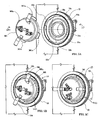
Figure 5D is an isometric view of the alpha and beta assemblies from the front with the alpha door latched. -
Figure 5E is an isometric view of the alpha and beta assemblies from the front with the alpha door unlatched. -
Figure 5F is an isometric view of the alpha and beta assemblies from the front with the alpha door open. -
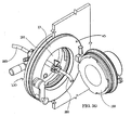
Figure 5G is an isometric view of the alpha and beta assemblies ofFigure 5F with a product hose and a filling hose attached. -
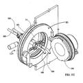
Figure 5H is an isometric view of the alpha and beta assemblies ofFigure 5F with dual product hoses and filling hoses attached. -
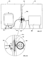
Figure 5I is an elevation view of the sterile liquid transfer port in the filling mode. -
Figure 5 J is a detailed elevation view ofFigure 5H showing the sterile liquid transfer port in the filling mode. - Overview. The SLTP isolates the clean environment and provides uncontaminated transfer of the sterile liquid product. Isolation of the clean environment is accomplished by a single step sterilization process. Uncontaminated transfer of the sterile liquid product is accomplished by the combination of the alpha assembly and the beta assembly.
- These key functions, including sterilization of the
beta assembly 100, isolation of thealpha assembly 10, and docking of thebeta assembly 100 to thealpha assembly 10, effectively isolate thedirty product suite 205 from the clean filling suite 204 (depicted inFigure 5I ) and enable the uncontaminated transfer of sterile liquid between the twosuites - Detailed Description. The SLTP includes two main components - the
alpha assembly 10 and thebeta assembly 100. -
Figure 1 is an isometric view of the alpha andbeta assemblies Figures 5I and 5J. Figure 5I is an elevation view of the SLTP in the filling mode, andFigure 5J is a detailed view of the SLTP in the filling mode. -
Figure 5I depicts an SLTP system in a relevant environment, where anisolation wall 201 separates afirst side 205 from asecond side 204. Thefirst side 205 can be a product suite having aproduct tank 202. Thesecond side 204 can be a filling suite havingfilling equipment 209. Thefirst side 205 can be a relatively "dirty" side, and can be classified as a Class 10,000 environment. Thesecond side 204 can be a relatively "clean" side, which can be classified as aClass 100 environment. Often it can be desirable to transfer liquid from theproduct tank 202 on the "dirty" side to fillingequipment 209 on the "clean" side without contamination of the liquid. An SLTP system can aid in such liquid transfer. - As shown in
Figures 1 ,2A , and5J , thealpha assembly 10 spans atransfer port 201b in anisolation window 201a. While thealpha assembly 10 can be primarily associated with the filling suite 204 (aClass 100 environment), as depicted inFigure 5I , thealpha assembly 10 extends into theproduct suite 205, which is the relatively "dirty" environment such that its rear portion is exposed to the Class 10,000 environment. Thebeta assembly 100, however is exclusively associated with theproduct suite 205, or the "dirty" side, in various embodiments, and docks to that rear portion of thealpha assembly 10. - The
alpha assembly 10 is configured to dock with thebeta assembly 100, which is demonstrated progressively fromFigure 5A to Figure 5F , and is described below. When thealpha 10 andbeta assemblies 100 are docked, product can be transferred from theproduct suite 205 to the filling suite 204 (Figure 5I ) without breaking containment. In the filling mode, thebeta assembly 100 is mounted in-line with thealpha assembly 10, as depicted inFigure 5A . Turning toFigures 5F and5G , when the alpha andbeta assemblies alpha door 16 is open, arigid product tube 109 extends into thefilling suite 204 and is ready for attachment to a sterileflexible filling hose 208. The sterileflexible filling hose 208 can deliver product (for example serum and vaccines) to commercially-sized containers for distribution. -
Figure 2A is an exploded view of thealpha assembly 10. Thealpha assembly 10 has afirst flange gasket 18,second flange gasket 18, aflange nut 17, analpha flange 11 and analpha door 16. Theflange gasket 18 is a seal between thealpha flange 11 and theisolation window 201a. The seal prevents leakage from a first side of theisolation window 201a to a second side of theisolation window 201 a, or the second side of theisolation window 201a to the first side of theisolation window 201a. Asecond flange gasket 18 is located on the opposite side of theisolation window 201a than that of thefirst flange gasket 18. Thesecond flange gasket 18 also serves the purpose of preventing leakage from theproduct suite 205 side of theisolation window 201a into thefilling suite 204 side of theisolation window 201a (depicted inFigure 5I ).Flange nut 17, located in the product suite side of the isolation window, secures thealpha flange 11 and the twoflange gaskets 18 to theisolation window 201a. Thealpha door 16 is disposed on thealpha flange 11. -
Figure 2B is an elevation view of thealpha assembly 10. Thealpha assembly 10 comprises analpha flange 11 and analpha door 16. Thealpha door 16 opens into one side of the isolation wall, which can be the filling suite side of the isolation wall depicted inFigure 5I . In a variety of embodiments, thealpha door 16 is generally closed, unless a filling operation is in progress. As such, thealpha door 16 also remains closed during sterilization, which can include sterilization of theproduct tank 202, such as the one depicted inFigure 5I . Sterilization generally takes place prior to initiation of a filling operation. -
Figure 2B also illustrates alatch 13 affixed toalpha door 16. A latch handle 14 engages withlatch 13. When the latch handle 14 is in the up position, latch 13 is locked, as is thealpha door 16, in one example embodiment. Thealpha door 16 is in a locked position whenever it is closed to avoid inadvertent contamination of clean side of the isolation wall, which can be the fillingsuite 204 fromFigure 5I , in one embodiment. - A
mechanical latch interlock 15 can prevent improper or unwanted operation of the SLTP. For example, such improper operations could include: opening thealpha door 16 before thebeta assembly 100 is docked with thealpha assembly 10; removing thebeta assembly 100 from thealpha assembly 10 when thealpha door 16 is open; and rotating the latch handle 14 of thealpha door 16 when thealpha door 16 is open.Latch interlock 15 can prevent accidental opening ofalpha door 16. Thealpha door 16 can be opened when thebeta assembly 100 is docked with thealpha assembly 10 due to automatic disengagement of thelatch interlock 15 by thebeta assembly 100. Thealpha door 16 can then be safely opened by rotation of thelatch handle 14, counter-clockwise 180°, in one embodiment, although other angles of rotation could be foreseen. -
Figure 2B also illustrates a hinge assembly 12 comprised of ahinge 12a, ahinge pivot block 12b, and ahinge pin 12c. Thehinge 12a is affixed toalpha door 16. The hinge assembly 12 provides a pivot connection between thealpha door 16 and thealpha flange 11 in a plane.Hinge 12a allows pivoting or rotation of thealpha door 16 around thehinge pin 12c to both open and close thealpha door 16. Thehinge pivot block 12b acts as a support guide to maintain thealpha door 16 in horizontal alignment during rotation or pivoting and during the time it is in the open position. -
Figure 2C is a cross-sectional view of thealpha assembly 10 ofFigure 2B . Thealpha assembly 10 is intended to maintain isolation of a first side of an isolation wall from a second side of an isolation wall, such as theproduct suite 205 from the fillingsuite 204 as depicted inFigure 5I . Such isolation is maintained regardless of whether the SLTP is in a sterilization mode or a filling mode. The installation of thealpha flange 11 is relatively permanent, while thebeta flange 101 is often inserted and removed. Now an example structure of thealpha assembly 10 will be described. - The
alpha assembly 10 is comprised of aflange 11,alpha door 16,bayonet receiver 11a,bayonet receiver channel 11b,flange nut 17,alpha seal 19,gasket 18 on the product suite side, andgasket 18 on the filling suite side. Thealpha seal 19 surrounds the inside of thealpha door 16 and seals thedoor 16 to theflange 11 upon closure. - Typically, an
isolation window 201a is installed in an opening in theisolation wall 201 and thealpha flange 11a is installed in thetransfer port 201b in theisolation wall 201. Thealpha flange 11 is inserted into atransfer port 201b (seeFigure 2A ) in anisolation wall 201. Prior to insertion offlange 11,gasket 18 on the filling suite side is put in place around theflange 11. Theisolation window 201a is used to monitor activity in the product and/or fillingsuites transfer port 201b,gasket 18 on theproduct suite 204 side is placed around theflange 11 andflange nut 17 is tightened down against theisolation window 201a or theisolation wall 201, as the case may be. -
Figure 2D is an elevational view of thealpha assembly 10 viewed from the rear.Alpha bayonet receiver 11a can also be referred to as a third connector set 11a, and is configured for mating engagement with abeta flange bayonet 101a when abeta assembly 100 is docked with thealpha assembly 10. As will be explained in more detail, below, thebeta flange bayonet 101a can be referred to as a first connector set. After initial docking, handles 104a (seeFigure 3C ) are used to rotate thebeta flange bayonets 101a counter-clockwise to releasably lock thebeta flange bayonets 101a under the alphabayonet receiver channel 11b.Alpha door bayonets 16a, which can be referred to as a fourth connector set 16a, are also configured for mating engagement with betacover bayonet receivers 102b, where the betacover bayonet receivers 102b can be referred to as a second connector set 102b.Handles 104a are used to further rotate the dockedbeta assembly 100 counter-clockwise to rotation of the beta flange releasably lock the alpha door bayonets 16a under the beta coverbayonet receiver channels 102c. -
Figure 2E is an isometric view of thealpha assembly 10 with thealpha door 16 closed. As previously mentioned, latch handle 14 is engaged withlatch 13. When latch handle 14 is in the up position it lockslatch 13 and therebyalpha door 16.Figure 2F is an isometric view of the alpha assembly with the alpha door open. To open thealpha door 16, latch handle 14 is rotated counter-clockwise 180°. -
Figure 3A is an isometric view of abeta assembly 100 from the front. The beta assembly is configured for connection with the alpha assembly from the first side of the isolation wall for sterile transfer of a product. The beta assembly generally has a housing having afirst side 101 andsecond side 102 that define an interior space, where thefirst side 101 can be abeta flange 101 and thesecond side 102 can be abeta cover 102. Afirst connector set 101a is defined on thefirst side 101 and a second connector set 102b is defined on thesecond side 102. Thebeta flange 101 can be releasably locked to thebeta cover 102. In at least one embodiment,flange bayonets 101a on thefirst side 101 of the housing are configured to engagebayonet receivers 111b of the docking cover. Thebeta assembly 100 also has abeta seal 103. - The
beta cover 102, includes a betacover end cap 102d that provides a closedinterior space 100a for therigid product tube 109 and a rigid drain tube 107 (shown inFigure 3B ). Theproduct tube 109 defines a passage from theinterior space 100a to outside of the housing. The closedinterior space 100a created by thecover end cap 102d is used in the sterilization mode. Sanitaryfitting clamp 110 connects aflexible product hose 203 to arigid product tube 109 for use during the sterilization process and for transfer of product during the filling process. Thebeta cover 102 is releasably locked to the beta flange by alignment of thebeta cover bayonets 102a with thebayonet cover receivers 101b of thebeta flange 100, followed by rotation of thebeta cover bayonets 102a under the beta coverbayonet receiver channels 101c. -
Beta flange 101 comprises at least one handle, in some embodiments two handles, andbrackets fitting clamp 110, andflange bayonets 101a. A first connector set 101a, which can be flange bayonets 101a, are aligned with thealpha bayonet receiver 11a during docking of thebeta assembly 100 with thealpha assembly 10.Cover seal 103 seals the betacover end cap 102 to thebeta flange 101 when thebeta cover 102 is connected tobeta flange 101.Handles 104a are used to rotate thebeta flange bayonets 101a counter-clockwise to releasably lock thebeta flange bayonets 101a under the alphabayonet receiver channels 11b.Alpha door bayonets 16a are configured for mating engagement with betacover bayonet receivers 102b. Rotation of thebeta flange bayonets 101a counter-clockwise also releasably locks the alpha door bayonets 16a under the beta flangebayonet receiver channels 102c. -
Figure 3B is an exploded, isometric view of thebeta assembly 100 from the front. In this view, theinterior space 100a of the beta flange can be clearly seen. A first hose connection device incorporating a combination of the sanitaryfitting clamp 110, the sanitaryfitting cap 106, and the sanitaryfitting seal 105 provides the connection between aflexible product hose 203 from theproduct tank 202 and therigid product tube 109 without the use of tools. A second hose connection device incorporates a combination of the sanitaryfitting clamp 110, sanitaryfitting seal 105, and sanitaryfitting cap 106, to provide a connection between aproduct tube 109 and aflexible filling hose 208 without the use of tools. Arigid drain tube 107 is shown in theinterior space 100a and is combined with the sanitaryfitting clamp 110, sanitaryfitting seal 105, and sanitaryfitting adaptor 108. It provides the connection between theinterior space 100a of thebeta assembly 100, therigid drain tube 107, and the flexiblesteam drain hose 207. Therigid drain tube 107 is used during the sterilization process. Therigid drain tube 107 defines a passage from theinterior space 100a to outside of the housing of thebeta assembly 100. -
Figure 3C is an elevational view of the beta assembly from the rear.Figure 3D is a cross-sectional view of thebeta assembly 100 ofFigure 3A . - The product port and the drain port, as shown at the rear of
Figure 3D , are capped with sanitaryfitting adaptors 106 for storage of the beta assembly. - A docking cover is generally located on a first side of an isolation wall and is configured for connection with a beta assembly during a sterilization process.
Figure 4A is an isometric view of theproduct tank 202 with thedocking cover 111 located on the product tank. Thedocking cover 111 may be located on a wall, bench, or other convenient place within theproduct suite 205. Thetank 202 is shown with wheels to indicate that thetank 202 is movable within theproduct suite 205 or movable to an entirely different product suit. It is typical that the SLTP will includemultiple product tanks 202 andbeta assemblies 100, yet only onealpha assembly 10. Thebeta assemblies 100 can also be located in amobile product suite 205. Theflexible product hose 203 is used as steam supply hose during sterilization and for transferring product to the beta assembly during filling. Eachhose fitting adaptor 108 when connected to thebeta assembly 100. -
Figure 4B is an isometric view of thebeta assembly 100 aligned for docking with thedocking cover 111. Thedocking cover 111 generally defines an opening to accommodate a portion of thehousing 100. Thedocking cover 111 is attached to a mountingplate 200 that in turn is attached to the outside of theproduct tank 202. Thebeta assembly 100,beta cover 102, and the mountingplate 200 are not connected in any way to the inside of thetank 202. Thedocking cover 111 hasbayonet receivers 111b, which can be referred to as a fifth connector set 111b, for engagement with the first connector set 101 a, orbeta flange bayonets 101a, on thebeta assembly 100. As will be understood by those of skill in the art, the first connector set 101 a andfifth connector set 111b can be a variety of mateable components that mate in a variety of different ways even though the connector sets described in the implementations disclosed herein are generally bayonet connections. In at least one embodiment, thebeta assembly 100 mounts to the docking cover without using any tools. - As shown in
Figure 4C , the betacover end cap 102d is inserted into thedocking cover opening 111a, which is in alignment with the mountingplate opening 200a. - After insertion of the
bayonets 101a into thebayonet receivers 111b, the beta assembly, as shown inFigure 4D , is mounted to the docking cover by rotating the beta assembly counter-clockwise, usinghandle assemblies 104, thereby rotating thebeta flange bayonets 101a in the docking coverbayonet receiver channels 111c. Sanitaryfitting adaptors 108 are also shown. -
Figure 4E is an isometric view of the beta assembly with aflexible product hose 203 and asteam drain hose 207. Theproduct hose 203 is connected to theproduct tube 109 of thebeta assembly 100. Likewise, thedrain hose 207 is connected to thedrain tube 107. -
Figures 4F and4G are isometric views of theproduct tank 202 and thebeta assembly 100 docked with thedocking cover 111 in the steam sterilization mode. Steam from a steam source is introduced into the top of theproduct tank 202 and passes through the flexiblesteam supply hose 206. Steam exits at the bottom of thetank 202 through theflexible product hose 203 and into thebeta assembly 100 viarigid product tube 109. Steam continues its travel through the interior 100a of thebeta assembly 100, out therigid drain tube 107, through the flexiblesteam drain hose 207, and into a condensate tank for disposal (not depicted). -
Figure 4G illustrates the detail of thebeta assembly interior 100a and the hose connections to thebeta assembly 100. As is viewable from the Figure, aseal 103 positioned between a portion of the beta cover and a portion of the beta flange, wherein the docking cover contacts the seal when the beta assembly is mated to the docking cover. By contacting the seal, the docking cover supports the seal during the sterilization process. The combination of the beta cover, beta flange and docking cover contact the seal on all sides of the seal. Without the cover, steam pressure during the sterilization process could cause the seal to be forced out of its seat, thereby possibly causing a leak which would be a failure of the sterilization process. With the docking cover, theseal 103 is further supported and a successful sterilization process is more likely. - The
beta assembly 100 is an integral part of the sterilization process. The sterilization system comprises the interior surfaces of the empty (i)product tank 202, (ii)flexible product hose 203, (iii) flexiblesteam supply hose 206, (iv) flexiblesteam drain hose 207, (v)beta assembly 100, and (vi) steam source. Thebeta assembly 100 comprises thebeta assembly interior 100a. The interior 100a, comprises the (i)rigid product tube 109, (ii)beta flange 101, (iii)beta cover 102, and (iv)outlet 107a of the rigid drain tube. - Exposure to elevated temperature and pressure for an extended period ensures sterilization of all of the internal surfaces of the sterilization system. The
alpha door 16 of thealpha assembly 10 is closed and sealed while sterilization takes place. Saturated steam at the elevated temperature and pressure is circulated through the sterilization system. The saturated steam is injected through the system at a working pressure of about 36.3 psi (depending upon the product type). The saturated steam temperature is about 150° Centigrade (depending upon the product type) when it enters the system. The required level of sterilization is maintained by continually monitoring the steam temperature at therigid drain tube 107 to ensure that the steam temperature at thedrain tube 107 remains at or about 150° Centigrade (depending upon the product type). After the system is sterilized, condensate is removed from the system by injecting hot, dry air through the system. - Upon completion of the sterilization process the
beta assembly 100 is undocked from thedocking cover 111 and docked with thealpha assembly 10. During the sterilization process theflexible product hose 203 was connected at the rear of thebeta assembly 100 to therigid product tube 109. To maintain sterilization, theflexible product hose 203 must remain connected. The flexiblesteam drain hose 207 and the sanitaryfitting adaptor 108 must be removed from therigid drain tube 107 and replaced with the sanitaryfitting cap 106. -
Figure 5A is an isometric view of the beta andalpha assemblies first connector set 101a on thefirst side 100 and a second connector set 102b on the second side 102 (visible inFigure 3A , for example), where thefirst connector set 101a is configured to be mated with athird connector 111a set on thealpha assembly 10 and the second connector set 102b is configured to be mated with a fourth connector set 16a on thealpha assembly 10. The first connector set 101a can also be configured to be mated with a fifth connector set on a product tank as described above in the discussion ofFigure 4B-4E . In a variety of embodiments, including the one depicted and described herein, the first, second, third, fourth and fifth (described in the discussion ofFigure 4A ), are bayonet connections.Figure 5B is an isometric view of the beta assembly with thebeta flange bayonets 101a received in thealpha bayonet receivers 11a. Those skilled in the art will appreciate that a variety of other types of connections can be employed and still remain in the scope of the technology disclosed herein. - As shown in
Figure 5C , thebeta flange bayonets 101a are then rotated counter-clockwise under the alphabayonet receiver channels 11b. The first 101a and third 111b connector sets can be configured to engage and disengage upon rotation with respect to each other. Likewise, the second and fourth connector sets can be configured to engage and disengage upon rotation with respect to each other, although other means of engaging and disengaging the first and third connector sets can be employed. -
Figure 5D is an isometric view of the alpha andbeta assemblies alpha door 16 latched. -
Figure 5E is an isometric view of the alpha andbeta assemblies alpha door 16 unlatched. -
Figure 5F is an isometric view of the alpha and beta assemblies with thealpha door 16 open, thereby allowing access to the sanitaryfitting adaptor 108 for attachment to theflexible filling hose 208. -
Figure 5G is an isometric view of alpha andbeta assemblies rigid product tube 109.Figure 5H is an isometric view of the alpha andbeta assemblies rigid product tubes 109. In certain cases, two substances may be differentially metered from separate product tanks into therespective product tubes 109 for combination into a two-part medicant. In this manner any number of individual product tubes may be employed to mix the various substances together. InFigures 5G and5H , the rear of thebeta cover 102 is captured by thealpha door 16 when thebeta assembly 100 is engaged with thealpha assembly 10. Theflexible filling hose 208 extends into thefilling suite 204. -
Figure 5I is an elevation view of the SLTP in the filling mode. -
Figure 5J is a detailed view of the SLTP in the filling mode. Transfer of product to thefilling suite 204 may be accomplished by pumping, gravity feed, or pressurization of theproduct tank 202. Typically, product is stored under pressure. - As shown by
Figures 5A-5J , thealpha assembly 10 and thebeta assembly 100 implement the process of uncontaminated transfer of sterile liquid product. Theproduct suite 205 is always isolated from the fillingsuite 204 by analpha assembly 10. Thealpha assembly 10 has an interface for docking thebeta assembly 100. Thealpha assembly 10 is configured so thealpha door 16 cannot be opened without thebeta assembly 100 docked to thealpha assembly 10. This ensures that theproduct suite 205 will not contaminate thefilling suite 204. - To transfer sterile liquid product from the
product tank 202 to the fillingsuit 204, (i) the flexiblesteam supply hose 206 is shut-off from theproduct tank 202, (ii) the flexiblesteam drain hose 207 is shut-off from the sanitaryfitting adaptor 108 on thebeta assembly 100, the adaptor is removed from the beta assembly, and theadaptor 108 is replaced with a plug; and (iii) thebeta assembly 100, with its attachedflexible product hose 203, is undocked from thedocking cover 111 and docked with thealpha assembly 10. And theproduct tank 202 is filled with product. - Rotating the
beta assembly 100 and docking it to thealpha assembly 10 causes four events to simultaneously occur. First, during docking thebeta flange 101 becomes rigidly attached to thealpha flange 11. Second, docking causes thebeta cover 102 to become detached from the beta flange. Third, thebeta cover 102 whose external surfaces have been exposed to theproduct suite 205 becomes attached to thealpha door 16. All external surfaces are sealed inside thealpha door 16 by thealpha seal 19. Finally, the docking process disengages the interlock mechanism on thealpha assembly 10 thus enabling thealpha door 16 to be safely opened. Once opened, thebeta cover 102 becomes separated from thebeta flange 101 thereby exposing the sterilerigid product tube 109, sterile sanitaryfitting seal 105, sterile sanitaryfitting adaptor 108, and sterile sanitaryfitting clamp 110 to theclean filling suite 204. Attachment of aflexible filling hose 208 enables transfer of the sterile liquid without contamination from theproduct suite 205 into thefilling suite 204 and subsequently into thefilling equipment 209. - Aspects of the invention may include any of the following.
- 1. A sterilization system for a sterile liquid transfer port system comprising:
- (a) an isolation wall having a first and second side;
- (b) an alpha assembly spanning a port in the isolation wall between the first and second sides of the isolation wall;
- (c) a beta assembly configured for connection with the alpha assembly from the first side of the isolation wall for sterile transfer of a product, the beta assembly comprising:
- a. a housing having a first side and a second side and defining an interior space;
- b. a product tube defining a passage from the interior space to an outside of the housing;
- c. a drain tube defining a passage from the interior space to the outside of the housing;
- d. a first connector set on the first side and a second connector set on the second side, where the first connector set is configured to be mated with a third connector set on the alpha assembly and the second connector set is configured to be mated with a fourth connector set on the alpha assembly; and
- (d) a docking cover on a first side of the isolation wall comprising a fifth connector set that is configured to be mated to the first connector set of the housing, wherein the docking cover is configured for connection to the beta assembly during a sterilization process.
- 2. The system of aspect 1 wherein the housing of the beta assembly comprises at least one handle.
- 3. The system of aspect 1 wherein the housing of the beta assembly comprises two handles.
- 4. The system of aspect 1 wherein the first and third connector sets are configured to engage and disengage upon rotation with respect to each other, and wherein the second and fourth connector sets are configured to engage and disengage upon rotation with respect to each other.
- 5. The system of aspect 1 wherein the first, second, third, fourth and fifth connector sets are bayonet connections.
- 6. The system of aspect 1 wherein the housing of the beta assembly further comprises:
- a beta cover; and
- a beta flange releasably locked to the cover and providing the interior space when locked to the cover.
- 7. The system of aspect 6 wherein the housing of the beta assembly further comprises a seal positioned between a portion of the beta cover and a portion of the beta flange, wherein the docking cover contacts the seal when the beta assembly is mated to the docking cover.
- 8. The system of aspect 1 wherein the product tube comprises a first hose connection device configured to connect a first flexible hose to the product tube without using tools, and wherein the drain tube comprises a second hose connection device configured to connect a second flexible hose to the drain tube without using tools.
- 9. The system of aspect 1, the system further comprising a product tank located on the first side of the isolation wall, the product tank comprising two ports and configured to connect to the product tube of the beta assembly.
- 10. The system of aspect 9, wherein the docking cover is mounted on the product tank.
- 11. The system of aspect 1, wherein the docking cover defines an opening to accommodate a portion of the housing.
- 12. An assembly for a sterile liquid transfer port system comprising:
- a housing having a first side and a second side and defining an interior space;
- a product tube defining a passage from the interior space to an outside of the housing;
- a drain tube defining a passage from the interior space to the outside of the housing;
- a first bayonet connection on the first side and second bayonet connection on the second side, where the first bayonet connection is configured to be mated with a third bayonet connection on an alpha assembly and the second bayonet connection is configured to be mated with a fourth bayonet connection on the alpha assembly; and
wherein the first bayonet connection is further configured to be mated with a fifth bayonet connection on a docking cover.
- 13. The assembly of aspect 12 wherein the housing comprises at least one handle.
- 14. The assembly of aspect 12 wherein the housing comprises two handles.
- 15. The assembly of aspect 12 wherein the housing further comprises a beta cover and a beta flange releasably locked to the cover and providing the interior space when locked to the cover.
- 16. The assembly of
aspect 15 wherein the beta cover and beta flange are configured to engage and disengage upon rotation with respect to each other. - 17. The assembly of
aspect 15, wherein the beta flange comprises at least one a handle. - 18. The assembly of
aspect 15 wherein the housing further comprises a seal positioned between a portion of the beta cover and a portion of the beta flange, wherein the docking cover contacts the seal when the beta assembly is mated to the docking cover. - 19. The assembly of aspect 12 wherein the product tube comprises a first hose connection device configured to connect a flexible hose to the product tube without using tools, and wherein the drain tube comprises a second hose connection device configured to connect a flexible hose to the drain tube without using tools.
- 20. A beta assembly for a sterile liquid transfer port system comprising:
- a cover;
- a flange releasably locked to the cover providing interior space;
- a product tube for use during the sterilization process and for transfer of product during a filling process;
- a drain tube in the interior space to be used during a sterilization process flange bayonets to be aligned with an alpha assembly;
- cover bayonet receivers configured for mating engagement with alpha door bayonets.
- 21. The beta assembly of aspect 20, further comprising handles to rotate flange bayonets.
- 22. The flange bayonets of aspect 20 further configured to engage with a docking cover.
- 23. The flange bayonets of aspect 20, further configured to engage with a docking cover, wherein the docking cover is located at one of the group consisting of: a wall, a bench, and a product tank.
- 24. The beta assembly of aspect 20, further comprising a fitting seal providing connection between a product hose and the product tube.
- 25. The beta assembly of aspect 20, wherein docking the beta assembly to the alpha assembly causes the cover to become detached from the flange.
- 26. The beta assembly of aspect 20 configured such that steam exits a tank into the product tube, through the interior space, and out the drain tube in a sterilization mode.
- 27. The beta assembly of aspect 20, further comprising two or more product tubes.
- 28. A method of sterilizing a system comprising:
- (a) mounting a beta assembly to a docking cover, wherein the beta assembly comprises a housing having a first side and a second side and defining an interior space, a product tube defining a passage from the interior space to the outside of the housing, and a drain tube defining a passage from the interior space to the outside of the housing;
- (b) connecting a product hose from a tank to a product tube of the beta assembly;
- (c) connecting a drain hose to a drain tube of the beta assembly; and
- (d) passing sterilization fluid through both the tank, the supply hose and the beta assembly.
- 29. The method of aspect 28 wherein the sterilization fluid is steam.
- 30. The method of aspect 28 wherein the docking cover is mounted on the tank.
- 31. The method of aspect 28 wherein the housing of the beta assembly comprises at least one handle.
- 32. The method of aspect 28 wherein the beta assembly mounts to the docking cover without using any tools.
- 33. The method of aspect 28 wherein the beta assembly mounts to the docking cover by rotation of the beta assembly with respect to the docking cover.
- 34. The method of aspect 28 wherein the beta assembly mounts to the docking cover with a bayonet connection.
- 35. A sterilization assembly comprising:
- a housing having a first side and a second side, and defining an interior space, the housing further comprising a product tube defining a passage from the interior space to the outside of the housing and a drain tube defining a passage from the interior space to the outside of the housing;
- a docking cover having bayonet receivers; and
- flange bayonets on the first side of the housing configured to engage the bayonet receivers of the docking cover.
- 36. The assembly of aspect 35 wherein the housing comprises at least one handle.
- 37. The assembly of aspect 35 wherein the housing comprises two handles.
- 38. The assembly of aspect 36 wherein the housing and the docking cover are configured to engage and disengage upon rotation with respect to each other.
- 39. The assembly of aspect 35 wherein the housing further comprises:
- a beta cover; and
- a beta flange releasably locked to the cover and providing the interior space when locked to the cover.
- 40. The assembly of aspect 35 wherein the housing further comprises a seal positioned between a portion of the beta cover and a portion of the beta flange, wherein the docking cover contacts the seal when the beta assembly is mated to the docking cover.
- 41. The assembly of aspect 35 wherein the product tube comprises a first hose connection device configured to connect a first flexible hose to the product tube without using tools, and wherein the drain tube comprises a second hose connection device configured to connect a second flexible hose to the drain tube without using tools.
- 42. The assembly of aspect 35, wherein the docking cover defines an opening to accommodate a portion of the housing.
Claims (15)
- An assembly for a sterile liquid transfer port system comprising:a housing having a first side and a second side and defining an interior space;a product tube defining a passage from the interior space to an outside of the housing;a drain tube defining a passage from the interior space to the outside of the housing;a first bayonet connection on the first side and second bayonet connection on the second side, where the first bayonet connection is configured to be mated with a third bayonet connection on an alpha assembly and the second bayonet connection is configured to be mated with a fourth bayonet connection on the alpha assembly; andwherein the first bayonet connection is further configured to be mated with a fifth bayonet connection on a docking cover.
- The assembly of claim 1 wherein the housing comprises two handles.
- The assembly of claim 1 wherein the housing further comprises a beta cover and a beta flange releasably locked to the cover and providing the interior space when locked to the cover.
- The assembly of claim 3 wherein the beta cover and beta flange are configured to engage and disengage upon rotation with respect to each other.
- The assembly of claim 3, wherein the beta flange comprises at least one a handle.
- The assembly of claim 3 wherein the housing further comprises a seal positioned between a portion of the beta cover and a portion of the beta flange, wherein the docking cover contacts the seal when the beta assembly is mated to the docking cover.
- The assembly of claim 1 wherein the product tube comprises a first hose connection device configured to connect a flexible hose to the product tube without using tools, and wherein the drain tube comprises a second hose connection device configured to connect a flexible hose to the drain tube without using tools.
- A beta assembly for a sterile liquid transfer port system comprising:a cover;a flange releasably locked to the cover providing interior space;a product tube for use during the sterilization process and for transfer of product during a filling process;a drain tube in the interior space to be used during a sterilization process;flange bayonets to be aligned with an alpha assembly; andcover bayonet receivers configured for mating engagement with alpha door bayonets.
- The beta assembly of claim 8, further comprising handles to rotate flange bayonets.
- The beta assembly of claim 8 in which the flange bayonets are further configured to engage with a docking cover.
- The beta assembly of claim 8 in which the flange bayonets are further configured to engage with a docking cover, wherein the docking cover is located at one of the group consisting of: a wall, a bench, and a product tank.
- The beta assembly of claim 8, further comprising a fitting seal providing connection between a product hose and the product tube.
- The beta assembly of claim 8, wherein docking the beta assembly to the alpha assembly causes the cover to become detached from the flange.
- The beta assembly of claim 8 configured such that steam exits a tank into the product tube, through the interior space, and out the drain tube in a sterilization mode.
- The beta assembly of claim 8, further comprising two or more product tubes.
Applications Claiming Priority (2)
| Application Number | Priority Date | Filing Date | Title |
|---|---|---|---|
| US12/245,603 US20100084045A1 (en) | 2008-10-03 | 2008-10-03 | Sterile liquid transfer port |
| EP09736351.9A EP2379120B1 (en) | 2008-10-03 | 2009-10-05 | Sterile liquid transfer port |
Related Parent Applications (2)
| Application Number | Title | Priority Date | Filing Date |
|---|---|---|---|
| EP09736351.9A Division EP2379120B1 (en) | 2008-10-03 | 2009-10-05 | Sterile liquid transfer port |
| EP09736351.9A Division-Into EP2379120B1 (en) | 2008-10-03 | 2009-10-05 | Sterile liquid transfer port |
Publications (2)
| Publication Number | Publication Date |
|---|---|
| EP2735317A1 true EP2735317A1 (en) | 2014-05-28 |
| EP2735317B1 EP2735317B1 (en) | 2015-12-30 |
Family
ID=41404106
Family Applications (2)
| Application Number | Title | Priority Date | Filing Date |
|---|---|---|---|
| EP14155832.0A Not-in-force EP2735317B1 (en) | 2008-10-03 | 2009-10-05 | Sterile liquid transfer port |
| EP09736351.9A Not-in-force EP2379120B1 (en) | 2008-10-03 | 2009-10-05 | Sterile liquid transfer port |
Family Applications After (1)
| Application Number | Title | Priority Date | Filing Date |
|---|---|---|---|
| EP09736351.9A Not-in-force EP2379120B1 (en) | 2008-10-03 | 2009-10-05 | Sterile liquid transfer port |
Country Status (4)
| Country | Link |
|---|---|
| US (2) | US20100084045A1 (en) |
| EP (2) | EP2735317B1 (en) |
| JP (1) | JP5753088B2 (en) |
| WO (1) | WO2010040126A2 (en) |
Cited By (1)
| Publication number | Priority date | Publication date | Assignee | Title |
|---|---|---|---|---|
| WO2022063667A1 (en) * | 2020-09-23 | 2022-03-31 | Syntegon Technology Gmbh | Beta component of a transfer system for a sterile isolation region, sterile isolation region, aseptic filling system, and method for operating such a filling system |
Families Citing this family (8)
| Publication number | Priority date | Publication date | Assignee | Title |
|---|---|---|---|---|
| US20100084045A1 (en) | 2008-10-03 | 2010-04-08 | Adams Richard H | Sterile liquid transfer port |
| CL2010000644A1 (en) * | 2010-06-18 | 2011-01-14 | Andesocean S A | Sterilization equipment used in the loading of containers for the transport of products in an aseptic way, comprising a portable boiler, pre-washing systems using chemicals, circulation water and hot water, a pump for washing, steam for sterilizing and hoses flexible; and washing method. |
| FR3016794B1 (en) * | 2014-01-24 | 2018-03-02 | Pierre Fabre Dermo-Cosmetique | DEVICE AND METHOD FOR TRANSFERRING A STERILE PRODUCT BETWEEN TWO CONTAINERS |
| GB2542123A (en) * | 2015-09-08 | 2017-03-15 | Chargepoint Tech Ltd | Transfer device |
| BE1023860B1 (en) * | 2016-02-18 | 2017-08-22 | Aseptic Technologies S.A. | Connection system |
| DE102020102765A1 (en) * | 2020-02-04 | 2021-08-05 | Groninger & Co. Gmbh | Method for transferring at least one filling needle of a number of filling needles into an aseptic isolator |
| DE102024103510A1 (en) * | 2024-02-08 | 2025-08-14 | Syntegon Technology Gmbh | Transfer system for use in a pharmaceutical barrier system, in particular an isolator, beta component for use in a transfer system, barrier system, in particular isolator and production plant |
| CN119218472B (en) * | 2024-11-15 | 2025-09-26 | 四川科伦药业股份有限公司 | A double butterfly valve sterile drug transfer system and sterile drug transfer method |
Citations (5)
| Publication number | Priority date | Publication date | Assignee | Title |
|---|---|---|---|---|
| US4347877A (en) * | 1980-04-21 | 1982-09-07 | Jakob Hoiss | Apparatus for aseptically discharging flowable substances |
| GB2237816A (en) * | 1989-11-09 | 1991-05-15 | Cambridge Isolation Tech | Isolator transfer containers |
| EP0661062A2 (en) * | 1993-12-15 | 1995-07-05 | Total Process Containment Limited | Aseptic liquid barrier transfer coupling |
| EP0830896A2 (en) * | 1996-09-19 | 1998-03-25 | The Boc Group, Inc. | Transfer port system |
| WO2007044347A2 (en) * | 2005-10-05 | 2007-04-19 | Delaware Capital Formation, Inc. | Hazardous waste transfer port system and storage container |
Family Cites Families (6)
| Publication number | Priority date | Publication date | Assignee | Title |
|---|---|---|---|---|
| US5460439A (en) * | 1994-01-07 | 1995-10-24 | Delaware Capital Formation, Inc. | Sealed transfer system |
| US5523519A (en) * | 1994-07-14 | 1996-06-04 | Delaware Capital Formation, Inc. | System for facilitating safe transfer of hazardous material |
| US5662581A (en) * | 1995-01-05 | 1997-09-02 | Delaware Capital Formation, Inc. | Easily sterilizable glove system |
| FR2735201B1 (en) * | 1995-06-08 | 1997-08-29 | Calhene | LID TO BE PLACED ON A DOOR OF A CONTAINER TO BE STERILIZED |
| US7044347B1 (en) * | 2003-03-06 | 2006-05-16 | Fabio Pedrini | Interlock arrangement for an extendible and retractable stabilizer for use in a bicycle carrier |
| US20100084045A1 (en) | 2008-10-03 | 2010-04-08 | Adams Richard H | Sterile liquid transfer port |
-
2008
- 2008-10-03 US US12/245,603 patent/US20100084045A1/en not_active Abandoned
-
2009
- 2009-10-05 WO PCT/US2009/059532 patent/WO2010040126A2/en not_active Ceased
- 2009-10-05 US US13/122,222 patent/US9198992B2/en active Active
- 2009-10-05 EP EP14155832.0A patent/EP2735317B1/en not_active Not-in-force
- 2009-10-05 JP JP2011530289A patent/JP5753088B2/en active Active
- 2009-10-05 EP EP09736351.9A patent/EP2379120B1/en not_active Not-in-force
Patent Citations (5)
| Publication number | Priority date | Publication date | Assignee | Title |
|---|---|---|---|---|
| US4347877A (en) * | 1980-04-21 | 1982-09-07 | Jakob Hoiss | Apparatus for aseptically discharging flowable substances |
| GB2237816A (en) * | 1989-11-09 | 1991-05-15 | Cambridge Isolation Tech | Isolator transfer containers |
| EP0661062A2 (en) * | 1993-12-15 | 1995-07-05 | Total Process Containment Limited | Aseptic liquid barrier transfer coupling |
| EP0830896A2 (en) * | 1996-09-19 | 1998-03-25 | The Boc Group, Inc. | Transfer port system |
| WO2007044347A2 (en) * | 2005-10-05 | 2007-04-19 | Delaware Capital Formation, Inc. | Hazardous waste transfer port system and storage container |
Cited By (1)
| Publication number | Priority date | Publication date | Assignee | Title |
|---|---|---|---|---|
| WO2022063667A1 (en) * | 2020-09-23 | 2022-03-31 | Syntegon Technology Gmbh | Beta component of a transfer system for a sterile isolation region, sterile isolation region, aseptic filling system, and method for operating such a filling system |
Also Published As
| Publication number | Publication date |
|---|---|
| EP2379120A2 (en) | 2011-10-26 |
| WO2010040126A3 (en) | 2010-09-10 |
| US20100084045A1 (en) | 2010-04-08 |
| EP2379120B1 (en) | 2014-04-23 |
| JP2012504475A (en) | 2012-02-23 |
| US20110256021A1 (en) | 2011-10-20 |
| WO2010040126A2 (en) | 2010-04-08 |
| EP2735317B1 (en) | 2015-12-30 |
| JP5753088B2 (en) | 2015-07-22 |
| US9198992B2 (en) | 2015-12-01 |
Similar Documents
| Publication | Publication Date | Title |
|---|---|---|
| EP2379120B1 (en) | Sterile liquid transfer port | |
| US12097476B2 (en) | Compounder apparatus | |
| JP3246037U (en) | Dry disconnect cartridge and dual lumen needle for automatic drug dispenser | |
| AU2014307860B2 (en) | Container for transporting and storing a liquid | |
| KR20180094017A (en) | Apparatus and method for protecting and unprotecting a fluid path in a controlled environmental enclosure | |
| US20180078930A1 (en) | Customizable mounting interface for a sealed transfer port | |
| US20230364619A1 (en) | Beta component of a transfer system for a sterile isolation region, sterile isolation region, aseptic filling system, and a method of operating such a filling system | |
| US20160206511A1 (en) | Compounding systems and methods for safe medicament transport | |
| EP3033298A1 (en) | A container for transporting and storing a liquid | |
| US20240423873A1 (en) | Convenience kits for preparing medicine with an assured level of safety | |
| Lechiffre et al. | Rapid transfer port system: the key element for contained enclosures in advanced aseptic processing | |
| Lechiffre et al. | 9 Rapid transfer port system: the key element for contained enclosures in advanced | |
| Partington | Aseptic processing transfer systems |
Legal Events
| Date | Code | Title | Description |
|---|---|---|---|
| PUAI | Public reference made under article 153(3) epc to a published international application that has entered the european phase |
Free format text: ORIGINAL CODE: 0009012 |
|
| 17P | Request for examination filed |
Effective date: 20140219 |
|
| AC | Divisional application: reference to earlier application |
Ref document number: 2379120 Country of ref document: EP Kind code of ref document: P |
|
| AK | Designated contracting states |
Kind code of ref document: A1 Designated state(s): AT BE BG CH CY CZ DE DK EE ES FI FR GB GR HR HU IE IS IT LI LT LU LV MC MK MT NL NO PL PT RO SE SI SK SM TR |
|
| GRAJ | Information related to disapproval of communication of intention to grant by the applicant or resumption of examination proceedings by the epo deleted |
Free format text: ORIGINAL CODE: EPIDOSDIGR1 |
|
| GRAP | Despatch of communication of intention to grant a patent |
Free format text: ORIGINAL CODE: EPIDOSNIGR1 |
|
| INTG | Intention to grant announced |
Effective date: 20150619 |
|
| GRAS | Grant fee paid |
Free format text: ORIGINAL CODE: EPIDOSNIGR3 |
|
| GRAA | (expected) grant |
Free format text: ORIGINAL CODE: 0009210 |
|
| AC | Divisional application: reference to earlier application |
Ref document number: 2379120 Country of ref document: EP Kind code of ref document: P |
|
| AK | Designated contracting states |
Kind code of ref document: B1 Designated state(s): AT BE BG CH CY CZ DE DK EE ES FI FR GB GR HR HU IE IS IT LI LT LU LV MC MK MT NL NO PL PT RO SE SI SK SM TR |
|
| REG | Reference to a national code |
Ref country code: GB Ref legal event code: FG4D |
|
| REG | Reference to a national code |
Ref country code: CH Ref legal event code: EP |
|
| REG | Reference to a national code |
Ref country code: AT Ref legal event code: REF Ref document number: 767161 Country of ref document: AT Kind code of ref document: T Effective date: 20160115 |
|
| REG | Reference to a national code |
Ref country code: IE Ref legal event code: FG4D |
|
| REG | Reference to a national code |
Ref country code: DE Ref legal event code: R096 Ref document number: 602009035491 Country of ref document: DE |
|
| REG | Reference to a national code |
Ref country code: LT Ref legal event code: MG4D |
|
| PG25 | Lapsed in a contracting state [announced via postgrant information from national office to epo] |
Ref country code: HR Free format text: LAPSE BECAUSE OF FAILURE TO SUBMIT A TRANSLATION OF THE DESCRIPTION OR TO PAY THE FEE WITHIN THE PRESCRIBED TIME-LIMIT Effective date: 20151230 Ref country code: LT Free format text: LAPSE BECAUSE OF FAILURE TO SUBMIT A TRANSLATION OF THE DESCRIPTION OR TO PAY THE FEE WITHIN THE PRESCRIBED TIME-LIMIT Effective date: 20151230 Ref country code: NO Free format text: LAPSE BECAUSE OF FAILURE TO SUBMIT A TRANSLATION OF THE DESCRIPTION OR TO PAY THE FEE WITHIN THE PRESCRIBED TIME-LIMIT Effective date: 20160330 |
|
| REG | Reference to a national code |
Ref country code: NL Ref legal event code: MP Effective date: 20151230 |
|
| REG | Reference to a national code |
Ref country code: AT Ref legal event code: MK05 Ref document number: 767161 Country of ref document: AT Kind code of ref document: T Effective date: 20151230 |
|
| PG25 | Lapsed in a contracting state [announced via postgrant information from national office to epo] |
Ref country code: LV Free format text: LAPSE BECAUSE OF FAILURE TO SUBMIT A TRANSLATION OF THE DESCRIPTION OR TO PAY THE FEE WITHIN THE PRESCRIBED TIME-LIMIT Effective date: 20151230 Ref country code: FI Free format text: LAPSE BECAUSE OF FAILURE TO SUBMIT A TRANSLATION OF THE DESCRIPTION OR TO PAY THE FEE WITHIN THE PRESCRIBED TIME-LIMIT Effective date: 20151230 Ref country code: SE Free format text: LAPSE BECAUSE OF FAILURE TO SUBMIT A TRANSLATION OF THE DESCRIPTION OR TO PAY THE FEE WITHIN THE PRESCRIBED TIME-LIMIT Effective date: 20151230 Ref country code: GR Free format text: LAPSE BECAUSE OF FAILURE TO SUBMIT A TRANSLATION OF THE DESCRIPTION OR TO PAY THE FEE WITHIN THE PRESCRIBED TIME-LIMIT Effective date: 20160331 |
|
| PG25 | Lapsed in a contracting state [announced via postgrant information from national office to epo] |
Ref country code: NL Free format text: LAPSE BECAUSE OF FAILURE TO SUBMIT A TRANSLATION OF THE DESCRIPTION OR TO PAY THE FEE WITHIN THE PRESCRIBED TIME-LIMIT Effective date: 20151230 |
|
| PG25 | Lapsed in a contracting state [announced via postgrant information from national office to epo] |
Ref country code: ES Free format text: LAPSE BECAUSE OF FAILURE TO SUBMIT A TRANSLATION OF THE DESCRIPTION OR TO PAY THE FEE WITHIN THE PRESCRIBED TIME-LIMIT Effective date: 20151230 Ref country code: IT Free format text: LAPSE BECAUSE OF FAILURE TO SUBMIT A TRANSLATION OF THE DESCRIPTION OR TO PAY THE FEE WITHIN THE PRESCRIBED TIME-LIMIT Effective date: 20151230 Ref country code: CZ Free format text: LAPSE BECAUSE OF FAILURE TO SUBMIT A TRANSLATION OF THE DESCRIPTION OR TO PAY THE FEE WITHIN THE PRESCRIBED TIME-LIMIT Effective date: 20151230 |
|
| PG25 | Lapsed in a contracting state [announced via postgrant information from national office to epo] |
Ref country code: EE Free format text: LAPSE BECAUSE OF FAILURE TO SUBMIT A TRANSLATION OF THE DESCRIPTION OR TO PAY THE FEE WITHIN THE PRESCRIBED TIME-LIMIT Effective date: 20151230 Ref country code: AT Free format text: LAPSE BECAUSE OF FAILURE TO SUBMIT A TRANSLATION OF THE DESCRIPTION OR TO PAY THE FEE WITHIN THE PRESCRIBED TIME-LIMIT Effective date: 20151230 Ref country code: IS Free format text: LAPSE BECAUSE OF FAILURE TO SUBMIT A TRANSLATION OF THE DESCRIPTION OR TO PAY THE FEE WITHIN THE PRESCRIBED TIME-LIMIT Effective date: 20160430 Ref country code: SM Free format text: LAPSE BECAUSE OF FAILURE TO SUBMIT A TRANSLATION OF THE DESCRIPTION OR TO PAY THE FEE WITHIN THE PRESCRIBED TIME-LIMIT Effective date: 20151230 Ref country code: RO Free format text: LAPSE BECAUSE OF FAILURE TO SUBMIT A TRANSLATION OF THE DESCRIPTION OR TO PAY THE FEE WITHIN THE PRESCRIBED TIME-LIMIT Effective date: 20151230 Ref country code: SK Free format text: LAPSE BECAUSE OF FAILURE TO SUBMIT A TRANSLATION OF THE DESCRIPTION OR TO PAY THE FEE WITHIN THE PRESCRIBED TIME-LIMIT Effective date: 20151230 Ref country code: PT Free format text: LAPSE BECAUSE OF FAILURE TO SUBMIT A TRANSLATION OF THE DESCRIPTION OR TO PAY THE FEE WITHIN THE PRESCRIBED TIME-LIMIT Effective date: 20160502 Ref country code: PL Free format text: LAPSE BECAUSE OF FAILURE TO SUBMIT A TRANSLATION OF THE DESCRIPTION OR TO PAY THE FEE WITHIN THE PRESCRIBED TIME-LIMIT Effective date: 20151230 |
|
| REG | Reference to a national code |
Ref country code: DE Ref legal event code: R097 Ref document number: 602009035491 Country of ref document: DE |
|
| REG | Reference to a national code |
Ref country code: FR Ref legal event code: PLFP Year of fee payment: 8 |
|
| PG25 | Lapsed in a contracting state [announced via postgrant information from national office to epo] |
Ref country code: DK Free format text: LAPSE BECAUSE OF FAILURE TO SUBMIT A TRANSLATION OF THE DESCRIPTION OR TO PAY THE FEE WITHIN THE PRESCRIBED TIME-LIMIT Effective date: 20151230 |
|
| PLBE | No opposition filed within time limit |
Free format text: ORIGINAL CODE: 0009261 |
|
| STAA | Information on the status of an ep patent application or granted ep patent |
Free format text: STATUS: NO OPPOSITION FILED WITHIN TIME LIMIT |
|
| 26N | No opposition filed |
Effective date: 20161003 |
|
| PG25 | Lapsed in a contracting state [announced via postgrant information from national office to epo] |
Ref country code: BE Free format text: LAPSE BECAUSE OF FAILURE TO SUBMIT A TRANSLATION OF THE DESCRIPTION OR TO PAY THE FEE WITHIN THE PRESCRIBED TIME-LIMIT Effective date: 20151230 |
|
| PG25 | Lapsed in a contracting state [announced via postgrant information from national office to epo] |
Ref country code: SI Free format text: LAPSE BECAUSE OF FAILURE TO SUBMIT A TRANSLATION OF THE DESCRIPTION OR TO PAY THE FEE WITHIN THE PRESCRIBED TIME-LIMIT Effective date: 20151230 |
|
| REG | Reference to a national code |
Ref country code: CH Ref legal event code: PL |
|
| REG | Reference to a national code |
Ref country code: IE Ref legal event code: MM4A |
|
| PG25 | Lapsed in a contracting state [announced via postgrant information from national office to epo] |
Ref country code: LI Free format text: LAPSE BECAUSE OF NON-PAYMENT OF DUE FEES Effective date: 20161031 Ref country code: CH Free format text: LAPSE BECAUSE OF NON-PAYMENT OF DUE FEES Effective date: 20161031 |
|
| PG25 | Lapsed in a contracting state [announced via postgrant information from national office to epo] |
Ref country code: LU Free format text: LAPSE BECAUSE OF NON-PAYMENT OF DUE FEES Effective date: 20161005 |
|
| REG | Reference to a national code |
Ref country code: FR Ref legal event code: PLFP Year of fee payment: 9 |
|
| PG25 | Lapsed in a contracting state [announced via postgrant information from national office to epo] |
Ref country code: IE Free format text: LAPSE BECAUSE OF NON-PAYMENT OF DUE FEES Effective date: 20161005 |
|
| PG25 | Lapsed in a contracting state [announced via postgrant information from national office to epo] |
Ref country code: CY Free format text: LAPSE BECAUSE OF FAILURE TO SUBMIT A TRANSLATION OF THE DESCRIPTION OR TO PAY THE FEE WITHIN THE PRESCRIBED TIME-LIMIT Effective date: 20151230 Ref country code: HU Free format text: LAPSE BECAUSE OF FAILURE TO SUBMIT A TRANSLATION OF THE DESCRIPTION OR TO PAY THE FEE WITHIN THE PRESCRIBED TIME-LIMIT; INVALID AB INITIO Effective date: 20091005 |
|
| PG25 | Lapsed in a contracting state [announced via postgrant information from national office to epo] |
Ref country code: MT Free format text: LAPSE BECAUSE OF NON-PAYMENT OF DUE FEES Effective date: 20161031 Ref country code: MK Free format text: LAPSE BECAUSE OF FAILURE TO SUBMIT A TRANSLATION OF THE DESCRIPTION OR TO PAY THE FEE WITHIN THE PRESCRIBED TIME-LIMIT Effective date: 20151230 Ref country code: MC Free format text: LAPSE BECAUSE OF FAILURE TO SUBMIT A TRANSLATION OF THE DESCRIPTION OR TO PAY THE FEE WITHIN THE PRESCRIBED TIME-LIMIT Effective date: 20151230 |
|
| PG25 | Lapsed in a contracting state [announced via postgrant information from national office to epo] |
Ref country code: BG Free format text: LAPSE BECAUSE OF FAILURE TO SUBMIT A TRANSLATION OF THE DESCRIPTION OR TO PAY THE FEE WITHIN THE PRESCRIBED TIME-LIMIT Effective date: 20151230 |
|
| REG | Reference to a national code |
Ref country code: FR Ref legal event code: PLFP Year of fee payment: 10 |
|
| PG25 | Lapsed in a contracting state [announced via postgrant information from national office to epo] |
Ref country code: TR Free format text: LAPSE BECAUSE OF FAILURE TO SUBMIT A TRANSLATION OF THE DESCRIPTION OR TO PAY THE FEE WITHIN THE PRESCRIBED TIME-LIMIT Effective date: 20151230 |
|
| PGFP | Annual fee paid to national office [announced via postgrant information from national office to epo] |
Ref country code: GB Payment date: 20231027 Year of fee payment: 15 |
|
| PGFP | Annual fee paid to national office [announced via postgrant information from national office to epo] |
Ref country code: FR Payment date: 20231025 Year of fee payment: 15 Ref country code: DE Payment date: 20231027 Year of fee payment: 15 |
|
| REG | Reference to a national code |
Ref country code: DE Ref legal event code: R081 Ref document number: 602009035491 Country of ref document: DE Owner name: STABILUS MOTION CONTROLS GMBH, DE Free format text: FORMER OWNER: DELAWARE CAPITAL FORMATION, INC., WILMINGTON, DEL., US |
|
| REG | Reference to a national code |
Ref country code: GB Ref legal event code: 732E Free format text: REGISTERED BETWEEN 20241128 AND 20241204 |
|
| REG | Reference to a national code |
Ref country code: DE Ref legal event code: R119 Ref document number: 602009035491 Country of ref document: DE |
|
| GBPC | Gb: european patent ceased through non-payment of renewal fee |
Effective date: 20241005 |
|
| PG25 | Lapsed in a contracting state [announced via postgrant information from national office to epo] |
Ref country code: DE Free format text: LAPSE BECAUSE OF NON-PAYMENT OF DUE FEES Effective date: 20250501 |
|
| PG25 | Lapsed in a contracting state [announced via postgrant information from national office to epo] |
Ref country code: GB Free format text: LAPSE BECAUSE OF NON-PAYMENT OF DUE FEES Effective date: 20241005 |
|
| PG25 | Lapsed in a contracting state [announced via postgrant information from national office to epo] |
Ref country code: FR Free format text: LAPSE BECAUSE OF NON-PAYMENT OF DUE FEES Effective date: 20241031 |