EP2743025A2 - Method and system of manufacturing intaglio printing plates for the production of security papers - Google Patents
Method and system of manufacturing intaglio printing plates for the production of security papers Download PDFInfo
- Publication number
- EP2743025A2 EP2743025A2 EP14158764.2A EP14158764A EP2743025A2 EP 2743025 A2 EP2743025 A2 EP 2743025A2 EP 14158764 A EP14158764 A EP 14158764A EP 2743025 A2 EP2743025 A2 EP 2743025A2
- Authority
- EP
- European Patent Office
- Prior art keywords
- engraving
- printing plate
- plate medium
- laser
- metallic printing
- Prior art date
- Legal status (The legal status is an assumption and is not a legal conclusion. Google has not performed a legal analysis and makes no representation as to the accuracy of the status listed.)
- Withdrawn
Links
- 238000007639 printing Methods 0.000 title claims abstract description 236
- 238000000034 method Methods 0.000 title claims abstract description 60
- 238000004519 manufacturing process Methods 0.000 title claims abstract description 23
- 238000010147 laser engraving Methods 0.000 claims abstract description 74
- 230000008569 process Effects 0.000 claims abstract description 34
- PXHVJJICTQNCMI-UHFFFAOYSA-N Nickel Chemical compound [Ni] PXHVJJICTQNCMI-UHFFFAOYSA-N 0.000 claims abstract description 10
- 229910001369 Brass Inorganic materials 0.000 claims abstract description 6
- 229910045601 alloy Inorganic materials 0.000 claims abstract description 6
- 239000000956 alloy Substances 0.000 claims abstract description 6
- 239000010951 brass Substances 0.000 claims abstract description 6
- VYZAMTAEIAYCRO-UHFFFAOYSA-N Chromium Chemical compound [Cr] VYZAMTAEIAYCRO-UHFFFAOYSA-N 0.000 claims abstract description 5
- 229910000831 Steel Inorganic materials 0.000 claims abstract description 5
- HCHKCACWOHOZIP-UHFFFAOYSA-N Zinc Chemical compound [Zn] HCHKCACWOHOZIP-UHFFFAOYSA-N 0.000 claims abstract description 5
- 229910052759 nickel Inorganic materials 0.000 claims abstract description 5
- 239000010959 steel Substances 0.000 claims abstract description 5
- 229910052725 zinc Inorganic materials 0.000 claims abstract description 5
- 239000011701 zinc Substances 0.000 claims abstract description 5
- 238000004140 cleaning Methods 0.000 claims description 44
- 239000000463 material Substances 0.000 claims description 14
- 238000013461 design Methods 0.000 description 27
- CURLTUGMZLYLDI-UHFFFAOYSA-N Carbon dioxide Chemical compound O=C=O CURLTUGMZLYLDI-UHFFFAOYSA-N 0.000 description 8
- 239000002243 precursor Substances 0.000 description 8
- 238000013459 approach Methods 0.000 description 6
- 229960004424 carbon dioxide Drugs 0.000 description 6
- 239000000976 ink Substances 0.000 description 6
- 229920000642 polymer Polymers 0.000 description 6
- 230000015572 biosynthetic process Effects 0.000 description 5
- 210000004027 cell Anatomy 0.000 description 5
- 238000007646 gravure printing Methods 0.000 description 5
- 239000000243 solution Substances 0.000 description 5
- 239000000126 substance Substances 0.000 description 5
- 230000008901 benefit Effects 0.000 description 4
- 235000011089 carbon dioxide Nutrition 0.000 description 4
- 239000003929 acidic solution Substances 0.000 description 3
- 238000012545 processing Methods 0.000 description 3
- 101150097169 RBBP8 gene Proteins 0.000 description 2
- 229910002092 carbon dioxide Inorganic materials 0.000 description 2
- 239000001569 carbon dioxide Substances 0.000 description 2
- 210000002421 cell wall Anatomy 0.000 description 2
- 239000007795 chemical reaction product Substances 0.000 description 2
- 230000001419 dependent effect Effects 0.000 description 2
- 230000003287 optical effect Effects 0.000 description 2
- 239000008188 pellet Substances 0.000 description 2
- 238000005507 spraying Methods 0.000 description 2
- 229910052769 Ytterbium Inorganic materials 0.000 description 1
- 238000003491 array Methods 0.000 description 1
- 230000001680 brushing effect Effects 0.000 description 1
- 230000015556 catabolic process Effects 0.000 description 1
- 239000013043 chemical agent Substances 0.000 description 1
- 239000012141 concentrate Substances 0.000 description 1
- 238000006731 degradation reaction Methods 0.000 description 1
- 238000006073 displacement reaction Methods 0.000 description 1
- 238000004049 embossing Methods 0.000 description 1
- 230000007613 environmental effect Effects 0.000 description 1
- 230000008020 evaporation Effects 0.000 description 1
- 238000001704 evaporation Methods 0.000 description 1
- 239000000835 fiber Substances 0.000 description 1
- 238000009434 installation Methods 0.000 description 1
- 230000008018 melting Effects 0.000 description 1
- 238000002844 melting Methods 0.000 description 1
- 229910052751 metal Inorganic materials 0.000 description 1
- 239000002184 metal Substances 0.000 description 1
- 238000012986 modification Methods 0.000 description 1
- 230000004048 modification Effects 0.000 description 1
- 239000013307 optical fiber Substances 0.000 description 1
- 230000035515 penetration Effects 0.000 description 1
- 239000000047 product Substances 0.000 description 1
- 230000003252 repetitive effect Effects 0.000 description 1
- 230000010076 replication Effects 0.000 description 1
- 239000007787 solid Substances 0.000 description 1
- 238000003892 spreading Methods 0.000 description 1
- 230000007480 spreading Effects 0.000 description 1
- 238000012360 testing method Methods 0.000 description 1
- NAWDYIZEMPQZHO-UHFFFAOYSA-N ytterbium Chemical compound [Yb] NAWDYIZEMPQZHO-UHFFFAOYSA-N 0.000 description 1
Images






Classifications
-
- B—PERFORMING OPERATIONS; TRANSPORTING
- B41—PRINTING; LINING MACHINES; TYPEWRITERS; STAMPS
- B41C—PROCESSES FOR THE MANUFACTURE OR REPRODUCTION OF PRINTING SURFACES
- B41C1/00—Forme preparation
- B41C1/02—Engraving; Heads therefor
- B41C1/04—Engraving; Heads therefor using heads controlled by an electric information signal
- B41C1/05—Heat-generating engraving heads, e.g. laser beam, electron beam
-
- B—PERFORMING OPERATIONS; TRANSPORTING
- B23—MACHINE TOOLS; METAL-WORKING NOT OTHERWISE PROVIDED FOR
- B23K—SOLDERING OR UNSOLDERING; WELDING; CLADDING OR PLATING BY SOLDERING OR WELDING; CUTTING BY APPLYING HEAT LOCALLY, e.g. FLAME CUTTING; WORKING BY LASER BEAM
- B23K26/00—Working by laser beam, e.g. welding, cutting or boring
- B23K26/70—Auxiliary operations or equipment
- B23K26/702—Auxiliary equipment
-
- B—PERFORMING OPERATIONS; TRANSPORTING
- B41—PRINTING; LINING MACHINES; TYPEWRITERS; STAMPS
- B41C—PROCESSES FOR THE MANUFACTURE OR REPRODUCTION OF PRINTING SURFACES
- B41C1/00—Forme preparation
- B41C1/10—Forme preparation for lithographic printing; Master sheets for transferring a lithographic image to the forme
- B41C1/1008—Forme preparation for lithographic printing; Master sheets for transferring a lithographic image to the forme by removal or destruction of lithographic material on the lithographic support, e.g. by laser or spark ablation; by the use of materials rendered soluble or insoluble by heat exposure, e.g. by heat produced from a light to heat transforming system; by on-the-press exposure or on-the-press development, e.g. by the fountain of photolithographic materials
-
- B—PERFORMING OPERATIONS; TRANSPORTING
- B41—PRINTING; LINING MACHINES; TYPEWRITERS; STAMPS
- B41N—PRINTING PLATES OR FOILS; MATERIALS FOR SURFACES USED IN PRINTING MACHINES FOR PRINTING, INKING, DAMPING, OR THE LIKE; PREPARING SUCH SURFACES FOR USE AND CONSERVING THEM
- B41N3/00—Preparing for use and conserving printing surfaces
- B41N3/003—Preparing for use and conserving printing surfaces of intaglio formes, e.g. application of a wear-resistant coating, such as chrome, on the already-engraved plate or cylinder; Preparing for reuse, e.g. removing of the Ballard shell; Correction of the engraving
-
- B—PERFORMING OPERATIONS; TRANSPORTING
- B41—PRINTING; LINING MACHINES; TYPEWRITERS; STAMPS
- B41N—PRINTING PLATES OR FOILS; MATERIALS FOR SURFACES USED IN PRINTING MACHINES FOR PRINTING, INKING, DAMPING, OR THE LIKE; PREPARING SUCH SURFACES FOR USE AND CONSERVING THEM
- B41N3/00—Preparing for use and conserving printing surfaces
- B41N3/03—Chemical or electrical pretreatment
-
- B—PERFORMING OPERATIONS; TRANSPORTING
- B41—PRINTING; LINING MACHINES; TYPEWRITERS; STAMPS
- B41C—PROCESSES FOR THE MANUFACTURE OR REPRODUCTION OF PRINTING SURFACES
- B41C2210/00—Preparation or type or constituents of the imaging layers, in relation to lithographic printing forme preparation
- B41C2210/04—Negative working, i.e. the non-exposed (non-imaged) areas are removed
-
- B—PERFORMING OPERATIONS; TRANSPORTING
- B41—PRINTING; LINING MACHINES; TYPEWRITERS; STAMPS
- B41M—PRINTING, DUPLICATING, MARKING, OR COPYING PROCESSES; COLOUR PRINTING
- B41M1/00—Inking and printing with a printer's forme
- B41M1/10—Intaglio printing ; Gravure printing
-
- B—PERFORMING OPERATIONS; TRANSPORTING
- B41—PRINTING; LINING MACHINES; TYPEWRITERS; STAMPS
- B41M—PRINTING, DUPLICATING, MARKING, OR COPYING PROCESSES; COLOUR PRINTING
- B41M3/00—Printing processes to produce particular kinds of printed work, e.g. patterns
- B41M3/14—Security printing
-
- B—PERFORMING OPERATIONS; TRANSPORTING
- B41—PRINTING; LINING MACHINES; TYPEWRITERS; STAMPS
- B41N—PRINTING PLATES OR FOILS; MATERIALS FOR SURFACES USED IN PRINTING MACHINES FOR PRINTING, INKING, DAMPING, OR THE LIKE; PREPARING SUCH SURFACES FOR USE AND CONSERVING THEM
- B41N1/00—Printing plates or foils; Materials therefor
- B41N1/04—Printing plates or foils; Materials therefor metallic
- B41N1/06—Printing plates or foils; Materials therefor metallic for relief printing or intaglio printing
Definitions
- the present invention generally relates to the field of intaglio printing as applied for the production of security papers, including banknotes, duty stamps, banderols or labels, identification or travel documents, etc.
- the present invention more precisely relates to a method and system of manufacturing intaglio printing plates for intaglio printing of sheets or webs of security papers, which method and system are based on the direct laser engraving of a metallic printing plate medium.
- European patent application No. EP 1 334 822 A2 discloses a method and installation for the direct laser engraving of intaglio printing plates or cylinders wherein engraving is performed by means of a laser beam generated by a pulsed Nd-YAG laser device.
- a laser-engravable printing plate medium is mounted onto a motor-driven platform capable of moving along two Cartesian axes and which is controlled by a computer, which computer also controls operation and actuation of the pulsed laser device.
- the pulsed laser device is mounted so as to be vertically moveable and the height thereof with respect to the platform is adjustable by means of a motor controlled by the computer so as to correct and adjust focusing of the laser beam onto the plate to be engraved.
- An optical system with galvanometric motors is used to guide the laser beam on a focal lens that concentrates the laser beam on a desired point within a determined engraving area that covers only a limited part of the whole printing plate surface.
- the pulsed laser device is specifically designed to generate pulses whose power is largely higher than the power of ordinary continuously-operated laser devices.
- One disadvantage of this solution resides in the fact that the engraving process involves a repetitive local processing to engrave the whole area of the printing plate, an engraving area of the order of 100 mm x 100 mm being treated at a time.
- An optical system with appropriate focal length is provided to process each desired location within the engraving area.
- the angle of incidence of the laser beam with respect to the surface of the printing plate thus varies according to the position of the laser beam with respect to the locations of the engraving area being engraved, thereby potentially affecting engraving uniformity.
- Such processing moreover requires a very high accuracy so that no overlaps or gaps appear between adjacent engraving areas.
- the engraving area of this other system is of about 70 mm x 70 mm, which implies that only a limited part of the intaglio printing patterns might be engraved at a time and that the engraving process must be repeated with high accuracy so that no visible overlaps or gaps are formed between adjacent engraving areas. As disclosed in International application No. WO 2006/045128 A1 , this implies performing a calibration operation at regular intervals which is cumbersome and time-consuming.
- the printing plate which is made of or has an outer layer consisting of brass or an alloy thereof, is engraved directly by laser and, once fully engraved, is subjected to a cleaning process to remove the melted residues of the laser engraving process, which cleaning process involves a chemical treatment in a chemical bath of acidic solution, before being ultimately polished and chromed.
- a dry-ice pre-cleaning of the surface of the engraved printing plate by spraying of solid carbon-dioxide pellets may be performed prior to the chemical treatment of the engraved plate (see again Deinhammer2006).
- the proposed chemical post-engraving treatment of the engraved printing plate, as well as the dry-ice pre-cleaning, is rather aggressive and can lead to a degradation of the desired intaglio engravings if it is not controlled and carried out properly.
- the post-engraving processing with dry-ice pre-cleaning and treatment with acidic solution are furthermore prejudicial as they could lead to engraving non-uniformities and lack of repeatability, namely differences between two intaglio printing plates produced from a same design.
- a laser engraving device is then controlled based on this depth-map to perform a series of successive elementary engraving steps corresponding to each pixel of the depth-map.
- a typical resolution of engraving can be as high as 8000 dpi, which amounts to a distance between two successive elementary engraving steps of approximately 3 ⁇ m.
- a printing plate can be thus engraved by a laser beam based on the generated depth-map to produce engravings into the printing plate surface.
- a substantial advantage of this approach resides in the fact that the various design elements forming the whole intaglio design to be engraved in the printing plate are not engraved individually, but rather all at once pixel by pixel. Furthermore, and in contrast to the above-mentioned approaches, the engraving times are independent of the complexity of the intaglio design and depend only on the maximum depth of the design to be engraved. This pixel by pixel approach further translates into greater flexibility and control regarding the engraving profile and the shape thereof.
- the engraving method disclosed in International application No. WO 03/103962 A1 can in particular be put into practice to engrave highly complex intaglio printing patterns such as disclosed in International applications Nos. WO 2005/090090 A1 and WO 2007/119203 A1 , also in the name of the present Applicant.
- the pixel-by-pixel engraving principle disclosed in WO 03/103962 A1 is particularly suitable to engrave the patterns discussed in International application No. WO 2007/119203 A1 which exhibit a high complexity and density of elements, and this with reasonably low engraving times.
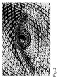
- Illustrative intaglio-printed patterns are shown in Figures 1 and 2 , which intaglio-printed patterns are analogous to those found on most intaglio-printed banknotes.
- Figure 1 is an enlarged view of an eye portion of a portrait that can be found in International application No. WO 03/103962 A1
- Figure 2 is an enlarged view of an eye portion of another portrait according to the teaching of International application No. WO 2007/119203 A1 wherein typical curvilinear intaglio-printed patterns are interlaced with micro-letters that are dimensionally modulated to produce variations in tones.
- These intaglio-printed patterns are typically formed of a complex arrangement of dimensionally modulated curvilinear elements that produce the desired halftones of the pictorial representation that one wishes to create on the security paper.
- the curvilinear elements typically have a line width of the order of 10 ⁇ m and more.
- the pixel-by-pixel engraving method can either be put into practice to engrave a precursor of an intaglio printing plate, such as a polymer plate, which precursor is then used to produce any number of identical printing plates by a galvanic replication process, or to directly engrave a metallic plate that is ultimately used as the intaglio printing plate, typically after chroming of the surface thereof.
- the engraving process is carried out by mounting the laser-engravable printing medium on the circumference of a rotating cylinder and moving the laser engraving device in a direction parallel to the axis of the cylinder.
- the laser engraving of polymer precursors of intaglio printing plates is advantageous over the direct laser engraving of printing plates in that engraving of a polymer precursor can be performed in a single pass and with a high engraving quality. Engraving of polymer precursors is accordingly particularly suited to the manufacture of high quality, high resolution intaglio printing plates for the production of banknotes.
- Direct laser engraving of intaglio printing plates however has an advantage in terms of environmental requirements in that it enables to circumvent the galvanic process which makes use of environmentally unfriendly chemical agents.
- a general aim of the invention is therefore to provide an improved method and system of manufacturing intaglio printing plates for the production of security papers, wherein a laser beam is used to engrave intaglio printing patterns directly into the surface of a laser-engravable metallic printing plate medium.
- a further aim of the invention is to provide such a method and system that improve the ability to shape the engraving profile of the intaglio printing patterns that one desires to engrave directly into the printing plate surface.
- Still another aim of the invention is to provide such a method and system that enables to limit the formation of melted residues and facilitates the removal and cleaning thereof, while guaranteeing a high quality of engraving.
- Yet another aim of the invention is to provide a solution that enables as much as possible to avoid resorting to the use of aggressive cleaning processes to remove the melted residues of the laser engraving process from the surface of the printing plate, which aggressive cleaning processes could negatively affect engraving uniformity and quality.
- a method of manufacturing intaglio printing plates for the production of security papers wherein a laser beam is used to engrave intaglio printing patterns directly into the surface of a laser-engravable metallic printing plate medium, wherein laser engraving of the metallic printing plate medium is carried out layer by layer in several individual engraving steps performed one after the other in register so that said intaglio printing patterns are gradually engraved into the surface of the metallic printing plate medium up to desired engraving depths, the surface of the engraved metallic printing plate medium being cleaned from residues of the laser engraving process following and between each individual engraving step.
- a direct laser engraving system for carrying out the above method, namely a laser engraving system comprising a support element for mounting the laser-engravable metallic printing plate medium, a laser engraving unit producing a laser beam that is directed towards the surface of the metallic printing plate medium for engraving the surface of the metallic printing plate medium layer by layer in several individual engraving steps and a cleaning unit for cleaning the surface of the engraved metallic printing plate medium and removing residues therefrom following and between each individual engraving step.
- the metallic printing plate medium is made of or comprises an outer layer made of nickel, steel, brass, zinc, chrome or alloys thereof. Furthermore, the angle of incidence of the laser beam with respect to the surface of the metallic printing plate medium remains constant throughout the engraving process.
- the engraving process is subdivided into a plurality of individual engraving steps which each involve removal of a limited quantity of material from the printing plate medium and accordingly limit the formation of residues. Furthermore, the surface of the engraved printing plate medium is cleaned following and between each individual engraving step such that the residues are removed before the next engraving step is performed, which ultimately improves engraving quality.
- each individual engraving step results in a selective removal of a layer of material from the printing plate medium the thickness of which does not exceed a pre-selected maximum value.
- This preselected maximum value is preferably of between 10 to 15 ⁇ m.
- cleaning of the surface of the engraved printing plate medium following and between each individual engraving step is performed mechanically, advantageously by means of a rotating brush that is moved over the surface of the engraved printing plate medium following and between each individual engraving step
- the printing plate medium is mounted onto the circumference of a support cylinder which is rotated in front of a movable laser engraving unit producing a laser beam that is directed towards the surface of the printing plate medium, which laser engraving unit is movable parallel to the axis of rotation of the support cylinder.
- the angle of incidence of the laser beam with respect to the surface of the printing plate medium being engraved is kept constant, thereby guaranteeing perfect engraving uniformity throughout the engraving process.
- a laser engraving unit producing a laser beam that is directed towards the surface of the printing plate medium is moved during each individual engraving step from a start position to an end position over the surface of the printing plate medium, and cleaning of the surface of the engraved printing plate medium is performed while the laser engraving unit, which is inoperative, is moved back from the end position to the start position.
- the laser engraving unit is moved during each individual engraving step from a start position to an end position step by step along the axis of rotation of the support cylinder so as to process successive annular portions of the surface of the printing plate medium, and cleaning of the surface of the engraved printing plate medium is performed while the laser engraving unit, which is inoperative, is moved back from the end position to the start position.
- engraving of the surface of the printing plate medium is first performed by starting with the deepest intaglio printing patterns and gradually adding shallower intaglio printing patterns during subsequent engraving steps.
- This advantageously enables to preserve the shallower and finer intaglio printing patterns up to the final engraving steps, which shallower and finer intaglio printing patterns are more sensitive to the cleaning operations.
- intaglio printing designs or “intaglio printing patterns” shall be understood as referring to designs and patterns produced by engraving and which consist of an arrangement of multiple curvilinear elements of varying line width and engraving depth.
- Such intaglio printing designs and patterns produce characteristic printed designs and patterns on the printed product which are readily recognizable and are found on most security papers. Examples of such intaglio-printed designs and patterns are illustrated in Figures 1 and 2 , which have already been discussed, as well as in Figure 3 which is illustrative of an exemplary intaglio design that can be engraved in the form of corresponding intaglio printing patterns into an intaglio printing plate by direct laser engraving according to the invention. These illustrations are obviously purely illustrative and shall not be considered as limiting the scope of the present invention.
- Intaglio printing designs and patterns produced according to the invention shall be distinguished from the designs and patterns used in the context of gravure printing (or rotogravure) where these merely consist of arrays of multiple cells of varying width and/or depth that are engraved into the surface of a cylinder, which cells are separated by cell walls.
- Gravure printing makes use of low viscosity inks that are allowed to flood above the cell walls so that the individual cells are no longer visible in the impression.
- the cells in gravure printing can typically be up to 50 ⁇ m deep (the cell depth being generally between 10 to 30 ⁇ m) and gravure printing does not produce any noticeable relief on the printed end-product.
- intaglio printing is based on the use of engraved printing plates having intaglio printing patterns taking the shape of curvilinear patterns the depth of at least part of which typically exceeds 50 ⁇ m.
- These intaglio printing patterns are furthermore inked with high viscosity inks and printing is carried out under high printing pressures, resulting in a characteristic embossing on the printed end-product.
- FIG 3 illustrates an exemplary intaglio design, designated globally by reference numeral 12, of a duty stamp or banderol that can be produced by direct laser engraving according to the invention.
- This intaglio design 12 consists of multiple design elements 12a to 12g, including for instance a so-called latent image 12a, texts or like alphanumerical indications in varying sizes 12b, 12c, 12d, large surface patterns 12e with ink retaining structures (not illustrated), logos 12f, and guilloche patterns 12g. Any other patterns or combination thereof could be envisaged, including patterns similar to those found in typical intaglio portraits as depicted in Figures 1 and 2 .
- the various design elements 12a to 12g of the intaglio-printed pattern of Figure 3 might be produced by means of a suitable design software, such as the software ONE® marketed by the present Applicant.
- the engraving profile of each design element 12a to 12g might be defined individually according to parameters selected by the designer to create a so-called original depth-map as discussed in International application No. WO 03/103962 A1 .
- This original depth-map is then replicated digitally as many time as required to form a master depth-map of the intaglio printing plate to engrave.
- a partial view of the surface of an intaglio printing plate 1 which was engraved on the basis of the intaglio design of Figure 3 is shown in the greyscale photograph of Figure 4 .
- the greyscale photograph of Figure 4 actually shows the mirrored image of the engraved intaglio printing plate 1, it being understood that the intaglio printing patterns that are engraved into the printing plate 1 mirror the intaglio design shown in Figure 3 .
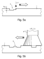
- Figure 5a schematically illustrates a printing plate medium 1 in the process of being engraved by a laser beam 2 to form engravings 3 in the surface thereof.
- the hatched area in Figure 5a is indicative of the material that is being removed by the laser beam 2.
- the dimensions of the engravings 3 have been exaggerated for the purpose of illustration.
- at least part of the intaglio printing patterns 3 can be engraved to a depth of approximately 80 ⁇ m. It shall be understood that the depth of the engravings can be as high as 150 (or eventually more), while a typical line width ranges from approximately 10 to 500 ⁇ m.
- Engraving is preferably performed pixel-by-pixel based on three-dimensional pixel data of an engraving depth-map of the desired intaglio printing patterns as discussed in International application No.
- the printing plate medium 1 is made of or comprises an outer layer made of a metal such as nickel, steel, brass, zinc, chrome or alloys thereof, which materials are all commonly used in the art.
- the printing plate medium 1 is engraved in several individual engraving steps ( Figure 5a illustrates a first one of a series of individual engraving steps) performed one after the other in register so that the intaglio printing patterns are gradually engraved layer by layer into the surface of the printing plate medium 1 up to desired engraving depths.
- each individual engraving step results in a selective removal of a layer of material from the printing plate medium 1 the thickness of which does not exceed a pre-selected maximum value ⁇ MAX .
- This maximum value ⁇ MAX is preferably of between 10 to 15 ⁇ m.
- the surface of the engraved printing plate medium 1 is cleaned following and between each individual engraving step, i.e. after removal of each layer. Cleaning of the surface of the printing plate medium 1 can conveniently be performed mechanically (i.e. without resorting to the use of aggressive cleaning processes). Such cleaning can advantageously be performed by means of a rotating brush 9 that is moved over the surface of the engraved printing plate medium 1.
- the printing plate medium 1 can advantageously be mounted onto the circumference of a support cylinder which is rotated in front of a movable laser engraving unit producing a laser beam that is directed towards the surface of the printing plate medium 1, which laser engraving unit is movable parallel to the axis of rotation of the support cylinder.
- each individual engraving step can conveniently be performed while the laser engraving unit is moved from a start position to an end position step by step along the axis of the support cylinder so as to process successive annular portions of the surface of the printing plate medium and cleaning of the surface of the printing plate medium 1 can be performed while the laser engraving unit, which is inoperative, is moved back from the end position to the start position.
- the angle of incidence of the laser beam 2 with respect to the surface of the printing plate medium 1 being engraved is kept constant, thereby guaranteeing perfect engraving uniformity throughout the engraving process.
- Figure 6 illustrates a possible sequence wherein first and second intaglio printing patterns, respectively designated by reference numerals 3.1 and 3.2 are gradually formed layer after layer.
- a first intaglio printing pattern 3.1 is for instance engraved in three steps by forming a first partial engraving during a first engraving step, deepening the engraving to a second partial engraving during a second engraving step, and ultimately to the final intaglio printing pattern 3.1 during a third engraving step.
- a shallower intaglio printing pattern 3.2 is similarly engraved in two steps which are performed simultaneously with the first and second partial engravings of the first intaglio printing pattern 3.1, a partial engraving being engraved during the first step and subsequently deepened to the final intaglio printing pattern 3.2 during the second engraving step.
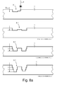
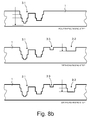
- the hatched areas in Figure 6 are again illustrative of the material that is being removed by the laser beam 2 during each engraving step (the same applies to Figure 7 and Figures 8a and 8b which are discussed hereinafter). It shall furthermore be understood that the surface of the printing plate medium 1 is cleaned from residues following and between each individual engraving step.
- Figure 7 illustrates another possible sequence wherein layer-by-layer engraving of the surface of the printing plate medium 1 is first performed by starting with the deepest intaglio printing patterns, e.g. intaglio printing pattern 3.1, and gradually adding shallower intaglio printing patterns, e.g. intaglio printing pattern 3.2 followed by intaglio printing pattern 3.3, during subsequent engraving steps.
- shallower intaglio printing patterns e.g. intaglio printing pattern 3.2 followed by intaglio printing pattern 3.3
- first engraving step only intaglio printing pattern 3.1 is partially engraved.
- this intaglio printing pattern 3.1 is deepened, while simultaneously forming a partial engraving of intaglio printing pattern 3.2.
- intaglio printing patterns 3.1 and 3.2 are further deepened, while a third shallower intaglio printing pattern 3.3 is formed in the surface of the printing plate medium 1.
- focusing of the laser beam 2 needs to be adjusted in this case during the second and third engraving steps as material is removed at different levels of the printing plate medium 1. This can be performed using an adequate system for adjusting focusing of the laser beam 2 during the engraving steps (such adjustment of the focus of the laser beam 2 would not be necessary during the first engraving step).
- Figures 8a and 8b for instance illustrate a case wherein intaglio printing pattern 3.1 is formed during a first engraving phase and intaglio printing patterns 3.2 and 3.3 are formed during a subsequent second engraving phase. More precisely, Figures 8a and 8b show that the first, second, third and fourth engraving steps (which first to fourth engraving steps correspond to a first engraving phase) are carried out to form intaglio printing pattern 3.1, while the shallower intaglio printing patterns 3.2 and 3.3 are formed simultaneously during the fifth and sixth engraving steps (which fifth and sixth engraving steps correspond to a second engraving phase). More than two engraving phases can obviously be envisaged.
- the focus of the laser beam 2 does not need to be adjusted during each engraving step, but rather merely from one step to the next as in the case of the sequence of engraving steps of Figure 6 .
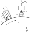
- Figure 9 is a schematic partial side view of a laser engraving system to carry out the method of the invention.
- the printing plate medium 1 is preferably mounted on the circumference of a support cylinder 5 (see also Figure 10 ) which is rotated in front of a movable engraving unit 4 producing a laser beam 2 that is directed towards the surface of the printing plate medium 1, which laser engraving unit 4 is movable parallel to the axis of rotation O of the support cylinder 5.
- the laser engraving unit 4 can be any type of suitable laser engraving unit, for instance a Ytterbium fiber laser unit.
- the laser can conveniently be supplied from a laser source (not illustrated) to a laser head of the unit 4 via an optical fibre cable 40.
- the laser engraving unit 4 is mounted on a frame (not illustrated in Figure 10 ) that is movable parallel to the axis of rotation O of the cylinder 5 between a start position (illustrated on the left-hand side in Figure 10 ) and an end position, designated by reference numeral 4* (on the right-hand side in Figure 10 ).
- the laser engraving unit 4 is movable during each individual engraving step from the start position to the end position (e.g. from left to right in Figure 10 ) step by step along the axis of rotation O of the support cylinder 5 so as to process successive annular portions of the surface of the printing plate medium 1.
- a cleaning unit designated globally by reference numeral 6, is preferably mounted by means of a supporting arm (not shown) on the same frame as the laser engraving unit 4 so as to move together with this latter.
- the supporting arm is designed to enable movement of the cleaning unit 6 between a working position (as illustrated in Figure 9 ) where the cleaning unit 6 is brought into contact with the surface of the printing plate medium 1 carried on the support cylinder 5 and a retracted, inoperative position (not illustrated) where the cleaning unit 6 is moved away from the surface of the printing plate medium 1.
- the cleaning unit 6 is preferably operative while the laser engraving unit 4, which is inoperative, is moved back from the end position to the start position, e.g from right to left in Figure 10 .
- the cleaning unit 6 preferably comprises a rotating brush 9 for brushing the surface of the printing plate medium 1.
- the cleaning unit 6 may advantageously be further provided with an aspiration head 10 for aspirating the residues that are removed from the surface of the printing plate medium 1.
- the rotating brush 9 is located within the aspiration head 10 so that residues can be conveniently aspirated from all areas surrounding the rotating brush 9.
- a rotational speed of the brush 9, pressure between the brush 9 and the surface of the printing plate medium 1 and/or displacement speed of the cleaning unit 6 parallel to the axis of rotation O of the support cylinder 5 is/are advantageously adjustable so as to ensure optimum cleaning efficiency.
- the printing plate medium 1 is advantageously engraved while being held on the support cylinder 5 in the same way as it would be held on the circumference of a plate cylinder of an intaglio printing press.
- This ensures that the engraving profile of the engravings remains substantially unchanged when the engraved printing plate medium 1 is ultimately installed in an intaglio printing press, which is an advantageous over a solution as disclosed in International application No. WO 97/48555 A1 , European patent application No. EP 1 334 822 A2 , International application No. WO 2006/045128 A1 or Deinhammer2006 where the printing plate medium 1 is engraved while being held flat.
- intaglio printing presses are disclosed in European patent applications Nos.
Landscapes
- Engineering & Computer Science (AREA)
- Physics & Mathematics (AREA)
- Optics & Photonics (AREA)
- Plasma & Fusion (AREA)
- Manufacturing & Machinery (AREA)
- Mechanical Engineering (AREA)
- Thermal Sciences (AREA)
- Manufacture Or Reproduction Of Printing Formes (AREA)
- Printing Plates And Materials Therefor (AREA)
- Laser Beam Processing (AREA)
Abstract
Description
- The present invention generally relates to the field of intaglio printing as applied for the production of security papers, including banknotes, duty stamps, banderols or labels, identification or travel documents, etc.
- The present invention more precisely relates to a method and system of manufacturing intaglio printing plates for intaglio printing of sheets or webs of security papers, which method and system are based on the direct laser engraving of a metallic printing plate medium.
- The manufacturing of intaglio printing plates for the production of securities by direct laser engraving is already know in the art.
- International application No.
WO 97/48555 A1 - European patent application No.
EP 1 334 822 A2 - International application No.
WO 2006/045128 A1 discloses a direct laser engraving system for the production of intaglio printing plates that follows a similar approach to the one described in the above-mentioned European patent application No.EP 1 334 822 A2WO 2006/045128 A1 , this implies performing a calibration operation at regular intervals which is cumbersome and time-consuming. - A further disadvantage of the direct laser engraving system of International application No.
WO 2006/045128 A1 again resides in the fact that the angle of incidence of the laser beam with respect to the printing plate surface varies according to the position of the laser beam with respect to the locations of the engraving area being treated, which potentially leads to engraving non-uniformities which shall be avoided. - Yet another disadvantage of this direct laser engraving system (which also characterizes the approach disclosed in International application No.
WO 97/48555 A1 - Further discussion regarding the direct laser engraving of intaglio printing plates might further be found in International application No.
WO 2005/002869 A1 and the related article of Messrs. Harald Deinhammer, Franz Loos, Daniel Schwarzbach and Peter Fajmann entitled "Direct Laser Engraving of Intaglio Printing Plates", Proceedings of SPIE, Vol. 5310, 2004, pp. 184-193 (hereinafter referred to as Deinhammer2004). According to International application No.WO 2005/002869 A1 , the printing plate, which is made of or has an outer layer consisting of brass or an alloy thereof, is engraved directly by laser and, once fully engraved, is subjected to a cleaning process to remove the melted residues of the laser engraving process, which cleaning process involves a chemical treatment in a chemical bath of acidic solution, before being ultimately polished and chromed. A dry-ice pre-cleaning of the surface of the engraved printing plate by spraying of solid carbon-dioxide pellets may be performed prior to the chemical treatment of the engraved plate (see again Deinhammer2006). The proposed chemical post-engraving treatment of the engraved printing plate, as well as the dry-ice pre-cleaning, is rather aggressive and can lead to a degradation of the desired intaglio engravings if it is not controlled and carried out properly. The post-engraving processing with dry-ice pre-cleaning and treatment with acidic solution are furthermore prejudicial as they could lead to engraving non-uniformities and lack of repeatability, namely differences between two intaglio printing plates produced from a same design. - International application No.
WO 03/103962 A1 - A substantial advantage of this approach resides in the fact that the various design elements forming the whole intaglio design to be engraved in the printing plate are not engraved individually, but rather all at once pixel by pixel. Furthermore, and in contrast to the above-mentioned approaches, the engraving times are independent of the complexity of the intaglio design and depend only on the maximum depth of the design to be engraved. This pixel by pixel approach further translates into greater flexibility and control regarding the engraving profile and the shape thereof.
- The engraving method disclosed in International application No.
WO 03/103962 A1 WO 2005/090090 A1 andWO 2007/119203 A1 , also in the name of the present Applicant. The pixel-by-pixel engraving principle disclosed inWO 03/103962 A1 WO 2007/119203 A1 which exhibit a high complexity and density of elements, and this with reasonably low engraving times. Illustrative intaglio-printed patterns are shown inFigures 1 and2 , which intaglio-printed patterns are analogous to those found on most intaglio-printed banknotes.Figure 1 is an enlarged view of an eye portion of a portrait that can be found in International application No.WO 03/103962 A1 Figure 2 is an enlarged view of an eye portion of another portrait according to the teaching of International application No.WO 2007/119203 A1 wherein typical curvilinear intaglio-printed patterns are interlaced with micro-letters that are dimensionally modulated to produce variations in tones. These intaglio-printed patterns are typically formed of a complex arrangement of dimensionally modulated curvilinear elements that produce the desired halftones of the pictorial representation that one wishes to create on the security paper. The curvilinear elements typically have a line width of the order of 10 µm and more. - As discussed in International application No.
WO 03/103962 A1 - The laser engraving of polymer precursors of intaglio printing plates as taught in International application No.
WO 03/103962 A1 - The laser engraving of polymer precursors of intaglio printing plates is advantageous over the direct laser engraving of printing plates in that engraving of a polymer precursor can be performed in a single pass and with a high engraving quality. Engraving of polymer precursors is accordingly particularly suited to the manufacture of high quality, high resolution intaglio printing plates for the production of banknotes.
- Another advantage of the laser engraving of polymer precursors of intaglio printing plates resides in the fact that such precursors, once engraved, can be used to produce a so-called "Alto" by a galvanic process, which Alto can be used to produce a master (or original) printing plate used to replicate multiple absolutely identical intaglio printing plates or as "master Alto" to directly produce such multiple absolutely identical intaglio printing plates. Since the galvanic process is a very stable and homogenous process, the likelihood that differences occur between multiple printing plates which have been replicated from a same master is almost inexistent. Furthermore, the same printing plate materials as conventionally used in the industry can be exploited without this bearing any impact on the actual work of the printer operating the printing press.
- Direct laser engraving of intaglio printing plates however has an advantage in terms of environmental requirements in that it enables to circumvent the galvanic process which makes use of environmentally unfriendly chemical agents.
- Tests carried out by the Applicant have demonstrated that the direct laser engraving of printing plate mediums, especially metallic mediums, leads to the formation of residues which need to be removed to ensure proper engraving and printing quality. The amount of residues is directly dependent on the depth of the engravings and therefore increases with engraving depth. These amounts of residues become particularly critical to remove as soon as one wishes to form relatively deep engravings in the printing plate medium, especially engravings having a depth exceeding 50 µm (and even more critically above 100 µm).
- While the particular choice of the printing plate material impacts on the formation of melted residues, such formation is unavoidable in the context of the direct laser engraving of intaglio printing plates and care should be taken to remove these residues while avoiding to degrade the quality of the desired engravings. This is again very critical when it comes to engraving deep intaglio printing patterns as substantial amounts of residues are produced that become difficult to remove.
- This constitutes one of the reasons why it is proposed in Deinhammer2006 to perform a pre-cleaning operation of the surface of the engraving printing plate by spraying dry-ice pellets of carbon dioxide at low temperature (of the order of - 80°C) on the surface of the plate and then to subject the pre-cleaned printing plate to a chemical treatment in an acidic solution. As already mentioned, such operations are potentially prejudicial as they could lead to engraving non-uniformities. These cleaning operations can furthermore only be carried out once the printing plate has been fully engraved.
- It has also been noticed that while the energy of the laser beam is well absorbed and converted into thermal energy in the first few micrometers of the material of the engraved printing plate medium, resulting in a local melting and evaporation of the material, the thermal energy is no longer directed and is spreading evenly in all direction into the material lower in the printing plate medium. As a result, higher laser energy do not only create deeper engravings, but also increased line widths (see again Deinhammer2004).
- There is therefore a need for an improved method and system for the manufacture of intaglio printing plates wherein a laser beam is used to engrave intaglio printing patterns directly into the surface of a laser-engravable metallic printing plate medium.
- A general aim of the invention is therefore to provide an improved method and system of manufacturing intaglio printing plates for the production of security papers, wherein a laser beam is used to engrave intaglio printing patterns directly into the surface of a laser-engravable metallic printing plate medium.
- A further aim of the invention is to provide such a method and system that improve the ability to shape the engraving profile of the intaglio printing patterns that one desires to engrave directly into the printing plate surface.
- Still another aim of the invention is to provide such a method and system that enables to limit the formation of melted residues and facilitates the removal and cleaning thereof, while guaranteeing a high quality of engraving.
- Yet another aim of the invention is to provide a solution that enables as much as possible to avoid resorting to the use of aggressive cleaning processes to remove the melted residues of the laser engraving process from the surface of the printing plate, which aggressive cleaning processes could negatively affect engraving uniformity and quality.
- These aims are achieved thanks to the solution defined in the claims.
- According to the invention, there is provided a method of manufacturing intaglio printing plates for the production of security papers, wherein a laser beam is used to engrave intaglio printing patterns directly into the surface of a laser-engravable metallic printing plate medium, wherein laser engraving of the metallic printing plate medium is carried out layer by layer in several individual engraving steps performed one after the other in register so that said intaglio printing patterns are gradually engraved into the surface of the metallic printing plate medium up to desired engraving depths, the surface of the engraved metallic printing plate medium being cleaned from residues of the laser engraving process following and between each individual engraving step.
- There is also provided a direct laser engraving system for carrying out the above method, namely a laser engraving system comprising a support element for mounting the laser-engravable metallic printing plate medium, a laser engraving unit producing a laser beam that is directed towards the surface of the metallic printing plate medium for engraving the surface of the metallic printing plate medium layer by layer in several individual engraving steps and a cleaning unit for cleaning the surface of the engraved metallic printing plate medium and removing residues therefrom following and between each individual engraving step.
- According to the invention, the metallic printing plate medium is made of or comprises an outer layer made of nickel, steel, brass, zinc, chrome or alloys thereof. Furthermore, the angle of incidence of the laser beam with respect to the surface of the metallic printing plate medium remains constant throughout the engraving process.
- Thanks to this solution, the engraving process is subdivided into a plurality of individual engraving steps which each involve removal of a limited quantity of material from the printing plate medium and accordingly limit the formation of residues. Furthermore, the surface of the engraved printing plate medium is cleaned following and between each individual engraving step such that the residues are removed before the next engraving step is performed, which ultimately improves engraving quality.
- According to one embodiment, each individual engraving step results in a selective removal of a layer of material from the printing plate medium the thickness of which does not exceed a pre-selected maximum value. This preselected maximum value is preferably of between 10 to 15 µm.
- According to another embodiment, cleaning of the surface of the engraved printing plate medium following and between each individual engraving step is performed mechanically, advantageously by means of a rotating brush that is moved over the surface of the engraved printing plate medium following and between each individual engraving step
- According to still another embodiment, the printing plate medium is mounted onto the circumference of a support cylinder which is rotated in front of a movable laser engraving unit producing a laser beam that is directed towards the surface of the printing plate medium, which laser engraving unit is movable parallel to the axis of rotation of the support cylinder.
- According to the invention, the angle of incidence of the laser beam with respect to the surface of the printing plate medium being engraved is kept constant, thereby guaranteeing perfect engraving uniformity throughout the engraving process.
- According to a further embodiment, a laser engraving unit producing a laser beam that is directed towards the surface of the printing plate medium is moved during each individual engraving step from a start position to an end position over the surface of the printing plate medium, and cleaning of the surface of the engraved printing plate medium is performed while the laser engraving unit, which is inoperative, is moved back from the end position to the start position.
- Advantageously, in the context of the embodiment wherein the printing plate medium is mounted onto the circumference of a support cylinder as mentioned above, the laser engraving unit is moved during each individual engraving step from a start position to an end position step by step along the axis of rotation of the support cylinder so as to process successive annular portions of the surface of the printing plate medium, and cleaning of the surface of the engraved printing plate medium is performed while the laser engraving unit, which is inoperative, is moved back from the end position to the start position.
- According to yet another embodiment, engraving of the surface of the printing plate medium is first performed by starting with the deepest intaglio printing patterns and gradually adding shallower intaglio printing patterns during subsequent engraving steps. This advantageously enables to preserve the shallower and finer intaglio printing patterns up to the final engraving steps, which shallower and finer intaglio printing patterns are more sensitive to the cleaning operations. This could be performed using an automatic focusing system to adjust focusing of the laser beam during individual engraving steps or by decomposing the engraving sequence in multiple engraving phases, each comprising one or more individual engraving steps, whereby only part of the desired intaglio printing patterns are engraved during each engraving phase.
- Further advantageous embodiments of the invention form the subject-matter of the dependent claims and are discussed below.
- Other features and advantages of the present invention will appear more clearly from reading the following detailed description of embodiments of the invention which are presented solely by way of non-restrictive examples and illustrated by the attached drawings in which:
-
Figure 1 is an enlarged view of an eye portion of a portrait realized by intaglio printing that can be found in International application No.WO 03/103962 A1 -
Figure 2 is an enlarged view of an eye portion of another portrait realized by intaglio printing according to the teaching of International application No.WO 2007/119203 A1 ; -
Figure 3 is an illustration of an exemplary intaglio design for a duty stamp or banderol, which intaglio design consists of multiple design elements that can be produced by direct laser engraving according to the invention ; -
Figure 4 is a greyscale photograph of a portion of an intaglio printing plate engraved according to the invention wherein multiple intaglio printing patterns as illustrated inFigure 3 have been engraved on the intaglio printing plate ; -
Figures 5a and 5b are two schematic illustrations of an individual engraving step and a thereafter following cleaning step according to the invention ; -
Figure 6 is a schematic illustration showing a possible sequence of individual engraving steps of an intaglio printing plate according to the invention ; -
Figure 7 is a schematic illustration showing another possible sequence of individual engraving steps of an intaglio printing plate according to the invention ; -
Figures 8a and8b are schematic illustrations showing another possible sequence of individual engraving steps of an intaglio printing plate according to the invention ; -
Figure 9 is a schematic side view of a laser engraving system to carry out the method of the invention ; and -
Figure 10 is a schematic perspective view of the laser engraving system ofFigure 9 where only part of the components thereof have been illustrated. - In the context of the present invention, "intaglio printing designs" or "intaglio printing patterns" shall be understood as referring to designs and patterns produced by engraving and which consist of an arrangement of multiple curvilinear elements of varying line width and engraving depth. Such intaglio printing designs and patterns produce characteristic printed designs and patterns on the printed product which are readily recognizable and are found on most security papers. Examples of such intaglio-printed designs and patterns are illustrated in
Figures 1 and2 , which have already been discussed, as well as inFigure 3 which is illustrative of an exemplary intaglio design that can be engraved in the form of corresponding intaglio printing patterns into an intaglio printing plate by direct laser engraving according to the invention. These illustrations are obviously purely illustrative and shall not be considered as limiting the scope of the present invention. - Intaglio printing designs and patterns produced according to the invention shall be distinguished from the designs and patterns used in the context of gravure printing (or rotogravure) where these merely consist of arrays of multiple cells of varying width and/or depth that are engraved into the surface of a cylinder, which cells are separated by cell walls. Gravure printing makes use of low viscosity inks that are allowed to flood above the cell walls so that the individual cells are no longer visible in the impression. The cells in gravure printing can typically be up to 50 µm deep (the cell depth being generally between 10 to 30 µm) and gravure printing does not produce any noticeable relief on the printed end-product. Details about gravure printing might be found in the "Handbook of Print Media" by Helmut Kipphan, Springer-Verlag, 2001, ISBN 3-540-67326-1 (see for instance chapter 1.3.2.2 on pages 48 to 53 and chapter 2.2 on pages 360 to 394).
- In contrast, intaglio printing, as applied for the production of security papers, is based on the use of engraved printing plates having intaglio printing patterns taking the shape of curvilinear patterns the depth of at least part of which typically exceeds 50 µm. These intaglio printing patterns are furthermore inked with high viscosity inks and printing is carried out under high printing pressures, resulting in a characteristic embossing on the printed end-product.
-
Figure 3 illustrates an exemplary intaglio design, designated globally byreference numeral 12, of a duty stamp or banderol that can be produced by direct laser engraving according to the invention. Thisintaglio design 12 consists ofmultiple design elements 12a to 12g, including for instance a so-calledlatent image 12a, texts or like alphanumerical indications in varyingsizes large surface patterns 12e with ink retaining structures (not illustrated),logos 12f, andguilloche patterns 12g. Any other patterns or combination thereof could be envisaged, including patterns similar to those found in typical intaglio portraits as depicted inFigures 1 and2 . - The
various design elements 12a to 12g of the intaglio-printed pattern ofFigure 3 might be produced by means of a suitable design software, such as the software ONE® marketed by the present Applicant. The engraving profile of eachdesign element 12a to 12g might be defined individually according to parameters selected by the designer to create a so-called original depth-map as discussed in International application No.WO 03/103962 A1 intaglio printing plate 1 which was engraved on the basis of the intaglio design ofFigure 3 is shown in the greyscale photograph ofFigure 4 . The greyscale photograph ofFigure 4 actually shows the mirrored image of the engravedintaglio printing plate 1, it being understood that the intaglio printing patterns that are engraved into theprinting plate 1 mirror the intaglio design shown inFigure 3 . - The basic principle of the method according to the invention will now be described in reference to
Figures 5a and 5b. Figure 5a schematically illustrates aprinting plate medium 1 in the process of being engraved by alaser beam 2 to formengravings 3 in the surface thereof. The hatched area inFigure 5a is indicative of the material that is being removed by thelaser beam 2. The dimensions of theengravings 3 have been exaggerated for the purpose of illustration. As an example, at least part of theintaglio printing patterns 3 can be engraved to a depth of approximately 80 µm. It shall be understood that the depth of the engravings can be as high as 150 (or eventually more), while a typical line width ranges from approximately 10 to 500 µm. Wider line widths or surfaces are possible under the provision that suitable ink retaining structures are formed in the engravings, which ink retaining structures are aimed at preventing the ink from being wiped off from the engraving by the wiping system of intaglio printing presses. - Engraving is preferably performed pixel-by-pixel based on three-dimensional pixel data of an engraving depth-map of the desired intaglio printing patterns as discussed in International application No.
-
WO 03/103962 A1 printing plate medium 1 is made of or comprises an outer layer made of a metal such as nickel, steel, brass, zinc, chrome or alloys thereof, which materials are all commonly used in the art. - According to the present invention, the
printing plate medium 1 is engraved in several individual engraving steps (Figure 5a illustrates a first one of a series of individual engraving steps) performed one after the other in register so that the intaglio printing patterns are gradually engraved layer by layer into the surface of theprinting plate medium 1 up to desired engraving depths. Preferably, each individual engraving step results in a selective removal of a layer of material from theprinting plate medium 1 the thickness of which does not exceed a pre-selected maximum value ΔMAX. This maximum value ΔMAX is preferably of between 10 to 15 µm. - As illustrated schematically by
Figure 5b , the surface of the engravedprinting plate medium 1 is cleaned following and between each individual engraving step, i.e. after removal of each layer. Cleaning of the surface of theprinting plate medium 1 can conveniently be performed mechanically (i.e. without resorting to the use of aggressive cleaning processes). Such cleaning can advantageously be performed by means of arotating brush 9 that is moved over the surface of the engravedprinting plate medium 1. - As will be appreciated hereinafter, the
printing plate medium 1 can advantageously be mounted onto the circumference of a support cylinder which is rotated in front of a movable laser engraving unit producing a laser beam that is directed towards the surface of theprinting plate medium 1, which laser engraving unit is movable parallel to the axis of rotation of the support cylinder. In this context, each individual engraving step can conveniently be performed while the laser engraving unit is moved from a start position to an end position step by step along the axis of the support cylinder so as to process successive annular portions of the surface of the printing plate medium and cleaning of the surface of theprinting plate medium 1 can be performed while the laser engraving unit, which is inoperative, is moved back from the end position to the start position. - According to the invention, the angle of incidence of the
laser beam 2 with respect to the surface of theprinting plate medium 1 being engraved is kept constant, thereby guaranteeing perfect engraving uniformity throughout the engraving process. - Different sequences of individual engraving steps might be envisaged in the context of the present invention.
Figure 6 illustrates a possible sequence wherein first and second intaglio printing patterns, respectively designated by reference numerals 3.1 and 3.2 are gradually formed layer after layer. A first intaglio printing pattern 3.1 is for instance engraved in three steps by forming a first partial engraving during a first engraving step, deepening the engraving to a second partial engraving during a second engraving step, and ultimately to the final intaglio printing pattern 3.1 during a third engraving step. A shallower intaglio printing pattern 3.2 is similarly engraved in two steps which are performed simultaneously with the first and second partial engravings of the first intaglio printing pattern 3.1, a partial engraving being engraved during the first step and subsequently deepened to the final intaglio printing pattern 3.2 during the second engraving step. The hatched areas inFigure 6 are again illustrative of the material that is being removed by thelaser beam 2 during each engraving step (the same applies toFigure 7 andFigures 8a and8b which are discussed hereinafter). It shall furthermore be understood that the surface of theprinting plate medium 1 is cleaned from residues following and between each individual engraving step. -
Figure 7 illustrates another possible sequence wherein layer-by-layer engraving of the surface of theprinting plate medium 1 is first performed by starting with the deepest intaglio printing patterns, e.g. intaglio printing pattern 3.1, and gradually adding shallower intaglio printing patterns, e.g. intaglio printing pattern 3.2 followed by intaglio printing pattern 3.3, during subsequent engraving steps. For instance, during the first engraving step, only intaglio printing pattern 3.1 is partially engraved. During the second step, this intaglio printing pattern 3.1 is deepened, while simultaneously forming a partial engraving of intaglio printing pattern 3.2. During the third step, intaglio printing patterns 3.1 and 3.2 are further deepened, while a third shallower intaglio printing pattern 3.3 is formed in the surface of theprinting plate medium 1. - As is apparent in
Figure 7 , focusing of thelaser beam 2 needs to be adjusted in this case during the second and third engraving steps as material is removed at different levels of theprinting plate medium 1. This can be performed using an adequate system for adjusting focusing of thelaser beam 2 during the engraving steps (such adjustment of the focus of thelaser beam 2 would not be necessary during the first engraving step). - Alternatively, as illustrated in
Figures 8a and8b , one may decompose the layer-by-layer engraving sequence into a plurality of engraving phases, each comprising one or more individual engraving steps, whereby only part of the desired intaglio printing patterns are engraved during each engraving phase. -
Figures 8a and8b for instance illustrate a case wherein intaglio printing pattern 3.1 is formed during a first engraving phase and intaglio printing patterns 3.2 and 3.3 are formed during a subsequent second engraving phase. More precisely,Figures 8a and8b show that the first, second, third and fourth engraving steps (which first to fourth engraving steps correspond to a first engraving phase) are carried out to form intaglio printing pattern 3.1, while the shallower intaglio printing patterns 3.2 and 3.3 are formed simultaneously during the fifth and sixth engraving steps (which fifth and sixth engraving steps correspond to a second engraving phase). More than two engraving phases can obviously be envisaged. - In contrast to the previous sequence of engraving steps discussed in reference to
Figure 7 , the focus of thelaser beam 2 does not need to be adjusted during each engraving step, but rather merely from one step to the next as in the case of the sequence of engraving steps ofFigure 6 . - The sequences of engraving steps discussed hereinabove in reference to
Figure 7 andFigures 8a and8b might be advantageous in that the shallower and finer intaglio printing patterns are formed during the ultimate stages of the engraving process and are preserved from the repeated cleaning operations. - The sequences of engraving steps discussed hereinabove in reference to
Figures 6 ,7 ,8a and8b are only illustrative of possible engraving sequences. Other sequences of engraving steps might be envisaged. -
Figure 9 is a schematic partial side view of a laser engraving system to carry out the method of the invention. As already mentioned, theprinting plate medium 1 is preferably mounted on the circumference of a support cylinder 5 (see alsoFigure 10 ) which is rotated in front of amovable engraving unit 4 producing alaser beam 2 that is directed towards the surface of theprinting plate medium 1, whichlaser engraving unit 4 is movable parallel to the axis of rotation O of thesupport cylinder 5. - The
laser engraving unit 4 can be any type of suitable laser engraving unit, for instance a Ytterbium fiber laser unit. The laser can conveniently be supplied from a laser source (not illustrated) to a laser head of theunit 4 via anoptical fibre cable 40. Thelaser engraving unit 4 is mounted on a frame (not illustrated inFigure 10 ) that is movable parallel to the axis of rotation O of thecylinder 5 between a start position (illustrated on the left-hand side inFigure 10 ) and an end position, designated byreference numeral 4* (on the right-hand side inFigure 10 ). - The
laser engraving unit 4 is movable during each individual engraving step from the start position to the end position (e.g. from left to right inFigure 10 ) step by step along the axis of rotation O of thesupport cylinder 5 so as to process successive annular portions of the surface of theprinting plate medium 1. - A cleaning unit, designated globally by
reference numeral 6, is preferably mounted by means of a supporting arm (not shown) on the same frame as thelaser engraving unit 4 so as to move together with this latter. The supporting arm is designed to enable movement of thecleaning unit 6 between a working position (as illustrated inFigure 9 ) where thecleaning unit 6 is brought into contact with the surface of theprinting plate medium 1 carried on thesupport cylinder 5 and a retracted, inoperative position (not illustrated) where thecleaning unit 6 is moved away from the surface of theprinting plate medium 1. Thecleaning unit 6 is preferably operative while thelaser engraving unit 4, which is inoperative, is moved back from the end position to the start position, e.g from right to left inFigure 10 . Other arrangements for mounting of thecleaning unit 6 can however be envisaged, including arrangements wherein thecleaning unit 6 and thelaser engraving unit 4 are mounted on separate frames and/or arrangements wherein thecleaning unit 6 is retractable, for instance through rotation of thecleaning unit 6 towards and away from the surface of theprinting plate medium 1 carried by thesupport cylinder 5. - The
cleaning unit 6 preferably comprises arotating brush 9 for brushing the surface of theprinting plate medium 1. Thecleaning unit 6 may advantageously be further provided with anaspiration head 10 for aspirating the residues that are removed from the surface of theprinting plate medium 1. In this example, the rotatingbrush 9 is located within theaspiration head 10 so that residues can be conveniently aspirated from all areas surrounding the rotatingbrush 9. - A rotational speed of the
brush 9, pressure between thebrush 9 and the surface of theprinting plate medium 1 and/or displacement speed of thecleaning unit 6 parallel to the axis of rotation O of thesupport cylinder 5 is/are advantageously adjustable so as to ensure optimum cleaning efficiency. - In the system of
Figures 9 and10 , theprinting plate medium 1 is advantageously engraved while being held on thesupport cylinder 5 in the same way as it would be held on the circumference of a plate cylinder of an intaglio printing press. This ensures that the engraving profile of the engravings remains substantially unchanged when the engravedprinting plate medium 1 is ultimately installed in an intaglio printing press, which is an advantageous over a solution as disclosed in International application No.WO 97/48555 A1 EP 1 334 822 A2WO 2006/045128 A1 or Deinhammer2006 where theprinting plate medium 1 is engraved while being held flat. For the sake of completeness, intaglio printing presses are disclosed in European patent applications Nos.EP 0 091 709 A1 ,EP 0 351 366 A2 ,EP 0 406 157 A1 ,EP 0 415 881 A1 ,EP 0 563 007 A1 ,EP 0 683 123 A1 ,EP 0 873 866 A1 ,EP 1 400 353 A1EP 1 442 878 A1EP 1 445 098 A1EP 1 448 393 A1WO 03/047862 A1 EP 1 580 015 A1EP 1 602 482 A1EP 1 602 483 A1EP 1 622 769 A1WO 2004/101282 A1 ) andEP 1 704 052 A1WO 2005/077656 A1 ),, all in the name of the present Applicant. - Various modifications and/or improvements may be made to the above-described embodiments without departing from the scope of the invention as defined by the annexed claims. For instance, while the above-discussed embodiment of the laser engraving system comprises a rotatable support cylinder on the circumference of which the laser-engravable printing plate medium is mounted, the invention is equally applicable to engraving systems making use of a flat x-y table.
Claims (16)
- A method of manufacturing intaglio printing plates for the production of security papers, wherein a laser beam (2) is used to engrave intaglio printing patterns (3, 3.1, 3.2, 3.3) directly into the surface of a laser-engravable metallic printing plate medium (1), wherein laser engraving of the metallic printing plate medium (1) is carried out layer by layer in several individual engraving steps performed one after the other in register so that said intaglio printing patterns are gradually engraved into the surface of the metallic printing plate medium (1) up to desired engraving depths,
wherein the surface of the engraved metallic printing plate medium (1) is cleaned from residues of the laser engraving process following and between each individual engraving step,
wherein the metallic printing plate medium (1) is made of or comprises an outer layer made of nickel, steel, brass, zinc, chrome or alloys thereof,
and wherein an angle of incidence of the laser beam (2) with respect to the surface of the metallic printing plate medium (1) remains constant throughout the engraving process. - The method according to claim 1, wherein each individual engraving step results in a selective removal of a layer of material from the metallic printing plate medium (1) the thickness of which does not exceed a preselected maximum value, preferably of between 10 to 15 µm.
- The method according to claim 1 or 2, wherein at least part of said intaglio printing patterns are engraved to a depth of at least 80 µm.
- The method according to any one of the preceding claims, wherein cleaning of the surface of the engraved metallic printing plate medium (1) following and between each individual engraving step is performed mechanically,
and wherein cleaning of the surface of the engraved metallic printing plate medium (1) following and between each individual engraving step is preferably performed by means of a rotating brush (9) that is moved over the surface of the engraved metallic printing plate medium (1) following and between each individual engraving step.. - The method according to any one of the preceding claims, wherein each engraving step involves a pixel-by-pixel engraving of the metallic printing plate medium (1) based on three-dimensional pixel data of an engraving depth-map of said intaglio printing patterns.
- The method according to any one of the preceding claims, wherein, a laser engraving unit (4) producing a laser beam (2) that is directed towards the surface of the metallic printing plate medium (1) is moved during each individual engraving step from a start position to an end position over the surface of the metallic printing plate medium (1), and wherein cleaning of the surface of the engraved metallic printing plate medium (1) is performed while the laser engraving unit (4), which is inoperative, is moved back from the end position to the start position.
- The method according to any one of the preceding claims, wherein said metallic printing plate medium (1) is mounted onto the circumference of a support cylinder (5) which is rotated in front of a movable laser engraving unit (4) producing a laser beam (2) that is directed towards the surface of the metallic printing plate medium (1), which laser engraving unit (4) is movable parallel to the axis of rotation (O) of the support cylinder (5).
- The method according to claim 7, wherein the laser engraving unit (4) is moved during each individual engraving step from a start position to an end position step by step along the axis of rotation (O) of the support cylinder (5) so as to process successive annular portions of the surface of the metallic printing plate medium (1), and wherein cleaning of the surface of the engraved metallic printing plate medium (1) is performed while the laser engraving unit (4), which is inoperative, is moved back from the end position to the start position.
- The method according to any one of the preceding claims, wherein engraving of the surface of the metallic printing plate medium (1) is first performed by starting with the deepest intaglio printing patterns and gradually adding shallower intaglio printing patterns during subsequent engraving steps.
- The method according to claim 9, wherein a focus of said laser beam (2) is adjusted during at least one of said individual engraving steps.
- The method according to claim 9, wherein a focus of said laser beam (2) is not adjusted during said individual engraving steps and wherein engraving of the surface of the metallic printing plate medium (1) is decomposed into a plurality of engraving phases, each comprising one or more individual engraving steps, whereby only part of the desired intaglio printing patterns (3.1, 3.2, 3.3) are engraved during each engraving phase.
- A laser engraving system for carrying out the method according to any one of the preceding claims, comprising a support element (5) for mounting said laser-engravable metallic printing plate medium (1), a laser engraving unit (4) producing a laser beam (2) that is directed towards the surface of the metallic printing plate medium (1) for engraving the surface of the metallic printing plate medium (1) layer by layer in several individual engraving steps and a cleaning unit (6) for cleaning the surface of the engraved metallic printing plate medium (1) and removing residues therefrom following and between each individual engraving step,
wherein the metallic printing plate medium (1) is made of or comprises an outer layer made of nickel, steel, brass, zinc, chrome or alloys thereof,
and wherein an angle of incidence of the laser beam (2) with respect to the surface of the metallic printing plate medium (1) remains constant throughout the engraving process. - The laser engraving system according to claim 12, wherein said metallic printing plate medium (1) is mounted onto the circumference of a support cylinder (5) acting as said support element, which support cylinder (5) is rotated in front of said laser engraving unit (4), which laser engraving unit (4) is movable parallel to the axis of rotation (O) of the support cylinder (5).
- The laser engraving system according to claim 13, wherein the laser engraving unit (4) is movable during each individual engraving step from a start position to an end position step by step along the axis of rotation (O) of the support cylinder (5) so as to process successive annular portions of the surface of the metallic printing plate medium (1), and wherein said cleaning unit (6) is operative while the laser engraving unit (4), which is inoperative, is moved back from the end position to the start position.
- The laser engraving system according to any one of claims 12 to 14, wherein said laser engraving unit (4) and said cleaning unit (6) are mounted on a common frame that is movable with respect to the surface of the metallic printing plate medium (1).
- The laser engraving system according to any one of claims 12 to 15, wherein said cleaning unit (6) comprises a rotatable brush (9) that can be brought into contact with the surface of the engraved metallic printing plate medium (1) to mechanically remove residues from the engraved metallic printing plate medium (1).
Priority Applications (1)
| Application Number | Priority Date | Filing Date | Title |
|---|---|---|---|
| EP14158764.2A EP2743025A3 (en) | 2008-05-16 | 2009-05-05 | Method and system of manufacturing intaglio printing plates for the production of security papers |
Applications Claiming Priority (3)
| Application Number | Priority Date | Filing Date | Title |
|---|---|---|---|
| EP08156392A EP2119527A1 (en) | 2008-05-16 | 2008-05-16 | Method and system for manufacturing intaglio printing plates for the production of security papers |
| EP09746196.6A EP2300192B1 (en) | 2008-05-16 | 2009-05-05 | Method and system for manufacturing intaglio printing plates for the production of security papers |
| EP14158764.2A EP2743025A3 (en) | 2008-05-16 | 2009-05-05 | Method and system of manufacturing intaglio printing plates for the production of security papers |
Related Parent Applications (1)
| Application Number | Title | Priority Date | Filing Date |
|---|---|---|---|
| EP09746196.6A Division EP2300192B1 (en) | 2008-05-16 | 2009-05-05 | Method and system for manufacturing intaglio printing plates for the production of security papers |
Publications (2)
| Publication Number | Publication Date |
|---|---|
| EP2743025A2 true EP2743025A2 (en) | 2014-06-18 |
| EP2743025A3 EP2743025A3 (en) | 2014-10-01 |
Family
ID=39830055
Family Applications (3)
| Application Number | Title | Priority Date | Filing Date |
|---|---|---|---|
| EP08156392A Withdrawn EP2119527A1 (en) | 2008-05-16 | 2008-05-16 | Method and system for manufacturing intaglio printing plates for the production of security papers |
| EP14158764.2A Withdrawn EP2743025A3 (en) | 2008-05-16 | 2009-05-05 | Method and system of manufacturing intaglio printing plates for the production of security papers |
| EP09746196.6A Active EP2300192B1 (en) | 2008-05-16 | 2009-05-05 | Method and system for manufacturing intaglio printing plates for the production of security papers |
Family Applications Before (1)
| Application Number | Title | Priority Date | Filing Date |
|---|---|---|---|
| EP08156392A Withdrawn EP2119527A1 (en) | 2008-05-16 | 2008-05-16 | Method and system for manufacturing intaglio printing plates for the production of security papers |
Family Applications After (1)
| Application Number | Title | Priority Date | Filing Date |
|---|---|---|---|
| EP09746196.6A Active EP2300192B1 (en) | 2008-05-16 | 2009-05-05 | Method and system for manufacturing intaglio printing plates for the production of security papers |
Country Status (14)
| Country | Link |
|---|---|
| US (1) | US9796202B2 (en) |
| EP (3) | EP2119527A1 (en) |
| JP (1) | JP5694919B2 (en) |
| KR (1) | KR101584691B1 (en) |
| CN (2) | CN102015190A (en) |
| AU (1) | AU2009247637B2 (en) |
| BR (1) | BRPI0908667B1 (en) |
| CA (1) | CA2723738A1 (en) |
| ES (1) | ES2471168T3 (en) |
| MX (1) | MX2010012505A (en) |
| MY (1) | MY165708A (en) |
| RU (1) | RU2505413C2 (en) |
| WO (1) | WO2009138901A1 (en) |
| ZA (1) | ZA201007807B (en) |
Cited By (1)
| Publication number | Priority date | Publication date | Assignee | Title |
|---|---|---|---|---|
| EP3354460A1 (en) * | 2017-01-30 | 2018-08-01 | Oesterreichische Banknoten- und Sicherheitsdruck GmbH | Method for engraving an intaglio deep pressure plate |
Families Citing this family (25)
| Publication number | Priority date | Publication date | Assignee | Title |
|---|---|---|---|---|
| EP2119527A1 (en) | 2008-05-16 | 2009-11-18 | Kba-Giori S.A. | Method and system for manufacturing intaglio printing plates for the production of security papers |
| US20110278767A1 (en) * | 2010-05-17 | 2011-11-17 | David Aviel | Direct engraving of flexographic printing plates |
| US20120196229A1 (en) * | 2011-01-31 | 2012-08-02 | Sanger Kurt M | Embedding data into solid areas, text or line work |
| DE102011013423A1 (en) * | 2011-03-07 | 2012-09-13 | abc packmedia GmbH & Co.KG | Method for modeling objects to be shaped and manufacturing embossing tool in form of roller, tube or portion of roller or of tube, involves generating three dimensional data to embossing object in data processing system |
| EP2514594A1 (en) | 2011-04-18 | 2012-10-24 | KBA-NotaSys SA | Intaglio printing plate, method of manufacturing the same and use thereof |
| EP2650135A1 (en) | 2012-04-12 | 2013-10-16 | KBA-NotaSys SA | Intaglio printing plate coating apparatus |
| EP2746049A1 (en) | 2012-12-20 | 2014-06-25 | KBA-NotaSys SA | Method for monitoring intaglio printing and corresponding colour control patches |
| EP2960064B1 (en) | 2013-03-14 | 2016-11-02 | Flooring Technologies Ltd. | Method for producing decorative prints with identical quality independently from the applied printing method and an apparatus for carrying out the method |
| CH708303B1 (en) * | 2013-07-11 | 2019-02-15 | Terolab Surface Group Sa | Process for coating the cylindrical surface of a screen sleeve for a printing press and screen sleeve prepared according to this method. |
| CN103481638B (en) * | 2013-09-27 | 2015-05-13 | 东莞运城制版有限公司 | Printing roller for laser paper printing and manufacturing process thereof |
| JP5910606B2 (en) * | 2013-10-22 | 2016-04-27 | 株式会社村田製作所 | Gravure printing plate and manufacturing method thereof, gravure printing machine, and manufacturing method of multilayer ceramic electronic component |
| CN103832102A (en) * | 2013-12-05 | 2014-06-04 | 浙江万峰包装有限公司 | Method for conducting intaglio preprinting with water-based ink |
| LU92574B1 (en) * | 2014-10-16 | 2016-04-18 | Windmöller & Hölscher Kg | METHOD FOR PRODUCING A PRINT IMAGE STRUCTURE |
| EP3047932B1 (en) * | 2015-01-21 | 2018-12-26 | Agie Charmilles New Technologies SA | Method of laser ablation for engraving of a surface with patch optimization, with corresponding software and machine tool |
| JP2017024295A (en) * | 2015-07-23 | 2017-02-02 | 富士通コンポーネント株式会社 | Printing plate, printed matter and printing method |
| CN106552997B (en) * | 2015-09-23 | 2018-07-24 | 乐凯华光印刷科技有限公司 | The method that sheet metal sand screen mesh is handled based on mechanism of ultrashort-pulse laser ablation principle |
| KR102774481B1 (en) * | 2018-09-10 | 2025-02-27 | 도판 홀딩스 가부시키가이샤 | Display, transfer foil, adhesive label, and labeled article |
| CN109377861A (en) * | 2018-12-10 | 2019-02-22 | 无锡百得包装材料有限公司 | A kind of galley of antifalsification label and printing antifalsification label |
| KR102010918B1 (en) * | 2019-03-14 | 2019-08-14 | (주)신성마이크로 | Method of manufacturing stamping foil and stmaping foil made thereof |
| CN110682722B (en) * | 2019-09-29 | 2022-04-01 | 唐勇军 | Board with stereoscopic vision effect and manufacturing method |
| DE102020000104A1 (en) * | 2020-01-10 | 2021-07-15 | Giesecke+Devrient Currency Technology Gmbh | Production of an embossing tool and embossed security elements |
| AT523951B1 (en) * | 2020-06-18 | 2023-03-15 | Oesterreichische Banknoten Und Sicherheitsdruck Gmbh | PROCEDURE FOR ENGRAVING AN INTAGLIO GRAPHIC PLATE |
| TWI890886B (en) * | 2021-11-04 | 2025-07-21 | 邱俊榮 | Laser cutting method using spatial light modulator and device thereof |
| KR20250129642A (en) | 2023-01-19 | 2025-08-29 | 캡슈겔 벨지엄 엔브이 | Gravure printing cylinder for large tag printing |
| AT527475B1 (en) * | 2023-08-29 | 2025-03-15 | Oesterreichische Banknoten Und Sicherheitsdruck Gmbh | METHOD FOR ADJUSTING A LASER ENGRAVING SYSTEM |
Citations (23)
| Publication number | Priority date | Publication date | Assignee | Title |
|---|---|---|---|---|
| EP0091709A1 (en) | 1982-04-07 | 1983-10-19 | De La Rue Giori S.A. | Gravure machine for printing currency notes |
| EP0351366A2 (en) | 1988-07-13 | 1990-01-17 | De La Rue Giori S.A. | Combined rotary sheet printing press for papers of value, particularly bank notes |
| EP0406157A1 (en) | 1989-06-29 | 1991-01-02 | De La Rue Giori S.A. | Platen printing machine for printing security paper |
| EP0415881A2 (en) | 1989-08-30 | 1991-03-06 | De La Rue Giori S.A. | Combination rotary printing machine, particularly for printing securities |
| EP0563007A1 (en) | 1992-03-26 | 1993-09-29 | De La Rue Giori S.A. | Intaglio printing machine |
| EP0683123A1 (en) | 1994-05-20 | 1995-11-22 | De La Rue Giori S.A. | Rotary printing machine provided with a register device for aligning the paper web |
| WO1997048555A1 (en) | 1996-06-17 | 1997-12-24 | Giesecke & Devrient Gmbh | Process for producing dies |
| EP0873866A1 (en) | 1997-04-14 | 1998-10-28 | De La Rue Giori S.A. | Gravure machine |
| WO2003047862A1 (en) | 2001-11-27 | 2003-06-12 | Kba-Giori S.A. | Printing machine by intaglio engraving |
| EP1334822A2 (en) | 2002-02-06 | 2003-08-13 | Tech Epikos - S.R.L. | Method and installation for laser engraving of chalcografic plates or cylinders |
| WO2003103962A1 (en) | 2002-06-05 | 2003-12-18 | Kba-Giori S.A. | Method of manufacturing an engraved plate |
| EP1400353A1 (en) | 2002-09-19 | 2004-03-24 | Kba-Giori S.A. | Intaglio printing machine |
| EP1442878A1 (en) | 2003-02-03 | 2004-08-04 | Kba-Giori S.A. | Drive of the inking unit in an intaglio printing machine |
| EP1445098A1 (en) | 2003-02-04 | 2004-08-11 | Kba-Giori S.A. | Blanket cylinder for an intaglio printing machine |
| WO2004101282A1 (en) | 2003-05-13 | 2004-11-25 | Kba-Giori S.A. | Gravure printer with a printing cylinder and a rotating dampening cylinder in contact with the printing |
| WO2005002869A1 (en) | 2003-07-03 | 2005-01-13 | Oesterreichische Banknoten- Und Sicherheitsdruck Gmbh | Method for producing a printing plate for intaglio printing and corresponding printing plate |
| WO2005077656A1 (en) | 2004-01-15 | 2005-08-25 | Kba-Giori S.A. | Inking system for intaglio printing machine |
| EP1580015A1 (en) | 2004-03-24 | 2005-09-28 | Kba-Giori S.A. | Process and apparatus for providing identity marks on security documents |
| WO2005090090A1 (en) | 2004-03-24 | 2005-09-29 | Kba-Giori S.A. | Intaglio printing plate |
| EP1602482A1 (en) | 2004-06-03 | 2005-12-07 | Kba-Giori S.A. | Intaglio printing machine with antishock cylinder arrangement |
| EP1602483A1 (en) | 2004-06-03 | 2005-12-07 | Kba-Giori S.A. | Intaglio printing machine and process |
| WO2006045128A1 (en) | 2004-10-28 | 2006-05-04 | Oesterreichische Banknoten- Und Sicherheitsdruck Gmbh | Apparatus for engraving printing plates |
| WO2007119203A1 (en) | 2006-04-13 | 2007-10-25 | Kba-Giori S.A. | Method of generating patterns representing a halftone image |
Family Cites Families (17)
| Publication number | Priority date | Publication date | Assignee | Title |
|---|---|---|---|---|
| US3636251A (en) * | 1968-08-28 | 1972-01-18 | Quantronix Corp | Laser facsimile system for engraving printing plates |
| GB2048785B (en) | 1979-03-07 | 1982-12-15 | Crosfield Electronics Ltd | Engraving printing cylinders |
| DE3008176C2 (en) * | 1979-03-07 | 1986-02-20 | Crosfield Electronics Ltd., London | Engraving of printing cylinders |
| JPH0798274B2 (en) * | 1986-12-22 | 1995-10-25 | 大成建設株式会社 | Method and apparatus for cutting solid material by laser irradiation |
| DE3807476A1 (en) * | 1988-03-08 | 1989-09-28 | Messerschmitt Boelkow Blohm | MACHINING DEVICE FOR WORKPIECES |
| DE59002985D1 (en) * | 1989-07-14 | 1993-11-11 | Maho Ag | Method and device for producing cavities in workpieces using a laser beam. |
| EP0822881B1 (en) * | 1995-04-26 | 2009-08-12 | Minnesota Mining And Manufacturing Company | Laser imaging ablation method |
| JP4349667B2 (en) * | 1998-07-15 | 2009-10-21 | 株式会社アマダエンジニアリングセンター | Deburring machine |
| DE19942216C2 (en) * | 1999-09-03 | 2003-04-24 | Basf Drucksysteme Gmbh | Silicone rubber and iron-containing, inorganic solids and / or soot-containing recording material for the production of relief printing plates by means of laser engraving, process for the production of relief printing plates and the relief printing plate produced therewith |
| JP3533600B2 (en) * | 1999-09-08 | 2004-05-31 | リコーマイクロエレクトロニクス株式会社 | Intaglio, intaglio production method and apparatus |
| ATE282526T1 (en) * | 2001-05-25 | 2004-12-15 | Stork Prints Austria Gmbh | METHOD AND DEVICE FOR PRODUCING A PRINTING FORM |
| JP3695534B2 (en) * | 2002-08-05 | 2005-09-14 | 独立行政法人 国立印刷局 | Intaglio plate surface and intaglio print |
| EP1410923B1 (en) * | 2002-10-17 | 2006-08-09 | Hell Gravure Systems GmbH | Method for producing a printing plate for intaglio printing |
| EP1529637A1 (en) * | 2003-10-30 | 2005-05-11 | Houtstra Management & Beheer B.V. | Laser-engravable element for use in flexographic printing plates and hand or coding stamps |
| DE10355991A1 (en) * | 2003-11-27 | 2005-06-30 | Basf Drucksysteme Gmbh | Process for the production of flexographic printing plates by means of laser engraving |
| DE10355996A1 (en) * | 2003-11-27 | 2005-06-30 | Stork Prints Austria Gmbh | Process for the production of flexographic printing plates by means of laser engraving as well as suitable apparatus |
| EP2119527A1 (en) | 2008-05-16 | 2009-11-18 | Kba-Giori S.A. | Method and system for manufacturing intaglio printing plates for the production of security papers |
-
2008
- 2008-05-16 EP EP08156392A patent/EP2119527A1/en not_active Withdrawn
-
2009
- 2009-05-05 AU AU2009247637A patent/AU2009247637B2/en not_active Ceased
- 2009-05-05 RU RU2010147887/02A patent/RU2505413C2/en active
- 2009-05-05 EP EP14158764.2A patent/EP2743025A3/en not_active Withdrawn
- 2009-05-05 CA CA2723738A patent/CA2723738A1/en not_active Abandoned
- 2009-05-05 ES ES09746196.6T patent/ES2471168T3/en active Active
- 2009-05-05 BR BRPI0908667-6A patent/BRPI0908667B1/en not_active IP Right Cessation
- 2009-05-05 EP EP09746196.6A patent/EP2300192B1/en active Active
- 2009-05-05 MX MX2010012505A patent/MX2010012505A/en active IP Right Grant
- 2009-05-05 CN CN200980116315XA patent/CN102015190A/en active Pending
- 2009-05-05 US US12/992,522 patent/US9796202B2/en not_active Expired - Fee Related
- 2009-05-05 WO PCT/IB2009/051838 patent/WO2009138901A1/en not_active Ceased
- 2009-05-05 CN CN201410534978.6A patent/CN104475978A/en active Pending
- 2009-05-05 MY MYPI2010005113A patent/MY165708A/en unknown
- 2009-05-05 JP JP2011509049A patent/JP5694919B2/en not_active Expired - Fee Related
- 2009-05-05 KR KR1020107027539A patent/KR101584691B1/en not_active Expired - Fee Related
-
2010
- 2010-11-01 ZA ZA2010/07807A patent/ZA201007807B/en unknown
Patent Citations (26)
| Publication number | Priority date | Publication date | Assignee | Title |
|---|---|---|---|---|
| EP0091709A1 (en) | 1982-04-07 | 1983-10-19 | De La Rue Giori S.A. | Gravure machine for printing currency notes |
| EP0351366A2 (en) | 1988-07-13 | 1990-01-17 | De La Rue Giori S.A. | Combined rotary sheet printing press for papers of value, particularly bank notes |
| EP0406157A1 (en) | 1989-06-29 | 1991-01-02 | De La Rue Giori S.A. | Platen printing machine for printing security paper |
| EP0415881A2 (en) | 1989-08-30 | 1991-03-06 | De La Rue Giori S.A. | Combination rotary printing machine, particularly for printing securities |
| EP0563007A1 (en) | 1992-03-26 | 1993-09-29 | De La Rue Giori S.A. | Intaglio printing machine |
| EP0683123A1 (en) | 1994-05-20 | 1995-11-22 | De La Rue Giori S.A. | Rotary printing machine provided with a register device for aligning the paper web |
| WO1997048555A1 (en) | 1996-06-17 | 1997-12-24 | Giesecke & Devrient Gmbh | Process for producing dies |
| EP0873866A1 (en) | 1997-04-14 | 1998-10-28 | De La Rue Giori S.A. | Gravure machine |
| WO2003047862A1 (en) | 2001-11-27 | 2003-06-12 | Kba-Giori S.A. | Printing machine by intaglio engraving |
| EP1448393A1 (en) | 2001-11-27 | 2004-08-25 | Kba-Giori S.A. | Printing machine by intaglio engraving |
| EP1334822A2 (en) | 2002-02-06 | 2003-08-13 | Tech Epikos - S.R.L. | Method and installation for laser engraving of chalcografic plates or cylinders |
| WO2003103962A1 (en) | 2002-06-05 | 2003-12-18 | Kba-Giori S.A. | Method of manufacturing an engraved plate |
| EP1400353A1 (en) | 2002-09-19 | 2004-03-24 | Kba-Giori S.A. | Intaglio printing machine |
| EP1442878A1 (en) | 2003-02-03 | 2004-08-04 | Kba-Giori S.A. | Drive of the inking unit in an intaglio printing machine |
| EP1445098A1 (en) | 2003-02-04 | 2004-08-11 | Kba-Giori S.A. | Blanket cylinder for an intaglio printing machine |
| WO2004101282A1 (en) | 2003-05-13 | 2004-11-25 | Kba-Giori S.A. | Gravure printer with a printing cylinder and a rotating dampening cylinder in contact with the printing |
| EP1622769A1 (en) | 2003-05-13 | 2006-02-08 | Kba-Giori S.A. | Gravure printer with a printing cylinder and a rotating dampening cylinder in contact with the printing |
| WO2005002869A1 (en) | 2003-07-03 | 2005-01-13 | Oesterreichische Banknoten- Und Sicherheitsdruck Gmbh | Method for producing a printing plate for intaglio printing and corresponding printing plate |
| WO2005077656A1 (en) | 2004-01-15 | 2005-08-25 | Kba-Giori S.A. | Inking system for intaglio printing machine |
| EP1704052A1 (en) | 2004-01-15 | 2006-09-27 | Kba-Giori S.A. | Inking system for intaglio printing machine |
| EP1580015A1 (en) | 2004-03-24 | 2005-09-28 | Kba-Giori S.A. | Process and apparatus for providing identity marks on security documents |
| WO2005090090A1 (en) | 2004-03-24 | 2005-09-29 | Kba-Giori S.A. | Intaglio printing plate |
| EP1602482A1 (en) | 2004-06-03 | 2005-12-07 | Kba-Giori S.A. | Intaglio printing machine with antishock cylinder arrangement |
| EP1602483A1 (en) | 2004-06-03 | 2005-12-07 | Kba-Giori S.A. | Intaglio printing machine and process |
| WO2006045128A1 (en) | 2004-10-28 | 2006-05-04 | Oesterreichische Banknoten- Und Sicherheitsdruck Gmbh | Apparatus for engraving printing plates |
| WO2007119203A1 (en) | 2006-04-13 | 2007-10-25 | Kba-Giori S.A. | Method of generating patterns representing a halftone image |
Non-Patent Citations (3)
| Title |
|---|
| HARALD DEINHAMMER; DANIEL SCHWARZBACH; RUDOLF KEFEDER; PETER FAJMANN: "The implication of direct laser engraved intaglio printing plates on banknote security", PROCEEDINGS OF SPIE, vol. 6075, 2006, pages 607503 - 1,607503-11 |
| HARALD DEINHAMMER; FRANZ LOOS; DANIEL SCHWARZBACH; PETER FAJMANN: "Direct Laser Engraving of Intaglio Printing Plates", PROCEEDINGS OF SPIE, vol. 5310, 2004, pages 184 - 193, XP002376650, DOI: doi:10.1117/12.526899 |
| HELMUT KIPPHAN: "Handbook of Print Media", 2001, SPRINGER-VERLAG |
Cited By (1)
| Publication number | Priority date | Publication date | Assignee | Title |
|---|---|---|---|---|
| EP3354460A1 (en) * | 2017-01-30 | 2018-08-01 | Oesterreichische Banknoten- und Sicherheitsdruck GmbH | Method for engraving an intaglio deep pressure plate |
Also Published As
| Publication number | Publication date |
|---|---|
| EP2119527A1 (en) | 2009-11-18 |
| CN104475978A (en) | 2015-04-01 |
| KR101584691B1 (en) | 2016-01-12 |
| US20110068509A1 (en) | 2011-03-24 |
| MY165708A (en) | 2018-04-20 |
| JP5694919B2 (en) | 2015-04-01 |
| JP2011521805A (en) | 2011-07-28 |
| CN102015190A (en) | 2011-04-13 |
| KR20110006715A (en) | 2011-01-20 |
| CA2723738A1 (en) | 2009-11-19 |
| ZA201007807B (en) | 2012-02-29 |
| BRPI0908667B1 (en) | 2019-04-24 |
| BRPI0908667A2 (en) | 2016-06-07 |
| EP2743025A3 (en) | 2014-10-01 |
| WO2009138901A1 (en) | 2009-11-19 |
| RU2010147887A (en) | 2012-07-10 |
| RU2505413C2 (en) | 2014-01-27 |
| AU2009247637B2 (en) | 2014-03-20 |
| US9796202B2 (en) | 2017-10-24 |
| ES2471168T3 (en) | 2014-06-25 |
| EP2300192B1 (en) | 2014-03-12 |
| EP2300192A1 (en) | 2011-03-30 |
| AU2009247637A1 (en) | 2009-11-19 |
| MX2010012505A (en) | 2010-12-07 |
Similar Documents
| Publication | Publication Date | Title |
|---|---|---|
| EP2300192B1 (en) | Method and system for manufacturing intaglio printing plates for the production of security papers | |
| EP1509396B1 (en) | Method of manufacturing an engraved plate | |
| EP1580015A1 (en) | Process and apparatus for providing identity marks on security documents | |
| EP2699420B1 (en) | Intaglio printing plate, method of manufacturing the same and use thereof | |
| AU2004253597B2 (en) | Method for producing a printing plate for intaglio printing and corresponding printing plate | |
| JP2007535417A6 (en) | Method for producing a plate for intaglio intaglio printing and plate for intaglio intaglio printing | |
| US20090211472A1 (en) | Gravure printing method with exchangeable printing plate | |
| Hennig et al. | Large Scale Laser Microstructuring in the Printing Industry: Precise and Fast Laser Ablation in Gravur Printform Fabrication | |
| Deinhammer et al. | Direct laser engraving of intaglio printing plates | |
| Hennig et al. | Laser Precision Micro Fabrication in the Printing Industry | |
| Hennig et al. | Large scale laser microstructuring of gravure print rollers |
Legal Events
| Date | Code | Title | Description |
|---|---|---|---|
| PUAI | Public reference made under article 153(3) epc to a published international application that has entered the european phase |
Free format text: ORIGINAL CODE: 0009012 |
|
| 17P | Request for examination filed |
Effective date: 20140311 |
|
| AC | Divisional application: reference to earlier application |
Ref document number: 2300192 Country of ref document: EP Kind code of ref document: P |
|
| AK | Designated contracting states |
Kind code of ref document: A2 Designated state(s): AT BE BG CH CY CZ DE DK EE ES FI FR GB GR HR HU IE IS IT LI LT LU LV MC MK MT NL NO PL PT RO SE SI SK TR |
|
| PUAL | Search report despatched |
Free format text: ORIGINAL CODE: 0009013 |
|
| AK | Designated contracting states |
Kind code of ref document: A3 Designated state(s): AT BE BG CH CY CZ DE DK EE ES FI FR GB GR HR HU IE IS IT LI LT LU LV MC MK MT NL NO PL PT RO SE SI SK TR |
|
| RIC1 | Information provided on ipc code assigned before grant |
Ipc: B23K 26/08 20140101ALI20140822BHEP Ipc: B41M 1/10 20060101ALI20140822BHEP Ipc: B23K 26/04 20140101ALI20140822BHEP Ipc: B41C 1/05 20060101ALI20140822BHEP Ipc: B23K 26/02 20140101AFI20140822BHEP Ipc: B41N 1/06 20060101ALI20140822BHEP |
|
| R17P | Request for examination filed (corrected) |
Effective date: 20150331 |
|
| RBV | Designated contracting states (corrected) |
Designated state(s): AT BE BG CH CY CZ DE DK EE ES FI FR GB GR HR HU IE IS IT LI LT LU LV MC MK MT NL NO PL PT RO SE SI SK TR |
|
| 17Q | First examination report despatched |
Effective date: 20151008 |
|
| STAA | Information on the status of an ep patent application or granted ep patent |
Free format text: STATUS: THE APPLICATION IS DEEMED TO BE WITHDRAWN |
|
| 18D | Application deemed to be withdrawn |
Effective date: 20160419 |