EP2743448B1 - Druckimpuls-Telemetrievorrichtungen, -systeme und -verfahren - Google Patents
Druckimpuls-Telemetrievorrichtungen, -systeme und -verfahren Download PDFInfo
- Publication number
- EP2743448B1 EP2743448B1 EP12306583.1A EP12306583A EP2743448B1 EP 2743448 B1 EP2743448 B1 EP 2743448B1 EP 12306583 A EP12306583 A EP 12306583A EP 2743448 B1 EP2743448 B1 EP 2743448B1
- Authority
- EP
- European Patent Office
- Prior art keywords
- rotor
- trajectory
- amplitude
- stator
- pressure
- Prior art date
- Legal status (The legal status is an assumption and is not a legal conclusion. Google has not performed a legal analysis and makes no representation as to the accuracy of the status listed.)
- Not-in-force
Links
Images


Classifications
-
- E—FIXED CONSTRUCTIONS
- E21—EARTH OR ROCK DRILLING; MINING
- E21B—EARTH OR ROCK DRILLING; OBTAINING OIL, GAS, WATER, SOLUBLE OR MELTABLE MATERIALS OR A SLURRY OF MINERALS FROM WELLS
- E21B47/00—Survey of boreholes or wells
- E21B47/12—Means for transmitting measuring-signals or control signals from the well to the surface, or from the surface to the well, e.g. for logging while drilling
- E21B47/14—Means for transmitting measuring-signals or control signals from the well to the surface, or from the surface to the well, e.g. for logging while drilling using acoustic waves
- E21B47/18—Means for transmitting measuring-signals or control signals from the well to the surface, or from the surface to the well, e.g. for logging while drilling using acoustic waves through the well fluid, e.g. mud pressure pulse telemetry
- E21B47/20—Means for transmitting measuring-signals or control signals from the well to the surface, or from the surface to the well, e.g. for logging while drilling using acoustic waves through the well fluid, e.g. mud pressure pulse telemetry by modulation of mud waves, e.g. by continuous modulation
Definitions
- the present disclosure relates to oil and gas exploration, and more particularly to transmitting downhole information to the surface.
- the present disclosure also relates to devices, systems and methods for mud pulse telemetry.
- Oil prices continue to rise in part because the demand for oil continues to grow, while stable sources of oil are becoming scarcer. Oil companies continue to develop new tools for generating data from boreholes with the hope of leveraging such data by converting it into meaningful information that may lead to improved production, reduced costs, and/or streamlined operations.
- the measured data may be communicated to the surface through mud pulse telemetry techniques, in which drilling fluid or "mud" is used as a propagation medium for a signal wave, such as a pressure wave, and one or more features of the wave is/are modulated to represent the recorded digital data. As the wave propagates to the surface, these modulations may be detected and a demodulator at the surface can reconstruct the digital data.
- mud pulse telemetry techniques in which drilling fluid or "mud" is used as a propagation medium for a signal wave, such as a pressure wave, and one or more features of the wave is/are modulated to represent the recorded digital data.
- a signal wave such as a pressure wave
- US 6 714 138 discloses an apparatus for generating mud pulses comprising a rotor-stator unit having a rotating rotor. The amplitudes of the pressure pulses can be varied by increasing the amount of rotation of the rotor through a controller. Another apparatus for generating mud pulses is known from US-A-5583827 .
- the present disclosure relates to devices, systems, and methods for transmitting subsurface data obtained during measurement-while-drilling (MWD) or logging-while-drilling (LWD) operations to the surface.
- MWD measurement-while-drilling
- LWD logging-while-drilling
- the device is a mud pulse telemetry device, which includes a modulator comprising a motor-driven rotor-stator combination configured for use in a drill string, and a drive and control system for operating the motor to drive the rotor according to a modulation scheme resulting in both oscillating movement and classic (full) rotational movement of the rotor relative to the stator.
- a modulator comprising a motor-driven rotor-stator combination configured for use in a drill string
- a drive and control system for operating the motor to drive the rotor according to a modulation scheme resulting in both oscillating movement and classic (full) rotational movement of the rotor relative to the stator.
- the trajectory algorithm is a quadrature amplitude modulation (QAM) trajectory algorithm of formula (2) and formula (3):
- QAM quadrature amplitude modulation
- the modulation scheme is carried out wherein the amplitude and phase transitions are performed simultaneously using a trajectory ⁇ (t) which possesses the following attributes:
- the modulation scheme is based on a circular QAM constellation diagram.
- a symbol located on the outermost ring of the constellation diagram results in the motor driving the rotor to continue its trajectory without going backward when at maximum or minimum pressure.
- the circular constellation diagram is a QAM constellation diagram with two amplitudes.
- the circular constellation diagram is a16-QAM circular constellation diagram, with the innermost ring representing a 25% amplitude, the second innermost ring representing a 50% amplitude, the third ring representing a 75% amplitude and the outermost ring representing full amplitude.
- the systems include a rotor-stator modulator unit disposed within a drill string such that drilling fluid can flow through the unit; and, a control and drive system configured to drive the rotor relative the stator according to a modulation scheme resulting in both oscillating movement and full rotational movement of the rotor relative the stator.
- the control and drive system includes a motor for driving the rotor, and a processor which encodes recorded data according to the modulation scheme and instructs the motor to drive the rotor in a manner resulting in modulated mud pulses (pressure fluctuations in the drilling fluid) representative of the recorded data.
- the instructions are in accordance with a modulation scheme that causes the motor to drive the rotor in full rotational movement if maximum amplitude is reached.
- the systems further include a processor, which may be the same control and drive system processor in embodiments having such a control and drive system, for decoding the pressure fluctuations in the drilling fluid resulting from movement of the rotor.
- the methods of transmitting downhole information to surface involve driving a rotor-stator modulator unit disposed within a drill string according to a modulation scheme resulting in both oscillating movement and full rotational movement of the rotor relative the stator, wherein the movement of the rotor generates an encoded signal comprising pressure fluctuations in drilling fluid passing through the rotor-stator unit.
- the modulation scheme is carried out according to algorithms of formulas (2) and (3).
- the motor drives the rotor to continue its trajectory without going backward when at its maximum or minimum pressure.
- the modulation scheme is based on a circular constellation diagram having an outermost ring, and when the modulation scheme includes a symbol on the outermost ring, the method comprises driving the rotor to continue its trajectory without going backward when at maximum or minimum pressure.
- bottom hole assembly and “downhole tool” are used interchangeably.
- MWD Measurement While Drilling
- LWD Logging While Drilling
- MWD and LWD are used interchangeably and have the same meaning. That is, both terms are understood as related to the collection of downhole information generally, to include, for example, both the collection of information relating to the movement and position of the drilling assembly and the collection of formation parameters.
- FIG. 1 illustrates a non-limiting, exemplary well logging system used to obtain well logging data and other information, which may be transmitted to surface using the mud pulse telemetry devices, systems and methods covered by this disclosure.
- FIG. 1 illustrates a land-based platform and derrick assembly (drilling rig) 10 and drill string 12 with a well logging data acquisition and logging system, positioned over a wellbore 11 for exploring a formation F.
- the wellbore 11 is formed by rotary drilling in a manner that is known in the art.
- rotary drilling in a manner that is known in the art.
- a drill string 12 is suspended within the wellbore 11 and includes a drill bit 105 at its lower end.
- the drill string 12 is rotated by a rotary table 16, energized by means not shown, which engages a kelly 17 at the upper end of the drill string.
- the drill string 12 is suspended from a hook 18, attached to a travelling block (also not shown), through the kelly 17 and a rotary swivel 19 which permits rotation of the drill string 12 relative to the hook 18.
- Drilling fluid or mud 26 is stored in a pit 27 formed at the well site.
- a pump 29 delivers the drilling fluid 26 to the interior of the drill string 12 via a port in the swivel 19, inducing the drilling fluid to flow downwardly through the drill string 12 as indicated by the directional arrow 8.
- the drilling fluid exits the drill string 12 via ports in the drill bit 105, and then circulates upwardly through the region between the outside of the drill string 12 and the wall of the wellbore, called the annulus, as indicated by the direction arrows 9. In this manner, the drilling fluid lubricates the drill bit 105 and carries formation cuttings up to the surface as it is returned to the pit 27 for recirculation.
- the drill string 12 further includes a bottomhole assembly (“BHA”), generally referred to as 100, near the drill bit 105 (for example, within several drill collar lengths from the drill bit).
- BHA 100 includes capabilities for measuring, processing, and storing information, as well as communicating with the surface.
- the BHA 100 thus may include, among other things, one or more logging-while-drilling (“LWD") modules 120, 120A and/or one or more measuring-while-drilling (“MWD”) modules 130, 130A.
- LWD logging-while-drilling
- MWD measuring-while-drilling
- the BHA 100 may also include a roto-steerable system and motor 150.
- the LWD and/or MWD modules 120, 120A, 130, 130A can be housed in a special type of drill collar, as is known in the art, and can contain one or more types of logging tools for investigating well drilling conditions or formation properties.
- the logging tools may provide capabilities for measuring, processing, and storing information, as well as for communication with surface equipment.
- the BHA 100 may also include a surface/local communications subassembly 110, which may be configured to enable communication between the tools in the LWD and/or MWD modules 120, 120A, 130, 130A and processors at the earth's surface.
- the subassembly may include a telemetry system in accordance with this disclosure that includes a modulator comprising a motor driven rotor-stator unit that generates an acoustic signal in the drilling fluid (a.k.a. "mud pulse”) that is representative of measured downhole parameters.
- a motor provides mechanical force to the rotor, which may drive the motor or cause the rotor to brake, and in any event rotate the rotor with respect to a stator resulting in selectively inhibiting the flow of drilling fluid through holes in the stator thereby generating pressure pulses (i.e. the acoustic signal).
- the acoustic signal is received at the surface by instrumentation that can convert the acoustic signals into electronic signals.
- the generated acoustic signal may be received at the surface by transducers.
- the output of the transducers may be coupled to an uphole receiving system 90, which demodulates the transmitted signals.
- the output of the receiving system 90 may be coupled to a computer processor 85 and a recorder 45.
- the computer processor 85 may be coupled to a monitor, which employs graphical user interface ("GUI") 92 through which the measured downhole parameters and particular results derived therefrom are graphically or otherwise presented to the user.
- GUI graphical user interface
- the data is acquired real-time and communicated to the back-end portion of the data acquisition and logging system.
- the well logging data may be acquired and recorded in the memory in downhole tools for later retrieval.
- the LWD and MWD modules 120, 120A, 130, 130A may also include an apparatus for generating electrical power to the downhole system.
- an electrical generator may include, for example, a mud turbine generator powered by the flow of the drilling fluid, but other power and/or battery systems may be employed additionally or alternatively.
- the well-site system also includes a drive and control system for operating the modulator.
- the drive and control system includes a motor (not shown) for driving the rotor.
- the drive and control system may also include an electronics subsystem comprising a controller 60 and a processor 85, which may optionally be the same processor used for analyzing logging tool data and which together with the controller 60 can serve multiple functions.
- the controller 60 and processor 85 may be used to power and operate the logging tools in addition to the rotor-stator unit (which in the exemplified embodiment is a motor-driven rotor-stator unit).
- the drive and control system need not be on the surface as shown but may be configured in any way known in the art.
- the drive and control system (or the drive and/or the control system) may be part of an MWD (or LWD) module.
- the drive and control system processes encoded data to drive the rotor (e.g. to operate a motor to drive the rotor) relative the stator resulting in modulated mud pulses representative of the recorded data.
- the modulated mud pulses which are created both by fully rotational and oscillating movement of the rotor relative the stator, propagate through the drilling fluid in the drill string, and the variations in the mud pulses may be detected by one or more sensors 90 at the surface of the system and may be processed by a computer 85 to reconstruct the original data.
- the mud pulse telemetry modulator is a motor-driven rotor-stator type modulator operated by a control and drive system that drives the rotor according to a modulation scheme resulting in motion comprising both oscillating movement of the rotor relative the stator as well as full rotational movement of the rotor relative the stator.
- FIGS. 2a-c are stylized illustrations of a rotor-stator unit 200 suitable for use in accordance with devices, systems and methods of this disclosure.
- FIG. 2a shows the rotor-stator unit disposed in a drill string segment, whereas FIGS.
- FIGS. 2a and 2b are top view illustrations of the rotor-stator unit in a fully closed and fully open position, respectively.
- the rotor-stator unit can be a motor-driven rotor stator unit.
- the unit includes a rotating rotor 210 including a number of blades 215 and a stationary stator 220 with a number of openings 225.
- the stator has three openings 22, which corresponds to the number of blades 215 on the rotor 210.
- FIG. 2b when the rotor-stator unit is in the "closed" position, the rotor blades 215 are in front of the stator openings 225, mud flow is blocked and the highest mud pressure is observed at the surface. (Also as shown in FIG.
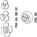
- FIGS. 3a-c are illustrations of examples of various types of rotors that may be used in the rotor-stator unit
- FIG. 3d depicts the rotor of FIG. 3b engaged in a stator.
- the rotor may have a varying number of blades, in a variety of shapes.
- the number of openings in the stator may vary from three and may vary from the illustrated shape.
- any rotor-stator configuration may be used provided that it can substantially produce a sine wave (such as shown in FIG.
- the telemetry system includes a control and drive system, which encodes data obtained by downhole tools according to a modulation scheme that results in operating the motor to drive the rotor relative the stator in motion comprising both oscillating motion and full rotational motion of the rotor.
- the modulation scheme is a QAM modulation scheme which is interpreted to result in both oscillating motion and full rotational motion of the rotor relative the stator.
- the rotor is driven according to classic rotation (full rotational motion) when the data is encoded using maximum amplitude.
- the trajectory algorithm is a quadrature amplitude modulation (QAM) trajectory algorithm according to formulas (2) and (3):
- QAM quadrature amplitude modulation
- S t Pmax ⁇ Pmin ⁇ Sin 2 ⁇ ft + ⁇ n ⁇ A n
- trajectory t n Asin Sin 2 ⁇ ft + ⁇ n ⁇ A n
- a n is the amplitude, provided that amplitude and phase transitions are performed simultaneously by using a trajectory ⁇ ((t) which possesses the following attributes:
- the modulation scheme is a QAM modulation scheme based on a circular constellation diagram, wherein notations (symbols) on the outermost ring of the constellation diagrams result in the motor driving the rotor in a classic rotational (fully rotational) movement.
- FIGS. 4a and 4b illustrate embodiments of a 16-QAM circular constellation diagram and QAM circular constellation diagram with only two amplitudes, respectively. With respect to the 16-QAM diagram, the innermost ring represents 25% amplitude, the next innermost ring represents 50% amplitude, the third ring represents 75% amplitude, and the outermost ring represents 100% amplitude. Symbols with the closest amplitude are placed on the same circle.
- QAM modulation schemes based on a circular constellation diagram reduce the time when the stator openings are partially closed by a 25% factor with a minimum loss of signal to noise ratio.
- one or more downhole tools record data
- a telemetry system transmits at least a portion of the data as modulated mud pulses representative of the recorded data
- a demodulator may reconstruct the original, recorded data.
- Some methods according to this disclosure involve driving a rotor-stator unit disposed within a drill string according to a modulation scheme resulting in both oscillating movement and full rotational movement of the rotor relative the stator, wherein the movement generates the modulated mud pulses, i.e. an encoded signal comprising pressure fluctuations in drilling fluid passing through the rotor-stator unit.
- the modulation scheme can be, for example, any of the modulation schemes described above.
- FIGS. 6a and 6b graphically illustrate the result of a comparative example demonstrating the power advantage of some embodiments of devices, systems, and methods according to this disclosure.
- a QAM trajectory according to this disclosure (involving both oscillating and rotational motion) and a traditional QPSK trajectory were tested on an MWD tool with the following characteristics:
Landscapes
- Engineering & Computer Science (AREA)
- Physics & Mathematics (AREA)
- Life Sciences & Earth Sciences (AREA)
- Mining & Mineral Resources (AREA)
- Geology (AREA)
- Remote Sensing (AREA)
- Environmental & Geological Engineering (AREA)
- Fluid Mechanics (AREA)
- Geophysics (AREA)
- Acoustics & Sound (AREA)
- General Life Sciences & Earth Sciences (AREA)
- Geochemistry & Mineralogy (AREA)
- Earth Drilling (AREA)
- Control Of Motors That Do Not Use Commutators (AREA)
Claims (14)
- Vorrichtung zur Bohrschlamm-Druckpuls-Telemetrie (110), umfassend:a. eine motorisch angetriebene, für die Verwendung in einem Bohrstrang (12) ausgelegte Rotor-Stator-Kombination (200); wobei der Rotor (210) Blätter (215) umfasst und der Stator (220) Öffnungen (225) umfasst, undb. ein Antriebs- und Steuersystem, das ausgelegt ist, den Motor so anzusteuern, dass er den Rotor in Bezug auf den Stator in Rotation um eine vorbestimmte Achse gemäß einem Modulationsschema antreibt, das zu einer Bewegung führt, die sowohl eine oszillierende Bewegung als auch eine volle Rotation umfasst,wobei das Modulationsschema gemäß einem Algorithmus der Formel 1 ausgeführt wird:

wobei der Trajektorienalgorithmus ein wie folgt definierter QAM-Trajektorienalgorithmus ist:

wobei Amplituden- und Phasenwechsel unter Verwendung einer Trajektorie φ(t) gleichzeitig ausgeführt werden, welche die folgenden Attribute besitzt:- φ(t) ist zweimal ableitbar für t von tn bis t n+1- φ(tn) = 0 und φ(t n+ 1)=1- φ(t) ist eine Funktion, die einen reibungslosen Ablauf des Wechsels von der Trajektorie tn zu t n+1 ermöglicht. - Vorrichtung (110) nach Anspruch 1, wobei der Rotor (210) Blätter (215) aufweist, die eine Form aufweisen, und der Rotor geeignet ist, eine Sinuswelle zu erzeugen, die eine Amplitude aufweist, wenn die Blätter mit konstanter Drehzahl gedreht werden, und das Modulationsschema so gestaltet ist, dass es auf die volle Amplitude der auf der Rotorform basierenden Sinuswelle zugreifen kann.
- Vorrichtung (110) nach Anspruch 1, wobei, wenn An=1, der Motor den Rotor (210) so antreiben kann, dass er die Trajektorie φ(t) fortsetzt, ohne sich bei einem maximalen oder minimalen Druck rückwärts zu bewegen.
- Vorrichtung nach Anspruch 1, wobei das Modulationsschema auf einem kreisförmigen Konstellationsdiagramm basiert.
- Vorrichtung nach Anspruch 4, wobei das kreisförmige Konstellationsdiagramm wenigstens zwei konzentrische Ringe aufweist.
- Vorrichtung nach Anspruch 5, wobei das kreisförmige Konstellationsdiagramm einen ersten, innersten Ring, der für eine Amplitude von 25% steht, einen zweiten Ring, der für eine Amplitude von 50% steht, einen dritten Ring, der für eine Amplitude von 75% steht, und einen vierten, äußersten Ring, der für eine volle Amplitude steht, aufweist.
- Vorrichtung nach Anspruch 5 oder 6, wobei ein auf einem äußersten Ring gelegener Punkt bewirkt, dass der Motor den Rotor so antreibt, dass er seine Trajektorie fortsetzt, ohne sich rückwärts zu bewegen.
- Bohrschlamm-Druckpuls-Telemetriesystem, umfassend eine Vorrichtung nach Anspruch 1.
- Bohrschlamm-Druckpuls-Telemetriesystem nach Anspruch 8, wobei das Steuer- und Antriebssystem einen Motor zum Antreiben des Rotors und einen Befehle zum Antreiben des Motors umfassenden Prozessor umfasst.
- Bohrschlamm-Druckpuls-Telemetriesystem nach Anspruch 8 oder 9, wobei das Modulationsschema umfasst, den Motor so anzutreiben, dass er den Rotor in voller Rotation antreibt, falls die maximale Amplitude erreicht wird.
- Bohrschlamm-Druckpuls-Telemetriesystem nach einem der Ansprüche 8 bis 10, ferner umfassend einen Prozessor (85) zum Decodieren von Druckschwankungen in der Bohrspülung, die aus einer Bewegung des Rotors resultieren.
- Bohrschlamm-Druckpuls-Telemetrieverfahren zum Übermitteln von Untertage gemessenen Informationen, umfassend: Antreiben einer in einem Bohrstrang (12) angeordneten Rotor-Stator-Einheit (200) gemäß einem Modulationsschema, das sowohl zu einer oszillierenden Bewegung als auch einer vollen Rotation des Rotors (210) in Bezug auf den Stator (220) und um eine vorbestimmte Achse führt, wobei der Rotor Blätter (215) und der Stator Öffnungen (225) umfasst, wobei die Bewegung des Rotors ein codiertes Signal erzeugt, das Druckschwankungen in der durch die Rotor-Stator-Einheit hindurchtretenden Bohrspülung umfasst,
wobei das Modulationsschema ausgeführt wird gemäß
wobei der Trajektorienalgorithmus ein wie folgt definierter QAM-Trajektorienalgorithmus ist:

wobei Amplituden- und Phasenwechsel unter Verwendung einer Trajektorie φ(t) gleichzeitig ausgeführt werden, welche die folgenden Attribute besitzt:- φ(t) ist zweimal ableitbar für t von tn bis t n+1- φ(tn) = 0 und φ(t n+ 1)=1- φ(t) ist eine Funktion, die einen reibungslosen Ablauf des Wechsels von der Trajektorie tn zu t n+1 ermöglicht. - Bohrschlamm-Druckpuls-Telemetrieverfahren nach Anspruch 12, wobei das Verfahren, wenn An=1, umfasst, den Rotor (210) so anzutreiben, dass er die Trajektorie φ(t) fortsetzt, ohne sich bei einem maximalen oder minimalen Druck rückwärts zu bewegen.
- Bohrschlamm-Druckpuls-Telemetrieverfahren nach Anspruch 12, wobei das Modulationsschema auf einem kreisförmigen Konstellationsdiagramm basiert, das einen äußersten Ring umfasst, und das Verfahren, wenn das Modulationsschema einen Punkt auf dem äußersten Ring einschließt, umfasst, den Rotor so anzutreiben, dass er seine Trajektorie fortsetzt, ohne sich bei einem maximalen oder minimalen Druck rückwärts zu bewegen.
Priority Applications (3)
| Application Number | Priority Date | Filing Date | Title |
|---|---|---|---|
| EP12306583.1A EP2743448B1 (de) | 2012-12-13 | 2012-12-13 | Druckimpuls-Telemetrievorrichtungen, -systeme und -verfahren |
| PCT/US2013/074850 WO2014093735A1 (en) | 2012-12-13 | 2013-12-13 | Mud pulse telemetry devices, systems, and methods |
| US14/652,123 US9695686B2 (en) | 2012-12-13 | 2013-12-13 | Mud pulse telemetry devices, systems, and methods |
Applications Claiming Priority (1)
| Application Number | Priority Date | Filing Date | Title |
|---|---|---|---|
| EP12306583.1A EP2743448B1 (de) | 2012-12-13 | 2012-12-13 | Druckimpuls-Telemetrievorrichtungen, -systeme und -verfahren |
Publications (2)
| Publication Number | Publication Date |
|---|---|
| EP2743448A1 EP2743448A1 (de) | 2014-06-18 |
| EP2743448B1 true EP2743448B1 (de) | 2017-08-23 |
Family
ID=47504745
Family Applications (1)
| Application Number | Title | Priority Date | Filing Date |
|---|---|---|---|
| EP12306583.1A Not-in-force EP2743448B1 (de) | 2012-12-13 | 2012-12-13 | Druckimpuls-Telemetrievorrichtungen, -systeme und -verfahren |
Country Status (3)
| Country | Link |
|---|---|
| US (1) | US9695686B2 (de) |
| EP (1) | EP2743448B1 (de) |
| WO (1) | WO2014093735A1 (de) |
Families Citing this family (6)
| Publication number | Priority date | Publication date | Assignee | Title |
|---|---|---|---|---|
| US9784097B2 (en) | 2015-03-30 | 2017-10-10 | Baker Hughes Incorporated | Compressed telemetry for time series downhole data using variable scaling and grouped words |
| EP3329094A4 (de) | 2015-10-21 | 2019-04-03 | Halliburton Energy Services, Inc. | Druckpulstelemetrieinstrument mit ventil mit niedrigem drehmoment |
| US10145239B1 (en) * | 2017-05-24 | 2018-12-04 | General Electric Company | Flow modulator for use in a drilling system |
| RU2691194C1 (ru) * | 2018-08-02 | 2019-06-11 | федеральное государственное бюджетное образовательное учреждение высшего образования "Пермский национальный исследовательский политехнический университет" | Модульная управляемая система роторного бурения скважин малого диаметра |
| CN114650103B (zh) * | 2020-12-21 | 2023-09-08 | 航天科工惯性技术有限公司 | 一种泥浆脉冲数据传输方法、装置、设备及存储介质 |
| CN115853504B (zh) * | 2022-12-30 | 2024-10-22 | 北京恒泰万博石油技术股份有限公司 | 一种连续波泥浆脉冲信号模拟试验装置及方法 |
Family Cites Families (7)
| Publication number | Priority date | Publication date | Assignee | Title |
|---|---|---|---|---|
| US5583827A (en) * | 1993-07-23 | 1996-12-10 | Halliburton Company | Measurement-while-drilling system and method |
| US6714138B1 (en) * | 2000-09-29 | 2004-03-30 | Aps Technology, Inc. | Method and apparatus for transmitting information to the surface from a drill string down hole in a well |
| US6626253B2 (en) * | 2001-02-27 | 2003-09-30 | Baker Hughes Incorporated | Oscillating shear valve for mud pulse telemetry |
| US7735579B2 (en) * | 2005-09-12 | 2010-06-15 | Teledrift, Inc. | Measurement while drilling apparatus and method of using the same |
| US8485264B2 (en) * | 2009-03-12 | 2013-07-16 | Schlumberger Technology Corporation | Multi-stage modulator |
| US8294591B2 (en) * | 2009-03-30 | 2012-10-23 | Schlumberger Technology Corporation | Digital signal processing receivers, systems and methods for identifying decoded signals |
| US8654832B1 (en) * | 2012-09-11 | 2014-02-18 | Baker Hughes Incorporated | Apparatus and method for coding and modulation |
-
2012
- 2012-12-13 EP EP12306583.1A patent/EP2743448B1/de not_active Not-in-force
-
2013
- 2013-12-13 US US14/652,123 patent/US9695686B2/en active Active
- 2013-12-13 WO PCT/US2013/074850 patent/WO2014093735A1/en not_active Ceased
Non-Patent Citations (1)
| Title |
|---|
| None * |
Also Published As
| Publication number | Publication date |
|---|---|
| US20150322780A1 (en) | 2015-11-12 |
| WO2014093735A4 (en) | 2014-08-07 |
| EP2743448A1 (de) | 2014-06-18 |
| WO2014093735A1 (en) | 2014-06-19 |
| US9695686B2 (en) | 2017-07-04 |
Similar Documents
| Publication | Publication Date | Title |
|---|---|---|
| US9695686B2 (en) | Mud pulse telemetry devices, systems, and methods | |
| US8151905B2 (en) | Downhole telemetry system and method | |
| US10215021B2 (en) | Downhole electromagnetic and mud pulse telemetry apparatus | |
| US8164477B2 (en) | Joint channel coding and modulation for improved performance of telemetry systems | |
| US10669843B2 (en) | Dual rotor pulser for transmitting information in a drilling system | |
| US10465506B2 (en) | Mud-pulse telemetry system including a pulser for transmitting information along a drill string | |
| US9691274B2 (en) | Pressure wave transmission apparatus for data communication in a liquid comprising a plurality of rotors, pressure wave receiving apparatus comprising a waveform correlation process, pressure wave communication system and program product | |
| CN101949287A (zh) | 基于钻井液连续压力波技术的井下随钻测量数据调制方法及装置 | |
| RU2705648C1 (ru) | Устройство гидроимпульсной скважинной телеметрии, содержащее клапан с малым моментом вращения | |
| CN113622899B (zh) | 一种钻井液连续波信号调制系统及方法 | |
| US10808505B2 (en) | High signal strength mud siren for MWD telemetry | |
| US10605076B2 (en) | High amplitude pulse generator for down-hole tools | |
| RU2671376C1 (ru) | Способ и устройство для генерирования импульсов в столбе флюида | |
| WO2024205638A1 (en) | Encoding data across different downlink channels |
Legal Events
| Date | Code | Title | Description |
|---|---|---|---|
| PUAI | Public reference made under article 153(3) epc to a published international application that has entered the european phase |
Free format text: ORIGINAL CODE: 0009012 |
|
| 17P | Request for examination filed |
Effective date: 20121213 |
|
| AK | Designated contracting states |
Kind code of ref document: A1 Designated state(s): AL AT BE BG CH CY CZ DE DK EE ES FI FR GB GR HR HU IE IS IT LI LT LU LV MC MK MT NL NO PL PT RO RS SE SI SK SM TR |
|
| AX | Request for extension of the european patent |
Extension state: BA ME |
|
| R17P | Request for examination filed (corrected) |
Effective date: 20141209 |
|
| RBV | Designated contracting states (corrected) |
Designated state(s): AL AT BE BG CH CY CZ DE DK EE ES FI FR GB GR HR HU IE IS IT LI LT LU LV MC MK MT NL NO PL PT RO RS SE SI SK SM TR |
|
| 17Q | First examination report despatched |
Effective date: 20160831 |
|
| GRAP | Despatch of communication of intention to grant a patent |
Free format text: ORIGINAL CODE: EPIDOSNIGR1 |
|
| INTG | Intention to grant announced |
Effective date: 20170314 |
|
| GRAS | Grant fee paid |
Free format text: ORIGINAL CODE: EPIDOSNIGR3 |
|
| GRAA | (expected) grant |
Free format text: ORIGINAL CODE: 0009210 |
|
| AK | Designated contracting states |
Kind code of ref document: B1 Designated state(s): AL AT BE BG CH CY CZ DE DK EE ES FI FR GB GR HR HU IE IS IT LI LT LU LV MC MK MT NL NO PL PT RO RS SE SI SK SM TR |
|
| REG | Reference to a national code |
Ref country code: GB Ref legal event code: FG4D |
|
| REG | Reference to a national code |
Ref country code: CH Ref legal event code: EP |
|
| REG | Reference to a national code |
Ref country code: AT Ref legal event code: REF Ref document number: 921562 Country of ref document: AT Kind code of ref document: T Effective date: 20170915 |
|
| REG | Reference to a national code |
Ref country code: IE Ref legal event code: FG4D |
|
| REG | Reference to a national code |
Ref country code: DE Ref legal event code: R096 Ref document number: 602012036239 Country of ref document: DE |
|
| REG | Reference to a national code |
Ref country code: NL Ref legal event code: MP Effective date: 20170823 |
|
| REG | Reference to a national code |
Ref country code: LT Ref legal event code: MG4D |
|
| REG | Reference to a national code |
Ref country code: AT Ref legal event code: MK05 Ref document number: 921562 Country of ref document: AT Kind code of ref document: T Effective date: 20170823 |
|
| PG25 | Lapsed in a contracting state [announced via postgrant information from national office to epo] |
Ref country code: SE Free format text: LAPSE BECAUSE OF FAILURE TO SUBMIT A TRANSLATION OF THE DESCRIPTION OR TO PAY THE FEE WITHIN THE PRESCRIBED TIME-LIMIT Effective date: 20170823 Ref country code: FI Free format text: LAPSE BECAUSE OF FAILURE TO SUBMIT A TRANSLATION OF THE DESCRIPTION OR TO PAY THE FEE WITHIN THE PRESCRIBED TIME-LIMIT Effective date: 20170823 Ref country code: AT Free format text: LAPSE BECAUSE OF FAILURE TO SUBMIT A TRANSLATION OF THE DESCRIPTION OR TO PAY THE FEE WITHIN THE PRESCRIBED TIME-LIMIT Effective date: 20170823 Ref country code: NO Free format text: LAPSE BECAUSE OF FAILURE TO SUBMIT A TRANSLATION OF THE DESCRIPTION OR TO PAY THE FEE WITHIN THE PRESCRIBED TIME-LIMIT Effective date: 20171123 Ref country code: LT Free format text: LAPSE BECAUSE OF FAILURE TO SUBMIT A TRANSLATION OF THE DESCRIPTION OR TO PAY THE FEE WITHIN THE PRESCRIBED TIME-LIMIT Effective date: 20170823 Ref country code: HR Free format text: LAPSE BECAUSE OF FAILURE TO SUBMIT A TRANSLATION OF THE DESCRIPTION OR TO PAY THE FEE WITHIN THE PRESCRIBED TIME-LIMIT Effective date: 20170823 Ref country code: NL Free format text: LAPSE BECAUSE OF FAILURE TO SUBMIT A TRANSLATION OF THE DESCRIPTION OR TO PAY THE FEE WITHIN THE PRESCRIBED TIME-LIMIT Effective date: 20170823 |
|
| PG25 | Lapsed in a contracting state [announced via postgrant information from national office to epo] |
Ref country code: PL Free format text: LAPSE BECAUSE OF FAILURE TO SUBMIT A TRANSLATION OF THE DESCRIPTION OR TO PAY THE FEE WITHIN THE PRESCRIBED TIME-LIMIT Effective date: 20170823 Ref country code: LV Free format text: LAPSE BECAUSE OF FAILURE TO SUBMIT A TRANSLATION OF THE DESCRIPTION OR TO PAY THE FEE WITHIN THE PRESCRIBED TIME-LIMIT Effective date: 20170823 Ref country code: GR Free format text: LAPSE BECAUSE OF FAILURE TO SUBMIT A TRANSLATION OF THE DESCRIPTION OR TO PAY THE FEE WITHIN THE PRESCRIBED TIME-LIMIT Effective date: 20171124 Ref country code: ES Free format text: LAPSE BECAUSE OF FAILURE TO SUBMIT A TRANSLATION OF THE DESCRIPTION OR TO PAY THE FEE WITHIN THE PRESCRIBED TIME-LIMIT Effective date: 20170823 Ref country code: IS Free format text: LAPSE BECAUSE OF FAILURE TO SUBMIT A TRANSLATION OF THE DESCRIPTION OR TO PAY THE FEE WITHIN THE PRESCRIBED TIME-LIMIT Effective date: 20171223 Ref country code: RS Free format text: LAPSE BECAUSE OF FAILURE TO SUBMIT A TRANSLATION OF THE DESCRIPTION OR TO PAY THE FEE WITHIN THE PRESCRIBED TIME-LIMIT Effective date: 20170823 Ref country code: BG Free format text: LAPSE BECAUSE OF FAILURE TO SUBMIT A TRANSLATION OF THE DESCRIPTION OR TO PAY THE FEE WITHIN THE PRESCRIBED TIME-LIMIT Effective date: 20171123 |
|
| PGFP | Annual fee paid to national office [announced via postgrant information from national office to epo] |
Ref country code: GB Payment date: 20171228 Year of fee payment: 6 |
|
| PG25 | Lapsed in a contracting state [announced via postgrant information from national office to epo] |
Ref country code: DK Free format text: LAPSE BECAUSE OF FAILURE TO SUBMIT A TRANSLATION OF THE DESCRIPTION OR TO PAY THE FEE WITHIN THE PRESCRIBED TIME-LIMIT Effective date: 20170823 Ref country code: RO Free format text: LAPSE BECAUSE OF FAILURE TO SUBMIT A TRANSLATION OF THE DESCRIPTION OR TO PAY THE FEE WITHIN THE PRESCRIBED TIME-LIMIT Effective date: 20170823 Ref country code: CZ Free format text: LAPSE BECAUSE OF FAILURE TO SUBMIT A TRANSLATION OF THE DESCRIPTION OR TO PAY THE FEE WITHIN THE PRESCRIBED TIME-LIMIT Effective date: 20170823 |
|
| REG | Reference to a national code |
Ref country code: DE Ref legal event code: R097 Ref document number: 602012036239 Country of ref document: DE |
|
| PG25 | Lapsed in a contracting state [announced via postgrant information from national office to epo] |
Ref country code: SK Free format text: LAPSE BECAUSE OF FAILURE TO SUBMIT A TRANSLATION OF THE DESCRIPTION OR TO PAY THE FEE WITHIN THE PRESCRIBED TIME-LIMIT Effective date: 20170823 Ref country code: IT Free format text: LAPSE BECAUSE OF FAILURE TO SUBMIT A TRANSLATION OF THE DESCRIPTION OR TO PAY THE FEE WITHIN THE PRESCRIBED TIME-LIMIT Effective date: 20170823 Ref country code: SM Free format text: LAPSE BECAUSE OF FAILURE TO SUBMIT A TRANSLATION OF THE DESCRIPTION OR TO PAY THE FEE WITHIN THE PRESCRIBED TIME-LIMIT Effective date: 20170823 Ref country code: EE Free format text: LAPSE BECAUSE OF FAILURE TO SUBMIT A TRANSLATION OF THE DESCRIPTION OR TO PAY THE FEE WITHIN THE PRESCRIBED TIME-LIMIT Effective date: 20170823 |
|
| PLBE | No opposition filed within time limit |
Free format text: ORIGINAL CODE: 0009261 |
|
| STAA | Information on the status of an ep patent application or granted ep patent |
Free format text: STATUS: NO OPPOSITION FILED WITHIN TIME LIMIT |
|
| REG | Reference to a national code |
Ref country code: DE Ref legal event code: R119 Ref document number: 602012036239 Country of ref document: DE |
|
| REG | Reference to a national code |
Ref country code: CH Ref legal event code: PL |
|
| 26N | No opposition filed |
Effective date: 20180524 |
|
| PG25 | Lapsed in a contracting state [announced via postgrant information from national office to epo] |
Ref country code: SI Free format text: LAPSE BECAUSE OF FAILURE TO SUBMIT A TRANSLATION OF THE DESCRIPTION OR TO PAY THE FEE WITHIN THE PRESCRIBED TIME-LIMIT Effective date: 20170823 |
|
| REG | Reference to a national code |
Ref country code: IE Ref legal event code: MM4A |
|
| PG25 | Lapsed in a contracting state [announced via postgrant information from national office to epo] |
Ref country code: LU Free format text: LAPSE BECAUSE OF NON-PAYMENT OF DUE FEES Effective date: 20171213 Ref country code: MT Free format text: LAPSE BECAUSE OF NON-PAYMENT OF DUE FEES Effective date: 20171213 |
|
| REG | Reference to a national code |
Ref country code: FR Ref legal event code: ST Effective date: 20180831 |
|
| REG | Reference to a national code |
Ref country code: BE Ref legal event code: MM Effective date: 20171231 |
|
| PG25 | Lapsed in a contracting state [announced via postgrant information from national office to epo] |
Ref country code: IE Free format text: LAPSE BECAUSE OF NON-PAYMENT OF DUE FEES Effective date: 20171213 Ref country code: FR Free format text: LAPSE BECAUSE OF NON-PAYMENT OF DUE FEES Effective date: 20180102 Ref country code: DE Free format text: LAPSE BECAUSE OF NON-PAYMENT OF DUE FEES Effective date: 20180703 |
|
| PG25 | Lapsed in a contracting state [announced via postgrant information from national office to epo] |
Ref country code: BE Free format text: LAPSE BECAUSE OF NON-PAYMENT OF DUE FEES Effective date: 20171231 Ref country code: LI Free format text: LAPSE BECAUSE OF NON-PAYMENT OF DUE FEES Effective date: 20171231 Ref country code: CH Free format text: LAPSE BECAUSE OF NON-PAYMENT OF DUE FEES Effective date: 20171231 |
|
| PG25 | Lapsed in a contracting state [announced via postgrant information from national office to epo] |
Ref country code: HU Free format text: LAPSE BECAUSE OF FAILURE TO SUBMIT A TRANSLATION OF THE DESCRIPTION OR TO PAY THE FEE WITHIN THE PRESCRIBED TIME-LIMIT; INVALID AB INITIO Effective date: 20121213 Ref country code: MC Free format text: LAPSE BECAUSE OF FAILURE TO SUBMIT A TRANSLATION OF THE DESCRIPTION OR TO PAY THE FEE WITHIN THE PRESCRIBED TIME-LIMIT Effective date: 20170823 |
|
| GBPC | Gb: european patent ceased through non-payment of renewal fee |
Effective date: 20181213 |
|
| PG25 | Lapsed in a contracting state [announced via postgrant information from national office to epo] |
Ref country code: CY Free format text: LAPSE BECAUSE OF NON-PAYMENT OF DUE FEES Effective date: 20170823 |
|
| PG25 | Lapsed in a contracting state [announced via postgrant information from national office to epo] |
Ref country code: MK Free format text: LAPSE BECAUSE OF FAILURE TO SUBMIT A TRANSLATION OF THE DESCRIPTION OR TO PAY THE FEE WITHIN THE PRESCRIBED TIME-LIMIT Effective date: 20170823 |
|
| PG25 | Lapsed in a contracting state [announced via postgrant information from national office to epo] |
Ref country code: GB Free format text: LAPSE BECAUSE OF NON-PAYMENT OF DUE FEES Effective date: 20181213 |
|
| PG25 | Lapsed in a contracting state [announced via postgrant information from national office to epo] |
Ref country code: TR Free format text: LAPSE BECAUSE OF FAILURE TO SUBMIT A TRANSLATION OF THE DESCRIPTION OR TO PAY THE FEE WITHIN THE PRESCRIBED TIME-LIMIT Effective date: 20170823 |
|
| PG25 | Lapsed in a contracting state [announced via postgrant information from national office to epo] |
Ref country code: PT Free format text: LAPSE BECAUSE OF FAILURE TO SUBMIT A TRANSLATION OF THE DESCRIPTION OR TO PAY THE FEE WITHIN THE PRESCRIBED TIME-LIMIT Effective date: 20170823 |
|
| PG25 | Lapsed in a contracting state [announced via postgrant information from national office to epo] |
Ref country code: AL Free format text: LAPSE BECAUSE OF FAILURE TO SUBMIT A TRANSLATION OF THE DESCRIPTION OR TO PAY THE FEE WITHIN THE PRESCRIBED TIME-LIMIT Effective date: 20170823 |