EP2743506A2 - Gaspumpe mit abdichtender Ölnut - Google Patents
Gaspumpe mit abdichtender Ölnut Download PDFInfo
- Publication number
- EP2743506A2 EP2743506A2 EP13196532.9A EP13196532A EP2743506A2 EP 2743506 A2 EP2743506 A2 EP 2743506A2 EP 13196532 A EP13196532 A EP 13196532A EP 2743506 A2 EP2743506 A2 EP 2743506A2
- Authority
- EP
- European Patent Office
- Prior art keywords
- liquid
- sealing
- pump
- gas pump
- delivery chamber
- Prior art date
- Legal status (The legal status is an assumption and is not a legal conclusion. Google has not performed a legal analysis and makes no representation as to the accuracy of the status listed.)
- Granted
Links
Images



Classifications
-
- F—MECHANICAL ENGINEERING; LIGHTING; HEATING; WEAPONS; BLASTING
- F04—POSITIVE - DISPLACEMENT MACHINES FOR LIQUIDS; PUMPS FOR LIQUIDS OR ELASTIC FLUIDS
- F04C—ROTARY-PISTON, OR OSCILLATING-PISTON, POSITIVE-DISPLACEMENT MACHINES FOR LIQUIDS; ROTARY-PISTON, OR OSCILLATING-PISTON, POSITIVE-DISPLACEMENT PUMPS
- F04C27/00—Sealing arrangements in rotary-piston pumps specially adapted for elastic fluids
- F04C27/02—Liquid sealing for high-vacuum pumps or for compressors
-
- F—MECHANICAL ENGINEERING; LIGHTING; HEATING; WEAPONS; BLASTING
- F04—POSITIVE - DISPLACEMENT MACHINES FOR LIQUIDS; PUMPS FOR LIQUIDS OR ELASTIC FLUIDS
- F04C—ROTARY-PISTON, OR OSCILLATING-PISTON, POSITIVE-DISPLACEMENT MACHINES FOR LIQUIDS; ROTARY-PISTON, OR OSCILLATING-PISTON, POSITIVE-DISPLACEMENT PUMPS
- F04C18/00—Rotary-piston pumps specially adapted for elastic fluids
- F04C18/30—Rotary-piston pumps specially adapted for elastic fluids having the characteristics covered by two or more of groups F04C18/02, F04C18/08, F04C18/22, F04C18/24, F04C18/48, or having the characteristics covered by one of these groups together with some other type of movement between co-operating members
- F04C18/34—Rotary-piston pumps specially adapted for elastic fluids having the characteristics covered by two or more of groups F04C18/02, F04C18/08, F04C18/22, F04C18/24, F04C18/48, or having the characteristics covered by one of these groups together with some other type of movement between co-operating members having the movement defined in group F04C18/08 or F04C18/22 and relative reciprocation between the co-operating members
- F04C18/344—Rotary-piston pumps specially adapted for elastic fluids having the characteristics covered by two or more of groups F04C18/02, F04C18/08, F04C18/22, F04C18/24, F04C18/48, or having the characteristics covered by one of these groups together with some other type of movement between co-operating members having the movement defined in group F04C18/08 or F04C18/22 and relative reciprocation between the co-operating members with vanes reciprocating with respect to the inner member
- F04C18/3441—Rotary-piston pumps specially adapted for elastic fluids having the characteristics covered by two or more of groups F04C18/02, F04C18/08, F04C18/22, F04C18/24, F04C18/48, or having the characteristics covered by one of these groups together with some other type of movement between co-operating members having the movement defined in group F04C18/08 or F04C18/22 and relative reciprocation between the co-operating members with vanes reciprocating with respect to the inner member the inner and outer member being in contact along one line or continuous surface substantially parallel to the axis of rotation
- F04C18/3442—Rotary-piston pumps specially adapted for elastic fluids having the characteristics covered by two or more of groups F04C18/02, F04C18/08, F04C18/22, F04C18/24, F04C18/48, or having the characteristics covered by one of these groups together with some other type of movement between co-operating members having the movement defined in group F04C18/08 or F04C18/22 and relative reciprocation between the co-operating members with vanes reciprocating with respect to the inner member the inner and outer member being in contact along one line or continuous surface substantially parallel to the axis of rotation the surfaces of the inner and outer member, forming the inlet and outlet opening
-
- F—MECHANICAL ENGINEERING; LIGHTING; HEATING; WEAPONS; BLASTING
- F04—POSITIVE - DISPLACEMENT MACHINES FOR LIQUIDS; PUMPS FOR LIQUIDS OR ELASTIC FLUIDS
- F04C—ROTARY-PISTON, OR OSCILLATING-PISTON, POSITIVE-DISPLACEMENT MACHINES FOR LIQUIDS; ROTARY-PISTON, OR OSCILLATING-PISTON, POSITIVE-DISPLACEMENT PUMPS
- F04C2/00—Rotary-piston machines or pumps
- F04C2/30—Rotary-piston machines or pumps having the characteristics covered by two or more groups F04C2/02, F04C2/08, F04C2/22, F04C2/24 or having the characteristics covered by one of these groups together with some other type of movement between co-operating members
- F04C2/34—Rotary-piston machines or pumps having the characteristics covered by two or more groups F04C2/02, F04C2/08, F04C2/22, F04C2/24 or having the characteristics covered by one of these groups together with some other type of movement between co-operating members having the movement defined in groups F04C2/08 or F04C2/22 and relative reciprocation between the co-operating members
- F04C2/356—Rotary-piston machines or pumps having the characteristics covered by two or more groups F04C2/02, F04C2/08, F04C2/22, F04C2/24 or having the characteristics covered by one of these groups together with some other type of movement between co-operating members having the movement defined in groups F04C2/08 or F04C2/22 and relative reciprocation between the co-operating members with vanes reciprocating with respect to the outer member
-
- F—MECHANICAL ENGINEERING; LIGHTING; HEATING; WEAPONS; BLASTING
- F04—POSITIVE - DISPLACEMENT MACHINES FOR LIQUIDS; PUMPS FOR LIQUIDS OR ELASTIC FLUIDS
- F04C—ROTARY-PISTON, OR OSCILLATING-PISTON, POSITIVE-DISPLACEMENT MACHINES FOR LIQUIDS; ROTARY-PISTON, OR OSCILLATING-PISTON, POSITIVE-DISPLACEMENT PUMPS
- F04C23/00—Combinations of two or more pumps, each being of rotary-piston or oscillating-piston type, specially adapted for elastic fluids; Pumping installations specially adapted for elastic fluids; Multi-stage pumps specially adapted for elastic fluids
- F04C23/001—Combinations of two or more pumps, each being of rotary-piston or oscillating-piston type, specially adapted for elastic fluids; Pumping installations specially adapted for elastic fluids; Multi-stage pumps specially adapted for elastic fluids of similar working principle
-
- F—MECHANICAL ENGINEERING; LIGHTING; HEATING; WEAPONS; BLASTING
- F04—POSITIVE - DISPLACEMENT MACHINES FOR LIQUIDS; PUMPS FOR LIQUIDS OR ELASTIC FLUIDS
- F04C—ROTARY-PISTON, OR OSCILLATING-PISTON, POSITIVE-DISPLACEMENT MACHINES FOR LIQUIDS; ROTARY-PISTON, OR OSCILLATING-PISTON, POSITIVE-DISPLACEMENT PUMPS
- F04C29/00—Component parts, details or accessories of pumps or pumping installations, not provided for in groups F04C18/00 - F04C28/00
- F04C29/02—Lubrication; Lubricant separation
- F04C29/025—Lubrication; Lubricant separation using a lubricant pump
-
- F—MECHANICAL ENGINEERING; LIGHTING; HEATING; WEAPONS; BLASTING
- F01—MACHINES OR ENGINES IN GENERAL; ENGINE PLANTS IN GENERAL; STEAM ENGINES
- F01C—ROTARY-PISTON OR OSCILLATING-PISTON MACHINES OR ENGINES
- F01C21/00—Component parts, details or accessories not provided for in groups F01C1/00 - F01C20/00
- F01C21/10—Outer members for co-operation with rotary pistons; Casings
-
- F—MECHANICAL ENGINEERING; LIGHTING; HEATING; WEAPONS; BLASTING
- F04—POSITIVE - DISPLACEMENT MACHINES FOR LIQUIDS; PUMPS FOR LIQUIDS OR ELASTIC FLUIDS
- F04C—ROTARY-PISTON, OR OSCILLATING-PISTON, POSITIVE-DISPLACEMENT MACHINES FOR LIQUIDS; ROTARY-PISTON, OR OSCILLATING-PISTON, POSITIVE-DISPLACEMENT PUMPS
- F04C2/00—Rotary-piston machines or pumps
- F04C2/30—Rotary-piston machines or pumps having the characteristics covered by two or more groups F04C2/02, F04C2/08, F04C2/22, F04C2/24 or having the characteristics covered by one of these groups together with some other type of movement between co-operating members
- F04C2/34—Rotary-piston machines or pumps having the characteristics covered by two or more groups F04C2/02, F04C2/08, F04C2/22, F04C2/24 or having the characteristics covered by one of these groups together with some other type of movement between co-operating members having the movement defined in groups F04C2/08 or F04C2/22 and relative reciprocation between the co-operating members
- F04C2/344—Rotary-piston machines or pumps having the characteristics covered by two or more groups F04C2/02, F04C2/08, F04C2/22, F04C2/24 or having the characteristics covered by one of these groups together with some other type of movement between co-operating members having the movement defined in groups F04C2/08 or F04C2/22 and relative reciprocation between the co-operating members with vanes reciprocating with respect to the inner member
- F04C2/3441—Rotary-piston machines or pumps having the characteristics covered by two or more groups F04C2/02, F04C2/08, F04C2/22, F04C2/24 or having the characteristics covered by one of these groups together with some other type of movement between co-operating members having the movement defined in groups F04C2/08 or F04C2/22 and relative reciprocation between the co-operating members with vanes reciprocating with respect to the inner member the inner and outer member being in contact along one line or continuous surface substantially parallel to the axis of rotation
- F04C2/3442—Rotary-piston machines or pumps having the characteristics covered by two or more groups F04C2/02, F04C2/08, F04C2/22, F04C2/24 or having the characteristics covered by one of these groups together with some other type of movement between co-operating members having the movement defined in groups F04C2/08 or F04C2/22 and relative reciprocation between the co-operating members with vanes reciprocating with respect to the inner member the inner and outer member being in contact along one line or continuous surface substantially parallel to the axis of rotation the surfaces of the inner and outer member, forming the working space, being surfaces of revolution
-
- F—MECHANICAL ENGINEERING; LIGHTING; HEATING; WEAPONS; BLASTING
- F04—POSITIVE - DISPLACEMENT MACHINES FOR LIQUIDS; PUMPS FOR LIQUIDS OR ELASTIC FLUIDS
- F04C—ROTARY-PISTON, OR OSCILLATING-PISTON, POSITIVE-DISPLACEMENT MACHINES FOR LIQUIDS; ROTARY-PISTON, OR OSCILLATING-PISTON, POSITIVE-DISPLACEMENT PUMPS
- F04C25/00—Adaptations of pumps for special use of pumps for elastic fluids
- F04C25/02—Adaptations of pumps for special use of pumps for elastic fluids for producing high vacuum
Definitions
- the invention relates to the sealing of a gas pump, in particular a vacuum pump.
- Vacuum pumps as the invention relates in particular, are used in vehicles, for example, to provide negative pressure for a brake booster.
- the pump can be arranged laterally on the cylinder head of a vehicle engine and driven by a camshaft, as was customary for a long time. Due to space restrictions and also to reduce the specific size of the vacuum pump is recently arranged in tandem with a lubricating oil pump in the oil sump. Because of relatively high demands on the tightness, it has been customary to seal by means of O-ring or profile seal. The seal should prevent air from being sucked in from the environment. In addition, when mounted on the outside of the engine pumps, oil leakage should be prevented. When installed in the oil sump, an absolute oil-tightness of the system to the outside is no longer absolutely necessary. The seal is used practically only to avoid the Heilsaugens.
- the sealing elements such as O-ring and profile form seals, are manufactured separately and placed in a surrounding the delivery chamber sealing groove of a housing part of the gas pump or placed on an end face of the housing part. For assembly and assembly, they are secured to the housing part.
- the sealing elements cause costs that can no longer be neglected, especially in mass production, as is customary in vehicle production. Seen over the life of the pump also suffers the tightness due to material degradation of the sealing elements.
- Gas pumps which are preferably designed as vane pumps as disclosed by the invention, disclose, for example, the US 2012/0060683 A , the US 3,326,456 A and the WO 2007/003215 A1 ,
- the invention is based on a gas pump which has a first housing part with a sealing surface and a second housing part likewise with a sealing surface, furthermore a delivery chamber with an inlet and an outlet for a gas and a delivery device movable in the delivery chamber for conveying the gas.
- the two housing parts alone can form the delivery chamber with one another, in particular completely enclosing the delivery chamber apart from one or more inlets and one or more outlets.
- the first housing part and the second housing part may enclose the delivery chamber together with one or more further housing parts of the gas pump.
- One of the two housing parts, for example the second housing part may in particular be a housing cover which closes off the delivery chamber at one end face.
- the housing parts are joined together, so that they at least partially, preferably completely enclose the delivery chamber over a chamber circumference and with the said sealing surfaces to form a sealing joint to each other to seal the delivery chamber.
- the sealing surfaces are preferably pressed against each other, for example by the housing parts are joined together by means of screw.
- a sealing recess which is filled during operation of the gas pump with a sealing liquid.
- the sealing recess is completely filled with the sealing liquid.
- the degree of filling of the sealing recess is at least so great that the sealing of the delivery chamber is ensured by the sealing liquid located in the sealing recess in an extent required for practical purposes.
- the sealing recess is filled only with the sealing liquid. Anyhow, the sealing liquid in the Sealing recess first the tightness of the delivery chamber over the sealing joint of the sealing surfaces away safely.
- the sealing recess may extend continuously over the entire circumference of the delivery chamber, i. over 360 °. In modifications, it may be locally interrupted at one or more locations over its circumference. In principle, it may also extend over only a part of the circumference, but in such embodiments preferably over the greater part of the circumference. It should also not be ruled out that the housing part, in which the sealing recess is provided, extends only over part of the circumference of the delivery chamber.
- a sealing recess is formed, preferably in such a way that the in the plurality of housing parts provided sealing recesses together the delivery chamber over its entire circumference continuously surrounded, so merge into one another or connect to each other without interruption. Modifications in the above sense, however, are possible in such embodiments.
- the sealing recess is delimited both along an inner edge facing the delivery chamber and along an outer edge facing away from the delivery chamber from the sealing surface in which the sealing depression is formed.
- the sealing recess is formed in other words in an end view of the sealing surface seen within the sealing surface, but this does not preclude that this sealing recess is in places with an inner or an outer edge of the sealing surface in connection, for example via one or more of the sealing recess inwards or outside branching, groove-shaped channel or channels.
- Such a channel can for example serve to supply the sealing liquid into the sealing recess.
- the previously separately manufactured sealing ring can be saved, the assembly of the gas pump can be simplified and consequently costs can be reduced.
- the sealing groove is usually machined.
- a machining can in accordance with the invention Sealing recess eliminated.
- the sealing depression can be formed directly in a primary molding, for example, a casting, molded or subsequently by embossing, whereby the manufacturing costs can be further reduced. Due to the reduction in parts also reduces the logistics and testing costs in the parts production and installation of the gas pump.
- the gas pump may in particular be designed as a vacuum pump and used to supply one or more units, preferably one or more units of a motor vehicle, with negative pressure or be provided for such use.
- One application to which the invention is directed is that of a vacuum pump for supplying a brake booster or other aggregate of a motor vehicle with negative pressure.
- the gas pump can basically also serve to supply one or more units with compressed gas.
- the gas can be air, but in principle also another gas.
- the gas pump can be designed as a rotary pump.
- the conveyor as a whole may be rotatable in the delivery chamber about an axis of rotation or comprise at least one in the delivery chamber about a rotation axis rotatable conveyor member.
- the conveyor may also comprise a plurality of rotatable conveyor members rotatable about spaced apart axes of rotation.
- the gas pump may be a vane pump and the delivery device may comprise one or more delivery rotors, each having a single or multiple vanes.
- the sealing recess is connected via a supply to a reservoir or a circuit of the sealing liquid, so that the sealing liquid of the sealing recess can be supplied in the assembled state of the housing parts.
- the sealing recess may also be tightly closed without the possibility of supplying sealing liquid.
- the connection of the sealing depression to a reservoir or a circulation has the advantage that the sealing depression can also be supplied subsequently, ie after the assembly of the gas pump, sealing liquid, for example for initial or repeated filling of the sealing depression or for compensation from the sealing joint or by an optional local discharge from the sealing recess compressed sealing liquid.
- the sealing liquid may be a liquid which is used in the vicinity of the gas pump for a different purpose, for example as a working liquid, such as a hydraulic oil, another unit.
- a liquid lubricant forms the sealing liquid.
- This may be the same lubricant that also serves to lubricate the conveyor and / or seal conveyor cells formed in the delivery chamber. If the gas pump is assigned to an internal combustion engine of a motor vehicle, aircraft or watercraft, in particular a lubricant serving for lubricating the internal combustion engine can also form the sealing fluid in a further function.
- the sealing liquid can advantageously serve for the lubrication of the conveying device and / or sealing purposes, for example the sealing, optionally within the conveying chamber of formed conveying cells.
- a connection may exist between the sealing recess and the delivery chamber, such that lubricant initially serving as sealant in the sealing recess can penetrate from the sealing depression into the delivery chamber.
- one or more local connections or discharges provided in the region of the sealing joint between the sealing recess and the delivery chamber or the entire region of the sealing joint, which is located between the sealing recess and the delivery chamber be performed evenly with a certain leakage to a small Allow flow of sealing liquid, respectively lubricant, from the sealing recess into the delivery chamber.
- Such a flow in the direction of the delivery chamber is favored in embodiments in which the gas pump is a vacuum pump, as is preferred, because of the negative pressure prevailing in the delivery chamber during operation of the gas pump.
- the invention also relates to a combination of the gas pump with a liquid pump, which serves to supply an aggregate with a liquid, such as a working fluid or a liquid lubricant, said liquid also forms the sealing liquid for the gas pump in a further function.
- the liquid pump may in particular be a lubricant pump for supply Serve an internal combustion engine or other aggregate with liquid lubricant.
- the liquid pump has a delivery chamber and the delivery chamber has an inlet on a low-pressure side of the liquid pump and an outlet for the liquid on a high-pressure side of the liquid pump.
- the liquid pump further has a drivable conveying device, which can perform a conveying movement in a drive in the delivery chamber, through which the liquid is conveyed from the inlet to the outlet of the delivery chamber.
- the inlet may be an inlet of the liquid pump upstream of the delivery chamber or an inlet directly into the delivery chamber.
- the outlet may be an outlet directly of the delivery chamber or an outlet of the fluid pump downstream of the delivery chamber.
- the liquid pump has a housing part which forms one or more chamber walls of the delivery chamber of the liquid pump.
- One of the housing parts of the gas pump can simultaneously also form this housing part of the liquid pump.
- the housing part in question may in particular have the sealing surface with the Dichtveitiefung for sealing the delivery chamber of the gas pump.
- the gas pump and the liquid pump are rotary pumps, so that the conveying device of the gas pump and also the conveying device of the liquid pump each have at least one conveying member rotatable about an axis of rotation, it is also advantageous if these conveying members are rotatably mounted about a common axis of rotation.
- the at least two rotatable conveyor members may basically surround each other, more preferably they are coaxially juxtaposed.
- the at least one rotatable conveying member of the gas pump and the at least one rotatable conveying member of the liquid pump may be rotatable relative to each other, in preferred embodiments, however, they are rotatably connected to each other. They are preferably driven together via a drive wheel. They can be coupled by means of a transmission.
- these conveyor members can be joined to the common shaft each torque. It may also be one of the conveying members, either a conveying rotor of the gas pump or a conveying rotor of the liquid pump, formed with the shaft in one piece and only the respective other conveying rotor with the shaft rotatably connected.
- the shaft forms both a conveying rotor of the gas pump and a conveying rotor of the liquid pump in one piece, although in many embodiments this will only be possible with a housing divided in the axial direction.
- the feed can branch off in first embodiments on the high pressure side of the liquid pump, so that liquid conveyed by the liquid pump from the high pressure side into the sealing recess can get.
- the invention is that part of the system which extends from the high pressure side of the fluid pump delivery chamber to a most downstream point of the system to be supplied by the fluid pump with the fluid.
- the feed for the sealing depression may in principle branch off directly on the high-pressure side of the delivery chamber of the liquid pump, the delivery preferably branches off downstream of the delivery chamber.
- the supply for the sealing depression advantageously branches off downstream of the filter device. It is advantageous if the feed branches off upstream of the unit to be supplied with the liquid, preferably upstream of a first point in the system, which is to be supplied with the liquid, in the flow path to the filter means.
- the purer the liquid that is fed to the sealing depression the more favorable the conditions, in particular in embodiments in which the sealing liquid can pass from the sealing recess into the delivery chamber of the gas pump.
- the supply branches off on the low-pressure side of the liquid pump.
- the low pressure side of the liquid pump includes the portion of the liquid system upstream of the liquid pump.
- the low pressure side of the liquid pump extends from the low pressure side of the delivery chamber to a location of the liquid system that is downstream of all the points of use of the liquid system and from which the liquid pump sucks the liquid. This is in most applications a liquid reservoir such as a liquid sump.
- the supply branches off upstream of the delivery chamber of the liquid pump.
- the supply can in particular branch off within a housing of the liquid pump.
- the supply for the sealing recess may be located in this common housing or on the housing, so that an external connection with respect to the common housing for supplying the sealing recess is not required ,
- the filter device in such embodiments is likewise arranged in or on the common housing of the pumps.
- the gas pump is at least partially immersed in liquid, such as a liquid lubricant, and the liquid at least partially surrounds the sealing joint sealed by the sealing depression on an outer side facing away from the delivery chamber of the gas pump.
- the surrounding liquid provides in the immersed peripheral region of the sealing joint for an additional outer seal. It is particularly advantageous if the surrounding liquid is the same liquid as the sealing liquid, an intrusion of surrounding liquid into the sealing depression thus has, to a certain extent, no negative effects.
- Surrounding liquid can penetrate, for example, when the gas pump is used as a vacuum pump and the self-adjusting in the delivery chamber vacuum develops a reaching into the sealing joint suction.
- the surrounding liquid is a lubricant for lubricating the conveyor and / or sealing the delivery chamber of the gas pump or in the Delivery chamber formed conveyor cells is suitable.
- the invention relates not only to a gas pump with inventive liquid seal alone and a pump assembly in which the gas pump is combined with a liquid pump of the type described, preferably in a common housing.
- the invention also relates to an internal combustion engine with a mounted gas pump or pump assembly of the type described and also a vehicle, preferably a motor vehicle, with an internal combustion engine with a mounted gas pump or pump assembly of the kind described.
- the internal combustion engine may in particular form a drive motor of the vehicle.
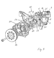
- FIG. 1 shows a pump assembly of a first embodiment in an isometric view of a gas pump 10 of the pump assembly.
- a liquid pump 20 forms in this view a rear part of the pump assembly.
- the pump assembly includes a housing 10 common to both pumps 10 and 20. Such arrangements of pumps are also referred to as a tandem arrangement.
- the common housing comprises a housing part 1, the movable components of the pump assembly, in particular a conveyor of the gas pump 10 and a conveyor of the liquid pump 20, movably supports, and housing parts 2 and 27, of which the housing part 2 a cover of the gas pump 10 and the housing part 27th forms a lid of the liquid pump 20.
- the housing part 1 is integrally molded, suitably cast in one piece. In principle, however, it can also be composed of several pieces instead.
- the housing parts 2 and 27 are each formed in one piece and joined to the housing part 1, for example, as shown in each case by means of a screw connection.
- the gas pump 10 and the liquid pump 20 are designed as rotary pumps.
- the rotary pumps 10 and 20 are arranged coaxially along a common axis of rotation axially one behind the other.
- the housing part 1 is arranged axially centrally.
- the housing part 2 is arranged on the one axial end side and the housing part 27 on the other axial end side of the housing part 1.
- the conveyor of the gas pump 10 comprises a rotatable about the rotation axis conveyor rotor 11 and a single wing 12.
- the conveyor is correspondingly single-leaf.
- the conveyor rotor 11 guides the wing 12 radially displaceable.
- the housing part 1 forms in the region of the gas pump 10 a housing pot, which delimits a delivery chamber 3 on one of the liquid pump 20 axially facing end face and surrounds the circumference.
- With rotary drive of the conveyor rotor 11 of the wing 12 runs in the delivery chamber 3 and divides the delivery chamber 3 in a delivery cell, which increases on a low pressure side of the gas pump 10, and a further delivery cell, which decreases on the high pressure side of the gas pump 10.
- the gas pump 10 can be operated in particular as a vacuum or vacuum pump, for example, to supply a brake booster of a vehicle with negative pressure.
- the brake booster or another or further vacuum unit of the vehicle is connected to the inlet 4 and the aspirated gas, preferably air, is discharged via the outlet 5 into the environment, for example into a crankcase of an internal combustion engine.
- a lubricant serving to lubricate the conveyor 10 is also ejected through the outlet 5.
- FIG. 1 shows the housing part 2 prior to assembly in a position in which the housing part 2 of the facing open end of the housing part 1 is axially opposite and pressed to close the delivery chamber 3 only axially against the housing part 1 and must be firmly connected to this.
- a groove-shaped sealing recess 9 is formed completely circumferentially around the delivery chamber 3.
- a sealing ring is arranged in a shape according to comparable sealing depression, which is elastically pressed in the assembled state of the housing parts 1 and 2 and thereby ensures the required sealing of the sealing joint.
- the sealing joint between the sealing surfaces 6 and 7 is ensured by a sealing liquid located in the sealing 9.
- the sealing recess 9 is filled at least in pump operation with the sealing liquid.
- An elastic sealing ring or other sealing element is not required for sealing the sealing joint 6, 7.
- the housing part 1 has a sealing recess 9 for the sealing liquid.
- a Sealing recess corresponding to the sealing recess 9 instead be provided only in the sealing surface 7 of the housing part 2.
- FIG. 2 shows the pump assembly of the first embodiment in an axial view of the gas pump 10.
- the housing part 2 is joined to the housing part 1, but shown cut in a partial area, so that in this part of the area covered by the housing part 2 in the remaining area sealing surface 6 and sealing recess. 9 are visible.
- the sealing recess 9 is not encapsulated, but connected via a feed with a system from which sealing liquid can be guided into the Dichtveitiefung 9. From the supply sections 15 and 16 can be seen, which connect the sealing recess 9 with an inlet 14 for the sealing liquid.
- the inlet 14 is provided in the housing part 1. When assembling the pump assembly, for example on an internal combustion engine, the inlet 14 is connected to a fluid system leading the sealing liquid.
- the feed 14, 15 and 16 is sealed at the end face of the housing part 1 by the housing part 2 simultaneously with the sealing recess 9.
- the formation of the feed sections 15 and 16 as open to the front side sections facilitates the preparation of the feed 14, 15 and 16.
- the section 15 opens radially adjacent to the sealing recess 9 and is connected via the open end 16 to the sealing recess 9.
- the section 15 may be formed in particular as an axial bore. An oblique hole or another course would be instead also feasible.
- FIG. 3 shows the pump assembly of the first embodiment in an isometric view of the liquid pump 20.
- the liquid pump 20 is like the gas pump 10 of the vane type.
- the liquid pump 20 comprises a multi-leaf conveyor with a rotatable about the common axis of rotation with the gas pump 10 conveyor rotor 21 and a plurality of distributed over the circumference of the conveyor rotor 21 arranged wings 22.
- the liquid pump 20 is in relation to their specific Delivery volume adjustable. It comprises an adjusting ring 23, which is mounted pivotably relative to the housing part 1 in order to be able to adjust an eccentricity of the conveyor 21, 22 and thereby the specific delivery volume of the liquid pump 20.
- a restoring spring 26 exerts on the adjusting ring 23 a restoring force acting in the direction of maximum delivery volume.
- the adjusting ring 23 is acted upon counteracting this restoring force with the conveyed by the liquid pump 20 hydraulic fluid in the direction of a reduction of the specific delivery volume.
- the vanes 22 divide a delivery chamber of the liquid pump 20 into delivery cells, which increase in rotational drive of the conveyor 21, 22 and eccentric position of the adjusting ring 23 relative to the axis of rotation on a low pressure side of the delivery chamber, whereby liquid is sucked into the delivery chamber, and on a high pressure side reduce the delivery chamber again, so that on the high pressure side through an outlet 25, the liquid is ejected under increased pressure.
- the inlet region comprises an inlet 24 of the housing part 1, which in FIG. 1 is recognizable, and in the housing part 1 upstream of the feed chamber located inlet portion 24, in which the return spring 26 is arranged by way of example and from which a chamber inlet leads directly into the feed chamber.
- the outlet region comprises the chamber outlet leading directly from the delivery chamber, furthermore an outlet section 25 formed in the housing part 1 and downstream of this an outlet 25 of the housing part 1.
- the sealing liquid of the gas pump 10 can be, in particular, liquid lubricant, suitably the same lubricant with which the conveyor 11, 12 is lubricated and the delivery cells formed in the delivery chamber 3 of the gas pump 10 are sealed against each other.
- a certain, albeit low permeability of the sealing joint 6, 7 may therefore be present or desired in the direction of the delivery chamber 3.
- the sealing joint 6, 7 may be designed so that in operation of the gas pump 10 due to a prevailing when using a vacuum pump in the delivery chamber 3 negative pressure sealing liquid from the Dichtveitiefung 9 inside, in the delivery chamber 3 penetrates to the mentioned functions, namely the Lubrication of the conveyor 11, 12 and / or the sealing of the conveyor cells and / or cooling, to work in conjunction with otherwise supplied lubricant.
- the liquid pump 20 may in particular be a lubricant pump for supplying an aggregate with a liquid lubricant.
- the liquid pump 20 is a lubricant pump for supplying an internal combustion engine, preferably a drive motor of a vehicle, with liquid lubricant.
- the sealing liquid for sealing the gas pump is the liquid which is conveyed by means of the liquid pump 20.
- the supply 14, 15 and 16 is connected to the fluid system formed by means of the liquid pump 20.
- the sealing recess 9 is connected via the feed 14, 15 and 16 to the high pressure side of the liquid pump 20, so that the liquid pump 20 promotes the sealing liquid via the feed 14, 15 and 16 with pressure in the recess 9.
- the sealing recess 9 can be connected in particular at a point between the filter device and the unit to be supplied, by placing in the flow path of the liquid between the filter device and the unit to be supplied branches off a further feed section which connects the fluid system to the inlet 14 of the feeders 14, 15 and 16.
- the fluid is a lubricant and the gas pump 10 is not or at least not lubricated and / or sealed exclusively with liquid from the sealing recess 9, the same inlet 14 can also serve the lubricant required for the lubrication and sealing, bypassing the Sealing groove 9 to lead in the gas pump 10.
- the same liquid can be used as a control pressure fluid for adjusting the specific delivery volume of the liquid pump 20 by the adjusting ring 23 of the Return spring 26 counteracting the liquid, advantageously purified liquid, is acted upon.
- the pump assembly is rotationally driven via a drive wheel 13. If the pump arrangement is associated with an internal combustion engine, it can be driven, for example, by a crankshaft of the internal combustion engine via the drive wheel 13.
- the drive wheel 13 may be part of a traction mechanism or a gear transmission, in principle also be a friction gear.
- the drive wheel 13 is mechanically coupled to both the conveyor 11, 12 so also with the conveyor 21, 22 and may be rotatably connected in particular with two conveyor rotors 11 and 21.
- the pump assembly may be partially or wholly submerged in a sump or other type of reservoir of liquid, particularly a reservoir of liquid conveyed by the liquid pump 20.
- the pump assembly may be arranged partially or wholly immersed in a lower region, for example on a lower side, an internal combustion engine, in the lubricant sump of the internal combustion engine.
- the arrangement in a liquid reservoir, preferably a lubricant reservoir, is advantageous for the sealing of the gas pump. Due to the prevailing in the pumping operation in the delivery chamber 3 negative pressure can and may be sucked lubricant from the environment, the reservoir, via the sealing joint 6, 7 in the sealing recess 9 and from there into the delivery chamber 3.
- the outside surrounding the gas pump lubricant which also serves as a sealing liquid, effectively prevents ambient air in the area surrounded by the lubricant via the sealing joint 6, 7 is sucked, whereby the tightness of the gas pump and thus their efficiency and flow rate can be improved.
- Said filter device is external with respect to the pump arrangement. It may for example be integrated or mounted on the internal combustion engine.
- the housing outlet 25 of the liquid pump 20 and the inlet 14 leading to the sealing recess 9 of the gas pump 10 are thus connected to one another via the internal combustion engine or a unit comprising the filter device and mounted on the internal combustion engine.
- the sealing recess 9 but also on the feed sections 15 and 16 ( FIG. 2 ) or a supply formed differently within the housing 1, 2, 27 of the pump assembly with the high-pressure side of the liquid pump 20 are in communication to supply the liquid pumped by the liquid pump 20 of the Dichtveitiefung 9 as a sealing liquid.
- FIGS. 4, 5 and 6 show a pump assembly of a second embodiment, which differs from the pump assembly of the first embodiment only with respect to the supply of the sealing liquid in the sealing recess 9.
- the pump arrangement of the second embodiment is shown in an isometric view of the gas pump 10.
- FIG. 5 shows the pump assembly in an axial view of the gas pump 10, wherein the housing part 2 is cut out in a partial region to release the view of the delivery chamber 3 and in particular on the sealing surface 6 and the recess 9 in this sub-area.
- the Figures 1 and 2 of the first embodiment correspond to the FIGS. 4 and 5 the Figures 1 and 2 of the first embodiment.
- the sealing recess 9 is connected to the low pressure side of the liquid pump 20 and is supplied via a formed in or on the housing 1, 2 and 27 feed 17 with the sealing liquid.
- the feed 17 is formed in the embodiment in or on the housing part 1 and opens into the sealing surface 6, in which the sealing recess 9 is formed as in the first embodiment to the delivery chamber 3 completely circumferential.
- the supply 17 is closed together with the sealing recess 9 of the sealing surface 7 of the housing part 2.
- FIG. 5 shows the geometric conditions in the mouth region of the feed 17.
- the feed 17 opens in the sealing surface 6 directly adjacent to the sealing recess 9 radially outward.
- the housing part 1 is bulged to the outside in the region of the feed 17, in particular in the region of the sealing surface 6, in order to provide sufficient surface for sealing the sealing joint in the region of the feed 17 or its mouth.
- FIG. 6 shows the pump assembly of the second embodiment in a longitudinal section, which includes common axis of rotation R for both pumps 10 and 20.
- the pump arrangement can be seen in three parts with the central housing part 1 and the two housing parts 7 and 27 serving as the housing cover. It can also be seen that axially through the housing part 1, in the example also through the housing part 27, one around the Rotary axis R rotatable shaft extending, which forms the conveyor rotor 11 of the gas pump in one piece and on which the conveyor rotor 21 (FIG. FIG. 3 ) of the liquid pump 20 is arranged lubunbeweglich.
- the drive wheel 13 is also rotatably connected to the shaft, so that by rotating driving the drive wheel 13, the shaft and, as a result, both conveyor rotors 11 and 21 are rotated together.
- the housing part 1 forms a rotational sliding bearing for the shaft in a section located axially between the gas pump and the fluid pump.
- the supply 17 extends through the housing part 1, in the second embodiment axially straight, and opens on the low pressure side of the liquid pump 20 in the inlet portion 24 of the inlet portion in which the return spring 26 is arranged.
- the liquid drawn in by the liquid pump 20 is supplied as sealing liquid due to its inflow velocity or kinetic energy through the feed 17 to the sealing depression 9.
- the gas pump 10 is operated as a vacuum pump and there is a connection between the sealing recess 9 and the delivery chamber 3, which allows a small flow of sealing liquid from the sealing recess 9 in the delivery chamber 3, such a suction effect can promote the promotion of the sealing liquid in the sealing recess 9 or possibly also alone effect only.
- the feeder 17 advantageously branches off on the low-pressure side of the liquid pump 20 at a position which is georadically above the level of the liquid which sets when the liquid pump 20 is stationary. In view of the pump geometry of the embodiment, this means that the pump assembly is only partially immersed in compliance with this boundary condition in the liquid.
- the pump arrangement of the second embodiment corresponds to that of the first embodiment, so that reference is made to the remarks on the other hand.
- the housing parts 2 and 27 are each formed as a simple cover, which cover the delivery chamber 3 and the delivery chamber of the liquid pump 20 at each an open axial end side of the housing part 1.
- the housing part 2 not only the front side, but also the peripheral wall of the delivery chamber 3 form.
- the sealing joint 6, 7 would not be in such modifications as in the embodiments of the in FIG. 6 left end face of the delivery chamber 3, but at the right end of the delivery chamber 3 in the then formed there sealing surface of the modified housing part 2 or preferably in the then axially opposite sealing surface of the modified, namely shortened, housing part 1 is arranged.
Landscapes
- Engineering & Computer Science (AREA)
- Mechanical Engineering (AREA)
- General Engineering & Computer Science (AREA)
- Details And Applications Of Rotary Liquid Pumps (AREA)
- Details Of Reciprocating Pumps (AREA)
- Compressor (AREA)
- Applications Or Details Of Rotary Compressors (AREA)
- Compressors, Vaccum Pumps And Other Relevant Systems (AREA)
- Reciprocating Pumps (AREA)
Abstract
Description
- Die Erfindung betrifft die Abdichtung einer Gaspumpe, insbesondere einer Unterdruckpumpe.
- Unterdruckpumpen, wie die Erfindung sie insbesondere betrifft, werden in Fahrzeugen beispielsweise zur Bereitstellung von Unterdruck für einen Bremskraftverstärker eingesetzt. Die Pumpe kann seitlich am Zylinderkopf eines Fahrzeugmotors angeordnet und durch eine Nockenwelle angetrieben werden, wie dies über lange Zeit üblich war. Aufgrund von Bauraumrestriktionen und auch zur Reduzierung der spezifischen Baugröße wird die Unterdruckpumpe in jüngerer Zeit in Tandemanordnung mit einer Schmierölpumpe im Ölsumpf angeordnet. Wegen relativ hoher Anforderungen an die Dichtheit, war es bislang üblich, mittels O-Ring- oder Profilformdichtung zu dichten. Die Dichtung soll verhindern, dass aus der Umgebung Luft angesaugt wird. Bei am Motor außen angebauten Pumpen soll ferner ein Ölaustritt verhindert werden. Bei Anordnung im Ölsumpf ist eine absolute Öldichtheit des Systems nach außen nicht mehr zwingend erforderlich. Die Dichtung dient praktisch nur noch der Vermeidung des Luftsaugens.
- Die Dichtelemente, wie etwa O-Ring- und Profilformdichtungen, werden separat gefertigt und in eine die Förderkammer umschließende Dichtnut eines Gehäuseteils der Gaspumpe eingelegt oder auf eine Stirnseite des Gehäuseteils aufgelegt. Für den Zusammenbau und während des Zusammenbaus werden sie am Gehäuseteil gesichert. Die Dichtelemente verursachen Kosten, die insbesondere in Großserienfertigungen, wie sie in der Fahrzeugfertigung üblich sind, nicht mehr vernachlässigt werden können. Über die Lebensdauer der Pumpe gesehen leidet ferner die Dichtigkeit aufgrund Materialdegradation der Dichtelemente.
- Gaspumpen, die wie von der Erfindung bevorzugt als Flügelzellenpumpen ausgeführt sind, offenbaren beispielsweise die
US 2012/0060683 A , dieUS 3 326 456 A und dieWO 2007/003215 A1 . - Es ist eine Aufgabe der Erfindung, eine Gaspumpe mit einer den Anforderungen der Praxis genügenden, jedoch kostengünstigeren Abdichtung der Förderkammer zu schaffen.
- Die Erfindung geht von einer Gaspumpe aus, die ein erstes Gehäuseteil mit einer Dichtfläche und ein zweites Gehäuseteil ebenfalls mit einer Dichtfläche, ferner eine Förderkammer mit einem Einlass und einem Auslass für ein Gas und eine in der Förderkammer bewegliche Fördereinrichtung zum Fördern des Gases aufweist. Die beiden Gehäuseteile können alleine miteinander die Förderkammer bilden, insbesondere von einem oder mehreren Einlässen und einem oder mehreren Auslässen abgesehen die Förderkammer vollständig umschließen. Grundsätzlich ist es aber auch möglich, dass das erste Gehäuseteil und das zweite Gehäuseteil die Förderkammer erst gemeinsam mit einem oder mehreren weiteren Gehäuseteilen der Gaspumpe umschließen. Eines der beiden Gehäuseteile, beispielsweise das zweite Gehäuseteil, kann insbesondere ein Gehäusedeckel sein, der die Förderkammer an einer Stirnseite abschließt. Die Gehäuseteile sind miteinander gefügt, so dass sie die Förderkammer über einen Kammerumfang zumindest teilweise, vorzugsweise gänzlich umschließen und mit den genannten Dichtflächen unter Bildung einer Dichtfuge aneinander liegen, um die Förderkammer abzudichten. Im gefügten Zustand sind die Dichtflächen vorzugsweise gegeneinander gepresst, beispielsweise indem die Gehäuseteile mittels Schraubverbindung miteinander gefügt sind.
- Nach der Erfindung erstreckt sich in wenigstens einer der Dichtflächen um die Förderkammer eine Dichtvertiefung, die im Betrieb der Gaspumpe mit einer Dichtflüssigkeit gefüllt ist. Bevorzugt ist die Dichtvertiefung vollständig mit der Dichtflüssigkeit gefüllt. Der Füllgrad der Dichtvertiefung ist zumindest so groß, dass durch die in der Dichtvertiefung befindliche Dichtflüssigkeit die Abdichtung der Förderkammer in einem für die praktischen Belange erforderlichen Ausmaß gewährleistet ist. In bevorzugten Ausführungen ist die Dichtvertiefung nur mit der Dichtflüssigkeit gefüllt. Jedenfalls stellt die Dichtflüssigkeit in der Dichtvertiefung erst die Dichtigkeit der Förderkammer über die Dichtfuge der Dichtflächen hinweg sicher.
- Die Dichtvertiefung kann sich insbesondere kontinuierlich über den gesamten Umfang der Förderkammer erstrecken, d.h. über 360°. In Abwandlungen kann sie über den Umfang an einer oder mehreren Stellen lokal unterbrochen sein. Sie kann sich grundsätzlich auch nur über einen Teil des Umfangs, in derartigen Ausführungen allerdings bevorzugt über den überwiegenden Teil des Umfangs erstrecken. Es soll auch nicht ausgeschlossen werden, dass sich das Gehäuseteil, in dem die Dichtvertiefung vorgesehen ist, nur über einen Teil des Umfangs der Förderkammer erstreckt. In Ausführungen, in denen das Gehäuse der Gaspumpe derart geteilt ist, dass erst zwei oder mehr Gehäuseteile zusammen die Förderkammer vollständig, über 360°, umgeben, ist in bevorzugten Ausführungen in jedem dieser Gehäuseteile eine Dichtvertiefung geformt, bevorzugt in solch einer Weise, dass die in den mehreren Gehäuseteilen vorgesehenen Dichtvertiefungen zusammen die Förderkammer über ihren vollständigen Umfang kontinuierlich umgeben, also ineinander übergehen bzw. unterbrechungsfrei aneinander anschließen. Abwandlungen im vorstehend genannten Sinne sind jedoch auch in derartigen Ausführungen möglich.
- Die Dichtvertiefung wird sowohl längs eines der Förderkammer zugewandten inneren Rands als auch längs eines der Förderkammer abgewandten äußeren Rands von der Dichtfläche begrenzt, in der die Dichtvertiefung geformt ist. Die Dichtvertiefung ist mit anderen Worten in einer Stirnansicht auf die Dichtfläche gesehen innerhalb der Dichtfläche geformt, was allerdings nicht ausschließt, dass diese Dichtvertiefung stellenweise mit einem inneren oder einem äußeren Rand der Dichtfläche in Verbindung steht, beispielsweise über einen oder mehrere von der Dichtvertiefung nach innen oder außen abzweigende(n), nutförmige(n) Kanal oder Kanäle. Solch ein Kanal kann beispielsweise der Zuführung der Dichtflüssigkeit in die Dichtvertiefung dienen.
- Durch die Erfindung können der bislang separat gefertigte Dichtring eingespart, die Montage der Gaspumpe vereinfacht und in der Folge Kosten reduziert werden. Bei bisherigen Abdichtungen, bei denen in einer Dichtnut ein Dichtring eingelegt ist, wird die Dichtnut üblicherweise spanend bearbeitet. Eine spanende Bearbeitung kann bei erfindungsgemäßer Dichtvertiefung entfallen. Die Dichtvertiefung kann unmittelbar bei einer Urformung, beispielsweise einem Gießen, geformt oder nachträglich durch Prägen eingeformt werden, wodurch sich die Herstellkosten nochmals reduzieren lassen. Aufgrund der Teilereduzierung verringert sich ferner der Logistik- und Prüfaufwand in der Teileherstellung und der Montage der Gaspumpe.
- Die Gaspumpe kann insbesondere als Unterdruckpumpe ausgeführt und zur Versorgung eines oder mehrerer Aggregate, vorzugsweise eines oder mehrerer Aggregate eines Kraftfahrzeugs, mit Unterdruck verwendet werden oder für solch eine Verwendung vorgesehen sein. Eine Anwendung, auf welche die Erfindung abzielt, ist die einer Vakuumpumpe zur Versorgung eines Bremskranverstärkers oder anderen Aggregats eines Kraftfahrzeugs mit Unterdruck. Die Erfindung ist auf derartige Verwendungen jedoch nicht beschränkt, die Gaspumpe kann grundsätzlich auch zur Versorgung eines oder mehrerer Aggregate mit Druckgas dienen. Bei dem Gas kann es sich um Luft, grundsätzlich aber auch ein anderes Gas handeln.
- Die Gaspumpe kann als Rotationspumpe ausgeführt sein. In derartigen Ausführungen kann die Fördereinrichtung im Ganzen gesehen in der Förderkammer um eine Drehachse drehbar sein oder wenigstens ein in der Förderkammer um eine Drehachse drehbares Förderglied umfassen. Die Fördereinrichtung kann auch mehrere, um voneinander beabstandete Drehachsen drehbare Förderglieder umfassen. Die Gaspumpe kann insbesondere eine Flügelzellenpumpe sein und die Fördereinrichtung entsprechend einen oder mehrere Förderrotoren mit jeweils einem einzigen oder aber mehreren Flügeln umfassen.
- In bevorzugten Ausführungen ist die Dichtvertiefung über eine Zuführung an ein Reservoir oder einen Kreislauf der Dichtflüssigkeit angeschlossen, so dass die Dichtflüssigkeit der Dichtvertiefung im gefügten Zustand der Gehäuseteile zugeführt werden kann. Alternativ kann die Dichtvertiefung aber auch ohne die Möglichkeit der Zuführung von Dichtflüssigkeit dicht geschlossen sein. Der Anschluss der Dichtvertiefung an ein Reservoir oder einen Kreislauf hat jedoch den Vorteil, dass der Dichtvertiefung auch noch nachträglich, d. h. nach dem Zusammenbau der Gaspumpe, Dichtflüssigkeit zugeführt werden kann, beispielsweise zum erstmaligen oder auch wiederholten Befüllen der Dichtvertiefung oder zum Ausgleich von über die Dichtfuge oder durch eine optionale lokale Abführung aus der Dichtvertiefung gedrungene Dichtflüssigkeit.
- Die Dichtflüssigkeit kann eine Flüssigkeit sein, die in der Umgebung der Gaspumpe für einen anderen Zweck eingesetzt wird, beispielsweise als Arbeitsflüssigkeit, wie etwa ein Hydrauliköl, eines anderen Aggregats. Vorzugsweise bildet ein flüssiges Schmiermittel die Dichtflüssigkeit. Dabei kann es sich um das gleiche Schmiermittel handeln, das auch der Schmierung der Fördereinrichtung und/oder Abdichtung von in der Förderkammer gebildeten Förderzellen dient. Ist die Gaspumpe einer Brennkraftmaschine eines Kraftfahrzeugs, Flugzeugs oder Wasserfahrzeugs zugeordnet, kann insbesondere ein der Schmierung der Brennkraftmaschine dienendes Schmiermittel in weiterer Funktion auch die Dichtflüssigkeit bilden. Bildet ein flüssiges Schmiermittel die Dichtflüssigkeit, kann die Dichtflüssigkeit vorteilhafterweise der Schmierung der Fördereinrichtung und/oder Abdichtungszwecken, beispielsweise der Abdichtung optional innerhalb der Förderkammer gebildeter Förderzellen dienen. Um wenigstens eine dieser Funktionen erfüllen zu können, kann zwischen der Dichtvertiefung und der Förderkammer eine Verbindung bestehen, derart, dass zunächst in der Dichtvertiefung als Dichtflüssigkeit dienendes Schmiermittel aus der Dichtvertiefung in die Förderkammer dringen kann. Hierfür können beispielsweise im Bereich der Dichtfuge zwischen der Dichtvertiefung und der Förderkammer eine oder mehrere lokale Verbindungen bzw. Abführungen vorgesehen oder der gesamte Bereich der Dichtfuge, der sich zwischen der Dichtvertiefung und der Förderkammer befindet, gleichmäßig mit einer gewissen Undichtigkeit ausgeführt sein, um einen geringen Fluss von Dichtflüssigkeit, respektive Schmiermittel, aus der Dichtvertiefung in die Förderkammer zuzulassen. Ein derartiger Fluss in Richtung Förderkammer wird in Ausführungen, in denen die Gaspumpe wie bevorzugt eine Unterdruckpumpe ist, wegen des im Betrieb der Gaspumpe in der Förderkammer herrschenden Unterdrucks begünstigt.
- Gegenstand der Erfindung ist auch eine Kombination der Gaspumpe mit einer Flüssigkeitspumpe, die der Versorgung eines Aggregats mit einer Flüssigkeit, beispielsweise einer Arbeitsflüssigkeit oder einem flüssigen Schmiermittel, dient, wobei diese Flüssigkeit in weiterer Funktion auch die Dichtflüssigkeit für die Gaspumpe bildet. Bei der Flüssigkeitspumpe kann es sich insbesondere um eine Schmiermittelpumpe zur Versorgung einer Brennkraftmaschine oder eines anderen Aggregats mit flüssigem Schmiermittel dienen. Die Flüssigkeitspumpe weist eine Förderkammer und die Förderkammer auf einer Niederdruckseite der Flüssigkeitspumpe einen Einlass und auf einer Hochdruckseite der Flüssigkeitspumpe einen Auslass für die Flüssigkeit auf. Die Flüssigkeitspumpe weist ferner eine antreibbare Fördereinrichtung auf, die bei einem Antrieb in der Förderkammer eine Förderbewegung ausführen kann, durch die die Flüssigkeit vom Einlass zum Auslass der Förderkammer gefördert wird. Bei dem Einlass kann es sich um einen Einlass der Flüssigkeitspumpe stromauf der Förderkammer oder einen Einlass unmittelbar in die Förderkammer handeln. Bei dem Auslass kann es sich um einen Auslass unmittelbar der Förderkammer oder einen Auslass der Flüssigkeitspumpe stromabwärts der Förderkammer handeln. In der Kombination von Gas- und Flüssigkeitspumpe kann vorteilhafterweise eine Zuführung der bereits zuvor erwähnten Art vorgesehen sein und die Dichtvertiefung der Gaspumpe mit der Niederdruckseite oder der Hochdruckseite der Flüssigkeitspumpe verbinden.
- Die Flüssigkeitspumpe weist ein Gehäuseteil auf, das eine oder mehrere Kammerwände der Förderkammer der Flüssigkeitspumpe bildet. Eines der Gehäuseteile der Gaspumpe kann gleichzeitig auch dieses Gehäuseteil der Flüssigkeitspumpe bilden. Das betreffende Gehäuseteil kann insbesondere die Dichtfläche mit der Dichtveitiefung zum Abdichten der Förderkammer der Gaspumpe aufweisen.
- Handelt es sich bei der Gaspumpe und der Flüssigkeitspumpe um Rotationspumpen, so dass die Fördereinrichtung der Gaspumpe und auch die Fördereinrichtung der Flüssigkeitspumpe jeweils wenigstens ein um eine Drehachse drehbares Förderglied aufweisen, ist es ferner vorteilhaft, wenn diese Förderglieder um eine gemeinsame Drehachse drehbar gelagert sind. Die wenigstens zwei drehbaren Förderglieder können einander zwar grundsätzlich umgeben, bevorzugter sind sie jedoch coaxial nebeneinander angeordnet. Das wenigstens eine drehbewegliche Förderglied der Gaspumpe und das wenigstens eine drehbewegliche Förderglied der Flüssigkeitspumpe können relativ zueinander drehbeweglich sein, in bevorzugten Ausführungen sind sie jedoch drehunbeweglich miteinander verbunden. Sie werden vorzugsweise über ein Antriebsrad gemeinsam angetrieben. Dabei können sie mittels eines Getriebes gekoppelt sein. Sie können insbesondere auf einer gemeinsamen Welle angeordnet sein. In derartigen Ausführungen können diese Förderglieder mit der gemeinsamen Welle jeweils drehmomentfest gefügt sein. Es kann auch eines der Förderglieder, entweder ein Förderrotor der Gaspumpe oder ein Förderrotor der Flüssigkeitspumpe, mit der Welle in einem Stück geformt und nur der jeweils andere Förderrotor mit der Welle drehunbeweglich verbunden sein. Grundsätzlich sind auch Ausführungen denkbar, in denen die Welle sowohl einen Förderrotor der Gaspumpe als auch einen Förderrotor der Flüssigkeitspumpe in einem Stück bildet, allerdings wird dies in vielen Ausführungen nur bei einem in axialer Richtung geteilten Gehäuse realisierbar sein.
- Falls eine Zuführung vorgesehen ist, die die Dichtvertiefung der Gaspumpe mit dem System verbindet, in dem die Flüssigkeitspumpe die Flüssigkeit fördert, kann die Zuführung in ersten Ausführungen auf der Hochdruckseite der Flüssigkeitspumpe abzweigen, so dass von der Flüssigkeitspumpe geförderte Flüssigkeit von der Hochdruckseite in die Dichtvertiefung gelangen kann. Unter der Hochdruckseite der Flüssigkeitspumpe versteht die Erfindung denjenigen Teil des Systems, der sich von der Hochdruckseite der Förderkammer der Flüssigkeitspumpe bis zu einer am weitesten stromabwärts gelegenen, von der Flüssigkeitspumpe mit der Flüssigkeit zu versorgenden Stelle des Systems erstreckt. Die Zuführung für die Dichtvertiefung kann zwar grundsätzlich noch unmittelbar auf der Hochdruckseite der Förderkammer der Flüssigkeitspumpe abzweigen, bevorzugter zweigt die Zuführung jedoch stromabwärts der Förderkammer ab. Ist der Flüssigkeitspumpe eine Filtereinrichtung zur Reinigung der geförderten Flüssigkeit nachgeschaltet, wie dies üblich ist, zweigt die Zuführung für die Dichtvertiefung vorteilhafterweise stromabwärts der Filtereinrichtung ab. Von Vorteil ist, wenn die Zuführung stromaufwärts von dem mit der Flüssigkeit zu versorgenden Aggregat, vorzugsweise stromaufwärts von einer im Strömungsweg nach der Filtereinrichtung ersten Stelle des Systems abzweigt, die mit der Flüssigkeit zu versorgen ist. Je reiner die Flüssigkeit ist, die der Dichtvertiefung zugeführt wird, desto günstiger sind die Verhältnisse, insbesondere in Ausführungen, in denen die Dichtflüssigkeit aus der Dichtvertiefung in die Förderkammer der Gaspumpe gelangen kann. Für kurze Strömungswege ist es günstig, wenn die Zuführung nahe bei der Flüssigkeitspumpe oder nahe bei der Förderkammer abzweigt.
- In zweiten Ausführungen, in denen die Dichtvertiefung an das Flüssigkeitssystem der Flüssigkeitspumpe angeschlossen ist, zweigt die Zuführung auf der Niederdruckseite der Flüssigkeitspumpe ab. Die Niederdruckseite der Flüssigkeitspumpe umfasst den stromaufwärts von der Flüssigkeitspumpe gelegenen Abschnitt des Flüssigkeitssystems. Die Niederdruckseite der Flüssigkeitspumpe erstreckt sich von der Niederdruckseite der Förderkammer bis zu einer Stelle des Flüssigkeitssystems, die stromabwärts aller Verbrauchsstellen des Flüssigkeitssystems liegt und von der aus die Flüssigkeitspumpe die Flüssigkeit ansaugt. Dies ist in den meisten Anwendungen ein Flüssigkeitsreservoir wie etwa ein Flüssigkeitssumpf. In bevorzugten Ausführungen zweigt die Zuführung stromaufwärts von der Förderkammer der Flüssigkeitspumpe ab. Die Zuführung kann insbesondere noch innerhalb eines Gehäuses der Flüssigkeitspumpe abzweigen.
- In Ausführungen, in denen die Gaspumpe und die Flüssigkeitspumpe ein gemeinsames Gehäuse aufweisen, kann sich die Zuführung für die Dichtvertiefung in diesem gemeinsamen Gehäuse oder an dem Gehäuse befinden, so dass ein in Bezug auf das gemeinsame Gehäuse externer Anschluss zur Versorgung der Dichtvertiefung nicht erforderlich ist. In Ausführungen, in denen die Zuführung auf der Hochdruckseite der Flüssigkeitspumpe stromabwärts von einer der Reinigung der Flüssigkeit dienenden Filtereinrichtung abzweigt, bedeutet dies, dass die Filtereinrichtung in derartigen Ausführungen ebenfalls im oder am gemeinsamen Gehäuse der Pumpen angeordnet ist. Es kann jedoch auch vorteilhaft sein, die Flüssigkeit zunächst aus dem gemeinsamen Gehäuse heraus zu einer extern angeordneten Filtereinrichtung zu führen und die Flüssigkeit auf der Hochdruckseite der Flüssigkeitspumpe in Bezug auf das gemeinsame Pumpengehäuse extern abzuzweigen und wieder zurück in das Gehäuse und zur Dichtvertiefung zu führen.
- Eine vorteilhafte Situation ergibt sich, wenn die Gaspumpe zumindest teilweise in Flüssigkeit, wie etwa ein flüssiges Schmiermittel, eingetaucht ist und die Flüssigkeit die mittels der Dichtvertiefung abgedichtete Dichtfuge an einer von der Förderkammer der Gaspumpe abgewandten Außenseite zumindest teilweise umgibt. Die umgebende Flüssigkeit sorgt im eingetauchten Umfangsbereich der Dichtfuge für eine zusätzliche äußere Abdichtung. Besonders vorteilhaft ist, wenn es sich bei der umgebenden Flüssigkeit um die gleiche Flüssigkeit wie die Dichtflüssigkeit handelt, ein Eindringen von umgebender Flüssigkeit in die Dichtvertiefung also bis zu einem gewissen Ausmaß keine negativen Auswirkungen hat. Umgebende Flüssigkeit kann beispielsweise eindringen, wenn die Gaspumpe als Unterdruckpumpe verwendet wird und der in der Förderkammer sich einstellende Unterdruck eine bis in die Dichtfuge reichende Sogwirkung entfaltet. In Ausführungen, in denen die Gaspumpe zumindest über einen Teil des Umfangs der Dichtfuge in Flüssigkeit eingetaucht ist, ist es vorteilhaft, wenn die umgebende Flüssigkeit ein Schmiermittel ist, das sich zur Schmierung der Fördereinrichtung und/oder Abdichtung der Förderkammer der Gaspumpe oder von in der Förderkammer gebildeten Förderzellen eignet.
- Die Erfindung betrifft nicht nur eine Gaspumpe mit erfindungsgemäßer Flüssigkeitsdichtung alleine und eine Pumpenanordnung, in der die Gaspumpe mit einer Flüssigkeitspumpe der geschilderten Art kombiniert ist, vorzugsweise in einem gemeinsamen Gehäuse. Die Erfindung betrifft auch eine Brennkraftmaschine mit einer montierten Gaspumpe oder Pumpenanordnung der geschilderten Art sowie ferner ein Fahrzeug, vorzugsweise ein Kraftfahrzeug, mit einer Brennkraftmaschine mit einer montierten Gaspumpe oder Pumpenanordnung der geschilderten Art. Die Brennkraftmaschine kann insbesondere einen Antriebsmotor des Fahrzeugs bilden.
- Vorteilhafte Merkmale werden auch in den Unteransprüchen und den Kombinationen der Unteransprüche beschrieben.
- Nachfolgend wird die Erfindung anhand von Ausführungsbeispielen erläutert. An den Ausführungsbeispielen offenbar werdende Merkmale bilden jeweils einzeln und in jeder Merkmalskombination die Gegenstände der Ansprüche und auch die vorstehend diskutierten Ausführungen vorteilhaft weiter. Es zeigen:
- Figur 1
- eine Pumpenanordnung mit einer Gaspumpe eines ersten Ausführungsbeispiels in einer isometrischen Sicht auf die Gaspumpe,
- Figur 2
- die Pumpenanordnung des ersten Ausführungsbeispiels in einer axialen Teilansicht auf eine Stirnseite der Gaspumpe,
- Figur 3
- die Pumpenanordnung des ersten Ausführungsbeispiels in einer isometrischen Sicht auf eine Flüssigkeitspumpe der Anordnung,
- Figur 4
- eine Pumpenanordnung mit einer Gaspumpe eines zweiten Ausführungsbeispiels in einer isometrischen Sicht auf die Gaspumpe,
- Figur 5
- die Pumpenanordnung des zweiten Ausführungsbeispiels in einer axialen Teilansicht auf eine Stirnseite der Gaspumpe, und
- Figur 6
- die Pumpenanordnung des zweiten Ausführungsbeispiels in einem Längsschnitt.
-
Figur 1 zeigt eine Pumpenanordnung eines ersten Ausführungsbeispiels in einer isometrischen Sicht auf eine Gaspumpe 10 der Pumpenanordnung. Eine Flüssigkeitspumpe 20 bildet in dieser Sicht einen hinteren Teil der Pumpenanordnung. Die Pumpenanordnung umfasst ein für beide Pumpen 10 und 20 gemeinsames Gehäuse. Derartige Anordnungen von Pumpen bezeichnet man auch als Tandemanordnung. Das gemeinsame Gehäuse umfasst ein Gehäuseteil 1, das bewegliche Komponenten der Pumpenanordnung, insbesondere eine Fördereinrichtung der Gaspumpe 10 und eine Fördereinrichtung der Flüssigkeitspumpe 20, beweglich lagert, und Gehäuseteile 2 und 27, von denen das Gehäuseteil 2 einen Deckel der Gaspumpe 10 und das Gehäuseteil 27 einen Deckel der Flüssigkeitspumpe 20 bildet. Das Gehäuseteil 1 ist einstückig geformt, zweckmäßigerweise in einem Stück gegossen. Es kann grundsätzlich stattdessen aber auch aus mehreren Stücken gefügt sein. Die Gehäuseteile 2 und 27 sind jeweils in einem Stück geformt und mit dem Gehäuseteil 1 gefügt, beispielsweise wie dargestellt jeweils mittels Schraubverbindung. - Die Gaspumpe 10 und die Flüssigkeitspumpe 20 sind als Rotationspumpen ausgeführt. Die Rotationspumpen 10 und 20 sind coaxial längs einer gemeinsamen Drehachse axial hintereinander angeordnet. Das Gehäuseteil 1 ist axial zentral angeordnet. Das Gehäuseteil 2 ist an der einen axialen Stirnseite und das Gehäuseteil 27 an der anderen axialen Stirnseite des Gehäuseteils 1 angeordnet.
- Die Fördereinrichtung der Gaspumpe 10 umfasst einen um die Drehachse drehbeweglichen Förderrotor 11 und einen einzigen Flügel 12. Die Fördereinrichtung ist entsprechend einflügelig. Der Förderrotor 11 führt den Flügel 12 radial verschieblich. Das Gehäuseteil 1 bildet im Bereich der Gaspumpe 10 einen Gehäusetopf, der eine Förderkammer 3 an einer der Flüssigkeitspumpe 20 axial zugewandten Stirnseite begrenzt und über den Umfang umgibt. Bei Drehantrieb des Förderrotors 11 läuft der Flügel 12 in der Förderkammer 3 um und teilt die Förderkammer 3 in eine Förderzelle, die sich auf einer Niederdruckseite der Gaspumpe 10 vergrößert, und eine weitere Förderzelle, die sich auf der Hochdruckseite der Gaspumpe 10 verkleinert. Aufgrund der Vergrößerung der Förderzelle wird Gas auf der Niederdruckseite durch einen Einlass 4 in die sich vergrößernde Förderzelle gesaugt und anschließend bei Verkleinerung der Förderzelle auf der Hochdruckseite durch einen Auslass 5 ausgestoßen. Die Gaspumpe 10 kann insbesondere als Unterdruck- oder Vakuumpumpe betrieben werden, um beispielsweise einen Bremskraftverstärker eines Fahrzeugs mit Unterdruck zu versorgen. In solch einer Verwendung ist der Bremskraftverstärker oder ein anderes oder weiteres mit Unterdruck zu versorgendes Aggregat des Fahrzeugs an den Einlass 4 angeschlossen, und das angesaugte Gas, vorzugsweise Luft, wird über den Auslass 5 in die Umgebung ausgestoßen, beispielsweise in ein Kurbelgehäuse eines Verbrennungsmotors. Dabei wird gleichzeitig auch ein der Schmierung der Fördereinrichtung 10 dienendes Schmiermittel durch den Auslass 5 ausgestoßen.
- Das Gehäuseteil 2 verschließt die Förderkammer 3 an der einen Stirnseite.
Figur 1 zeigt das Gehäuseteil 2 vor der Montage in einer Position, in der das Gehäuseteil 2 der zugewandten offenen Stirnseite des Gehäuseteils 1 axial gegenüberliegt und zum Verschließen der Förderkammer 3 nur noch axial gegen das Gehäuseteil 1 gedrückt und fest mit diesem verbunden werden muss. Im gefügten Zustand liegen eine dem Gehäuseteil 2 axial zugewandte Dichtfläche 6 des Gehäuseteils 1 und eine dem Gehäuseteil 1 axial zugewandte Dichtfläche 7 des Gehäuseteils 2 axial aneinander und bilden eine um die Förderkammer 3 erstreckte Dichtfuge, um die Förderkammer 3 über ihren Umfang abzudichten. In der Dichtfläche 6 ist um die Förderkammer 3 vollständig umlaufend eine nutförmige Dichtvertiefung 9 geformt. Bei herkömmlichen Gaspumpen ist in einer der Form nach vergleichbaren Dichtvertiefung ein Dichtring angeordnet, der im gefügten Zustand der Gehäuseteile 1 und 2 elastisch gepresst wird und dadurch für die erforderliche Abdichtung der Dichtfuge sorgt. Anders als bei herkömmlichen Abdichtungen wird die Dichtfuge zwischen den Dichtflächen 6 und 7 jedoch durch eine in der Dichtveitiefung 9 befindliche Dichtflüssigkeit gewährleistet. Die Dichtvertiefung 9 ist zumindest im Pumpenbetrieb mit der Dichtflüssigkeit gefüllt. Eines elastischen Dichtrings oder anderen Dichtelements bedarf es zur Abdichtung der Dichtfuge 6, 7 nicht. Im Ausführungsbeispiel weist das Gehäuseteil 1 eine Dichtvertiefung 9 für die Dichtflüssigkeit auf. In einer Modifikation könnte eine Dichtvertiefung entsprechend der Dichtvertiefung 9 stattdessen auch nur in der Dichtfläche 7 des Gehäuseteils 2 vorgesehen sein. Grundsätzliche wäre es auch denkbar, in beiden Dichtflächen 6 und 7 jeweils eine Dichtveitiefung vorzusehen, die im gefügten Zustand in Überdeckung oder nebeneinander oder in Umfangsrichtung auch nur hintereinander erstreckt und im Pumpenbetrieb mit Dichtflüssigkeit gefüllt sind. -
Figur 2 zeigt die Pumpenanordnung des ersten Ausführungsbeispiels in einer axialen Sicht auf die Gaspumpe 10. Das Gehäuseteil 2 ist mit dem Gehäuseteil 1 gefügt, in einem Teilbereich jedoch ausgeschnitten dargestellt, so dass in diesem Teilbereich die vom Gehäuseteil 2 im übrigen Bereich abgedeckten Dichtfläche 6 und Dichtvertiefung 9 sichtbar sind. Die Dichtvertiefung 9 ist nicht gekapselt, sondern über eine Zuführung mit einem System verbunden, aus dem Dichtflüssigkeit in die Dichtveitiefung 9 geführt werden kann. Von der Zuführung sind Abschnitte 15 und 16 erkennbar, welche die Dichtvertiefung 9 mit einem Einlass 14 für die Dichtflüssigkeit verbinden. Der Einlass 14 ist im Gehäuseteil 1 vorgesehen. Bei der Montage der Pumpenanordnung, beispielsweise an einer Brennkraftmaschine, wird der Einlass 14 an ein die Dichtflüssigkeit führendes Flüssigkeitssystem angeschlossen. Die Zuführung 14, 15 und 16 wird an der Stirnseite des Gehäuseteils 1 durch das Gehäuseteil 2 gleichzeitig mit der Dichtvertiefung 9 abgedichtet. Die Ausbildung der Zuführabschnitte 15 und 16 als zur Stirnseite offene Abschnitte erleichtert die Herstellung der Zuführung 14, 15 und 16. Der Abschnitt 15 mündet radial neben der Dichtvertiefung 9 und ist über den zur Stirnseite offenen Abschnitt 16 mit der Dichtvertiefung 9 verbunden. In einer Modifikation kann der Abschnitt 15 aber auch radial mit der Dichtvertiefung 9 überlappen und dementsprechend der Verbindungsabschnitt 16 entfallen. Der Abschnitt 15 kann insbesondere als axiale Bohrung gebildet sein. Eine schräge Bohrung oder ein anderer Verlauf wären stattdessen aber ebenfalls realisierbar. -
Figur 3 zeigt die Pumpenanordnung des ersten Ausführungsbeispiels in einer isometrischen Sicht auf die Flüssigkeitspumpe 20. Die Flüssigkeitspumpe 20 ist wie die Gaspumpe 10 vom Flügelzellentyp. Im Unterschied zur Gaspumpe 10 umfasst die Flüssigkeitspumpe 20 eine mehrflügelige Fördereinrichtung mit einem um die mit der Gaspumpe 10 gemeinsame Drehachse drehbaren Förderrotor 21 und mehreren über den Umfang des Förderrotors 21 verteilt angeordneten Flügeln 22. Die Flüssigkeitspumpe 20 ist in Bezug auf ihr spezifisches Fördervolumen verstellbar. Sie umfasst einen Stellring 23, der relativ zum Gehäuseteil 1 schwenkbeweglich gelagert ist, um eine Exzentrizität der Fördereinrichtung 21, 22 und dadurch das spezifische Fördervolumen der Flüssigkeitspumpe 20 verstellen zu können. Eine Rückstellfeder 26 übt auf den Stellring 23 eine in Richtung auf maximales Fördervolumen wirkende Rückstellkraft aus. Der Stellring 23 wird dieser Rückstellkraft entgegenwirkend mit der von der Flüssigkeitspumpe 20 geförderten Druckflüssigkeit in Richtung einer Verringerung des spezifischen Fördervolumens beaufschlagt. Die Flügel 22 unterteilen eine Förderkammer der Flüssigkeitspumpe 20 in Förderzellen, die sich bei einem Drehantrieb der Fördereinrichtung 21, 22 und exzentrischer Stellung des Stellrings 23 relativ zur Drehachse auf einer Niederdruckseite der Förderkammer vergrößern, wodurch Flüssigkeit in die Förderkammer gesogen wird, und auf einer Hockdruckseite der Förderkammer wieder verkleinern, so dass auf der Hochdruckseite durch einen Auslass 25 die Flüssigkeit unter erhöhtem Druck ausgestoßen wird. InFigur 3 sind auf der Niederdruckseite der Flüssigkeitspumpe 20 der gesamte Einlassbereich mit 24 und auf der Hochdruckseite der gesamte Auslassbereich mit 25 bezeichnet. Der Einlassbereich umfasst einen Einlass 24 des Gehäuseteils 1, der inFigur 1 erkennbar ist, und einen im Gehäuseteil 1 stromaufwärts von der Förderkammer gelegenen Einlassabschnitt 24, in dem beispielhaft die Rückstellfeder 26 angeordnet ist und von dem ein Kammereinlass unmittelbar in die Förderkammer führt. Der Auslassbereich umfasst den unmittelbar aus der Förderkammer führenden Kammerauslass, ferner einen im Gehäuseteil 1 gebildeten Auslassabschnitt 25 und stromabwärts hiervon einen Auslass 25 des Gehäuseteils 1. - Bei der Dichtflüssigkeit der Gaspumpe 10 kann es sich insbesondere um flüssiges Schmiermittel handeln, zweckmäßigerweise das gleiche Schmiermittel, mit dem die Fördereinrichtung 11, 12 geschmiert und die in der Förderkammer 3 der Gaspumpe 10 gebildeten Förderzellen gegeneinander abgedichtet werden. Eine gewisse, wenngleich geringe Durchlässigkeit der Dichtfuge 6, 7 kann daher in Richtung zur Förderkammer 3 vorhanden oder auch gewünscht sein. Die Dichtfuge 6, 7 kann so gestaltet sein, dass im Betrieb der Gaspumpe 10 wegen eines bei Verwendung als Unterdruckpumpe in der Förderkammer 3 herrschenden Unterdrucks Dichtflüssigkeit aus der Dichtveitiefung 9 nach innen, in die Förderkammer 3 dringt, um dort die genannten Funktionen, nämlich die Schmierung der Fördereinrichtung 11, 12 und/oder die Abdichtung der Förderzellen und/oder eine Kühlung, im Zusammenwirken mit anderweitig zugeführtem Schmiermittel zu bewirken. Grundsätzlich ist alternativ auch denkbar, Schmierung und Abdichtung allein durch die Dichtflüssigkeit zu bewirken, die aus der Dichtvertiefung 9 in die Förderkammer 3 dringt. Bevorzugt wird jedoch zumindest zur Schmierung der Fördereinrichtung 11, 12 Schmiermittel anderweitig zugeführt, beispielsweise zentral über ein Drehlager des Förderrotors 11.
- Die Flüssigkeitspumpe 20 kann insbesondere eine Schmiermittelpumpe zur Versorgung eines Aggregats mit einem flüssigen Schmiermittel sein. In bevorzugten Verwendungen ist die Flüssigkeitspumpe 20 eine Schmiermittelpumpe zur Versorgung einer Brennkraftmaschine, vorzugsweise eines Antriebsmotors eines Fahrzeugs, mit flüssigem Schmiermittel.
- In einer vorteilhaften Kombination handelt es sich bei der Dichtflüssigkeit zum Abdichten der Gaspumpe um die Flüssigkeit, die mittels der Flüssigkeitspumpe 20 gefördert wird. In derartigen Ausführungen ist die Zuführung 14, 15 und 16 an das mittels der Flüssigkeitspumpe 20 gebildete Flüssigkeitssystem angeschlossen. Im ersten Ausführungsbeispiel ist die Dichtvertiefung 9 über die Zuführung 14, 15 und 16 an die Hochdruckseite der Flüssigkeitspumpe 20 angeschlossen, so dass die Flüssigkeitspumpe 20 die Dichtflüssigkeit über die Zuführung 14, 15 und 16 mit Druck in die Vertiefung 9 fördert. Ist zwischen der Flüssigkeitspumpe 20 und dem zu versorgenden Aggregat eine Filtereinrichtung zum Reinigen der von der Flüssigkeitspumpe 20 geförderten Flüssigkeit angeordnet, kann die Dichtvertiefung 9 insbesondere an einer Stelle zwischen der Filtereinrichtung und dem zu versorgenden Aggregat angeschlossen sein, indem im Strömungsweg der Flüssigkeit zwischen der Filtereinrichtung und dem zu versorgenden Aggregat ein weiterer Zuführabschnitt abzweigt, der das Flüssigkeitssystem mit dem Einlass 14 der Zuführung 14, 15 und 16 verbindet. Handelt es sich bei der Flüssigkeit um ein Schmiermittel und wird die Gaspumpe 10 nicht oder zumindest nicht ausschließlich mit Flüssigkeit aus der Dichtvertiefung 9 geschmiert und/oder abgedichtet, kann der gleiche Einlass 14 auch dazu dienen das für die Schmierung und Abdichtung benötigte Schmiermittel unter Umgehung der Dichtvertiefung 9 in die Gaspumpe 10 zu führen. Ferner kann die gleiche Flüssigkeit als Steuerdruckflüssigkeit zur Verstellung des spezifischen Fördervolumens der Flüssigkeitspumpe 20 verwendet werden, indem der Stellring 23 der Rückstellfeder 26 entgegenwirkend mit der Flüssigkeit, vorteilhafterweise gereinigter Flüssigkeit, beaufschlagt wird.
- Die Pumpenanordnung wird über ein Antriebsrad 13 drehangetrieben. Ist die Pumpenanordnung einer Brennkraftmaschine zugeordnet, kann sie beispielsweise von einer Kurbelwelle der Brennkraftmaschine über das Antriebsrad 13 angetrieben werden. Das Antriebsrad 13 kann Bestandteil eines Zugmittelgetriebes oder auch eines Zahnradgetriebes, grundsätzlich auch eines Reibradgetriebes sein. Das Antriebsrad 13 ist sowohl mit der Fördereinrichtung 11, 12 also auch mit der Fördereinrichtung 21, 22 mechanisch gekoppelt und kann insbesondere mit beiden Förderrotoren 11 und 21 drehunbeweglich verbunden sein.
- Die Pumpenanordnung kann teilweise oder gänzlich in einem Sumpf oder andersartigem Reservoir einer Flüssigkeit eingetaucht sein, insbesondere in ein Reservoir der Flüssigkeit die von der Flüssigkeitspumpe 20 gefördert wird. So kann die Pumpenanordnung in einem unteren Bereich, beispielsweise an einer Unterseite, einer Brennkraftmaschine, im Schmiermittelsumpf der Brennkraftmaschine teilweise oder gänzlich eingetaucht angeordnet sein. Die Anordnung in einem Flüssigkeitsreservoir, vorzugsweise Schmiermittelreservoir, ist für die Abdichtung der Gaspumpe vorteilhaft. Aufgrund des im Pumpenbetrieb in der Förderkammer 3 herrschenden Unterdrucks kann und darf Schmiermittel aus der Umgebung, dem Reservoir, über die Dichtfuge 6, 7 in die Dichtvertiefung 9 und von dort in die Förderkammer 3 gesogen werden. Das die Gaspumpe außen umgebende Schmiermittel, das gleichzeitig auch als Dichtflüssigkeit dient, verhindert wirkungsvoll, dass Umgebungsluft in dem vom Schmiermittel umgebenen Bereich über die Dichtfuge 6, 7 angesaugt wird, wodurch die Dichtigkeit der Gaspumpe und somit deren Wirkungsgrad und Förderleistung verbessert werden können.
- Die genannte Filtereinrichtung ist in Bezug auf die Pumpenanordnung extern. Sie kann beispielsweise an der Brennkraftmaschine integriert oder montiert angeordnet sein. Der Gehäuseauslass 25 der Flüssigkeitspumpe 20 und der zur Dichtvertiefung 9 führende Einlass 14 der Gaspumpe 10 sind somit über die Brennkraftmaschine oder eine an der Brennkraftmaschine montierte, die Filtereinrichtung umfassende Einheit miteinander verbunden. Alternativ kann die Dichtvertiefung 9 aber auch über die Zuführabschnitte 15 und 16 (
Figur 2 ) oder eine anders gebildete Zuführung innerhalb des Gehäuses 1, 2, 27 der Pumpenanordnung mit der Hochdruckseite der Flüssigkeitspumpe 20 in Verbindung stehen, um die von der Flüssigkeitspumpe 20 geförderte Flüssigkeit der Dichtveitiefung 9 als Dichtflüssigkeit zuzuführen. - Die
Figuren 4, 5 und6 zeigen eine Pumpenanordnung eines zweiten Ausführungsbeispiels, die sich von der Pumpenanordnung des ersten Ausführungsbeispiels nur in Bezug auf die Zuführung der Dichtflüssigkeit in die Dichtvertiefung 9 unterscheidet. InFigur 4 ist die Pumpenanordnung des zweiten Ausführungsbeispiels in einer isometrischen Sicht auf die Gaspumpe 10 dargestellt.Figur 5 zeigt die Pumpenanordnung in einer axialen Sicht auf die Gaspumpe 10, wobei das Gehäuseteil 2 in einem Teilbereich ausgeschnitten ist, um den Blick auf die Förderkammer 3 und insbesondere auf die Dichtfläche 6 und die Vertiefung 9 in diesem Teilbereich freizugeben. Insoweit entsprechen dieFiguren 4 und 5 denFiguren 1 und 2 des ersten Ausführungsbeispiels. - Im Unterschied zum ersten Ausführungsbeispiel ist die Dichtvertiefung 9 an die Niederdruckseite der Flüssigkeitspumpe 20 angeschlossen und wird über eine im oder am Gehäuse 1, 2 und 27 geformte Zuführung 17 mit der Dichtflüssigkeit versorgt. Die Zuführung 17 ist im Ausführungsbeispiel im oder am Gehäuseteil 1 geformt und mündet in der Dichtfläche 6, in der auch die Dichtvertiefung 9 wie im ersten Ausführungsbeispiel um die Förderkammer 3 vollständig umlaufend geformt ist. Im gefügten Zustand der Gehäuseteile 1 und 2 wird die Zuführung 17 zusammen mit der Dichtvertiefung 9 von der Dichtfläche 7 des Gehäuseteils 2 verschlossen.
-
Figur 5 zeigt die geometrischen Verhältnisse im Mündungsbereich der Zuführung 17. Die Zuführung 17 mündet in der Dichtfläche 6 unmittelbar an die Dichtvertiefung 9 radial außen angrenzend. Das Gehäuseteil 1 ist nach außen im Bereich der Zuführung 17 ausgebaucht, insbesondere im Bereich der Dichtfläche 6, um auch im Bereich der Zuführung 17 bzw. deren Mündung außen ausreichend Fläche zum Abdichten der Dichtfuge bereitzustellen. -
Figur 6 zeigt die Pumpenanordnung des zweiten Ausführungsbeispiels in einem Längsschnitt, der für beide Pumpen 10 und 20 gemeinsame Drehachse R beinhaltet. Das Gehäuse der Pumpenanordnung ist wie insbesondere in diesem Schnitt erkennbar dreiteilig mit dem zentralen Gehäuseteil 1 und den beiden als Gehäusedeckel dienenden, stirnseitigen Gehäuseteilen 7 und 27. Erkennbar ist ferner, dass sich axial durch das Gehäuseteil 1, im Beispiel auch durch das Gehäuseteil 27, eine um die Drehachse R drehbare Welle erstreckt, die in einem Stück den Förderrotor 11 der Gaspumpe bildet und auf der der Förderrotor 21 (Figur 3 ) der Flüssigkeitspumpe 20 drehunbeweglich angeordnet ist. Das Antriebsrad 13 ist mit der Welle ebenfalls drehunbeweglich verbunden, so dass durch Drehantreiben des Antriebsrads 13 die Welle und im Ergebnis beide Förderrotoren 11 und 21 gemeinsam drehangetrieben werden. Das Gehäuseteil 1 bildet in einem axial zwischen der Gaspumpe und der Flüssigkeitspumpe gelegenen Abschnitt ein Drehgleitlager für die Welle. - Die Zuführung 17 erstreckt sich durch das Gehäuseteil 1, im zweiten Ausführungsbeispiel axial gerade, und mündet auf der Niederdruckseite der Flüssigkeitspumpe 20 in den Einlassabschnitt 24 des Einlassbereichs, in dem die Rückstellfeder 26 angeordnet ist. Bei Drehantrieb der Flüssigkeitspumpe 20 wird die von der Flüssigkeitspumpe 20 angesaugte Flüssigkeit aufgrund ihrer Einströmgeschwindigkeit bzw. kinetischen Energie durch die Zuführung 17 der Dichtvertiefung 9 als Dichtflüssigkeit zugeführt. Wird die Gaspumpe 10 als Unterdruckpumpe betrieben und besteht zwischen der Dichtvertiefung 9 und der Förderkammer 3 eine Verbindung, die einen geringen Fluss von Dichtflüssigkeit aus der Dichtvertiefung 9 in die Förderkammer 3 zulässt, kann eine derartige Sogwirkung die Förderung der Dichtflüssigkeit in die Dichtvertiefung 9 unterstützen oder gegebenenfalls auch alleine nur bewirken.
- Die Zuführung 17 zweigt auf der Niederdruckseite der Flüssigkeitspumpe 20 vorteilhafterweise an einer Stelle ab, die geodätisch über dem Pegel der Flüssigkeit liegt, der sich einstellt, wenn die Flüssigkeitspumpe 20 still steht. Angesichts der Pumpengeometrie des Ausführungsbeispiels bedeutet dies, dass die Pumpenanordnung bei Einhaltung dieser Randbedingung nur teilweise in die Flüssigkeit eingetaucht ist.
- Von den erläuterten Unterschieden abgesehen entspricht die Pumpenanordnung des zweiten Ausführungsbeispiels derjenigen des ersten Ausführungsbeispiels, so dass im Übrigen auf die dortigen Ausführungen verwiesen wird.
- In den Ausführungsbeispielen sind die Gehäuseteile 2 und 27 jeweils als einfache Deckel geformt, welche die Förderkammer 3 und die Förderkammer der Flüssigkeitspumpe 20 an jeweils einer offenen axialen Stirnseite des Gehäuseteils 1 abdecken. In einer Modifikation kann beispielsweise das Gehäuseteil 2 nicht nur die Stirnseite, sondern auch die Umfangswand der Förderkammer 3 bilden. Die Dichtfuge 6, 7 wäre in derartigen Modifikationen nicht wie in den Ausführungsbeispielen an der in
Figur 6 linken Stirnseite der Förderkammer 3, sondern an der rechten Stirnseite der Förderkammer 3 in der dann dort gebildeten Dichtfläche des modifizierten Gehäuseteils 2 oder bevorzugt in der dann dort axial gegenüberliegenden Dichtfläche des modifizierten, nämlich verkürzten, Gehäuseteils 1 angeordnet.
Claims (16)
- Gaspumpe umfassend:(a) ein erstes Gehäuseteil (1) mit einer Dichtfläche (6),(b) ein zweites Gehäuseteil (2) mit einer Dichtfläche (7),(c) eine Förderkammer (3) mit einem Einlass (4) und einem Auslass (5) für ein Gas,(d) und eine in der Förderkammer (3) bewegliche Fördereinrichtung (11, 12) zum Fördern des Gases,(e) wobei die Gehäuseteile (1, 2) aneinander gefügt sind, so dass sie die Förderkammer (3) über einen Kammerumfang zumindest teilweise umschließen und mit den Dichtflächen (6, 7) aneinander liegen, um die Förderkammer (3) abzudichten,(f) und wobei sich in wenigstens einer der Dichtflächen (6, 7) um die Förderkammer (3) eine Dichtvertiefung (9) erstreckt, die im Betrieb der Gaspumpe mit einer Dichtflüssigkeit gefüllt ist.
- Gaspumpe nach dem vorhergehenden Anspruch, dadurch gekennzeichnet, dass die Gaspumpe eine Unterdruckpumpe zur Versorgung eines oder mehrerer Aggregate, vorzugsweise eines oder mehrerer Aggregate eines Kraftfahrzeugs, mit Unterdruck ist.
- Gaspumpe nach wenigstens einem der vorhergehenden Ansprüche, dadurch gekennzeichnet, dass die Dichtvertiefung (9) über eine Zuführung (14, 15, 16; 17) an ein Reservoir oder einen Kreislauf der Dichtflüssigkeit angeschlossen ist, so dass die Dichtflüssigkeit der Dichtvertiefung (9) zugeführt werden kann.
- Gaspumpe nach wenigstens einem der vorhergehenden Ansprüche, dadurch gekennzeichnet, dass ein flüssiges Schmiermittel, das der Schmierung der Fördereinrichtung (11, 12) oder der Abdichtung von Förderzellen innerhalb der Förderkammer (3) dient, auch die Dichtflüssigkeit bildet.
- Gaspumpe nach dem vorhergehenden Anspruch, dadurch gekennzeichnet, dass eine Zuführung (14, 15, 16; 17) für das Schmiermittel mit der Dichtvertiefung (9) verbunden ist und/oder in der Dichtvertiefung (9) als Dichtflüssigkeit dienendes Schmiermittel aus der Dichtvertiefung (9) in die Förderkammer (3) dringen kann.
- Gaspumpe nach wenigstens einem der vorhergehenden Ansprüche, dadurch gekennzeichnet, dass- eine Flüssigkeitspumpe (20) zur Versorgung eines Aggregats mit einer Flüssigkeit vorgesehen ist, die auch die Dichtflüssigkeit bildet,- die Flüssigkeitspumpe (20) eine Förderkammer und eine in der Förderkammer bewegliche Fördereinrichtung (21, 22) und die Förderkammer auf einer Niederdruckseite der Flüssigkeitspumpe einen Einlass (24) und auf einer Hochdruckseite der Flüssigkeitspumpe einen Auslass (25) für die Flüssigkeit aufweisen- und eine Zuführung (14, 15, 16; 17) vorgesehen ist, die die Dichtvertiefung (9) mit der Niederdruckseite oder der Hochdruckseite der Flüssigkeitspumpe (20) verbindet, wobei die Flüssigkeitspumpe (20) vorzugsweise eine Schmiermittelpumpe und die Flüssigkeit vorzugsweise ein der Schmierung des Aggregats dienendes Schmiermittel ist.
- Gaspumpe nach dem vorhergehenden Anspruch, dadurch gekennzeichnet, dass eines der Gehäuseteile (1, 2) der Gaspumpe (10) eine oder mehrere Kammerwände, vorzugsweise eine Stirnwand und eine Umfangswand, der Förderkammer der Flüssigkeitspumpe (20) bildet.
- Gaspumpe nach einem der zwei vorhergehenden Ansprüche, dadurch gekennzeichnet, dass auf der Hochdruckseite der Flüssigkeitspumpe (20), vorzugsweise stromabwärts der Förderkammer der Flüssigkeitspumpe (20), eine Zuführung (14, 15, 16) abzweigt, die mit der Dichtvertiefung (9) verbunden ist, so dass von der Flüssigkeitspumpe (20) geförderte Flüssigkeit durch die Zuführung (14, 15, 16) in die Dichtvertiefung (9) gelangen kann.
- Gaspumpe nach einem der drei vorhergehenden Ansprüche, dadurch gekennzeichnet, dass stromabwärts von der Förderkammer der Flüssigkeitspumpe (20), vorzugsweise stromaufwärts von dem zu versorgenden Aggregat, eine Filtereinrichtung zum Reinigen der Flüssigkeit vorgesehen ist und die Zuführung (14, 15, 16) stromabwärts von der Filtereinrichtung, vorzugsweise stromaufwärts von dem Aggregat, abzweigt.
- Gaspumpe nach Anspruch 6 oder 7, dadurch gekennzeichnet, dass auf der Niederdruckseite der Flüssigkeitspumpe (20) eine Zuführung (17) abzweigt, die mit der Dichtvertiefung (9) verbunden ist, so dass von der Flüssigkeitspumpe (20) angesaugte Flüssigkeit in die Dichtveitiefung (9) gelangen kann.
- Gaspumpe nach einem der fünf vorhergehenden Ansprüche, dadurch gekennzeichnet, dass die Zuführung (17) innerhalb eines Gehäuses (2, 27) der Flüssigkeitspumpe (20) abzweigt, vorzugsweise auf der Niederdruckseite der Flüssigkeitspumpe (20) stromaufwärts von der Förderkammer der Flüssigkeitspumpe (20).
- Gaspumpe nach einem der vorhergehenden Ansprüche, dadurch gekennzeichnet, dass die Dichtvertiefung (9) über eine Zuführung (14, 15, 16; 17), die an einer Abzweigstelle von einem Versorgungssystem zur Versorgung eines Aggregats mit einer Flüssigkeit abzweigt, mit der Dichtflüssigkeit versorgbar ist und die Abzweigstelle oder ein zwischen der Abzweigstelle und der Dichtvertiefung (9) erstreckter Abschnitt der Zuführung (14, 15, 16; 17) geodätisch höher liegt, als ein Flüssigkeitspegel, der sich im Versorgungssystem einstellt, wenn die Gaspumpe (10) oder eine optionale, der Förderung der Flüssigkeit im Versorgungssystem dienende Flüssigkeitspumpe (20) stillsteht.
- Gaspumpe nach wenigstens einem der vorhergehenden Ansprüche, dadurch gekennzeichnet, dass die Gaspumpe (10) zumindest teilweise in Flüssigkeit, vorzugsweise ein flüssiges Schmiermittel, eingetaucht angeordnet ist und die Flüssigkeit die Dichtflächen (6, 7) an einer von der Förderkammer (3) der Gaspumpe (10) abgewandten Außenseite zumindest teilweise umgibt.
- Gaspumpe nach wenigstens einem der vorhergehenden Ansprüche, dadurch gekennzeichnet, dass die Gaspumpe (10) einer Brennkraftmaschine zugeordnet ist vorzugsweise an der Brennkraftmaschine angeordnet ist oder von der Brennkraftmaschine angetrieben wird, und eine der Schmierung der Brennkraftmaschine dienende Schmierflüssigkeit die Dichtflüssigkeit bildet.
- Gaspumpe nach wenigstens einem der vorhergehenden Ansprüche, dadurch gekennzeichnet, dass die Fördereinrichtung (11, 12) der Gaspumpe (10) und eine Fördereinrichtung (21, 22) einer Flüssigkeitspumpe (20), vorzugsweise der Flüssigkeitspumpe (20) nach wenigstens einem der Ansprüche 6 bis 11, in einem die Gehäuseteile (1, 2) umfassenden Gehäuse (1, 2, 27) beweglich angeordnet sind, vorzugsweise drehbeweglich, wobei die Fördereinrichtungen (11, 12, 21, 22) vorzugsweise um die gleiche Drehachse (R) drehbar sind.
- Fahrzeug, vorzugsweise Kraftfahrzeug, umfassend:(a) eine Brennkraftmaschine,(b) eine Gaspumpe (10) nach wenigstens einem der vorhergehenden Ansprüche, die für ihren Antrieb vorzugsweise mit der Brennkraftmaschine mechanisch gekoppelt ist,(c) ein Aggregat, das mittels der Gaspumpe (10) mit Unterdruck oder Überdruck, bezogen auf den Umgebungsdruck des Kraftfahrzeugs, beaufschlagbar ist,(d) und einen Schmiermittelkreislauf zur Versorgung der Brennkraftmaschine und der Gaspumpe (10) jeweils mit flüssigem Schmiermittel,(e) wobei die der Abdichtung der Gaspumpe (10) dienende Dichtvertiefung (9) an den Schmiermittelkreislauf angeschlossen ist, so dass das Schmiermittel die Dichtflüssigkeit bildet.
Applications Claiming Priority (1)
| Application Number | Priority Date | Filing Date | Title |
|---|---|---|---|
| DE102012222753.9A DE102012222753B4 (de) | 2012-12-11 | 2012-12-11 | Gaspumpe mit abdichtender Ölnut |
Publications (3)
| Publication Number | Publication Date |
|---|---|
| EP2743506A2 true EP2743506A2 (de) | 2014-06-18 |
| EP2743506A3 EP2743506A3 (de) | 2015-10-21 |
| EP2743506B1 EP2743506B1 (de) | 2018-04-04 |
Family
ID=49766922
Family Applications (1)
| Application Number | Title | Priority Date | Filing Date |
|---|---|---|---|
| EP13196532.9A Active EP2743506B1 (de) | 2012-12-11 | 2013-12-10 | Gaspumpe mit abdichtender Ölnut |
Country Status (5)
| Country | Link |
|---|---|
| US (1) | US9546658B2 (de) |
| EP (1) | EP2743506B1 (de) |
| CN (1) | CN103867442B (de) |
| DE (1) | DE102012222753B4 (de) |
| TR (1) | TR201809404T4 (de) |
Cited By (3)
| Publication number | Priority date | Publication date | Assignee | Title |
|---|---|---|---|---|
| EP3103960A1 (de) * | 2015-06-10 | 2016-12-14 | Schwäbische Hüttenwerke Automotive GmbH | Pumpe mit verstelleinrichtung und steuerventil zur verstellung des fördervolumens der pumpe |
| EP2754896B1 (de) * | 2013-01-14 | 2018-08-22 | Schwäbische Hüttenwerke Automotive GmbH | Gaspumpe mit Druckentlastung zur Reduzierung des Anfahrdrehmoments |
| EP3483390A1 (de) * | 2017-11-14 | 2019-05-15 | Schwäbische Hüttenwerke Automotive GmbH | Pumpvorrichtung |
Families Citing this family (4)
| Publication number | Priority date | Publication date | Assignee | Title |
|---|---|---|---|---|
| CN106014909B (zh) * | 2016-05-18 | 2018-10-12 | 宁波圣龙汽车动力系统股份有限公司 | 双联泵 |
| DE102017124193A1 (de) | 2017-10-17 | 2019-04-18 | Schwäbische Hüttenwerke Automotive GmbH | Fluidpumpe mit einem Ventil |
| DE102018105142A1 (de) * | 2018-03-06 | 2019-09-12 | Schwäbische Hüttenwerke Automotive GmbH | Dichtelement Vakuumpumpe |
| DE102018105144A1 (de) * | 2018-03-06 | 2019-09-12 | Schwäbische Hüttenwerke Automotive GmbH | Axiales Dichtelement Vakuumpumpe |
Family Cites Families (19)
| Publication number | Priority date | Publication date | Assignee | Title |
|---|---|---|---|---|
| DE596978C (de) * | 1932-09-06 | 1934-05-14 | Wolfgang Gaede Dr | OElueberdeckte Drehkolbenvakuumluftpumpe |
| US3326456A (en) | 1965-09-13 | 1967-06-20 | Prec Scient Company | Check valve for a vacuum pump |
| US3791780A (en) * | 1972-05-11 | 1974-02-12 | Robinair Mfg Corp | Vacuum pump |
| US3982864A (en) * | 1975-09-15 | 1976-09-28 | Robinair Manufacturing Corporation | Vacuum pump |
| JPS59145384A (ja) * | 1983-02-08 | 1984-08-20 | Nippon Soken Inc | 自動車用補機装置 |
| US5336059A (en) * | 1993-06-07 | 1994-08-09 | E Squared Inc. | Rotary heat driven compressor |
| US6244239B1 (en) * | 1997-11-19 | 2001-06-12 | Simpson Industries | Integrated front end accessory drive system |
| EP1613862B1 (de) * | 2003-04-16 | 2010-11-17 | O.M.P. Officine Mazzocco Pagnoni S.r.l. | Öl- und vakuumpumpenaggregat für eine fahrzeugbrennkraftmaschine |
| KR100519567B1 (ko) * | 2003-09-22 | 2005-10-11 | 김덕겸 | 로터리 베인형 진공펌프 |
| CN2695684Y (zh) * | 2004-03-16 | 2005-04-27 | 庄乾云 | 直联旋片式真空泵 |
| FR2886696B1 (fr) * | 2005-06-03 | 2007-08-31 | Renault Sas | Dispositif d'accouplement d'une pompe a vide avec un arbre a cames comprenant des moyens d'alimentation en fluide lubrifiant |
| WO2007003215A1 (en) | 2005-07-05 | 2007-01-11 | Vhit S.P.A. | Vacuum vane pump with discharge valve |
| DE102006030917B4 (de) * | 2006-06-26 | 2018-08-16 | Pierburg Gmbh | Ölpumpen- und Vakuumpumpenmodul |
| GB0719394D0 (en) * | 2007-10-04 | 2007-11-14 | Edwards Ltd | A multi stage clam shell vacuum pump |
| DE102010030389A1 (de) * | 2010-06-23 | 2011-12-29 | Robert Bosch Gmbh | Kraftstoffhochdruckpumpe mit angebauter Vakuumpumpe |
| DE102010044898A1 (de) * | 2010-09-09 | 2012-03-15 | Schwäbische Hüttenwerke Automotive GmbH | Vakuumpumpe mit Lüftungseinrichtung |
| DE102011054887A1 (de) * | 2010-11-19 | 2012-05-24 | Ixetic Hückeswagen Gmbh | Vakuumpumpeneinrichtung |
| US9803637B2 (en) * | 2011-07-14 | 2017-10-31 | Ford Global Technologies, Llc | Variable displacement hydraulic pump control |
| US8944022B2 (en) * | 2011-10-18 | 2015-02-03 | GM Global Technology Operations LLC | Pump assembly for internal combustion engine |
-
2012
- 2012-12-11 DE DE102012222753.9A patent/DE102012222753B4/de not_active Expired - Fee Related
-
2013
- 2013-12-10 US US14/101,510 patent/US9546658B2/en active Active
- 2013-12-10 EP EP13196532.9A patent/EP2743506B1/de active Active
- 2013-12-10 TR TR2018/09404T patent/TR201809404T4/tr unknown
- 2013-12-10 CN CN201310664984.9A patent/CN103867442B/zh active Active
Cited By (8)
| Publication number | Priority date | Publication date | Assignee | Title |
|---|---|---|---|---|
| EP2754896B1 (de) * | 2013-01-14 | 2018-08-22 | Schwäbische Hüttenwerke Automotive GmbH | Gaspumpe mit Druckentlastung zur Reduzierung des Anfahrdrehmoments |
| EP3421802A1 (de) * | 2013-01-14 | 2019-01-02 | Schwäbische Hüttenwerke Automotive GmbH | Gaspumpe mit druckentlastung zur reduzierung des anfahrdrehmoments |
| EP3103960A1 (de) * | 2015-06-10 | 2016-12-14 | Schwäbische Hüttenwerke Automotive GmbH | Pumpe mit verstelleinrichtung und steuerventil zur verstellung des fördervolumens der pumpe |
| US10544784B2 (en) | 2015-06-10 | 2020-01-28 | Schwäbische Hüttenwerke Automotive GmbH | Pump comprising an adjusting device and a control valve for adjusting the delivery volume of the pump |
| EP3483390A1 (de) * | 2017-11-14 | 2019-05-15 | Schwäbische Hüttenwerke Automotive GmbH | Pumpvorrichtung |
| CN110005587A (zh) * | 2017-11-14 | 2019-07-12 | 施瓦本冶金工程汽车有限公司 | 泵设备 |
| US10927840B2 (en) | 2017-11-14 | 2021-02-23 | Schwäbische Hüttenwerke Automotive GmbH | Pump device |
| CN110005587B (zh) * | 2017-11-14 | 2021-04-13 | 施瓦本冶金工程汽车有限公司 | 泵设备 |
Also Published As
| Publication number | Publication date |
|---|---|
| CN103867442B (zh) | 2017-09-15 |
| DE102012222753A1 (de) | 2014-06-12 |
| US9546658B2 (en) | 2017-01-17 |
| CN103867442A (zh) | 2014-06-18 |
| EP2743506A3 (de) | 2015-10-21 |
| TR201809404T4 (tr) | 2018-07-23 |
| EP2743506B1 (de) | 2018-04-04 |
| DE102012222753B4 (de) | 2016-08-04 |
| US20140161645A1 (en) | 2014-06-12 |
Similar Documents
| Publication | Publication Date | Title |
|---|---|---|
| EP2743506B1 (de) | Gaspumpe mit abdichtender Ölnut | |
| DE112015004113B4 (de) | Kompressor mit Ölrückführeinheit | |
| EP3103960B1 (de) | Pumpe mit verstelleinrichtung und steuerventil zur verstellung des fördervolumens der pumpe | |
| DE102012201615B4 (de) | variable kombinierte Öl-Vakuum-Verdrängerpumpe | |
| EP2698541A2 (de) | Rotationspumpe mit verstellbarem Fördervolumen, insbesondere zum Verstellen einer Kühlmittelpumpe | |
| EP2754896B1 (de) | Gaspumpe mit Druckentlastung zur Reduzierung des Anfahrdrehmoments | |
| EP1141551B1 (de) | Pumpenanordnung mit zwei hydropumpen | |
| EP3179108B1 (de) | Pumpe mit verstellbarem fördervolumen | |
| DE19952167A1 (de) | Pumpenanordnung mit zwei Hydropumpen | |
| EP2458164A1 (de) | Pumpe zum Fördern eines Mediums und Schmiermittelsystem | |
| EP3832175A1 (de) | Sickendichtung | |
| DE102018133681A1 (de) | Rotationspumpe mit axialer Kompensation, Auslassdichtung für eine Pumpe sowie vormontierte Pumpeneinheit | |
| DE102005037035A1 (de) | Trochoidenpumpe | |
| WO2020136270A1 (de) | Rotationspumpe mit axialer kompensation, auslassdichtung für eine pumpe sowie vormontierte pumpeneinheit | |
| DE102015115841A1 (de) | Pumpen-Motor-Einheit mit einer Kühlung eines die Pumpe antreibenden Elektromotors mittels Leckagefluid | |
| DE102018133680A1 (de) | Rotationspumpe mit axialer Kompensation, Auslassdichtung für eine Pumpe sowie vormontierte Pumpeneinheit | |
| EP3536956B1 (de) | Unterstützungstaschen | |
| EP1394403B1 (de) | Kraftstoffsystem für eine Brennkraftmaschine | |
| DE102016221332A1 (de) | Hydrauliksystem | |
| DE102010038430B4 (de) | Verdrängerpumpe mit Absaugnut | |
| DE102018105144A1 (de) | Axiales Dichtelement Vakuumpumpe | |
| DE102012212154A1 (de) | Hochdruckpumpe | |
| DE102007018692A1 (de) | Regelbare Pumpe, insbesondere Flügelzellenpumpe | |
| DE102013224660A1 (de) | Flügelzellenmaschine mit definiertem Druck in den Hinterflügelräumen | |
| DE102019127388A1 (de) | Fluidversorgung von Unterflügelkammern einer Flügelzellenpumpe |
Legal Events
| Date | Code | Title | Description |
|---|---|---|---|
| PUAI | Public reference made under article 153(3) epc to a published international application that has entered the european phase |
Free format text: ORIGINAL CODE: 0009012 |
|
| 17P | Request for examination filed |
Effective date: 20131210 |
|
| AK | Designated contracting states |
Kind code of ref document: A2 Designated state(s): AL AT BE BG CH CY CZ DE DK EE ES FI FR GB GR HR HU IE IS IT LI LT LU LV MC MK MT NL NO PL PT RO RS SE SI SK SM TR |
|
| AX | Request for extension of the european patent |
Extension state: BA ME |
|
| PUAL | Search report despatched |
Free format text: ORIGINAL CODE: 0009013 |
|
| AK | Designated contracting states |
Kind code of ref document: A3 Designated state(s): AL AT BE BG CH CY CZ DE DK EE ES FI FR GB GR HR HU IE IS IT LI LT LU LV MC MK MT NL NO PL PT RO RS SE SI SK SM TR |
|
| AX | Request for extension of the european patent |
Extension state: BA ME |
|
| RIC1 | Information provided on ipc code assigned before grant |
Ipc: F04C 18/344 20060101ALI20150915BHEP Ipc: F04C 27/02 20060101ALI20150915BHEP Ipc: F04C 23/00 20060101AFI20150915BHEP |
|
| R17P | Request for examination filed (corrected) |
Effective date: 20160413 |
|
| RBV | Designated contracting states (corrected) |
Designated state(s): AL AT BE BG CH CY CZ DE DK EE ES FI FR GB GR HR HU IE IS IT LI LT LU LV MC MK MT NL NO PL PT RO RS SE SI SK SM TR |
|
| GRAP | Despatch of communication of intention to grant a patent |
Free format text: ORIGINAL CODE: EPIDOSNIGR1 |
|
| INTG | Intention to grant announced |
Effective date: 20171107 |
|
| GRAS | Grant fee paid |
Free format text: ORIGINAL CODE: EPIDOSNIGR3 |
|
| GRAA | (expected) grant |
Free format text: ORIGINAL CODE: 0009210 |
|
| AK | Designated contracting states |
Kind code of ref document: B1 Designated state(s): AL AT BE BG CH CY CZ DE DK EE ES FI FR GB GR HR HU IE IS IT LI LT LU LV MC MK MT NL NO PL PT RO RS SE SI SK SM TR |
|
| REG | Reference to a national code |
Ref country code: GB Ref legal event code: FG4D Free format text: NOT ENGLISH |
|
| REG | Reference to a national code |
Ref country code: CH Ref legal event code: EP |
|
| REG | Reference to a national code |
Ref country code: AT Ref legal event code: REF Ref document number: 985899 Country of ref document: AT Kind code of ref document: T Effective date: 20180415 |
|
| REG | Reference to a national code |
Ref country code: IE Ref legal event code: FG4D Free format text: LANGUAGE OF EP DOCUMENT: GERMAN |
|
| REG | Reference to a national code |
Ref country code: DE Ref legal event code: R096 Ref document number: 502013009831 Country of ref document: DE |
|
| REG | Reference to a national code |
Ref country code: NL Ref legal event code: MP Effective date: 20180404 |
|
| REG | Reference to a national code |
Ref country code: LT Ref legal event code: MG4D |
|
| PG25 | Lapsed in a contracting state [announced via postgrant information from national office to epo] |
Ref country code: NL Free format text: LAPSE BECAUSE OF FAILURE TO SUBMIT A TRANSLATION OF THE DESCRIPTION OR TO PAY THE FEE WITHIN THE PRESCRIBED TIME-LIMIT Effective date: 20180404 |
|
| PG25 | Lapsed in a contracting state [announced via postgrant information from national office to epo] |
Ref country code: ES Free format text: LAPSE BECAUSE OF FAILURE TO SUBMIT A TRANSLATION OF THE DESCRIPTION OR TO PAY THE FEE WITHIN THE PRESCRIBED TIME-LIMIT Effective date: 20180404 Ref country code: SE Free format text: LAPSE BECAUSE OF FAILURE TO SUBMIT A TRANSLATION OF THE DESCRIPTION OR TO PAY THE FEE WITHIN THE PRESCRIBED TIME-LIMIT Effective date: 20180404 Ref country code: AL Free format text: LAPSE BECAUSE OF FAILURE TO SUBMIT A TRANSLATION OF THE DESCRIPTION OR TO PAY THE FEE WITHIN THE PRESCRIBED TIME-LIMIT Effective date: 20180404 Ref country code: FI Free format text: LAPSE BECAUSE OF FAILURE TO SUBMIT A TRANSLATION OF THE DESCRIPTION OR TO PAY THE FEE WITHIN THE PRESCRIBED TIME-LIMIT Effective date: 20180404 Ref country code: NO Free format text: LAPSE BECAUSE OF FAILURE TO SUBMIT A TRANSLATION OF THE DESCRIPTION OR TO PAY THE FEE WITHIN THE PRESCRIBED TIME-LIMIT Effective date: 20180704 Ref country code: PL Free format text: LAPSE BECAUSE OF FAILURE TO SUBMIT A TRANSLATION OF THE DESCRIPTION OR TO PAY THE FEE WITHIN THE PRESCRIBED TIME-LIMIT Effective date: 20180404 Ref country code: LT Free format text: LAPSE BECAUSE OF FAILURE TO SUBMIT A TRANSLATION OF THE DESCRIPTION OR TO PAY THE FEE WITHIN THE PRESCRIBED TIME-LIMIT Effective date: 20180404 |
|
| PG25 | Lapsed in a contracting state [announced via postgrant information from national office to epo] |
Ref country code: GR Free format text: LAPSE BECAUSE OF FAILURE TO SUBMIT A TRANSLATION OF THE DESCRIPTION OR TO PAY THE FEE WITHIN THE PRESCRIBED TIME-LIMIT Effective date: 20180705 Ref country code: LV Free format text: LAPSE BECAUSE OF FAILURE TO SUBMIT A TRANSLATION OF THE DESCRIPTION OR TO PAY THE FEE WITHIN THE PRESCRIBED TIME-LIMIT Effective date: 20180404 Ref country code: HR Free format text: LAPSE BECAUSE OF FAILURE TO SUBMIT A TRANSLATION OF THE DESCRIPTION OR TO PAY THE FEE WITHIN THE PRESCRIBED TIME-LIMIT Effective date: 20180404 Ref country code: RS Free format text: LAPSE BECAUSE OF FAILURE TO SUBMIT A TRANSLATION OF THE DESCRIPTION OR TO PAY THE FEE WITHIN THE PRESCRIBED TIME-LIMIT Effective date: 20180404 |
|
| PG25 | Lapsed in a contracting state [announced via postgrant information from national office to epo] |
Ref country code: PT Free format text: LAPSE BECAUSE OF FAILURE TO SUBMIT A TRANSLATION OF THE DESCRIPTION OR TO PAY THE FEE WITHIN THE PRESCRIBED TIME-LIMIT Effective date: 20180806 |
|
| REG | Reference to a national code |
Ref country code: DE Ref legal event code: R097 Ref document number: 502013009831 Country of ref document: DE |
|
| PG25 | Lapsed in a contracting state [announced via postgrant information from national office to epo] |
Ref country code: RO Free format text: LAPSE BECAUSE OF FAILURE TO SUBMIT A TRANSLATION OF THE DESCRIPTION OR TO PAY THE FEE WITHIN THE PRESCRIBED TIME-LIMIT Effective date: 20180404 Ref country code: CZ Free format text: LAPSE BECAUSE OF FAILURE TO SUBMIT A TRANSLATION OF THE DESCRIPTION OR TO PAY THE FEE WITHIN THE PRESCRIBED TIME-LIMIT Effective date: 20180404 Ref country code: EE Free format text: LAPSE BECAUSE OF FAILURE TO SUBMIT A TRANSLATION OF THE DESCRIPTION OR TO PAY THE FEE WITHIN THE PRESCRIBED TIME-LIMIT Effective date: 20180404 Ref country code: DK Free format text: LAPSE BECAUSE OF FAILURE TO SUBMIT A TRANSLATION OF THE DESCRIPTION OR TO PAY THE FEE WITHIN THE PRESCRIBED TIME-LIMIT Effective date: 20180404 Ref country code: SK Free format text: LAPSE BECAUSE OF FAILURE TO SUBMIT A TRANSLATION OF THE DESCRIPTION OR TO PAY THE FEE WITHIN THE PRESCRIBED TIME-LIMIT Effective date: 20180404 |
|
| PLBE | No opposition filed within time limit |
Free format text: ORIGINAL CODE: 0009261 |
|
| STAA | Information on the status of an ep patent application or granted ep patent |
Free format text: STATUS: NO OPPOSITION FILED WITHIN TIME LIMIT |
|
| PG25 | Lapsed in a contracting state [announced via postgrant information from national office to epo] |
Ref country code: SM Free format text: LAPSE BECAUSE OF FAILURE TO SUBMIT A TRANSLATION OF THE DESCRIPTION OR TO PAY THE FEE WITHIN THE PRESCRIBED TIME-LIMIT Effective date: 20180404 |
|
| 26N | No opposition filed |
Effective date: 20190107 |
|
| PG25 | Lapsed in a contracting state [announced via postgrant information from national office to epo] |
Ref country code: SI Free format text: LAPSE BECAUSE OF FAILURE TO SUBMIT A TRANSLATION OF THE DESCRIPTION OR TO PAY THE FEE WITHIN THE PRESCRIBED TIME-LIMIT Effective date: 20180404 |
|
| REG | Reference to a national code |
Ref country code: CH Ref legal event code: PL |
|
| GBPC | Gb: european patent ceased through non-payment of renewal fee |
Effective date: 20181210 |
|
| PG25 | Lapsed in a contracting state [announced via postgrant information from national office to epo] |
Ref country code: MC Free format text: LAPSE BECAUSE OF FAILURE TO SUBMIT A TRANSLATION OF THE DESCRIPTION OR TO PAY THE FEE WITHIN THE PRESCRIBED TIME-LIMIT Effective date: 20180404 Ref country code: LU Free format text: LAPSE BECAUSE OF NON-PAYMENT OF DUE FEES Effective date: 20181210 |
|
| REG | Reference to a national code |
Ref country code: IE Ref legal event code: MM4A |
|
| REG | Reference to a national code |
Ref country code: BE Ref legal event code: MM Effective date: 20181231 |
|
| PG25 | Lapsed in a contracting state [announced via postgrant information from national office to epo] |
Ref country code: IE Free format text: LAPSE BECAUSE OF NON-PAYMENT OF DUE FEES Effective date: 20181210 |
|
| PG25 | Lapsed in a contracting state [announced via postgrant information from national office to epo] |
Ref country code: BE Free format text: LAPSE BECAUSE OF NON-PAYMENT OF DUE FEES Effective date: 20181231 |
|
| PG25 | Lapsed in a contracting state [announced via postgrant information from national office to epo] |
Ref country code: GB Free format text: LAPSE BECAUSE OF NON-PAYMENT OF DUE FEES Effective date: 20181210 Ref country code: CH Free format text: LAPSE BECAUSE OF NON-PAYMENT OF DUE FEES Effective date: 20181231 Ref country code: LI Free format text: LAPSE BECAUSE OF NON-PAYMENT OF DUE FEES Effective date: 20181231 |
|
| PG25 | Lapsed in a contracting state [announced via postgrant information from national office to epo] |
Ref country code: MT Free format text: LAPSE BECAUSE OF FAILURE TO SUBMIT A TRANSLATION OF THE DESCRIPTION OR TO PAY THE FEE WITHIN THE PRESCRIBED TIME-LIMIT Effective date: 20180404 |
|
| PG25 | Lapsed in a contracting state [announced via postgrant information from national office to epo] |
Ref country code: MK Free format text: LAPSE BECAUSE OF NON-PAYMENT OF DUE FEES Effective date: 20180404 Ref country code: CY Free format text: LAPSE BECAUSE OF FAILURE TO SUBMIT A TRANSLATION OF THE DESCRIPTION OR TO PAY THE FEE WITHIN THE PRESCRIBED TIME-LIMIT Effective date: 20180404 Ref country code: HU Free format text: LAPSE BECAUSE OF FAILURE TO SUBMIT A TRANSLATION OF THE DESCRIPTION OR TO PAY THE FEE WITHIN THE PRESCRIBED TIME-LIMIT; INVALID AB INITIO Effective date: 20131210 |
|
| PG25 | Lapsed in a contracting state [announced via postgrant information from national office to epo] |
Ref country code: IS Free format text: LAPSE BECAUSE OF FAILURE TO SUBMIT A TRANSLATION OF THE DESCRIPTION OR TO PAY THE FEE WITHIN THE PRESCRIBED TIME-LIMIT Effective date: 20180804 |
|
| PGFP | Annual fee paid to national office [announced via postgrant information from national office to epo] |
Ref country code: FR Payment date: 20221222 Year of fee payment: 10 Ref country code: BG Payment date: 20221222 Year of fee payment: 10 |
|
| P01 | Opt-out of the competence of the unified patent court (upc) registered |
Effective date: 20230515 |
|
| PG25 | Lapsed in a contracting state [announced via postgrant information from national office to epo] |
Ref country code: BG Free format text: LAPSE BECAUSE OF NON-PAYMENT OF DUE FEES Effective date: 20231210 |
|
| PG25 | Lapsed in a contracting state [announced via postgrant information from national office to epo] |
Ref country code: FR Free format text: LAPSE BECAUSE OF NON-PAYMENT OF DUE FEES Effective date: 20231231 |
|
| PG25 | Lapsed in a contracting state [announced via postgrant information from national office to epo] |
Ref country code: FR Free format text: LAPSE BECAUSE OF NON-PAYMENT OF DUE FEES Effective date: 20231231 |
|
| PGFP | Annual fee paid to national office [announced via postgrant information from national office to epo] |
Ref country code: TR Payment date: 20241202 Year of fee payment: 12 |
|
| PGFP | Annual fee paid to national office [announced via postgrant information from national office to epo] |
Ref country code: DE Payment date: 20251211 Year of fee payment: 13 |
|
| PGFP | Annual fee paid to national office [announced via postgrant information from national office to epo] |
Ref country code: AT Payment date: 20251222 Year of fee payment: 13 |
|
| PGFP | Annual fee paid to national office [announced via postgrant information from national office to epo] |
Ref country code: IT Payment date: 20251223 Year of fee payment: 13 |