EP2753167B1 - Pflanztopf-anordnung mit einem übertopf und einem in den übertopf einsetzbaren und herausnehmbaren einsatztopf - Google Patents
Pflanztopf-anordnung mit einem übertopf und einem in den übertopf einsetzbaren und herausnehmbaren einsatztopf Download PDFInfo
- Publication number
- EP2753167B1 EP2753167B1 EP12766879.6A EP12766879A EP2753167B1 EP 2753167 B1 EP2753167 B1 EP 2753167B1 EP 12766879 A EP12766879 A EP 12766879A EP 2753167 B1 EP2753167 B1 EP 2753167B1
- Authority
- EP
- European Patent Office
- Prior art keywords
- plant pot
- support frame
- cachepot
- pot
- plant
- Prior art date
- Legal status (The legal status is an assumption and is not a legal conclusion. Google has not performed a legal analysis and makes no representation as to the accuracy of the status listed.)
- Not-in-force
Links
- 238000003780 insertion Methods 0.000 claims description 10
- 230000037431 insertion Effects 0.000 claims description 10
- 125000006850 spacer group Chemical group 0.000 claims description 3
- 238000004382 potting Methods 0.000 claims description 2
- 239000002689 soil Substances 0.000 claims description 2
- 238000010276 construction Methods 0.000 description 2
- 239000002023 wood Substances 0.000 description 2
- 230000001419 dependent effect Effects 0.000 description 1
- 238000000605 extraction Methods 0.000 description 1
- 239000007788 liquid Substances 0.000 description 1
- 230000000007 visual effect Effects 0.000 description 1
Images


Classifications
-
- A—HUMAN NECESSITIES
- A01—AGRICULTURE; FORESTRY; ANIMAL HUSBANDRY; HUNTING; TRAPPING; FISHING
- A01G—HORTICULTURE; CULTIVATION OF VEGETABLES, FLOWERS, RICE, FRUIT, VINES, HOPS OR SEAWEED; FORESTRY; WATERING
- A01G27/00—Self-acting watering devices, e.g. for flower-pots
- A01G27/008—Component parts, e.g. dispensing fittings, level indicators
-
- A—HUMAN NECESSITIES
- A01—AGRICULTURE; FORESTRY; ANIMAL HUSBANDRY; HUNTING; TRAPPING; FISHING
- A01G—HORTICULTURE; CULTIVATION OF VEGETABLES, FLOWERS, RICE, FRUIT, VINES, HOPS OR SEAWEED; FORESTRY; WATERING
- A01G9/00—Cultivation in receptacles, forcing-frames or greenhouses; Edging for beds, lawn or the like
- A01G9/02—Receptacles, e.g. flower-pots or boxes; Glasses for cultivating flowers
-
- A—HUMAN NECESSITIES
- A01—AGRICULTURE; FORESTRY; ANIMAL HUSBANDRY; HUNTING; TRAPPING; FISHING
- A01G—HORTICULTURE; CULTIVATION OF VEGETABLES, FLOWERS, RICE, FRUIT, VINES, HOPS OR SEAWEED; FORESTRY; WATERING
- A01G27/00—Self-acting watering devices, e.g. for flower-pots
- A01G27/02—Self-acting watering devices, e.g. for flower-pots having a water reservoir, the main part thereof being located wholly around or directly beside the growth substrate
Definitions
- the invention relates to a plant arrangement with a planter and an insertable into the planter and removable insert pot according to the preamble of claim 1.
- a plant pot arrangement is known in which the plant pot in the upper outer region has an integrally formed circumferential web on which a frame-like part can be placed. This part projects beyond the plant pot and forms bearing surfaces for an annular end part, which is supported on the annular upper edge of the plant pot and an outer web of the frame-like part. Thus, a closed rounded end is achieved at the top of the plant pot, which represents a robust construction.
- the insertion and removal an insert pot in the plant pot is not provided in this known plant pot arrangement.
- the US 2010/077660 A1 shows a plant pot, which is provided at the top with a circumferential, protruding edge on which the edge of a pot-like insert is supported with another edge.
- This insert has a low height and is to be used after its removal from the plant pot as a coaster for the plant pot.
- the use can be designed differently sized and even be used as a plant pot.
- the shows DE 195 15 700 A1 a device for receiving potting soil, which has a rectangular receptacle made of wood.
- the side walls of this wooden box may have on the inside or outside longitudinal outer webs on which a plastic insert with outer webs or inner webs is supported.
- the plastic plant liner can also be supported on the tops of the wooden box.
- the side walls of the wooden box can also have incorporated support seats.
- the insert usually has a height that is smaller than the height of the wooden box. In this device, the risk of damage to the plastic insert and thus a subsequent rotting of the wood and the occurrence of waterlogging is avoided. Devices for easy handling of the plastic insert when removing from the wooden box are not available in this known device.
- a plant pot arrangement with plant pot and insert pot of the type mentioned is from the EP 1 790 212 B1 known.
- the insert pot is provided in the region of the upper edge of the container with diagonally arranged handles, which are guided in handle guides and adjustable in a flush with the planter insertion position and in a projecting on the planter extraction position.
- the handles can be taken in the extended position and the insert pot removed from the planter.
- the insertion of the insert pot in the Planter happens with the handles brought into the pull-out position. Thereafter, the handles are returned to the insertion position, so that the plant pot arrangement convey a visually and artistically good impression without the protruding handles.
- the planter in the region of the top on Griffausappel traditions which are arranged diagonally.
- the insert pot is suspended in a supporting frame.
- the insert pot is after insertion into the planter on the bottom of the planter, the Ein von the insert pot can be canceled by lowering the support frame in a lower position and the support frame on the top of the planter can be stored.
- the support frame is tangible on the handle recesses of the planter. After bringing the support frame in the Ein von the insert pot is removed from the planter.
- the insert pot With the support frame, the insert pot can be easily inserted into the planter.
- the support frame When reaching the operational position of the insert pot, the support frame can leave the Einitatigna. It can be lowered and placed on the top of the planter. In this case, the support frame can be held anywhere without the hands between the support frame and the top of the Cupping pot to be pinched. After releasing the support frame by the hands of the support frame falls due to its own weight on the top of the
- the support frame can be fixed in the area of the top of the insert pot, provides a development that the support frame is limited vertically adjustable by a Abdeckhalterahmen, which is connectable from the top of the insert pot with the support frame in the region of the top of the insert pot.
- the unit of support frame and Abdeckhalteahmen is set on the insert pot, which facilitates the operation of the plant pot arrangement.
- the vertical adjustment of the support frame with the Abdeckhalteahmen is limited to at least the dimension of an inserted between this unit and the top of the planter hand.
- the planter, the insert pot, the support frame and the Abdeckhalteahmen have round, square, rectangular or oval cross section, wherein the individual cross sections are coordinated.
- the insert pot has molded on the bottom spacers, which stand up on the inside of the bottom of the planter and set the setting position of the insert pot in the planter.
- the support frame has an upwardly open groove into which a downwardly facing web of the insert pot protrudes and that stop position of the web in the groove, the Einsch ein the insert pot is fixed in the support frame to the cover frame.
- the support frame with the cover support frame is lowered into the lower position with respect to the insert pot, placed on the bottom of the planter pot, wherein the support frame and / or the Abdeckhalteahmen is supported on the upper end of the pot or on an inner shoulder of the insert pot.
- Fig. 1 a plant pot arrangement with a round cross-section of the planter 10, the insert pot 20, the support frame 30 and the Abdeckhalteahmens 40 can be seen. In this case, the view is shown in partial section in the upper side in order to identify the individual components.
- the bottom 12 of the planter 10 carries externally molded actuating plate 13.
- the reference numeral 11 denotes one of the diametrically arranged Griffausappelgeber which are open in the top of the planter 10 upwards.
- a level indicator 60 protrudes at the top of the plant pot arrangement, which projects in a guide of the insert pot 10 into the area between the bottom 12 of the pot 10 and the bottom 21 of the insert pot 20 and indicates the liquid level.
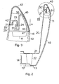
- FIG. 2 shows the insert pot 20 via integrally formed on the bottom 21 spacers 22 on the inside of the bottom 12 of the planter 10.
- the in Fig. 2 area marked by circle III is in Fig. 3 magnified reproduced.
- a unit of support frame 30 and cover support frame 40 has a limited vertical adjustment.
- the support frame 30 is pushed from below onto the insertion pot 20, while the Abdeckhalteahmen 40 is connected from above with the support frame 30, preferably locked.
- the insert pot 20 has an inner shoulder 25 which merges via a vertical leg 21 and a horizontal leg 23 in a downwardly directed web 24.
- the web 24 is inserted into an upwardly open groove 31 of the support frame 30.
- the support frame 30 is connected to the outer leg 32 with the outer leg 42 of the Abdeckhalteahmens 40, preferably latched, as the locking elements 41 show.
- the inner leg 43 of the Abdeckhalteahmens 40th is supported on the inner shoulder 25 of the insert pot 20.
- This lower position of the components adjusts automatically when the insert pot 20 is turned off in the planter 10. From the Fig. 3 is also apparent that the Ein rehabilitation ein the insert pot 20 is canceled in the support frame 30. As indicated by the arrow a, the position is after Fig. 3 caused by the weight of the unit of support frame 30 and cover frame 40 and turns itself after reaching the setting of the insert pot 20 in the planter 10 automatically.
- the planter 10 may have a greater wall thickness than the insert 20, the support frame 30 and the cover 40th
Landscapes
- Life Sciences & Earth Sciences (AREA)
- Environmental Sciences (AREA)
- Engineering & Computer Science (AREA)
- Water Supply & Treatment (AREA)
- Cultivation Receptacles Or Flower-Pots, Or Pots For Seedlings (AREA)
Description
- Die Erfindung betrifft eine Pflanz-Anordnung mit einem Übertopf und einem in den Übertopf einsetzbaren und herausnehmbaren Einsatztopf nach dem Oberbegriff des Anspruches 1.
- Aus der
US 7 886 484 B1 ist eine Pflanztopf-Anordnung bekannt, bei der der Pflanztopf im oberen Außenbereich einen angeformten umlaufenden Steg aufweist, auf dem ein rahmenartiges Teil auflegbar ist. Dieses Teil überragt den Pflanztopf und bildet Auflageflächen für ein ringförmiges Abschlussteil, das sich auf der ringförmigen Oberkante des Pflanztopfes und einem Außensteg des rahmenartigen Teils abstützt. Damit ist an der Oberseite des Pflanztopfes ein geschlossener abgerundeter Abschluss erreicht, der eine robuste Konstruktion darstellt. Das Einsetzen und Herausnehmen eines Einsatztopfes in den Pflanztopf ist bei dieser bekannten Pflanztopf-Anordnung nicht vorgesehen. - Die
US 2010/077660 A1 zeigt einen Pflanztopf, der an der Oberseite mit einem umlaufenden, abstehenden Rand versehen ist, auf dem sich der Rand eines topfartigen Einsatzes mit anderem Rand abstützt. Dieser Einsatz hat eine geringe Höhe und ist nach seiner Herausnahme aus dem Pflanztopf als Untersetzer für den Pflanztopf zu verwenden. Zudem kann der Einsatz verschieden groß ausgelegt und selbst als Pflanztopf verwendet werden. - Schließlich zeigt die
DE 195 15 700 A1 eine Einrichtung zur Aufnahme von Pflanzenerde, die eine rechteckige Aufnahme aus Holz aufweist. Die Seitenwände dieser Holzkiste können auf der Innenseite oder Außenseite längsgerichtete Außenstege aufweisen, auf denen sich ein Plastikeinsatz mit Außenstegen oder Innenstegen abstützt. Der aus Kunststoff bestehende Pflanzeinsatz kann sich auch auf den Oberseiten der Holzkiste abstützen. Anstelle der Auflagestege können die Seitenwände der Holzkiste auch eingearbeitete Auflageaufnahmen aufweisen. Der Einsatz hat in der Regel eine Höhe, die kleiner ist als die Höhe der Holzkiste. Bei dieser Einrichtung ist die Gefahr einer Beschädigung des Kunststoffeinsatzes und damit einer nachfolgenden Verrottung des Holzes sowie das Auftreten von Staunässe vermieden. Vorrichtungen zur leichten Handhabung des Kunststoffeinsatzes beim Herausnehmen aus der Holzkiste sind auch bei dieser bekannten Einrichtung nicht vorhanden. - Eine Pflanztopf-Anordnung mit Pflanztopf und Einsatztopf der eingangs erwähnten Art ist aus der
EP 1 790 212 B1 bekannt. Bei dieser bekannten Pflanztopf-Anordnung ist der Einsatztopf im Bereich des oberen Behälterrandes mit diagonal angeordneten Griffen versehen, die in Griff-Führungen geführt und in eine mit dem Übertopf bündige Einführstellung und in eine am Übertopf vorstehende Ausziehstellung einstellbar sind. Die Griffe können in der Ausziehstellung gefasst und der Einsatztopf aus dem Übertopf herausgenommen werden. Auch das Einsetzen des Einsatztopfes in den Übertopf geschieht mit den in die Ausziehstellung gebrachten Griffen. Danach werden die Griffe in die Einführstellung zurückgestellt, damit die Pflanztopf-Anordnung ohne die abstehenden Griffe einen optisch und gestalterisch guten Eindruck vermitteln. - Dies setzt eine komplizierte konstruktive Ausgestaltung des Einsatztopfes und zusätzliche Handgriffe beim Einsetzen und Herausnehmen des Einsatztopfes voraus.
- Es ist Aufgabe der Erfindung, eine Pflanztopf-Anordnung zu entwickeln, die ohne verstellbare Griffe das Einsetzen und Herausnehmen des Einsatztopfes ermöglicht und dabei nach dem Einsetzen des Einsatztopfes in den Übertopf zusätzliche Handgriffe vermeidet, wobei sich nach dem Einsetzen des Einsatztopfes in den Übertopf automatisch eine optisch ansprechende Konstruktion ergibt.
- Die gestellte Aufgabe wird durch die Merkmale des Anspruches 1 gelöst.
- Dabei weist der Übertopf im Bereich der Oberseite Griffausnehmungen auf, die diagonal angeordnet sind. Der Einsatztopf ist in einen Tragrahmen eingehängt. Der Einsatztopf steht nach dem Einbringen in den Übertopf auf dem Boden des Übertopfes auf, wobei die Einhängestellung des Einsatztopfes durch Absenken des Tragrahmens in eine untere Stellung aufhebbar und der Tragrahmen auf der Oberseite des Übertopfes ablegbar ist. Der Tragrahmen ist über die Griffausnehmungen des Übertopfes fassbar. Nach dem Bringen des Tragrahmens in die Einhängestellung ist der Einsatztopf aus dem Übertopf herausnehmbar.
- Mit dem Tragrahmen kann der Einsatztopf bequem in den Übertopf eingesetzt werden. Beim Erreichen der Einsatzstellung des Einsatztopfes kann der Tragrahmen die Einhängestellung verlassen. Er kann abgesenkt und auf die Oberseite des Übertopfes abgelegt werden. Dabei kann der Tragrahmen an beliebigen Stellen gehalten werden, ohne dass die Hände zwischen dem Tragrahmen und der Oberseite des Übertopfes eingeklemmt werden. Nach dem Freigeben des Tragrahmens durch die Hände fällt der Tragrahmen aufgrund seines Eigengewichtes auf die Oberseite des
- Übertopfes und stellt dadurch automatisch den optischen Eindruck der Pflanztopf-Anordnung her.
- Weitere vorteilhafte Ausgestaltungen der Pflanztopf-Anordnung sind den Unteransprüchen zu entnehmen.
- Damit der Tragrahmen im Bereich der Oberseite des Einsatztopfes festgelegt werden kann, sieht eine Weiterbildung vor, dass der Tragrahmen durch einen Abdeckhalterahmen, der von der Oberseite des Einsatztopfes mit dem Tragrahmen verbindbar ist, im Bereich der Oberseite des Einsatztopfes begrenzt vertikal verstellbar ist.
- Auf diese Weise ist die Einheit aus Tragrahmen und Abdeckhalterahmen am Einsatztopf festgelegt, was die Bedienung der Pflanztopf-Anordnung erleichtert.
- Die vertikale Verstellbewegung des Tragrahmens mit dem Abdeckhalterahmen ist dabei auf mindestens die Abmessung einer zwischen dieser Einheit und der Oberseite des Übertopfes eingeführten Hand begrenzt.
- Der Übertopf, der Einsatztopf, der Tragrahmen und der Abdeckhalterahmen weisen runden, quadratischen, rechteckförmigen oder ovalen Querschnitt auf, wobei die einzelnen Querschnitte aufeinander abgestimmt sind.
- Der Einsatztopf weist am Boden angeformte Abstandshalter auf, die auf der Innenseite des Bodens des Übertopfes aufstehen und die Einstellposition des Einsatztopfes im Übertopf festlegen.
- Der Tragrahmen weist eine nach oben offene Nut auf, in die ein nach unten weisender Steg des Einsatztopfes ragt und dass durch Anschlag des Steges in der Nut die Einhängestellung des Einsatztopfes im Tragrahmen mit dem Abdeckhalterahmen festgelegt ist.
- In der Einhängestellung ist der Tragrahmen mit dem Abdeckhalterahmen in der oberen Stellung des Tragrahmens mit dem Abdeckhalterahmen im Bezug zur Oberseite des Einsatztopfes festgelegt.
- Der Tragrahmen mit dem Abdeckhalterahmen ist bei auf dem Boden des Übertopfes aufgestelltem Einsatztopf in die untere Stellung im Bezug auf den Einsatztopf absenkbar, wobei der Tragrahmen und/oder der Abdeckhalterahmen sich auf der oberen Stirnseite des Übertopfes oder auf einem Innenabsatz des Einsatztopfes abstützt.
- Der Abdeckhalterahmen, der die Oberseite der Pflanztopf-Anordnung abdeckt und den Halt der Einheit aus Tragrahmen und Abdeckhalterahmen am Einsatztopf festlegt, ist auf den Tragrahmen aufgerastet.
- Die Erfindung wird anhand eines in den Zeichnungen dargestellten Ausführungsbeispiels näher erläutert. Es zeigen:
- Fig. 1
- die Seitenansicht der Pflanztopf-Anordnung, wobei der obere Bereich im Schnitt dargestellt ist,
- Fig. 2
- einen Teilschnitt entlang der Linie II-II der
Fig. 1 , - Fig. 3
- den in
Fig. 2 mit dem Kreis III gekennzeichneten Bereich der Pflanztopf-Anordnung in der eingesetzten Stellung des Einsatztopfes und - Fig. 4
- die der
Fig. 3 entsprechenden Bauteile in der Einhängestellung des Einsatztopfes und der Hand beim Erreichen der Einstellstellung des Einsatztopfes im Übertopf. - Aus
Fig. 1 ist eine Pflanztopf-Anordnung mit rundem Querschnitt des Übertopfes 10, des Einsatztopfes 20, des Tragrahmens 30 und des Abdeckhalterahmens 40 zu sehen. Dabei ist im Bereich der Oberseite die Ansicht im Teilschnitt dargestellt, um die einzelnen Bauteile kennzeichnen zu können. Der Boden 12 des Übertopfes 10 trägt außen angeformte Stellplättchen 13. Mit dem Bezugszeichen 11 ist eine der diametral angeordneten Griffausnehmungen bezeichnet, die in der Oberseite des Übertopfes 10 nach oben offen sind. - Ein Füllstandsanzeiger 60 ragt an der Oberseite der Pflanztopf-Anordnung heraus, der in einer Führung des Einsatztopfes 10 bis in den Bereich zwischen dem Boden 12 des Übertopfes 10 und dem Boden 21 des Einsatztopfes 20 ragt und den Flüssigkeitsstand anzeigt.
- Wie
Fig. 2 zeigt, steht der Einsatztopf 20 über am Boden 21 angeformte Abstandshalter 22 auf der Innenseite des Bodens 12 des Übertopfes 10 auf. Der inFig. 2 durch den Kreis III gekennzeichnete Bereich ist inFig. 3 vergrößert wiedergegeben. Dabei ist im Bereich der Oberseite des Einsatztopfes 10 eine Einheit aus Tragrahmen 30 und Abdeckhalterahmen 40 begrenzt vertikal verstellbar festgelegt. Der Tragrahmen 30 ist von unten auf den Einsatztopf 20 aufgeschoben, während der Abdeckhalterahmen 40 von oben her mit dem Tragrahmen 30 verbunden, vorzugsweise verrastet ist. Der Einsatztopf 20 weist einen Innenabsatz 25 auf, der über einen vertikalen Schenkel 21 und einen horizontalen Schenkel 23 in einen nach unten gerichteten Steg 24 übergeht. Der Steg 24 ist in eine nach oben offene Nut 31 des Tragrahmens 30 eingeführt. Der Tragrahmen 30 ist mit dem Außenschenkel 32 mit dem Außenschenkel 42 des Abdeckhalterahmens 40 verbunden, vorzugsweise verrastet, wie die Rastelemente 41 zeigen. Der Innenschenkel 43 des Abdeckhalterahmens 40 stützt sich auf dem Innenabsatz 25 des Einsatztopfes 20 ab. Diese untere Stellung der Bauteile stellt sich automatisch ein, wenn der Einsatztopf 20 im Übertopf 10 abgestellt ist. Aus derFig. 3 ist auch ersichtlich, dass die Einhängestellung des Einsatztopfes 20 im Tragrahmen 30 aufgehoben ist. Wie der Pfeil a andeutet, ist die Stellung nachFig. 3 durch das Eigengewicht der Einheit aus Tragrahmen 30 und Abdeckhalterahmen 40 bedingt und stellt sich nach dem Erreichen der Einstellung des Einsatztopfes 20 im Übertopf 10 automatisch ein. - Anhand der
Fig. 4 lässt sich zeigen, dass die Einhängestellung des Einsatztopfes 20 in der Einheit aus Tragrahmen 30 und Abdeckhalterahmen 40 in der oberen Verstellung der Einheit im Bezug zum Einsatztopf 20 gegeben ist. Die entsprechende Stellung von Einsatztopf 20 und Übertopf 10 ist dabei vorgegeben. Dies bedeutet, dass die Einheit aus Einsatztopf 20 und Übertopf 10 das Fassen der Einheit an beliebiger Stelle zulässt, ohne die Hand 50 zwischen dem Außenschenkel 41 des Abdeckhalterahmens 40 und der Oberseite 15 des Übertopfes 10 einzuklemmen. Die in Richtung des Pfeils 6 verstellte Einheit aus Tragrahmen 30 und Abdeckhalterahmen 40 lässt dabei ausreichenden Platz für die die Einheit fassende hand 50. Gibt die Hand 50 die Einheit aus Tragrahme 30 und Abdeckhalterahmen 40 frei, dann senkt sich die Einheit nach unten ab, wie der Pfeil c andeutet, bis sie schließlich die inFig. 3 gezeigte untere Stellung einnimmt. Dies erfolgt durch das Eigengewicht der Einheit automatisch. - In der Stellung nach
Fig. 3 bleiben die nach oben offenen Griffausnehmungen 11 zum Einführen der Hände frei. Die Einheit wird angehoben und nimmt die Einhängestellung nachFig. 4 ein. Mit der Einheit aus Tragrahmen 30 und Abdeckhalterahmen 40 kann der Einsatztopf 20 nach Einstellung in die Einhängestellung aus dem Übertopf 10 herausgenommen werden. - Der Übertopf 10 kann eine größere Wandstärke aufweisen als der Einsatz 20, der Tragrahmen 30 und der Abdeckrahmen 40.
Claims (10)
- Pflanztopf-Anordnung mit einem Übertopf (10) und einem in den Übertopf (10) einsetzbaren und aus dem Übertopf (10) herausnehmbaren Einsatztopf (20) zur Aufnahme einer Pflanze mit Pflanzenerde, wobei der Übertopf (10) und der Einsatztopf (20) an der Oberseite offen ausgebildet sind,
wobei der Übertopf (10) im Bereich der Oberseite Griffausnehmungen (11) aufweist, dadurch gekennzeichnet,
dass der Einsatztopf (20) in einen Tragrahmen (30) einhängbar ist,
dass der Einsatztopf (20) nach dem Einsetzen in den Übertopf (10) auf dem Boden (12) des Übertopfes (10) aufsteht, wobei die Einhängestellung des Einsatztopfes (10) durch Absenken des Tragrahmens (30) in eine untere Stellung am Einsatztopf (20) aufhebbar und der Tragrahmen (30) auf der Oberseite des Übertopfes (10) ablegbar ist, und
dass der Tragrahmen (30) über die Griffausnehmungen (11) des Übertopfes (10) fassbar und der Einsatztopf (20) nach dem Bringen des Tragrahmens (30) in die Einhängestellung aus dem Übertopf (10) herausnehmbar ist. - Pflanztopf-Anordnung nach Anspruch 1,
dadurch gekennzeichnet,
dass der Tragrahmen (30) durch einen Abdeckhalterahmen (40), der von der Oberseite des Einsatztopfes (20) mit dem Tragrahmen (30) verbindbar ist, im Bereich der Oberseite des Einsatztopfes (20) begrenzt vertikal verstellbar ist. - Pflanztopf-Anordnung nach Anspruch 2,
dadurch gekennzeichnet,
dass die vertikale Verstellbewegung des Tragrahmens (30) mit dem Abdeckhalterahmen (40) auf mindestens die Abmessung einer zwischen dieser Einheit und der Oberseite des Übertopfes (10) eingeführten Hand (50) begrenzt ist. - Pflanztopf-Anordnung nach einem der Ansprüche 1 bis 3,
dadurch gekennzeichnet,
dass der Übertopf (10), der Einsatztopf (20), der Tragrahmen (30) und der Abdeckhalterahmen (40) runden, quadratischen, rechteckförmigen oder ovalen Querschnitt aufweisen, wobei die einzelnen Querschnitte aufeinander abgestimmt sind. - Pflanztopf-Anordnung nach einem der Ansprüche 1 bis 4,
dadurch gekennzeichnet,
dass der Einsatztopf (20) am Außenboden (21) angeformte Abstandshalter (22) aufweist, die auf der Innenseite des Bodens (12) des Übertopfes (10) aufstehen und die Einstellposition des Einsatztopfes (10) im Übertopf (10) festlegen. - Pflanztopf-Anordnung nach einem der Ansprüche 1 bis 5,
dadurch gekennzeichnet,
dass der Tragrahmen (30) eine nach oben offene Nut (31) aufweist, in die ein nach unten weisender Steg (24) des Einsatztopfes (20) ragt und
dass durch Anschlag des Steges (24) in der Nut die obere Einhängestellung des Einsatztopfes (20) im Tragrahmen (30) mit dem Abdeckhalterahmen (40) festgelegt ist. - Pflanztopf-Anordnung nach Anspruch 6,
dadurch gekennzeichnet,
dass in der Einhängestellung der Tragrahmen (30) mit dem Abdeckrahmen (40) in der oberen Stellung des Tragrahmens (30) mit dem Abdeckhalterahmen (40) im Bezug zur Oberseite des Einsatztopfes (10) festgelegt ist. - Pflanztopf-Anordnung nach einem der Ansprüche 1 bis 7,
dadurch gekennzeichnet,
das der Tragrahmen (30) mit dem Abdeckhalterahmen (40) bei auf dem Boden (12) des Übertopfes (10) aufgestelltem Einsatztopfes (20) in die untere Stellung im Bezug auf den Einsatztopf (20) absenkbar ist, wobei der Tragrahmen (30) und/oder der Abdeckhalterahmen (40) sich auf der oberen Stirnseite des Übertopfes (10) oder auf einem Innenabsatz (45) des Einsatztopfes (20) abstützt. - Pflanztopf-Anordnung nach einem der Ansprüche 1 bis 8,
dadurch gekennzeichnet,
dass der Übertopf (10), der Einsatztopf (20), der Tragrahmen (30) und der Abdeckhalterahmen (40) aus Kunststoff bestehen, wobei der Übertopf (10) größere Wandstärke aufweist. - Pflanztopf-Anordnung nach einem der Ansprüche 2 bis 9,
dadurch gekennzeichnet,
dass der Abdeckhalterahmen (40) auf den Tragrahmen (30) aufgerastet ist.
Priority Applications (2)
| Application Number | Priority Date | Filing Date | Title |
|---|---|---|---|
| PL12766879T PL2753167T3 (pl) | 2011-09-05 | 2012-09-04 | Układ doniczki z osłonką i wkładem doniczkowym wkładanym do osłonki i z niej wyjmowanym |
| EP12766879.6A EP2753167B1 (de) | 2011-09-05 | 2012-09-04 | Pflanztopf-anordnung mit einem übertopf und einem in den übertopf einsetzbaren und herausnehmbaren einsatztopf |
Applications Claiming Priority (3)
| Application Number | Priority Date | Filing Date | Title |
|---|---|---|---|
| EP11180023A EP2564690A1 (de) | 2011-09-05 | 2011-09-05 | Pflanztopf-Anordnung mit einem Übertopf und einem in den Übertopf einsetzbaren und herausnehmbaren Einsatztopf |
| EP12766879.6A EP2753167B1 (de) | 2011-09-05 | 2012-09-04 | Pflanztopf-anordnung mit einem übertopf und einem in den übertopf einsetzbaren und herausnehmbaren einsatztopf |
| PCT/EP2012/003685 WO2013034274A1 (de) | 2011-09-05 | 2012-09-04 | Pflanztopf-anordnung mit einem übertopf und einem in den übertopf einsetzbaren und herausnehmbaren einsatztopf |
Publications (2)
| Publication Number | Publication Date |
|---|---|
| EP2753167A1 EP2753167A1 (de) | 2014-07-16 |
| EP2753167B1 true EP2753167B1 (de) | 2015-11-18 |
Family
ID=46968124
Family Applications (2)
| Application Number | Title | Priority Date | Filing Date |
|---|---|---|---|
| EP11180023A Withdrawn EP2564690A1 (de) | 2011-09-05 | 2011-09-05 | Pflanztopf-Anordnung mit einem Übertopf und einem in den Übertopf einsetzbaren und herausnehmbaren Einsatztopf |
| EP12766879.6A Not-in-force EP2753167B1 (de) | 2011-09-05 | 2012-09-04 | Pflanztopf-anordnung mit einem übertopf und einem in den übertopf einsetzbaren und herausnehmbaren einsatztopf |
Family Applications Before (1)
| Application Number | Title | Priority Date | Filing Date |
|---|---|---|---|
| EP11180023A Withdrawn EP2564690A1 (de) | 2011-09-05 | 2011-09-05 | Pflanztopf-Anordnung mit einem Übertopf und einem in den Übertopf einsetzbaren und herausnehmbaren Einsatztopf |
Country Status (6)
| Country | Link |
|---|---|
| US (1) | US20140325905A1 (de) |
| EP (2) | EP2564690A1 (de) |
| CN (1) | CN103841819B (de) |
| EA (1) | EA201400283A1 (de) |
| PL (1) | PL2753167T3 (de) |
| WO (1) | WO2013034274A1 (de) |
Cited By (1)
| Publication number | Priority date | Publication date | Assignee | Title |
|---|---|---|---|---|
| EP3730004A1 (de) | 2019-04-23 | 2020-10-28 | Saly, Lucia | Pflanztopfhalter |
Families Citing this family (2)
| Publication number | Priority date | Publication date | Assignee | Title |
|---|---|---|---|---|
| CN203951945U (zh) * | 2014-06-16 | 2014-11-26 | 何超群 | 新型植物种植辅助装置 |
| US12171174B1 (en) | 2023-06-14 | 2024-12-24 | Lawrence Metrick | Planter assembly |
Family Cites Families (35)
| Publication number | Priority date | Publication date | Assignee | Title |
|---|---|---|---|---|
| US151142A (en) * | 1874-05-19 | Xjixikft a ajijivh | ||
| US1077660A (en) | 1913-08-07 | 1913-11-04 | Curtain Supply Co | Vestibule-curtain mounting. |
| US3331524A (en) * | 1964-07-06 | 1967-07-18 | Rudkin Wiley Corp | Window box for potted plants |
| US3534498A (en) * | 1968-04-16 | 1970-10-20 | Peter Herrli | Installation for plants |
| CA1007182A (en) * | 1973-02-07 | 1977-03-22 | Robert H. Day | Cups for holding ingredients for drinks |
| US3804331A (en) * | 1973-04-23 | 1974-04-16 | Days Ease Home Prod Corp | Decorative room air treating device |
| US4236352A (en) * | 1978-10-18 | 1980-12-02 | Heaney William B | Plant watering device |
| DE2934494A1 (de) * | 1979-08-25 | 1981-03-26 | Hölter, Heinz, Prof. Dr.sc., Dr.-Ing., 45964 Gladbeck | Innenblumentopf mit membranbewaesserung und klemmvorrichtung gegen aufschwimmen |
| DE3240269C1 (de) * | 1982-10-30 | 1984-05-30 | Zeischegg, Walter, 7900 Ulm | Pflanzengefaess,insbesondere fuer Hydrokultur |
| DE3740100A1 (de) * | 1987-11-26 | 1989-06-08 | Wolfram Elwert | Blumentopf mit uebertopf |
| CN2059294U (zh) * | 1989-07-25 | 1990-07-18 | 刘玉堂 | 外光里粗双层陶质花盆 |
| US5282335A (en) * | 1992-03-03 | 1994-02-01 | Holtkamp Reinhold Jr | Self-watering dish garden for plants |
| CN2220723Y (zh) * | 1993-07-25 | 1996-02-28 | 孙景振 | 反注水式双层花盆 |
| DE9409269U1 (de) * | 1994-06-08 | 1994-09-29 | Pfeiffer, Harald, 52379 Langerwehe | Einrichtung für die Aufnahme eines Kunststoffeinsatzes zur Aufnahme von Pflanzenerde |
| US6006472A (en) * | 1994-12-01 | 1999-12-28 | International Plant Breeding Ag. | Fragrance emitting plant watering system |
| US5782035A (en) * | 1995-06-07 | 1998-07-21 | Locke; Randal D. | Multi-purpose automatic filling and leveling fluid basin with water transfer |
| CN2222998Y (zh) * | 1995-08-28 | 1996-03-27 | 于云文 | 多用种养花卉盆 |
| JPH09191770A (ja) * | 1996-01-22 | 1997-07-29 | Horon Corp:Kk | 二重植木鉢 |
| CA2186920C (en) * | 1996-02-08 | 1999-09-28 | Hong Ku Park | Plant sprouting pot |
| NL1004215C2 (nl) * | 1996-10-07 | 1998-04-10 | Avot Beheer Bv | Afschermhouder voor een pot- of bakvormige houder. |
| CN2304241Y (zh) * | 1997-10-22 | 1999-01-20 | 孙广 | 一种双层可调屏壁式组合花盆 |
| JPH11253054A (ja) * | 1998-03-12 | 1999-09-21 | Minoru Ind Co Ltd | 植物栽培用二重鉢 |
| CN2411666Y (zh) * | 2000-01-26 | 2000-12-27 | 唐文均 | 全能型双层花盆 |
| JP2002119142A (ja) * | 2000-08-08 | 2002-04-23 | Kaisui Maren:Kk | 飾り鉢 |
| US6823624B2 (en) * | 2001-07-17 | 2004-11-30 | S.I.T., Inc. | Plastic article with protuberance |
| CN2562562Y (zh) * | 2002-09-02 | 2003-07-30 | 王瑞卓 | 双壁花盆 |
| US7171781B1 (en) * | 2003-01-29 | 2007-02-06 | Amerikan, Llc | Plant pot coding |
| US7131289B2 (en) * | 2004-06-29 | 2006-11-07 | The Glad Products Company | Container |
| DE202005018519U1 (de) | 2005-11-26 | 2007-04-05 | Geobra Brandstätter GmbH & Co. KG | Pflanztopf-Anordnung |
| US8348084B2 (en) * | 2006-08-14 | 2013-01-08 | Edison Nation, Llc | Container having surrounding handle and gimbal |
| US7874102B2 (en) * | 2006-09-28 | 2011-01-25 | Stuart Hilbert | Decorative surround for plants |
| US7730666B2 (en) * | 2006-11-09 | 2010-06-08 | David Allen Spray | Plant container with watering system |
| US20100077660A1 (en) * | 2008-09-26 | 2010-04-01 | Laura Messano | Suspended planting platform for a plant container |
| JP2010154827A (ja) * | 2008-12-29 | 2010-07-15 | Uchida Tatsusaburo | 植物栽培容器 |
| US7886484B1 (en) * | 2010-03-19 | 2011-02-15 | Robert Chen | Plant pot |
-
2011
- 2011-09-05 EP EP11180023A patent/EP2564690A1/de not_active Withdrawn
-
2012
- 2012-09-04 US US14/342,540 patent/US20140325905A1/en not_active Abandoned
- 2012-09-04 PL PL12766879T patent/PL2753167T3/pl unknown
- 2012-09-04 EP EP12766879.6A patent/EP2753167B1/de not_active Not-in-force
- 2012-09-04 EA EA201400283A patent/EA201400283A1/ru unknown
- 2012-09-04 WO PCT/EP2012/003685 patent/WO2013034274A1/de not_active Ceased
- 2012-09-04 CN CN201280049013.7A patent/CN103841819B/zh not_active Expired - Fee Related
Cited By (1)
| Publication number | Priority date | Publication date | Assignee | Title |
|---|---|---|---|---|
| EP3730004A1 (de) | 2019-04-23 | 2020-10-28 | Saly, Lucia | Pflanztopfhalter |
Also Published As
| Publication number | Publication date |
|---|---|
| PL2753167T3 (pl) | 2016-06-30 |
| EP2564690A1 (de) | 2013-03-06 |
| WO2013034274A8 (de) | 2013-06-20 |
| EA201400283A1 (ru) | 2014-06-30 |
| CN103841819A (zh) | 2014-06-04 |
| US20140325905A1 (en) | 2014-11-06 |
| WO2013034274A1 (de) | 2013-03-14 |
| CN103841819B (zh) | 2017-02-15 |
| EP2753167A1 (de) | 2014-07-16 |
Similar Documents
| Publication | Publication Date | Title |
|---|---|---|
| EP2340743B9 (de) | Schublade für einen Küchenschrank | |
| EP1716779B1 (de) | Bodenlose Schublade und Aufnahmerahmen dafür | |
| DE2710679B2 (de) | Aufzuchttopf für Pflanzen | |
| WO2013034274A1 (de) | Pflanztopf-anordnung mit einem übertopf und einem in den übertopf einsetzbaren und herausnehmbaren einsatztopf | |
| DE2620977A1 (de) | Komposter fuer hausmuell und gartenabfaelle | |
| DE202013007621U1 (de) | Verbesserte höhenanpassbare Hauseinführung für eine Gebäudebodenplatte | |
| DE102018132346A1 (de) | Pflanztopf mit Bewässerungssystem | |
| DE29712649U1 (de) | Pflanzenständer | |
| DE102022128357A1 (de) | Pflanzmodul für einen hängenden Garten | |
| DE202022106034U1 (de) | Pflanzmodul für einen hängenden Garten | |
| DE3906121C2 (de) | Pflanzenkübel für Dekorationszwecke an einem Pfahl oder Pfosten | |
| AT411421B (de) | Höhenverstellbare duschwanne | |
| DE3742558A1 (de) | Pflanzenkasten oder dergleichen fuer einen doppelboden | |
| AT13102U1 (de) | Hochbeet | |
| DE1482977A1 (de) | Anzuchttopf aus Kunststoff | |
| EP0310789B1 (de) | Durchbrochener Pflanzenbehälter für Epiphyten | |
| CH715341B1 (de) | Variables Pflanzbehältersystem, insbesondere variables Hochbeet-System. | |
| DE202012102743U1 (de) | Pflanzbehältnis-Anordnung | |
| EP3682727A1 (de) | Pflanzenpalette | |
| DE202010010429U1 (de) | Vorrichtung zur Verlängerung eines Möbelfußes eines Möbelstücks | |
| DE8507436U1 (de) | Organisations-Schubkasten | |
| DE8707860U1 (de) | Tragelement für Blumentöpfe, Becher od.dgl. | |
| EP2335474A1 (de) | Pflanzwanne | |
| DE102008037187B4 (de) | Pflanztopf | |
| DE202012103355U1 (de) | Einsatz für eine Pflanzbehältnis-Anordnung |
Legal Events
| Date | Code | Title | Description |
|---|---|---|---|
| PUAI | Public reference made under article 153(3) epc to a published international application that has entered the european phase |
Free format text: ORIGINAL CODE: 0009012 |
|
| 17P | Request for examination filed |
Effective date: 20140407 |
|
| AK | Designated contracting states |
Kind code of ref document: A1 Designated state(s): AL AT BE BG CH CY CZ DE DK EE ES FI FR GB GR HR HU IE IS IT LI LT LU LV MC MK MT NL NO PL PT RO RS SE SI SK SM TR |
|
| DAX | Request for extension of the european patent (deleted) | ||
| GRAP | Despatch of communication of intention to grant a patent |
Free format text: ORIGINAL CODE: EPIDOSNIGR1 |
|
| INTG | Intention to grant announced |
Effective date: 20150401 |
|
| GRAS | Grant fee paid |
Free format text: ORIGINAL CODE: EPIDOSNIGR3 |
|
| GRAA | (expected) grant |
Free format text: ORIGINAL CODE: 0009210 |
|
| AK | Designated contracting states |
Kind code of ref document: B1 Designated state(s): AL AT BE BG CH CY CZ DE DK EE ES FI FR GB GR HR HU IE IS IT LI LT LU LV MC MK MT NL NO PL PT RO RS SE SI SK SM TR |
|
| REG | Reference to a national code |
Ref country code: GB Ref legal event code: FG4D Free format text: NOT ENGLISH |
|
| REG | Reference to a national code |
Ref country code: CH Ref legal event code: EP |
|
| REG | Reference to a national code |
Ref country code: AT Ref legal event code: REF Ref document number: 761035 Country of ref document: AT Kind code of ref document: T Effective date: 20151215 |
|
| REG | Reference to a national code |
Ref country code: IE Ref legal event code: FG4D Free format text: LANGUAGE OF EP DOCUMENT: GERMAN |
|
| REG | Reference to a national code |
Ref country code: DE Ref legal event code: R096 Ref document number: 502012005274 Country of ref document: DE |
|
| REG | Reference to a national code |
Ref country code: NL Ref legal event code: MP Effective date: 20160218 |
|
| REG | Reference to a national code |
Ref country code: LT Ref legal event code: MG4D |
|
| PG25 | Lapsed in a contracting state [announced via postgrant information from national office to epo] |
Ref country code: IS Free format text: LAPSE BECAUSE OF FAILURE TO SUBMIT A TRANSLATION OF THE DESCRIPTION OR TO PAY THE FEE WITHIN THE PRESCRIBED TIME-LIMIT Effective date: 20160318 Ref country code: NO Free format text: LAPSE BECAUSE OF FAILURE TO SUBMIT A TRANSLATION OF THE DESCRIPTION OR TO PAY THE FEE WITHIN THE PRESCRIBED TIME-LIMIT Effective date: 20160218 Ref country code: LT Free format text: LAPSE BECAUSE OF FAILURE TO SUBMIT A TRANSLATION OF THE DESCRIPTION OR TO PAY THE FEE WITHIN THE PRESCRIBED TIME-LIMIT Effective date: 20151118 Ref country code: NL Free format text: LAPSE BECAUSE OF FAILURE TO SUBMIT A TRANSLATION OF THE DESCRIPTION OR TO PAY THE FEE WITHIN THE PRESCRIBED TIME-LIMIT Effective date: 20151118 Ref country code: ES Free format text: LAPSE BECAUSE OF FAILURE TO SUBMIT A TRANSLATION OF THE DESCRIPTION OR TO PAY THE FEE WITHIN THE PRESCRIBED TIME-LIMIT Effective date: 20151118 Ref country code: HR Free format text: LAPSE BECAUSE OF FAILURE TO SUBMIT A TRANSLATION OF THE DESCRIPTION OR TO PAY THE FEE WITHIN THE PRESCRIBED TIME-LIMIT Effective date: 20151118 |
|
| PG25 | Lapsed in a contracting state [announced via postgrant information from national office to epo] |
Ref country code: RS Free format text: LAPSE BECAUSE OF FAILURE TO SUBMIT A TRANSLATION OF THE DESCRIPTION OR TO PAY THE FEE WITHIN THE PRESCRIBED TIME-LIMIT Effective date: 20151118 Ref country code: GR Free format text: LAPSE BECAUSE OF FAILURE TO SUBMIT A TRANSLATION OF THE DESCRIPTION OR TO PAY THE FEE WITHIN THE PRESCRIBED TIME-LIMIT Effective date: 20160219 Ref country code: PT Free format text: LAPSE BECAUSE OF FAILURE TO SUBMIT A TRANSLATION OF THE DESCRIPTION OR TO PAY THE FEE WITHIN THE PRESCRIBED TIME-LIMIT Effective date: 20160318 Ref country code: FI Free format text: LAPSE BECAUSE OF FAILURE TO SUBMIT A TRANSLATION OF THE DESCRIPTION OR TO PAY THE FEE WITHIN THE PRESCRIBED TIME-LIMIT Effective date: 20151118 Ref country code: LV Free format text: LAPSE BECAUSE OF FAILURE TO SUBMIT A TRANSLATION OF THE DESCRIPTION OR TO PAY THE FEE WITHIN THE PRESCRIBED TIME-LIMIT Effective date: 20151118 Ref country code: SE Free format text: LAPSE BECAUSE OF FAILURE TO SUBMIT A TRANSLATION OF THE DESCRIPTION OR TO PAY THE FEE WITHIN THE PRESCRIBED TIME-LIMIT Effective date: 20151118 |
|
| REG | Reference to a national code |
Ref country code: DE Ref legal event code: R097 Ref document number: 502012005274 Country of ref document: DE |
|
| PG25 | Lapsed in a contracting state [announced via postgrant information from national office to epo] |
Ref country code: DK Free format text: LAPSE BECAUSE OF FAILURE TO SUBMIT A TRANSLATION OF THE DESCRIPTION OR TO PAY THE FEE WITHIN THE PRESCRIBED TIME-LIMIT Effective date: 20151118 Ref country code: EE Free format text: LAPSE BECAUSE OF FAILURE TO SUBMIT A TRANSLATION OF THE DESCRIPTION OR TO PAY THE FEE WITHIN THE PRESCRIBED TIME-LIMIT Effective date: 20151118 Ref country code: SM Free format text: LAPSE BECAUSE OF FAILURE TO SUBMIT A TRANSLATION OF THE DESCRIPTION OR TO PAY THE FEE WITHIN THE PRESCRIBED TIME-LIMIT Effective date: 20151118 Ref country code: RO Free format text: LAPSE BECAUSE OF FAILURE TO SUBMIT A TRANSLATION OF THE DESCRIPTION OR TO PAY THE FEE WITHIN THE PRESCRIBED TIME-LIMIT Effective date: 20151118 Ref country code: SK Free format text: LAPSE BECAUSE OF FAILURE TO SUBMIT A TRANSLATION OF THE DESCRIPTION OR TO PAY THE FEE WITHIN THE PRESCRIBED TIME-LIMIT Effective date: 20151118 |
|
| PLBE | No opposition filed within time limit |
Free format text: ORIGINAL CODE: 0009261 |
|
| STAA | Information on the status of an ep patent application or granted ep patent |
Free format text: STATUS: NO OPPOSITION FILED WITHIN TIME LIMIT |
|
| 26N | No opposition filed |
Effective date: 20160819 |
|
| REG | Reference to a national code |
Ref country code: FR Ref legal event code: PLFP Year of fee payment: 5 |
|
| PG25 | Lapsed in a contracting state [announced via postgrant information from national office to epo] |
Ref country code: SI Free format text: LAPSE BECAUSE OF FAILURE TO SUBMIT A TRANSLATION OF THE DESCRIPTION OR TO PAY THE FEE WITHIN THE PRESCRIBED TIME-LIMIT Effective date: 20151118 |
|
| PG25 | Lapsed in a contracting state [announced via postgrant information from national office to epo] |
Ref country code: BE Free format text: LAPSE BECAUSE OF NON-PAYMENT OF DUE FEES Effective date: 20160930 |
|
| PG25 | Lapsed in a contracting state [announced via postgrant information from national office to epo] |
Ref country code: MC Free format text: LAPSE BECAUSE OF FAILURE TO SUBMIT A TRANSLATION OF THE DESCRIPTION OR TO PAY THE FEE WITHIN THE PRESCRIBED TIME-LIMIT Effective date: 20151118 |
|
| REG | Reference to a national code |
Ref country code: IE Ref legal event code: MM4A |
|
| PG25 | Lapsed in a contracting state [announced via postgrant information from national office to epo] |
Ref country code: IE Free format text: LAPSE BECAUSE OF NON-PAYMENT OF DUE FEES Effective date: 20160904 |
|
| PG25 | Lapsed in a contracting state [announced via postgrant information from national office to epo] |
Ref country code: IT Free format text: LAPSE BECAUSE OF NON-PAYMENT OF DUE FEES Effective date: 20160904 Ref country code: LU Free format text: LAPSE BECAUSE OF NON-PAYMENT OF DUE FEES Effective date: 20160904 |
|
| REG | Reference to a national code |
Ref country code: DE Ref legal event code: R082 Ref document number: 502012005274 Country of ref document: DE Representative=s name: JECK - FLECK PATENTANWAELTE, DE |
|
| REG | Reference to a national code |
Ref country code: FR Ref legal event code: PLFP Year of fee payment: 6 |
|
| REG | Reference to a national code |
Ref country code: BE Ref legal event code: MM Effective date: 20160930 |
|
| PG25 | Lapsed in a contracting state [announced via postgrant information from national office to epo] |
Ref country code: CY Free format text: LAPSE BECAUSE OF FAILURE TO SUBMIT A TRANSLATION OF THE DESCRIPTION OR TO PAY THE FEE WITHIN THE PRESCRIBED TIME-LIMIT Effective date: 20151118 Ref country code: HU Free format text: LAPSE BECAUSE OF FAILURE TO SUBMIT A TRANSLATION OF THE DESCRIPTION OR TO PAY THE FEE WITHIN THE PRESCRIBED TIME-LIMIT; INVALID AB INITIO Effective date: 20120904 |
|
| PG25 | Lapsed in a contracting state [announced via postgrant information from national office to epo] |
Ref country code: MK Free format text: LAPSE BECAUSE OF FAILURE TO SUBMIT A TRANSLATION OF THE DESCRIPTION OR TO PAY THE FEE WITHIN THE PRESCRIBED TIME-LIMIT Effective date: 20151118 Ref country code: MT Free format text: LAPSE BECAUSE OF FAILURE TO SUBMIT A TRANSLATION OF THE DESCRIPTION OR TO PAY THE FEE WITHIN THE PRESCRIBED TIME-LIMIT Effective date: 20151118 |
|
| PG25 | Lapsed in a contracting state [announced via postgrant information from national office to epo] |
Ref country code: BG Free format text: LAPSE BECAUSE OF FAILURE TO SUBMIT A TRANSLATION OF THE DESCRIPTION OR TO PAY THE FEE WITHIN THE PRESCRIBED TIME-LIMIT Effective date: 20151118 |
|
| PG25 | Lapsed in a contracting state [announced via postgrant information from national office to epo] |
Ref country code: TR Free format text: LAPSE BECAUSE OF FAILURE TO SUBMIT A TRANSLATION OF THE DESCRIPTION OR TO PAY THE FEE WITHIN THE PRESCRIBED TIME-LIMIT Effective date: 20151118 Ref country code: AL Free format text: LAPSE BECAUSE OF FAILURE TO SUBMIT A TRANSLATION OF THE DESCRIPTION OR TO PAY THE FEE WITHIN THE PRESCRIBED TIME-LIMIT Effective date: 20151118 |
|
| PGFP | Annual fee paid to national office [announced via postgrant information from national office to epo] |
Ref country code: CZ Payment date: 20180912 Year of fee payment: 7 |
|
| PGFP | Annual fee paid to national office [announced via postgrant information from national office to epo] |
Ref country code: PL Payment date: 20181220 Year of fee payment: 7 Ref country code: AT Payment date: 20181220 Year of fee payment: 7 |
|
| PGFP | Annual fee paid to national office [announced via postgrant information from national office to epo] |
Ref country code: FR Payment date: 20181221 Year of fee payment: 8 Ref country code: CH Payment date: 20181218 Year of fee payment: 7 Ref country code: GB Payment date: 20181218 Year of fee payment: 7 |
|
| PGFP | Annual fee paid to national office [announced via postgrant information from national office to epo] |
Ref country code: DE Payment date: 20181228 Year of fee payment: 7 |
|
| REG | Reference to a national code |
Ref country code: DE Ref legal event code: R119 Ref document number: 502012005274 Country of ref document: DE |
|
| PG25 | Lapsed in a contracting state [announced via postgrant information from national office to epo] |
Ref country code: CZ Free format text: LAPSE BECAUSE OF NON-PAYMENT OF DUE FEES Effective date: 20190904 |
|
| REG | Reference to a national code |
Ref country code: CH Ref legal event code: PL |
|
| PG25 | Lapsed in a contracting state [announced via postgrant information from national office to epo] |
Ref country code: DE Free format text: LAPSE BECAUSE OF NON-PAYMENT OF DUE FEES Effective date: 20200401 Ref country code: LI Free format text: LAPSE BECAUSE OF NON-PAYMENT OF DUE FEES Effective date: 20190930 Ref country code: CH Free format text: LAPSE BECAUSE OF NON-PAYMENT OF DUE FEES Effective date: 20190930 |
|
| REG | Reference to a national code |
Ref country code: AT Ref legal event code: MM01 Ref document number: 761035 Country of ref document: AT Kind code of ref document: T Effective date: 20190904 |
|
| GBPC | Gb: european patent ceased through non-payment of renewal fee |
Effective date: 20190904 |
|
| PG25 | Lapsed in a contracting state [announced via postgrant information from national office to epo] |
Ref country code: GB Free format text: LAPSE BECAUSE OF NON-PAYMENT OF DUE FEES Effective date: 20190904 Ref country code: FR Free format text: LAPSE BECAUSE OF NON-PAYMENT OF DUE FEES Effective date: 20190930 |
|
| PG25 | Lapsed in a contracting state [announced via postgrant information from national office to epo] |
Ref country code: AT Free format text: LAPSE BECAUSE OF NON-PAYMENT OF DUE FEES Effective date: 20190904 |
|
| PG25 | Lapsed in a contracting state [announced via postgrant information from national office to epo] |
Ref country code: PL Free format text: LAPSE BECAUSE OF NON-PAYMENT OF DUE FEES Effective date: 20190904 |