EP2755848B1 - Procede de surveillance du filtre capacitif d'un chargeur de batterie - Google Patents
Procede de surveillance du filtre capacitif d'un chargeur de batterie Download PDFInfo
- Publication number
- EP2755848B1 EP2755848B1 EP12767056.0A EP12767056A EP2755848B1 EP 2755848 B1 EP2755848 B1 EP 2755848B1 EP 12767056 A EP12767056 A EP 12767056A EP 2755848 B1 EP2755848 B1 EP 2755848B1
- Authority
- EP
- European Patent Office
- Prior art keywords
- phase
- battery
- power supply
- current
- supply network
- Prior art date
- Legal status (The legal status is an assumption and is not a legal conclusion. Google has not performed a legal analysis and makes no representation as to the accuracy of the status listed.)
- Active
Links
Images


Classifications
-
- B—PERFORMING OPERATIONS; TRANSPORTING
- B60—VEHICLES IN GENERAL
- B60L—PROPULSION OF ELECTRICALLY-PROPELLED VEHICLES; SUPPLYING ELECTRIC POWER FOR AUXILIARY EQUIPMENT OF ELECTRICALLY-PROPELLED VEHICLES; ELECTRODYNAMIC BRAKE SYSTEMS FOR VEHICLES IN GENERAL; MAGNETIC SUSPENSION OR LEVITATION FOR VEHICLES; MONITORING OPERATING VARIABLES OF ELECTRICALLY-PROPELLED VEHICLES; ELECTRIC SAFETY DEVICES FOR ELECTRICALLY-PROPELLED VEHICLES
- B60L50/00—Electric propulsion with power supplied within the vehicle
- B60L50/40—Electric propulsion with power supplied within the vehicle using propulsion power supplied by capacitors
-
- B—PERFORMING OPERATIONS; TRANSPORTING
- B60—VEHICLES IN GENERAL
- B60L—PROPULSION OF ELECTRICALLY-PROPELLED VEHICLES; SUPPLYING ELECTRIC POWER FOR AUXILIARY EQUIPMENT OF ELECTRICALLY-PROPELLED VEHICLES; ELECTRODYNAMIC BRAKE SYSTEMS FOR VEHICLES IN GENERAL; MAGNETIC SUSPENSION OR LEVITATION FOR VEHICLES; MONITORING OPERATING VARIABLES OF ELECTRICALLY-PROPELLED VEHICLES; ELECTRIC SAFETY DEVICES FOR ELECTRICALLY-PROPELLED VEHICLES
- B60L3/00—Electric devices on electrically-propelled vehicles for safety purposes; Monitoring operating variables, e.g. speed, deceleration or energy consumption
- B60L3/0023—Detecting, eliminating, remedying or compensating for drive train abnormalities, e.g. failures within the drive train
- B60L3/003—Detecting, eliminating, remedying or compensating for drive train abnormalities, e.g. failures within the drive train relating to inverters
-
- B—PERFORMING OPERATIONS; TRANSPORTING
- B60—VEHICLES IN GENERAL
- B60L—PROPULSION OF ELECTRICALLY-PROPELLED VEHICLES; SUPPLYING ELECTRIC POWER FOR AUXILIARY EQUIPMENT OF ELECTRICALLY-PROPELLED VEHICLES; ELECTRODYNAMIC BRAKE SYSTEMS FOR VEHICLES IN GENERAL; MAGNETIC SUSPENSION OR LEVITATION FOR VEHICLES; MONITORING OPERATING VARIABLES OF ELECTRICALLY-PROPELLED VEHICLES; ELECTRIC SAFETY DEVICES FOR ELECTRICALLY-PROPELLED VEHICLES
- B60L3/00—Electric devices on electrically-propelled vehicles for safety purposes; Monitoring operating variables, e.g. speed, deceleration or energy consumption
- B60L3/04—Cutting off the power supply under fault conditions
-
- B—PERFORMING OPERATIONS; TRANSPORTING
- B60—VEHICLES IN GENERAL
- B60L—PROPULSION OF ELECTRICALLY-PROPELLED VEHICLES; SUPPLYING ELECTRIC POWER FOR AUXILIARY EQUIPMENT OF ELECTRICALLY-PROPELLED VEHICLES; ELECTRODYNAMIC BRAKE SYSTEMS FOR VEHICLES IN GENERAL; MAGNETIC SUSPENSION OR LEVITATION FOR VEHICLES; MONITORING OPERATING VARIABLES OF ELECTRICALLY-PROPELLED VEHICLES; ELECTRIC SAFETY DEVICES FOR ELECTRICALLY-PROPELLED VEHICLES
- B60L50/00—Electric propulsion with power supplied within the vehicle
- B60L50/50—Electric propulsion with power supplied within the vehicle using propulsion power supplied by batteries or fuel cells
- B60L50/51—Electric propulsion with power supplied within the vehicle using propulsion power supplied by batteries or fuel cells characterised by AC-motors
-
- B—PERFORMING OPERATIONS; TRANSPORTING
- B60—VEHICLES IN GENERAL
- B60L—PROPULSION OF ELECTRICALLY-PROPELLED VEHICLES; SUPPLYING ELECTRIC POWER FOR AUXILIARY EQUIPMENT OF ELECTRICALLY-PROPELLED VEHICLES; ELECTRODYNAMIC BRAKE SYSTEMS FOR VEHICLES IN GENERAL; MAGNETIC SUSPENSION OR LEVITATION FOR VEHICLES; MONITORING OPERATING VARIABLES OF ELECTRICALLY-PROPELLED VEHICLES; ELECTRIC SAFETY DEVICES FOR ELECTRICALLY-PROPELLED VEHICLES
- B60L53/00—Methods of charging batteries, specially adapted for electric vehicles; Charging stations or on-board charging equipment therefor; Exchange of energy storage elements in electric vehicles
- B60L53/20—Methods of charging batteries, specially adapted for electric vehicles; Charging stations or on-board charging equipment therefor; Exchange of energy storage elements in electric vehicles characterised by converters located in the vehicle
- B60L53/22—Constructional details or arrangements of charging converters specially adapted for charging electric vehicles
-
- B—PERFORMING OPERATIONS; TRANSPORTING
- B60—VEHICLES IN GENERAL
- B60L—PROPULSION OF ELECTRICALLY-PROPELLED VEHICLES; SUPPLYING ELECTRIC POWER FOR AUXILIARY EQUIPMENT OF ELECTRICALLY-PROPELLED VEHICLES; ELECTRODYNAMIC BRAKE SYSTEMS FOR VEHICLES IN GENERAL; MAGNETIC SUSPENSION OR LEVITATION FOR VEHICLES; MONITORING OPERATING VARIABLES OF ELECTRICALLY-PROPELLED VEHICLES; ELECTRIC SAFETY DEVICES FOR ELECTRICALLY-PROPELLED VEHICLES
- B60L58/00—Methods or circuit arrangements for monitoring or controlling batteries or fuel cells, specially adapted for electric vehicles
- B60L58/10—Methods or circuit arrangements for monitoring or controlling batteries or fuel cells, specially adapted for electric vehicles for monitoring or controlling batteries
-
- G—PHYSICS
- G01—MEASURING; TESTING
- G01R—MEASURING ELECTRIC VARIABLES; MEASURING MAGNETIC VARIABLES
- G01R31/00—Arrangements for testing electric properties; Arrangements for locating electric faults; Arrangements for electrical testing characterised by what is being tested not provided for elsewhere
- G01R31/36—Arrangements for testing, measuring or monitoring the electrical condition of accumulators or electric batteries, e.g. capacity or state of charge [SoC]
- G01R31/3644—Constructional arrangements
-
- G—PHYSICS
- G01—MEASURING; TESTING
- G01R—MEASURING ELECTRIC VARIABLES; MEASURING MAGNETIC VARIABLES
- G01R31/00—Arrangements for testing electric properties; Arrangements for locating electric faults; Arrangements for electrical testing characterised by what is being tested not provided for elsewhere
- G01R31/50—Testing of electric apparatus, lines, cables or components for short-circuits, continuity, leakage current or incorrect line connections
-
- H—ELECTRICITY
- H01—ELECTRIC ELEMENTS
- H01M—PROCESSES OR MEANS, e.g. BATTERIES, FOR THE DIRECT CONVERSION OF CHEMICAL ENERGY INTO ELECTRICAL ENERGY
- H01M10/00—Secondary cells; Manufacture thereof
- H01M10/42—Methods or arrangements for servicing or maintenance of secondary cells or secondary half-cells
- H01M10/44—Methods for charging or discharging
-
- H—ELECTRICITY
- H01—ELECTRIC ELEMENTS
- H01M—PROCESSES OR MEANS, e.g. BATTERIES, FOR THE DIRECT CONVERSION OF CHEMICAL ENERGY INTO ELECTRICAL ENERGY
- H01M10/00—Secondary cells; Manufacture thereof
- H01M10/42—Methods or arrangements for servicing or maintenance of secondary cells or secondary half-cells
- H01M10/48—Accumulators combined with arrangements for measuring, testing or indicating the condition of cells, e.g. the level or density of the electrolyte
-
- H—ELECTRICITY
- H01—ELECTRIC ELEMENTS
- H01M—PROCESSES OR MEANS, e.g. BATTERIES, FOR THE DIRECT CONVERSION OF CHEMICAL ENERGY INTO ELECTRICAL ENERGY
- H01M8/00—Fuel cells; Manufacture thereof
- H01M8/04—Auxiliary arrangements, e.g. for control of pressure or for circulation of fluids
- H01M8/04298—Processes for controlling fuel cells or fuel cell systems
- H01M8/04313—Processes for controlling fuel cells or fuel cell systems characterised by the detection or assessment of variables; characterised by the detection or assessment of failure or abnormal function
- H01M8/04664—Failure or abnormal function
- H01M8/04686—Failure or abnormal function of auxiliary devices, e.g. batteries, capacitors
-
- H—ELECTRICITY
- H02—GENERATION; CONVERSION OR DISTRIBUTION OF ELECTRIC POWER
- H02J—ELECTRIC POWER NETWORKS; CIRCUIT ARRANGEMENTS OR SYSTEMS FOR SUPPLYING OR DISTRIBUTING ELECTRIC POWER; SYSTEMS FOR STORING ELECTRIC ENERGY
- H02J7/00—Circuit arrangements for charging or discharging batteries or for supplying loads from batteries
- H02J7/02—Circuit arrangements for charging or discharging batteries or for supplying loads from batteries for charging batteries from AC mains by converters
-
- B—PERFORMING OPERATIONS; TRANSPORTING
- B60—VEHICLES IN GENERAL
- B60L—PROPULSION OF ELECTRICALLY-PROPELLED VEHICLES; SUPPLYING ELECTRIC POWER FOR AUXILIARY EQUIPMENT OF ELECTRICALLY-PROPELLED VEHICLES; ELECTRODYNAMIC BRAKE SYSTEMS FOR VEHICLES IN GENERAL; MAGNETIC SUSPENSION OR LEVITATION FOR VEHICLES; MONITORING OPERATING VARIABLES OF ELECTRICALLY-PROPELLED VEHICLES; ELECTRIC SAFETY DEVICES FOR ELECTRICALLY-PROPELLED VEHICLES
- B60L2240/00—Control parameters of input or output; Target parameters
- B60L2240/40—Drive Train control parameters
- B60L2240/52—Drive Train control parameters related to converters
- B60L2240/529—Current
-
- B—PERFORMING OPERATIONS; TRANSPORTING
- B60—VEHICLES IN GENERAL
- B60L—PROPULSION OF ELECTRICALLY-PROPELLED VEHICLES; SUPPLYING ELECTRIC POWER FOR AUXILIARY EQUIPMENT OF ELECTRICALLY-PROPELLED VEHICLES; ELECTRODYNAMIC BRAKE SYSTEMS FOR VEHICLES IN GENERAL; MAGNETIC SUSPENSION OR LEVITATION FOR VEHICLES; MONITORING OPERATING VARIABLES OF ELECTRICALLY-PROPELLED VEHICLES; ELECTRIC SAFETY DEVICES FOR ELECTRICALLY-PROPELLED VEHICLES
- B60L2250/00—Driver interactions
- B60L2250/10—Driver interactions by alarm
-
- B—PERFORMING OPERATIONS; TRANSPORTING
- B60—VEHICLES IN GENERAL
- B60Y—INDEXING SCHEME RELATING TO ASPECTS CROSS-CUTTING VEHICLE TECHNOLOGY
- B60Y2400/00—Special features of vehicle units
- B60Y2400/90—Driver alarms
-
- G—PHYSICS
- G01—MEASURING; TESTING
- G01R—MEASURING ELECTRIC VARIABLES; MEASURING MAGNETIC VARIABLES
- G01R31/00—Arrangements for testing electric properties; Arrangements for locating electric faults; Arrangements for electrical testing characterised by what is being tested not provided for elsewhere
- G01R31/50—Testing of electric apparatus, lines, cables or components for short-circuits, continuity, leakage current or incorrect line connections
- G01R31/64—Testing of capacitors
-
- H—ELECTRICITY
- H02—GENERATION; CONVERSION OR DISTRIBUTION OF ELECTRIC POWER
- H02J—ELECTRIC POWER NETWORKS; CIRCUIT ARRANGEMENTS OR SYSTEMS FOR SUPPLYING OR DISTRIBUTING ELECTRIC POWER; SYSTEMS FOR STORING ELECTRIC ENERGY
- H02J2207/00—Details of circuit arrangements for charging or discharging batteries or supplying loads from batteries
- H02J2207/20—Charging or discharging characterised by the power electronics converter
-
- H—ELECTRICITY
- H02—GENERATION; CONVERSION OR DISTRIBUTION OF ELECTRIC POWER
- H02M—APPARATUS FOR CONVERSION BETWEEN AC AND AC, BETWEEN AC AND DC, OR BETWEEN DC AND DC, AND FOR USE WITH MAINS OR SIMILAR POWER SUPPLY SYSTEMS; CONVERSION OF DC OR AC INPUT POWER INTO SURGE OUTPUT POWER; CONTROL OR REGULATION THEREOF
- H02M1/00—Details of apparatus for conversion
- H02M1/12—Arrangements for reducing harmonics from AC input or output
- H02M1/126—Arrangements for reducing harmonics from AC input or output using passive filters
-
- Y—GENERAL TAGGING OF NEW TECHNOLOGICAL DEVELOPMENTS; GENERAL TAGGING OF CROSS-SECTIONAL TECHNOLOGIES SPANNING OVER SEVERAL SECTIONS OF THE IPC; TECHNICAL SUBJECTS COVERED BY FORMER USPC CROSS-REFERENCE ART COLLECTIONS [XRACs] AND DIGESTS
- Y02—TECHNOLOGIES OR APPLICATIONS FOR MITIGATION OR ADAPTATION AGAINST CLIMATE CHANGE
- Y02E—REDUCTION OF GREENHOUSE GAS [GHG] EMISSIONS, RELATED TO ENERGY GENERATION, TRANSMISSION OR DISTRIBUTION
- Y02E60/00—Enabling technologies; Technologies with a potential or indirect contribution to GHG emissions mitigation
- Y02E60/10—Energy storage using batteries
-
- Y—GENERAL TAGGING OF NEW TECHNOLOGICAL DEVELOPMENTS; GENERAL TAGGING OF CROSS-SECTIONAL TECHNOLOGIES SPANNING OVER SEVERAL SECTIONS OF THE IPC; TECHNICAL SUBJECTS COVERED BY FORMER USPC CROSS-REFERENCE ART COLLECTIONS [XRACs] AND DIGESTS
- Y02—TECHNOLOGIES OR APPLICATIONS FOR MITIGATION OR ADAPTATION AGAINST CLIMATE CHANGE
- Y02E—REDUCTION OF GREENHOUSE GAS [GHG] EMISSIONS, RELATED TO ENERGY GENERATION, TRANSMISSION OR DISTRIBUTION
- Y02E60/00—Enabling technologies; Technologies with a potential or indirect contribution to GHG emissions mitigation
- Y02E60/30—Hydrogen technology
- Y02E60/50—Fuel cells
-
- Y—GENERAL TAGGING OF NEW TECHNOLOGICAL DEVELOPMENTS; GENERAL TAGGING OF CROSS-SECTIONAL TECHNOLOGIES SPANNING OVER SEVERAL SECTIONS OF THE IPC; TECHNICAL SUBJECTS COVERED BY FORMER USPC CROSS-REFERENCE ART COLLECTIONS [XRACs] AND DIGESTS
- Y02—TECHNOLOGIES OR APPLICATIONS FOR MITIGATION OR ADAPTATION AGAINST CLIMATE CHANGE
- Y02T—CLIMATE CHANGE MITIGATION TECHNOLOGIES RELATED TO TRANSPORTATION
- Y02T10/00—Road transport of goods or passengers
- Y02T10/60—Other road transportation technologies with climate change mitigation effect
- Y02T10/70—Energy storage systems for electromobility, e.g. batteries
-
- Y—GENERAL TAGGING OF NEW TECHNOLOGICAL DEVELOPMENTS; GENERAL TAGGING OF CROSS-SECTIONAL TECHNOLOGIES SPANNING OVER SEVERAL SECTIONS OF THE IPC; TECHNICAL SUBJECTS COVERED BY FORMER USPC CROSS-REFERENCE ART COLLECTIONS [XRACs] AND DIGESTS
- Y02—TECHNOLOGIES OR APPLICATIONS FOR MITIGATION OR ADAPTATION AGAINST CLIMATE CHANGE
- Y02T—CLIMATE CHANGE MITIGATION TECHNOLOGIES RELATED TO TRANSPORTATION
- Y02T10/00—Road transport of goods or passengers
- Y02T10/60—Other road transportation technologies with climate change mitigation effect
- Y02T10/7072—Electromobility specific charging systems or methods for batteries, ultracapacitors, supercapacitors or double-layer capacitors
-
- Y—GENERAL TAGGING OF NEW TECHNOLOGICAL DEVELOPMENTS; GENERAL TAGGING OF CROSS-SECTIONAL TECHNOLOGIES SPANNING OVER SEVERAL SECTIONS OF THE IPC; TECHNICAL SUBJECTS COVERED BY FORMER USPC CROSS-REFERENCE ART COLLECTIONS [XRACs] AND DIGESTS
- Y02—TECHNOLOGIES OR APPLICATIONS FOR MITIGATION OR ADAPTATION AGAINST CLIMATE CHANGE
- Y02T—CLIMATE CHANGE MITIGATION TECHNOLOGIES RELATED TO TRANSPORTATION
- Y02T10/00—Road transport of goods or passengers
- Y02T10/80—Technologies aiming to reduce greenhouse gasses emissions common to all road transportation technologies
- Y02T10/92—Energy efficient charging or discharging systems for batteries, ultracapacitors, supercapacitors or double-layer capacitors specially adapted for vehicles
-
- Y—GENERAL TAGGING OF NEW TECHNOLOGICAL DEVELOPMENTS; GENERAL TAGGING OF CROSS-SECTIONAL TECHNOLOGIES SPANNING OVER SEVERAL SECTIONS OF THE IPC; TECHNICAL SUBJECTS COVERED BY FORMER USPC CROSS-REFERENCE ART COLLECTIONS [XRACs] AND DIGESTS
- Y02—TECHNOLOGIES OR APPLICATIONS FOR MITIGATION OR ADAPTATION AGAINST CLIMATE CHANGE
- Y02T—CLIMATE CHANGE MITIGATION TECHNOLOGIES RELATED TO TRANSPORTATION
- Y02T90/00—Enabling technologies or technologies with a potential or indirect contribution to GHG emissions mitigation
- Y02T90/10—Technologies relating to charging of electric vehicles
- Y02T90/12—Electric charging stations
-
- Y—GENERAL TAGGING OF NEW TECHNOLOGICAL DEVELOPMENTS; GENERAL TAGGING OF CROSS-SECTIONAL TECHNOLOGIES SPANNING OVER SEVERAL SECTIONS OF THE IPC; TECHNICAL SUBJECTS COVERED BY FORMER USPC CROSS-REFERENCE ART COLLECTIONS [XRACs] AND DIGESTS
- Y02—TECHNOLOGIES OR APPLICATIONS FOR MITIGATION OR ADAPTATION AGAINST CLIMATE CHANGE
- Y02T—CLIMATE CHANGE MITIGATION TECHNOLOGIES RELATED TO TRANSPORTATION
- Y02T90/00—Enabling technologies or technologies with a potential or indirect contribution to GHG emissions mitigation
- Y02T90/10—Technologies relating to charging of electric vehicles
- Y02T90/14—Plug-in electric vehicles
Definitions
- the invention relates to means for filtering the input current of a high-voltage battery charging device, in particular an electric traction motor vehicle, from a single-phase or three-phase power supply network, and more particularly monitoring the state of the filtering means.
- the electrical power of the network is brought to the battery successively through two converters: a buck and a boost.
- a buck and a boost respectively make it possible to lower and raise the voltage ratio between their output terminal and their input terminal, by successively opening and closing a series of switches, at a frequency which is controlled according to the current output, and / or the desired output voltage.
- Such charging systems are for example described in the patent application FR 2 943 188 which relates to an on-board recharging system for a motor vehicle, allowing recharging from a three-phase or single-phase circuit of a vehicle battery, the charging circuit integrating the coils of an electrical machine which also provides other functions such as power generation or vehicle propulsion.
- the preambles of claims 1 and 10 are based on this document.
- the chopping of the current drawn from the supply network induces high-frequency components in the current drawn, that is to say harmonics of higher order than the fundamental of the distribution network which is conventionally at 50 Hz.
- such a charging system also comprises RLC (Resistive-Inductive-Capacitive) type filtering means at the input of the voltage step-down.
- RLC Resistive-Inductive-Capacitive
- the filtering means generally comprise an electromagnetic compatibility (EMC) filter, as well as a filter of the type capacitive having filtering capabilities arranged "star" so as to filter between each phase of the distribution network.
- EMC electromagnetic compatibility
- the EMC filter is, for example, an inductance and common mode capacitor filter for filtering the current pulses generated by the transistors of the step-down stage and the step-up stage of the charging system.
- the filtering means thus make it possible to filter the absorbed current so that the current satisfies the network connection constraints imposed by the network operators, in terms of harmonics as well as those of the automotive field.
- the capacitive filter also includes a neutral filtering capacitor disposed between the neutral wire and the common point of the filtering capabilities. This last capacity makes it possible to filter between the neutral wire and the phases.
- Such a capacitive filter can degrade, for example in the case of degradation or aging of one or more capacitors. Such a degradation of the capacitive filter can then lead to inefficiency of filtering and an imbalance of the distribution network.
- Document is also known US 5,880,589 a device for performing a diagnostic of an electrolytic capacity in operation.
- the invention aims to overcome the drawbacks mentioned above by proposing a device according to claim 1 and a simple and inexpensive monitoring method according to claim 10, for detecting a possible deviation of one or more of the capabilities of the capacitive filter. coupled to a single-phase or three-phase network so as to reduce charging performance and to inform the user that the capacitive filter must be replaced, or even to prohibit the charging of the battery of the electric vehicle if this deterioration is very important.
- a device for charging a battery in particular a battery of a motor vehicle with electric traction, from a three-phase or single-phase power supply network, comprising a filtering stage comprising a capacitive assembly and intended to be connected to the supply network.
- the device may include a voltage step down stage connected to the filter stage, and a voltage step stage to be connected to the battery and coupled to the voltage step stage.
- the device comprises means for monitoring the capacitive assembly capable of detecting a deviation of the value of the capacitance of at least one capacitance of the capacitive assembly from voltages and currents measured at the input of the capacitive assembly. the filtering stage.
- the monitoring means comprise means for determining characteristic values of the voltages and currents measured, means for calculating at least one parameter representative of the capacitive assembly from these characteristic values of voltage and current, means for determining the state of the capacitors of the capacitive assembly from the calculated representative parameter, and processing means capable of delivering a control signal and / or a warning signal so as to warn the user of the degradation of the capacitive assembly.
- the means for determining the state of the capacitors may comprise at least one calculation module able to calculate the absolute value of the difference between the representative parameter and a capacitive constant, and at least one comparison module able to compare said value. absolute calculated at a threshold of variation.
- the monitoring means may comprise charging activation means able to activate the monitoring means when the battery is charging on a single-phase power supply network, the corresponding representative parameter, when the monitoring means are activated after the beginning of a load on a single-phase network, the ratio between, on the one hand, the difference between twice the square of the effective value of the supply current and the square of the effective value of the input current of the voltage-reducing stage, and, on the other hand, the product of the effective voltage at the terminals of the supply network and the frequency of the supply network.
- a motor vehicle traction at least partially electric comprising an electric machine coupled to driving wheels and an inverter stage suitable for powering the electric machine from a battery, characterized in that it comprises a device for charging the battery as defined above.
- the state of the capacitors of the capacitive assembly is monitored from the variation of at least one parameter representative of the capacitive assembly from the voltages and currents measured at the input of the filtering stage.
- Determining the state of the capacitors of the capacitive assembly may advantageously comprise at least one calculation of the absolute value of the difference between a capacitive constant and one of the said parameters representative of the capacitive assembly, and a comparison of the result of the subtraction. calculated at a threshold of variation.
- the representative parameter corresponds, when the monitoring means are activated before the start of charging the battery, to the ratio between the value of the rms current of a battery. first phase and the product of the frequency with the value of the effective voltage between the first phase and another phase and, when the monitoring means are activated after the start of a load on a single-phase network, the ratio between, of on the one hand, the difference between twice the square of the effective value of the supply current and the square of the rms value of the input current of the voltage step-down stage, and, on the other hand, the product of the voltage effective across the power grid and the frequency of the power grid.
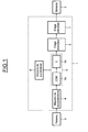
- the device 1 comprises connection means 4 making it possible to connect the charging device 1 to the supply network 3, a filtering stage 5 making it possible to filter the current of the supply network 3 taken by the device 1, a step-down step of voltage 6 connected to the output of the filtering stage 5 and for rectifying the alternating current from the supply network 3, and a voltage booster stage 7 coupled between the step-down stage 6 and the battery 2 .
- the filtering means 5 comprise an electromagnetic compatibility (EMC) filter 5a and a capacitive assembly 5b.
- EMC electromagnetic compatibility
- the EMC filter 5a is, for example, an inductance and common-mode capacitor filter for filtering the current pulses generated by the transistors of the voltage step 6 and output step 7 stages of the device 1.
- the filtering means 5 enable the current thus absorbed to be filtered so that the current satisfies the network connection constraints imposed by the network operators, in terms of harmonics as well as those of the automotive field.
- the capacitive assembly 5b comprises capacitors coupled in a so-called "star” arrangement so as to have two capacitors coupled between each phase.
- a so-called “star” capacitors it is also possible to arrange the capacitors 5b in a so-called “triangle” arrangement (not shown), that is to say by arranging the capacitors between each phase. and the neutral at the output of the filtering means 5a CEM. This decreases the current value passing through them.
- the device 1 also comprises monitoring means 8 of the capacitive assembly 5b able to detect a deviation of the value of at least one capacitance of the capacitive assembly 5b.
- the voltage booster stage 7 is connected to the voltage step-down stage 6 via an inductive element 9 symbolized in the figure by a resistor Rd arranged in series with an induction coil Ld.
- terminal B 3 In single-phase charging, terminal B 3 is not coupled to the supply network.
- the branch coupled to the terminal B 3 is considered only in the case of a three-phase charging, it has been shown in dashed lines.
- the other elements of the electrical circuit shown in dotted lines are elements that are used only in the context of a coupling to a three-phase power supply network.
- the voltage step-down stage 6 is coupled to the filtering stage 5 by the points D 1 , D 2 and D 3 .
- This comprises three parallel branches 6a. 6b and 6c each carrying two switches S 1 , S 2 or S 3 controlled by a control unit 12.
- the common ends of the branches 6, 7 and 8 constitute two output terminals of the voltage step-down device 6.
- One of the terminals is connected to the "-" terminal of the battery 2 as well as to a first input 10 of the The other of these terminals is connected to a first terminal of the electrical machine 9, the other terminal of which is connected to a second input 11 of the voltage booster 7.
- the device 1 comprises a first current sensor 13, a second current sensor 14, and a third current sensor 15 able respectively to measure the current I 1 flowing on the branch coupled to the first terminal B 1 , the current I 2 flowing on the branch coupled to the second terminal B 2 , and the current I 3 flowing on the branch coupled to the third terminal B 3 .
- the device also comprises a first voltage sensor 16, a second voltage sensor 17, and a third voltage sensor 18 able respectively to measure the voltage V 1 between the first terminal B 1 and the second terminal B 2 , the voltage V 2 between the second terminal B 2 and the third terminal B 3 , and the voltage V 3 between the first terminal B 1 and the third terminal B 3 .
- the voltage sensors 16 to 18, and the current sensors 13 to 15 are coupled to the monitoring means 8 of the device.
- the measurement of the first current sensor 13 and the measurement of the first voltage sensor 16 are used to monitor the state of the capacity capacitors C of the capacitive assembly 5b.
- the measurement of the current sensor 14 can be used instead of the measurement of the current sensor 13 in case of failure of the latter.
- FIG 3 On the figure 3 are illustrated in more detail the monitoring means 8 of the device 1 for charging a battery 2 of the figure 1 .
- the monitoring means 8 comprise activation means 19 able to activate the monitoring means 8 when the device is connected to the supply network 3 and before the charge has started.
- the monitoring means 8 comprise means 20 for determining the effective values receiving as input the values of the voltages V 1 , V 2 , V 3 measured respectively by the first, second and third voltage sensors 16, 17, 18 and the currents intensities. current I 1 , I 2 , I 3 measured respectively by the first, second and third current sensors 13, 14, 15.
- the means 20 for determining the effective values output the effective values V 1e , V 2e , V 3e of the voltages V 1 , V 2 , V 3 as well as the effective values I 1e , I 2e , I 3e of currents I 1 , I 2 , I 3 .
- the monitoring means 8 comprise calculation means 21 of at least one parameter representative of the capacitive assembly 5b coupled to output means 22 for determining the state of the capacitance capacitors C of the capacitive assembly 5b from calculated representative parameters.
- the calculation means 21 receive as inputs the voltage values V 1e , V 2e , V 3e and current I Ie , I 2e , I 3e , and calculate for each phase, that is to say for each coupled branch at a terminal B 1 , B 2 or B 3 , at least one parameter representative of the capacitive assembly 5b.
- the monitoring means 8 are activated before the start of charge of the battery 2 by the activation means 19.
- I 1 I c1
- I 2 I c2
- I 3 I c3 (see in particular figure 2 ).
- I e the effective value of the current of a phase (ie I e1 , I e2 , or I e3 ), V e the value effective of the voltage between two phases comprising this phase, k a coefficient dependent on the CEM filter 5a, and C the value of the equivalent capacitance coupled between the two phases.
- k ⁇ C is constant unless a capacity is faulted.
- k ⁇ C is subsequently named capacitive constant. This term is obtained by calibration in a preliminary step.
- the calculation means 21 calculate the following pair of representative parameters: I 1 ⁇ e f ⁇ V 1 ⁇ e and I 1 ⁇ e f ⁇ V 3 ⁇ e
- the calculation means 21 calculate the following pair of representative parameters: I 2 ⁇ e f ⁇ V 2 ⁇ e and I 2 ⁇ e f ⁇ V 1 ⁇ e
- the calculation means 21 calculate the pair of representative parameters as follows: I 3 ⁇ e f ⁇ V 3 ⁇ e and I 3 ⁇ e f ⁇ V 2 ⁇ e
- the three pairs of parameters representative of the state of the capacitive assembly 5b are transmitted to the means 22 for determining the state of the capacitances C of the capacitive assembly 5b.
- the use of a pair of representative parameters per phase makes it possible to determine which capacitance of the capacitive assembly 5b is faulty.
- each phase thus obtaining a pair of absolute values delivered to a comparator 24.
- Each absolute value of the pair is compared to a threshold of variation. If at least one absolute value of the result is greater than the variation threshold, the capacitance C coupled between the phase and the neutral point is degraded.
- the three comparators 24 are coupled to a processing module 25 capable of outputting a control signal to limit the charging performance of the battery 2 and a warning signal so as to warn the user of the degradation of the battery. the capacitive assembly 5b and the need to change it.
- This representative parameter is delivered by the calculation means 21 to a calculation module 23 to calculate the absolute value: I 1 ⁇ e f ⁇ V e - k ⁇ ⁇ ⁇ VS
- the absolute value thus calculated is delivered to a comparator 24 so as to be compared with the threshold of variation. If the absolute value is lower than the variation threshold, the capacity capacitors C coupled in between the two phases are not considered as degraded. Otherwise a signal is delivered to the processing module 25 to control a load limitation and the user's warning.
- monitoring means comprise a charging activation module 26 able to control the calculation means 21.
- I ⁇ I ⁇ f + VS 2 ⁇ ⁇ U ⁇ VS ⁇ t
- I f the current flowing between the point D 1 and the step-down stage 6, and U c the voltage across the two capacitors coupled between the terminals B 1 and B 2 .
- the control unit 12 controls the charging of the battery so that U c and I f are in phase.
- I f being piloted, its value is known and corresponds to a piece of software.
- I ⁇ sin ⁇ ⁇ t - ⁇ I f ⁇ ⁇ sin ⁇ ⁇ t + ⁇ ⁇ VS ⁇ k V 1 2 ⁇ cos ⁇ ⁇ t
- This representative parameter is then delivered to a calculation module 23 which calculates the following absolute value: 2 ⁇ I 1 ⁇ e 2 - I f ⁇ e 2 V 1 ⁇ e 2 - VS 2 ⁇ ⁇ 2 ⁇ k 2 ⁇ f 2
- the absolute value thus calculated is delivered to a comparator 24 to be compared with a threshold of variation. If the absolute value is greater than the variation threshold, one of the capacitors C coupled between the two terminals B 1 and B 2 is degraded.
- the processing module 25 When a degradation of a capacitance is thus detected by at least one comparator 24, the processing module 25 outputs a control signal to limit the charging performance of the battery 2 and a warning signal so as to warn the user of the degradation of the capacitive assembly 5b and the need to change it.
- FIG 4 is schematically represented a flowchart of a control method of a charging device (1) according to an embodiment.
- a first step 400 the connection of the charging device to a supply network 3 is detected by measuring the current and voltage at the input terminals B 1 , B 2 , B 3 of the device 1 produced by the current sensors. 13 to 15 and the voltage sensors 16 to 18.
- a next step 410 it is determined from the voltage and current measurements whether the connected supply network 3 is a single-phase supply network is three-phase or single-phase.
- a next step 420 in the case of a single-phase network and 420 'in the case of a three-phase network it is determined whether the charge of the battery 2 has started. If it has not started, in the following step 430 is activated in the case of a single-phase network and 430 'in the case of a three-phase network, the monitoring means 8 and a representative parameter is calculated if the network power supply is single-phase 3, and three pairs of representative parameters if the power supply network 3 is three-phase.
- a next step 440 in the case of a single-phase network and 440 'in the case of a three-phase network, the absolute value of the difference between the representative parameter (s) and the capacitive constant.
- a control signal is delivered to limit the charging performance of the battery 2.
- a warning signal is delivered so as to warn the user of the degradation of the capacitive assembly 5b.
- a control signal is provided to limit the charging performance of the battery 2 and a warning signal is output to warn the user of the degradation of the capacitive assembly 5b.
- step 420 it is detected that the charge of the battery 2 has already begun, it is expected to activate the monitoring load by the activation means in charge 26. In the case of a connection to a network three-phase power supply (step 420 '), there is no monitoring load.
- the invention thus proposes a simple and inexpensive monitoring device and method, making it possible to detect a possible deviation of one or more capacitances of the capacitive filter coupled to a single-phase or three-phase network so as to reduce the charging performance and to inform the user that the capacitive filter must be replaced, or even prohibit the charging of the battery of the electric vehicle if this deterioration is very important.
Landscapes
- Engineering & Computer Science (AREA)
- Power Engineering (AREA)
- Transportation (AREA)
- Mechanical Engineering (AREA)
- Life Sciences & Earth Sciences (AREA)
- Sustainable Development (AREA)
- Sustainable Energy (AREA)
- Manufacturing & Machinery (AREA)
- Chemical & Material Sciences (AREA)
- Chemical Kinetics & Catalysis (AREA)
- Electrochemistry (AREA)
- General Chemical & Material Sciences (AREA)
- Physics & Mathematics (AREA)
- General Physics & Mathematics (AREA)
- Charge And Discharge Circuits For Batteries Or The Like (AREA)
- Electric Propulsion And Braking For Vehicles (AREA)
Description
- L'invention concerne les moyens de filtrage du courant d'entrée d'un dispositif de charge de batterie haute tension, notamment d'un véhicule automobile à traction électrique, à partir d'un réseau d'alimentation monophasé ou triphasé, et plus particulièrement la surveillance de l'état des moyens de filtrage.
- Dans des systèmes de recharge de batterie à haute tension, la puissance électrique du réseau est amenée à la batterie successivement au travers de deux convertisseurs : un abaisseur de tension (« buck ») et un élévateur de tension (« boost »). Ces deux convertisseurs permettent respectivement d'abaisser et d'élever le rapport de tension entre leur borne de sortie et leur borne d'entrée, en ouvrant et en fermant successivement une série d'interrupteurs, à une fréquence qui est commandée en fonction du courant de sortie, et/ou de la tension de sortie souhaitée.
- De tels systèmes de recharge sont par exemple décrits dans la demande de brevet
FR 2 943 188 - Le hachage du courant tiré du réseau d'alimentation induit des composantes à haute fréquence dans le courant prélevé, c'est-à-dire des harmoniques d'ordre supérieur au fondamental du réseau de distribution qui est classiquement à 50 Hz.
- Les fournisseurs d'énergie électrique imposant une norme sur les harmoniques du courant prélevé, un tel système de recharge comporte également des moyens de filtrage de type RLC (Résistif-Inductif-Capacitif) à l'entrée de l'abaisseur de tension.
- Les moyens de filtrage comprennent généralement un filtre de compatibilité électromagnétique (CEM), ainsi qu'un filtre de type capacitif comportant des capacités de filtrage disposées « en étoile » de manière à effectuer un filtrage entre chaque phase du réseau de distribution. Le filtre CEM est, par exemple, un filtre à inductances et à capacités de mode commun permettant de filtrer les impulsions de courant générées par les transistors de l'étage abaisseur de tension et de l'étage élévateur de tension du système de recharge. Les moyens de filtrage permettent ainsi de filtrer le courant absorbé de sorte que le courant satisfasse aux contraintes de raccordement au réseau imposées par les exploitants de réseaux, en termes d'harmoniques ainsi que celles du domaine automobile.
- Dans la configuration prenant en compte le neutre, le filtre capacitif comprend également une capacité de filtrage du neutre disposée entre le fil du neutre et le point commun des capacités de filtrage. Cette dernière capacité permet d'effectuer un filtrage entre le fil du neutre et les phases.
- Cependant, un tel filtre capacitif peut se dégrader, par exemple dans le cas d'une dégradation ou d'un vieillissement d'une ou plusieurs capacités. Une telle dégradation du filtre capacitif peut alors entraîner une inefficacité de filtrage et un déséquilibre du réseau de distribution.
- Pour surveiller le filtre capacitif, on peut se référer au document
US 4 419 621 qui décrit un système réalisant une surveillance d'un filtre capacitif couplé à une batterie. Le système de surveillance utilise une analyse fréquentielle des signaux. Cependant, un tel dispositif présente une complexité élevée pour une simple détection de défaut. - On connaît également du document
US 5 880 589 un dispositif permettant de réaliser un diagnostique d'une capacité électrolytique en fonctionnement. - On pourra également se référer au document
US 2010/0321038 qui décrit l'utilisation d'une équation spécifique permettant de calculer précisément la valeur de chaque capacité du système. Cependant, un tel dispositif présente également une complexité élevée pour une simple détection de défaut, et un prix de revient élevé. - L'invention vise à pallier les inconvénients mentionnés ci-dessus en proposant un dispositif selon la revendication 1 et un procédé de surveillance simple et peu couteux selon la revendication 10, permettant de détecter une éventuelle déviation d'une ou plusieurs des capacités du filtre capacitif couplé à un réseau monophasé ou triphasé de manière à réduire les performances de charge et à informer l'utilisateur que le filtre capacitif doit être remplacé, voire même à interdire la charge de la batterie du véhicule électrique si cette détérioration est très importante.
- Selon un aspect, il est proposé, dans un mode de réalisation, un dispositif de charge d'une batterie, notamment une batterie d'un véhicule automobile à traction électrique, à partir d'un réseau d'alimentation triphasé ou monophasé, comprenant un étage de filtrage comportant un ensemble capacitif et destiné à être raccordé au réseau d'alimentation. Dans un mode de réalisation, le dispositif peut comporter un étage abaisseur de tension raccordé à l'étage de filtrage, et un étage élévateur de tension destiné à être raccordé à la batterie et couplé à l'étage abaisseur de tension.
- Selon une caractéristique générale, le dispositif comprend des moyens de surveillance de l'ensemble capacitif apte à détecter une déviation de la valeur de la capacité d'au moins une capacité de l'ensemble capacitif à partir de tensions et de courants mesurés en entrée de l'étage de filtrage.
- De préférence, les moyens de surveillance comprennent des moyens de détermination de valeurs caractéristiques des tensions et des courants mesurés, des moyens de calcul d'au moins un paramètre représentatif de l'ensemble capacitif à partir de ces valeurs caractéristiques de tension et de courant, des moyens de détermination de l'état des condensateurs de l'ensemble capacitif à partir du paramètre représentatif calculé, et des moyens de traitement aptes à délivrer un signal de commande et/ou un signal d'avertissement de manière à avertir l'utilisateur de la dégradation de l'ensemble capacitif.
- Les valeurs caractéristiques des tensions et des courants peuvent être par exemple les valeurs efficaces de ces tensions et courants.
- Dans un mode de réalisation, le signal de commande est capable de provoquer une limitation des performances de charge de la batterie.
- Avantageusement, les moyens de détermination de l'état des condensateurs peuvent comprendre au moins un module de calcul apte à calculer la valeur absolue de la différence entre le paramètre représentatif et une constante capacitive, et au moins un module de comparaison apte à comparer ladite valeur absolue calculée à un seuil de variation.
- Les moyens de surveillance peuvent également comprendre des moyens d'activation aptes à activer les moyens de surveillance lorsque le dispositif est raccordé au réseau d'alimentation et avant le début de la charge de la batterie, le paramètre représentatif étant proportionnel, lorsque les moyens de surveillance sont activés avant le début de la charge de la batterie, au rapport entre la valeur du courant efficace d'une première phase et le produit de la fréquence avec la valeur de la tension efficace entre la première phase et une autre phase.
- De préférence, les moyens de surveillance peuvent comprendre des moyens d'activation en charge aptes à activer les moyens de surveillance lorsque la batterie est en charge sur un réseau d'alimentation monophasé, le paramètre représentatif correspondant, lorsque les moyens de surveillance sont activés après le début d'une charge sur un réseau monophasé, au rapport entre, d'une part, la différence entre le double du carré de la valeur efficace du courant d'alimentation et le carré de la valeur efficace du courant en entrée de l'étage abaisseur de tension, et, d'autre part, le produit de la tension efficace aux bornes du réseau d'alimentation et de la fréquence du réseau d'alimentation.
- Selon un autre aspect, il est proposé un véhicule automobile à traction au moins partiellement électrique, comprenant une machine électrique couplée à des roues motrices et un étage onduleur apte à alimenter la machine électrique à partir d'une batterie, caractérisé en ce qu'il comprend un dispositif de charge de la batterie tel que défini ci-dessus.
- Selon un autre aspect, il est proposé, dans un mode de mise en oeuvre, un procédé de commande d'un dispositif de charge d'une batterie, notamment une batterie d'un véhicule automobile à traction électrique, à partir d'un réseau d'alimentation triphasé ou monophasé, dans lequel on filtre au moins une tension d'entrée issue dudit réseau d'alimentation à l'aide d'un étage de filtrage comprenant un ensemble capacitif, on mesure le courant d'alimentation en entrée de l'étage de filtrage, et l'on mesure la tension d'alimentation en entrée de l'étage de filtrage.
- Selon une caractéristique générale, on surveille l'état des condensateurs de l'ensemble capacitif à partir de la variation d'au moins un paramètre représentatif de l'ensemble capacitif à partir des tensions et des courants mesurés en entrée de l'étage de filtrage.
- De préférence, le procédé comprend une détermination des valeurs efficaces des tensions et des courants mesurés, un calcul d'au moins un paramètre représentatif de l'ensemble capacitif à partir des valeurs efficaces de tension et de courant, et une détermination de l'état des condensateurs de l'ensemble capacitif à partir du paramètre représentatif ainsi calculé, et une délivrance d'un signal de commande pour limiter les performances de charge de la batterie et d'un signal d'avertissement de manière à avertir l'utilisateur de la dégradation de l'ensemble capacitif.
- La détermination de l'état des condensateurs de l'ensemble capacitif peut avantageusement comprendre au moins un calcul de la valeur absolue de la différence entre une constante capacitive et un desdits paramètres représentatifs de l'ensemble capacitif, et une comparaison du résultat de la soustraction calculée à un seuil de variation.
- De préférence, le paramètre représentatif correspond, lorsque les moyens de surveillance sont activés avant le début de la charge de la batterie, au rapport entre la valeur du courant efficace d'une première phase et le produit de la fréquence avec la valeur de la tension efficace entre la première phase et une autre phase et, lorsque les moyens de surveillance sont activés après le début d'une charge sur un réseau monophasé, au rapport entre, d'une part, la différence entre deux fois le carré de la valeur efficace du courant d'alimentation et le carré de la valeur efficace du courant en entrée de l'étage abaisseur de tension, et, d'autre part, le produit de la tension efficace aux bornes du réseau d'alimentation et la fréquence du réseau d'alimentation.
- D'autres avantages et caractéristiques de l'invention apparaîtront à l'examen de la description détaillée d'un mode de mise en oeuvre et d'un mode de réalisation, nullement limitatifs, et des dessins annexés, sur lesquels :
- la
figure 1 représente de manière schématique un dispositif de charge d'une batterie d'un véhicule automobile selon un mode de réalisation ; - la
figure 2 illustre, de manière plus détaillée, un mode de réalisation du dispositif de charge de lafigure 1 ; - la
figure 3 illustre de manière plus détaillée les moyens de surveillance du dispositif de charge de lafigure 1 ; - la
figure 4 présente un organigramme d'un procédé de commande du dispositif de charge selon un mode de mise en oeuvre. - Sur la
figure 1 , est représenté, de manière schématique, un dispositif 1 de charge d'une batterie 2 d'un véhicule automobile destiné à être raccordé à un réseau d'alimentation 3 triphasé ou monophasé pour recharger la batterie 2. - Le dispositif 1 comprend des moyens de raccordement 4 permettant de raccorder le dispositif 1 de charge au réseau d'alimentation 3, un étage de filtrage 5 permettant de filtrer le courant du réseau d'alimentation 3 prélevé par le dispositif 1, un étage abaisseur de tension 6 raccordé à la sortie de l'étage de filtrage 5 et permettant de redresser le courant alternatif issu du réseau d'alimentation 3, ainsi qu'un étage élévateur de tension 7 couplé entre l'étage abaisseur de tension 6 et la batterie 2.
- Les moyens de filtrage 5 comprennent un filtre 5a de compatibilité électromagnétique (CEM), ainsi qu'un ensemble capacitif 5b. Le filtre 5a CEM est, par exemple, un filtre à inductances et à capacités de mode commun permettant de filtrer les impulsions de courant générées par les transistors des étages abaisseur de tension 6 et élévateur de sortie 7 du dispositif 1. Les moyens de filtrage 5 permettent de filtrer le courant ainsi absorbé de sorte que le courant satisfasse aux contraintes de raccordement au réseau imposées par les exploitants de réseaux, en termes d'harmoniques ainsi que celles du domaine automobile.
- L'ensemble capacitif 5b comprend des capacités couplées selon une disposition dite « en étoile » de manière à avoir deux capacités couplées entre chaque phase. Au lieu d'une disposition des capacités dite « en étoile », il est également possible de disposer les capacités 5b selon une disposition dite « en triangle » (non représentée), c'est-à-dire en disposant les capacités entre chaque phase et le neutre à la sortie des moyens de filtrage 5a CEM. On diminue ainsi la valeur de courant qui les traverse.
- Le dispositif 1 comprend également des moyens de surveillance 8 de l'ensemble capacitif 5b aptes à détecter une déviation de la valeur d'au moins une capacité de l'ensemble capacitif 5b.
- Sur la
figure 2 est illustré de manière plus détaillée le dispositif de charge de lafigure 1 . - L'étage élévateur de tension 7 est raccordé à l'étage abaisseur de tension 6 via un élément inductif 9 symbolisé sur la figure par une résistance Rd disposée en série avec une bobine d'induction Ld.
- Le dispositif 1 pouvant être couplé à une alimentation aussi bien triphasée que monophasée, les moyens de raccordement 4 comprennent trois bornes B1, B2, B3 couplées en entrée de l'étage de filtrage 5, et aptes à être couplées au réseau d'alimentation 3. En recharge triphasé, les trois bornes B1, B2, B3 sont couplées à un réseau d'alimentation triphasé. En recharge monophasée, seules les entrées B1 et B2 sont couplées à un réseau d'alimentation monophasé délivrant une tension d'entrée V1 et un courant d'entrée I1. Chaque borne d'entrée B1, B2 et B3 est raccordée à une branche de filtrage du filtre CEM 5a. Chaque branche de filtrage du filtre CEM 5a comprend deux branches en parallèle, portant l'une une inductance de valeur L2 et l'autre portant en série une inductance de valeur L1 et une résistance de valeur R.
- Ces deux branches de filtrage sont chacune couplées en sortie à un condensateur de capacité C de l'ensemble capacitif 5b également couplé à la masse, en des points respectivement nommés D1, D2, D3 pour chacune des branches de filtrage du filtre CEM 5a. Les différents condensateurs de capacité C sont tous reliés à un point commun ou point neutre noté N sur la
figure 2 . L'ensemble des résistances de valeurs R. des inductances de valeurs L1 ou L2, et des condensateurs de capacité C constitue un filtre de type RLC à l'entrée de l'abaisseur de tension 3. - En recharge monophasée, la borne B3 n'est pas couplée au réseau d'alimentation. La branche couplée à la borne B3 n'étant considérée que dans le cas d'une recharge triphasée, celle-ci a été représentée en pointillés. Les autres éléments du circuit électrique représentés en pointillés sont des éléments qui ne sont utilisés que dans le cadre d'un couplage à un réseau d'alimentation triphasé.
- L'étage abaisseur de tension 6 est couplé à l'étage de filtrage 5 par les points D1, D2 et D3. Celui-ci comprend trois branches parallèles 6a. 6b et 6c portant chacune deux interrupteurs S1, S2 ou S3 commandés par une unité de commande 12.
- Les extrémités communes des branches 6, 7 et 8 constituent deux bornes de sortie de l'abaisseur de tension 6. L'une des bornes est reliée à la borne « - » de la batterie 2 ainsi qu'à une première entrée 10 de l'étage élévateur de tension 7. L'autre de ces bornes est connectée à une première borne de la machine électrique 9, dont l'autre borne est connectée à une seconde entrée 11 de l'élévateur de tension 7.
- L'étage élévateur de tension 7 comprend deux interrupteurs S4 et S5 pilotables par l'unité de commande 12 de manière indépendante. Ces deux interrupteurs S4 et S5 sont situés sur une branche reliant la première entrée 10 de l'étage élévateur de tension 7 et la borne « + » de la batterie 2. La seconde entrée 11 de l'étage élévateur de tension 7, à laquelle est connectée la machine électrique 9, est connectée entre les deux interrupteurs S4 et S5, l'interrupteur S4 étant couplé entre la seconde entrée 11 et la borne « + » de la batterie 2, et l'interrupteur S5 étant couplé entre la première entrée 10 et la seconde entrée 11.
- Le dispositif 1 comprend un premier capteur de courant 13, un second capteur de courant 14, et un troisième capteur de courant 15 aptes à mesurer respectivement le courant I1 circulant sur la branche couplée à la première borne B1, le courant I2 circulant sur la branche couplée à la seconde borne B2, et le courant I3 circulant sur la branche couplée à la troisième borne B3.
- Le dispositif comprend également un premier capteur de tension 16, un second capteur de tension 17, et un troisième capteur de tension 18 aptes à mesurer respectivement la tension V1 entre la première borne B1 et la seconde borne B2, la tension V2 entre la seconde borne B2 et la troisième borne B3, et la tension V3 entre la première borne B1 et la troisième borne B3.
- Les capteurs de tension 16 à 18, et les capteurs de courant 13 à 15 sont couplés au moyen de surveillance 8 du dispositif. Dans le cas d'une recharge sur un réseau d'alimentation monophasé, seule la mesure du premier capteur de courant 13 et la mesure du premier capteur de tension 16 sont utilisées pour surveiller l'état des condensateurs de capacité C de l'ensemble capacitif 5b. On notera que la mesure du capteur de courant 14 peut être utilisée à la place de la mesure du capteur de courant 13 en cas de défaillance de ce dernier.
- Sur la
figure 3 sont illustrés de manière plus détaillée les moyens de surveillance 8 du dispositif 1 de charge d'une batterie 2 de lafigure 1 . - Les moyens de surveillance 8 comprennent des moyens d'activation 19 aptes à activer les moyens de surveillance 8 lorsque le dispositif est raccordé au réseau d'alimentation 3 et avant que la charge n'ait débuté.
- Les moyens de surveillance 8 comprennent des moyens 20 de détermination des valeurs efficaces recevant en entrée les valeurs des tensions V1, V2, V3 mesurées respectivement par les premier, second et troisième capteurs de tension 16, 17, 18 et les intensités des courants I1, I2, I3 mesurées respectivement par les premier, second et troisième capteurs de courant 13, 14, 15. Les moyens 20 de détermination des valeurs efficaces délivrent en sortie les valeurs efficaces V1e, V2e, V3e des tensions V1, V2, V3 ainsi que les valeurs efficaces I1e, I2e, I3e des courants I1, I2, I3.
- Les moyens d'activation 19 sont raccordés aux moyens 20 de détermination de sorte que dès qu'une mesure de courant correspondant au raccordement d'un réseau d'alimentation 3 au dispositif de charge 1 est délivrée par l'un des capteurs de courant 13 à 15 aux moyens de détermination 20, les moyens d'activation activent les moyens 20 de détermination.
- Les moyens de surveillance 8 comprennent des moyens de calcul 21 d'au moins un paramètre représentatif de l'ensemble capacitif 5b couplés en sortie à des moyens de détermination 22 de l'état des condensateurs de capacité C de l'ensemble capacitif 5b à partir des paramètres représentatifs calculés.
- Les moyens de calcul 21 reçoivent en entrées les valeurs efficaces de tension V1e, V2e, V3e et de courant I1e, I2e, I3e, et calculent pour chaque phase, c'est-à-dire pour chaque branche couplée à une borne B1, B2 ou B3, au moins un paramètre représentatif de l'ensemble capacitif 5b.
- Dans le cas où le dispositif de charge 1 est raccordé à un réseau d'alimentation 3 triphasé, les moyens de surveillance 8 sont activés avant le début de charge de la batterie 2 par les moyens d'activation 19. On a alors I1= Ic1, I2=Ic2, I3=Ic3 (voir notamment
figure 2 ). L'ensemble capacitif 5b constituant un système équilibré, c'est-à-dire que les capacités couplées entre deux phases ont la même valeur que les capacités couplées entre chaque autre paire de phases, la relation suivante est vérifiée pour chaque phase :
- Avec f la fréquence (mesurée) du courant distribuée par le réseau d'alimentation 3, Ie la valeur efficace du courant d'une phase (c'est à dire Ie1, Ie2, ou Ie3), Ve la valeur efficace de la tension entre deux phases comprenant cette phase, k un coefficient dépendant du filtre CEM 5a, et C la valeur de la capacité équivalente couplée entre les deux phases. Dans un système équilibré, toutes les capacités étant égales, le terme kπC est constant à moins qu'une capacité soit mise en défaut. Le terme kπC est nommé par la suite constante capacitive. Ce terme est obtenu par calibration dans une étape préliminaire.
- Pour contrôler l'état de la capacité couplée entre la première phase sur laquelle circule le courant I1 et le point neutre, les moyens de calcul 21 calculent la paire de paramètres représentatifs suivants :

- De la même manière, pour contrôler l'état de la capacité couplée entre la seconde phase sur laquelle circule le courant I2 et la masse, les moyens de calcul 21 calculent la paire de paramètres représentatifs suivants :

- Et pour contrôler l'état de la capacité couplée entre la troisième phase sur laquelle circule le courant I3 et le point neutre, les moyens de calcul 21 calculent la paire de paramètres représentatifs suivants :

- Les trois paires de paramètres représentatifs de l'état de l'ensemble capacitif 5b sont transmis aux moyens de détermination 22 de l'état des capacités C de l'ensemble capacitif 5b. L'utilisation d'une paire de paramètres représentatifs par phase permet de déterminer quelle capacité de l'ensemble capacitif 5b est défaillante.
- Les moyens de détermination 22 comprennent pour chaque paramètre représentatif reçu un module de calcul 23 délivrant en sortie la valeur absolue du résultat de la différence entre le paramètre représentatif et la constante capacitive kπC, soit :

- Pour chaque phase, on obtient ainsi une paire de valeurs absolues délivrée à un comparateur 24. Chaque valeur absolue de la paire est comparée à un seuil de variation. Si au moins une valeur absolue du résultat est supérieure au seuil de variation, la capacité C couplée entre la phase et le point neutre est dégradée.
- Les trois comparateurs 24 sont couplés en sortie à un module de traitement 25 capable de délivrer en sortie un signal de commande pour limiter les performances de charge de la batterie 2 et un signal d'avertissement de manière à avertir l'utilisateur de la dégradation de l'ensemble capacitif 5b et de la nécessité de procéder à son changement.
- Dans le cas où le dispositif de charge 1 est raccordé à un réseau d'alimentation 3 monophasé par les bornes B1 et B2, un seul paramètre représentatif est calculé par les moyens de calcul 21 :

- Ce paramètre représentatif est délivré par les moyens de calcul 21 à un module de calcul 23 pour calculer la valeur absolue :

- La valeur absolue ainsi calculée est délivrée à un comparateur 24 de manière à être comparée au seuil de variation. Si la valeur absolue est inférieure au seuil de variation, les condensateurs de capacité C couplés en entre les deux phases ne sont pas considérés comme dégradées. Sinon un signal est délivré au module de traitement 25 pour commander une limitation de la charge et l'avertissement de l'utilisateur.
- Dans le cas où le dispositif est raccordé à un réseau d'alimentation 3 monophasé, il est également possible de réaliser une surveillance alors que la batterie 2 est en charge. Pour cela, les moyens de surveillance comprennent un module d'activation en charge 26 apte à commander les moyens de calcul 21.
- Dans le cas où la batterie 2 est en charge, la relation suivante est vérifiée :

- Avec If le courant circulant entre le point D1 et l'étage abaisseur de tension 6, et Uc la tension aux bornes des deux capacités couplées entre les bornes B1 et B2. L'unité de commande 12 pilote la charge de la batterie de telle manière que Uc et If soient en phase. If étant piloté, sa valeur est connue et correspond à une donnée logicielle.
- Le courant If et la tension Uc étant en phase, la relation précédente peut s'écrire :

- ϕ étant un déphasage dû au filtre CEM et avec l'approximation : Uc = kV1.
- En considérant les valeurs efficaces de courant et de tension, on peut en déduire l'expression suivante :
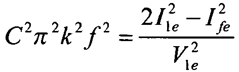
- Avec f la fréquence du courant distribuée par le réseau d'alimentation 3 monophasé, I1e la valeur efficace du courant en entrée des moyens de filtrage 5, V1e la valeur efficace de la tension entre les deux bornes B1 et B2, et k un coefficient dépendant du filtre CEM 5a.
- Pour surveiller l'état de l'ensemble capacitif 5b lors d'une charge depuis un réseau d'alimentation 3 monophasé, les moyens de calcul 21 activés par le module d'activation en charge 26 calculent le paramètre représentatif suivant :

- Ce paramètre représentatif est alors délivré à un module de calcul 23 qui calcule la valeur absolue suivante :

- La valeur absolue ainsi calculée est délivrée à un comparateur 24 pour être comparée à un seuil de variation. Si la valeur absolue est supérieure au seuil de variation, une des capacités C couplées entre les deux bornes B1 et B2 est dégradée.
- Lorsqu'une dégradation d'une capacité est ainsi détectée par au moins un comparateur 24, le module de traitement 25 délivre en sortie un signal de commande pour limiter les performances de charge de la batterie 2 et un signal d'avertissement de manière à avertir l'utilisateur de la dégradation de l'ensemble capacitif 5b et de la nécessité de procéder à son changement.
- Sur la
figure 4 est représenté de manière schématique un organigramme d'un procédé de commande d'un dispositif de charge (1) selon un mode de mise en oeuvre. - Dans une première étape 400 on détecte le raccordement du dispositif de charge à un réseau d'alimentation 3 grâce aux mesures de courant et de tension aux bornes d'entrée B1, B2, B3 du dispositif 1 réalisées par les capteurs de courant 13 à 15 et les capteurs de tension 16 à 18.
- Dans une étape suivante 410, on détermine à partir des mesures de tension et de courant si le réseau d'alimentation raccordé 3 est un réseau d'alimentation monophasé est triphasé ou monophasé.
- Dans une étape suivante 420 dans le cas d'un réseau monophasé et 420' dans le cas d'un réseau triphasé, on détermine si la charge de la batterie 2 a débuté. Si elle n'a pas commencée, on active, dans une étape suivante 430 dans le cas d'un réseau monophasé et 430' dans le cas d'un réseau triphasé, les moyens de surveillance 8 et on calcule un paramètre représentatif si le réseau d'alimentation est monophasé 3, et trois paires de paramètres représentatifs si le réseau d'alimentation 3 est triphasé.
- Dans une étape suivante 440, dans le cas d'un réseau monophasé et 440' dans le cas d'un réseau triphasé, on calcule la valeur absolue de la différence entre le ou les paramètres représentatifs et la constante capacitive.
- Dans une étape suivante 450, dans le cas d'un réseau monophasé et 450' dans le cas d'un réseau triphasé, on détecte l'existence d'une dégradation d'un condensateur à partir de la comparaison de la ou des valeurs absolues calculées à un seuil de variation.
- Dans le cas d'un réseau monophasé, si la valeur absolue calculée est supérieure au seuil de variation, alors, dans une étape suivante 460, un condensateur au moins de l'ensemble capacitif 5b est dégradé et un signal de commande est délivré pour limiter les performances de charge de la batterie 2. Un signal d'avertissement est délivré de manière à avertir l'utilisateur de la dégradation de l'ensemble capacitif 5b.
- Dans le cas d'un réseau triphasé, si au moins une valeur absolue d'une paire de paramètres représentatifs est supérieure au seuil de variation, alors le condensateur de l'ensemble capacitif 5b couplé entre la phase considérée et le point neutre est dégradé. Dans une étape suivante 460', un signal de commande est délivré pour limiter les performances de charge de la batterie 2 et un signal d'avertissement est délivré de manière à avertir l'utilisateur de la dégradation de l'ensemble capacitif 5b.
- Si aucun défaut n'est détecté aucun signal n'est émis.
- Si dans l'étape 420, on détecte que la charge de la batterie 2 a déjà débuté, on attend l'activation de la surveillance en charge par les moyens d'activation en charge 26. Dans le cas d'un raccordement à un réseau d'alimentation triphasé (étape 420'), on ne réalise pas de surveillance en charge.
- L'invention propose ainsi un dispositif et un procédé de surveillance simples et peu coûteux, permettant de détecter une éventuelle déviation d'une ou plusieurs des capacités du filtre capacitif couplé à un réseau monophasé ou triphasé de manière à réduire les performances de charge et à informer l'utilisateur que le filtre capacitif doit être remplacé, voire même à interdire la charge de la batterie du véhicule électrique si cette détérioration est très importante.
Claims (13)
- Dispositif (1) de charge d'une batterie (2), notamment une batterie d'un véhicule automobile à traction électrique, à partir d'un réseau d'alimentation (3) triphasé ou monophasé, comprenant un étage de filtrage (5) comportant un ensemble capacitif (5b) et destiné à être raccordé au réseau d'alimentation (3), caractérisé en ce qu'il comprend des moyens de surveillance (8) de l'ensemble capacitif (5b) aptes à détecter une déviation de la valeur de la capacité d'au moins une capacité (C) de l'ensemble capacitif (5b) à partir de tensions et de courants mesurés en entrée (B1, B2, B3) de l'étage de filtrage (5).
- Dispositif selon la revendication 1, comportant en outre un étage abaisseur de tension (6) raccordé à l'étage de filtrage (5), et un étage élévateur de tension (7) destiné à être raccordé à la batterie (2) et couplé à l'étage abaisseur de tension (6).
- Dispositif (1) selon l'une des revendications 1 ou 2, caractérisé en ce que les moyens de surveillance (8) comprennent des moyens (20) de détermination de valeurs caractéristiques des tensions et des courants mesurés, des moyens de calcul (21) d'au moins un paramètre représentatif de l'ensemble capacitif à partir desdites valeurs caractéristiques de tension et de courant, des moyens de détermination (22) de l'état des condensateurs de l'ensemble capacitif (5b) à partir du paramètre représentatif, et des moyens de traitement (25) aptes à délivrer un signal de commande et/ou un signal d'avertissement de manière à avertir l'utilisateur de la dégradation de l'ensemble capacitif (5b).
- Dispositif selon la revendication 3, dans lequel les valeurs caractéristiques sont les valeurs efficaces.
- Dispositif selon l'une des revendications 3 ou 4, dans lequel le signal de commande est capable de limiter les performances de charge de la batterie.
- Dispositif (1) selon l'une des revendications 3 à 5, caractérisé en ce que les moyens de détermination (22) de l'état des condensateurs comprennent au moins un module de calcul (23) apte à calculer la différence entre le paramètre représentatif et une constante capacitive, et au moins un module de comparaison (24) apte à comparer ladite différence calculée à un seuil de variation.
- Dispositif (1) selon l'une des revendications précédentes, dans lequel les moyens de surveillance (8) comprennent des moyens d'activation (19) aptes à activer les moyens de surveillance (8) lorsque le dispositif (1) est raccordé au réseau d'alimentation (3) et avant le début de la charge de la batterie (2), le paramètre représentatif étant proportionnel, lorsque les moyens de surveillance (8) sont activés avant le début de la charge de la batterie (2), au rapport entre la valeur du courant efficace d'une première phase et le produit de la fréquence avec la valeur de la tension efficace entre la première phase et une autre phase.
- Dispositif (1) selon l'une des revendications précédentes, dans lequel les moyens de surveillance (8) comprennent des moyens d'activation en charge (26) aptes à activer les moyens de surveillance (8) lorsque la batterie (2) est en charge sur un réseau d'alimentation (3) monophasé, le paramètre représentatif correspondant, lorsque les moyens de surveillance (8) sont activés après le début d'une charge sur un réseau d'alimentation (3) monophasé, au rapport entre, d'une part, la différence entre le double du carré de la valeur efficace du courant d'alimentation et le carré de la valeur efficace du courant en entrée de l'étage abaisseur de tension, et, d'autre part, le produit de la tension efficace aux bornes du réseau d'alimentation et la fréquence du réseau d'alimentation.
- Véhicule automobile à traction au moins partiellement électrique, comprenant une machine électrique couplée à des roues motrices et un étage onduleur apte à alimenter la machine électrique à partir d'une batterie (2), caractérisé en ce qu'il comprend un dispositif (1) de charge de la batterie (2) selon l'une des revendications précédentes.
- Procédé de commande d'un dispositif (1) de charge d'une batterie (2), notamment une batterie d'un véhicule automobile à traction électrique, à partir d'un réseau d'alimentation (3) triphasé ou monophasé, dans lequel on filtre au moins une tension d'entrée issue dudit réseau d'alimentation (3) à l'aide d'un étage de filtrage (5) comprenant un ensemble capacitif (5b), on mesure le courant d'alimentation en entrée (B1, B2, B3) de l'étage de filtrage (5), on mesure la tension d'alimentation en entrée (B1, B2, B3) de l'étage de filtrage (5), caractérisé en ce que l'on surveille l'état des condensateurs de l'ensemble capacitif (5b) à partir de la variation d'au moins un paramètre représentatif de l'ensemble capacitif (5b) à partir des tensions et des courants mesurés aux bornes d'entrée (B1, B2, B3) de l'étage de filtrage (5).
- Procédé selon la revendication 10, comprenant une détermination des valeurs efficaces des tensions et des courants mesurés, un calcul d'au moins un paramètre représentatif de l'ensemble capacitif à partir des valeurs efficaces de tension et de courant, et une détermination de l'état des condensateurs de l'ensemble capacitif (5b) à partir du paramètres représentatif calculé, et une délivrance d'un signal de commande pour limiter les performances de charge de la batterie et d'un signal d'avertissement de manière à avertir l'utilisateur de la dégradation de l'ensemble capacitif (5b).
- Procédé selon la revendication 11, dans lequel la détermination de l'état des condensateurs de l'ensemble capacitif (5b) comprend au moins un calcul d'une valeur absolue de la différence entre une constante capacitive et le paramètre représentatif de l'ensemble capacitif (5b), et une comparaison de la valeur absolue calculée à un seuil de variation.
- Procédé selon l'une des revendications 10 à 12, dans lequel le paramètre représentatif correspond, lorsque les moyens de surveillance sont activés avant le début de la charge de la batterie, au rapport entre la valeur du courant efficace d'une première phase et le produit de la fréquence avec la valeur de la tension efficace entre la première phase et une autre phase et, lorsque les moyens de surveillance sont activés après le début d'une charge sur un réseau monophasé, au rapport entre, d'une part, la différence entre deux fois le carré de la valeur efficace du courant d'alimentation et le carré de la valeur efficace du courant en entrée de l'étage abaisseur de tension et, d'autre part, le produit de la tension efficace aux bornes du réseau d'alimentation et la fréquence du réseau d'alimentation.
Applications Claiming Priority (2)
| Application Number | Priority Date | Filing Date | Title |
|---|---|---|---|
| FR1158163A FR2980053B1 (fr) | 2011-09-13 | 2011-09-13 | Procede de surveillance du filtre capacitif d'un chargeur de batterie. |
| PCT/FR2012/052019 WO2013038098A2 (fr) | 2011-09-13 | 2012-09-10 | Procede de surveillance du filtre capacitif d'un chargeur de batterie. |
Publications (2)
| Publication Number | Publication Date |
|---|---|
| EP2755848A2 EP2755848A2 (fr) | 2014-07-23 |
| EP2755848B1 true EP2755848B1 (fr) | 2015-11-25 |
Family
ID=46968285
Family Applications (1)
| Application Number | Title | Priority Date | Filing Date |
|---|---|---|---|
| EP12767056.0A Active EP2755848B1 (fr) | 2011-09-13 | 2012-09-10 | Procede de surveillance du filtre capacitif d'un chargeur de batterie |
Country Status (9)
| Country | Link |
|---|---|
| US (1) | US9764654B2 (fr) |
| EP (1) | EP2755848B1 (fr) |
| JP (1) | JP6165732B2 (fr) |
| KR (1) | KR102008298B1 (fr) |
| CN (1) | CN103958261B (fr) |
| DK (1) | DK2755848T3 (fr) |
| ES (1) | ES2556042T3 (fr) |
| FR (1) | FR2980053B1 (fr) |
| WO (1) | WO2013038098A2 (fr) |
Families Citing this family (26)
| Publication number | Priority date | Publication date | Assignee | Title |
|---|---|---|---|---|
| US9653984B2 (en) | 2012-04-30 | 2017-05-16 | Rockwell Automation Technologies, Inc. | Filter capacitor degradation detection apparatus and method |
| US9318944B2 (en) | 2013-04-29 | 2016-04-19 | Rockwell Automation Technologies, Inc. | Methods and apparatus for active front end filter capacitor degradation detection |
| US9294005B2 (en) | 2013-10-01 | 2016-03-22 | Rockwell Automation Technologies, Inc. | Method and apparatus for detecting AFE filter capacitor degradation |
| US9651592B2 (en) | 2013-12-03 | 2017-05-16 | Rockwell Automation Technologies, Inc. | Impedance detector apparatus and method |
| CN105981277B (zh) * | 2014-02-19 | 2019-04-23 | 三菱电机株式会社 | 直流电源装置、电动机驱动装置和制冷循环应用设备 |
| US9488686B2 (en) * | 2014-02-24 | 2016-11-08 | Rockwell Automation Technologies, Inc. | Filter capacitor degradation identification using computed current |
| US9490690B2 (en) | 2014-03-11 | 2016-11-08 | Rockwell Automation Technologies, Inc. | Filter capacitor degradation identification using computed power |
| US9389263B2 (en) | 2014-06-05 | 2016-07-12 | Rockwell Automation Technologies, Inc. | Filter capacitor degradation identification using measured and expected voltage |
| FR3026244B1 (fr) * | 2014-09-22 | 2017-05-12 | Renault Sas | Dispositif et procede de determination d'une consigne corrigee du courant neutre d'un chargeur sans isolation galvanique de batterie de vehicule automobile electrique ou hybride |
| DE102015101766A1 (de) * | 2015-02-06 | 2016-08-11 | Woodward Kempen Gmbh | Filterüberwachung |
| DE102015205961A1 (de) * | 2015-04-01 | 2016-10-06 | Robert Bosch Gmbh | Verfahren und Vorrichtung zum Schätzen eines Effektivstroms eines Zwischenkreiskondensators für einen Wechselrichter |
| US9735696B2 (en) | 2015-11-25 | 2017-08-15 | Rockwell Automation Technologies, Inc. | Filter capacitor degradation and calibration |
| CN107134782A (zh) * | 2016-02-29 | 2017-09-05 | 上海港蓝环保科技有限公司 | 一种设有智能控制系统的高压定频调压稳压电源系统 |
| CN107134781A (zh) * | 2016-02-29 | 2017-09-05 | 上海港蓝环保科技有限公司 | 一种高压定频调压稳压电源系统 |
| US10065518B2 (en) * | 2016-05-18 | 2018-09-04 | GM Global Technology Operations LLC | Method and apparatus to control an off-board charging device |
| DE102016213070B4 (de) * | 2016-07-18 | 2017-05-11 | Continental Automotive Gmbh | Fahrzeugbordnetz und Verfahren |
| DE102017123457A1 (de) * | 2017-10-10 | 2019-04-11 | Dr. Ing. H.C. F. Porsche Aktiengesellschaft | Ladevorrichtung und Fahrzeug mit mehreren Ladeschnittstellen |
| FR3074618B1 (fr) * | 2017-12-01 | 2019-11-15 | Renault S.A.S. | Circuit electrique de filtrage, chargeur de courant comprenant un tel circuit, et vehicule automobile equipe d’un tel chargeur de courant. |
| CN109870617B (zh) * | 2018-09-21 | 2020-08-14 | 浙江大学 | 一种基于宽度学习和红外图像时空特征的智能电厂电气设备故障诊断方法 |
| CN110892278B (zh) * | 2018-11-14 | 2022-01-11 | Oppo广东移动通信有限公司 | 电子设备的故障验证方法及系统 |
| DE102018129415B4 (de) * | 2018-11-22 | 2024-07-04 | Dr. Ing. H.C. F. Porsche Aktiengesellschaft | Ladevorrichtung für ein Fahrzeug und Fahrzeug mit einer Ladevorrichtung |
| KR102819606B1 (ko) | 2019-05-30 | 2025-06-11 | 주식회사 엘지에너지솔루션 | 배터리 팩의 결함 검출 장치 및 방법 |
| EP3793076A1 (fr) * | 2019-09-13 | 2021-03-17 | Hamilton Sundstrand Corporation | Filtre pour groupe motopropulseur |
| US11342776B2 (en) * | 2020-06-15 | 2022-05-24 | Magnetic Energy Charging, Inc. | Battery charger and method for charging a battery |
| CN113675852B (zh) * | 2021-08-25 | 2025-02-18 | 安徽信息工程学院 | 并网状态下电动汽车充电过程中的谐波抑制方法、系统 |
| EP4418516A1 (fr) * | 2023-02-14 | 2024-08-21 | Collins Aerospace Ireland, Limited | Filtre pour un entraînement par moteur |
Family Cites Families (21)
| Publication number | Priority date | Publication date | Assignee | Title |
|---|---|---|---|---|
| DE3020110A1 (de) * | 1980-05-27 | 1982-01-14 | Siemens AG, 1000 Berlin und 8000 München | Ueberwachungseinrichtung fuer die kondensatorbatterien eines drehstrom- filterkreises |
| JP2566556B2 (ja) * | 1986-04-22 | 1996-12-25 | 三菱電機株式会社 | 直流コンデンサの異常検出器 |
| JPH09251049A (ja) * | 1996-03-15 | 1997-09-22 | Asuko Kk | 電解コンデンサの動作状態診断方法及び電解コンデンサの動作状態診断装置 |
| JP3611397B2 (ja) * | 1996-03-26 | 2005-01-19 | 本田技研工業株式会社 | 電源装置および劣化検出方法 |
| JPH10142771A (ja) | 1996-11-06 | 1998-05-29 | Nikon Corp | パターンを検査する検査装置の感度設定方法及び感度設定可能な検査装置 |
| JP3599929B2 (ja) * | 1996-11-12 | 2004-12-08 | 日置電機株式会社 | 回路基板のパターン静電容量測定方法 |
| US6043999A (en) * | 1998-05-21 | 2000-03-28 | Inventio Ag | Apparatus and method for controlling an elevator power supply |
| JP3341690B2 (ja) * | 1998-11-06 | 2002-11-05 | 三菱電機株式会社 | 三相コンデンサの故障検出装置 |
| US6107808A (en) * | 1998-12-28 | 2000-08-22 | Maxwell Energy Products, Inc. | Internal unbalance detection in capacitors |
| US6118678A (en) * | 1999-06-10 | 2000-09-12 | Limpaecher; Rudolf | Charge transfer apparatus and method therefore |
| US6677637B2 (en) * | 1999-06-11 | 2004-01-13 | International Business Machines Corporation | Intralevel decoupling capacitor, method of manufacture and testing circuit of the same |
| FR2824203B1 (fr) * | 2001-04-27 | 2003-06-13 | Agence Spatiale Europeenne | Convertisseur d'alimentation electrique |
| US6919711B2 (en) * | 2001-09-19 | 2005-07-19 | Newage International Limited | Electrical machine and an electrical power generating system |
| US7148660B2 (en) | 2004-09-30 | 2006-12-12 | General Electric Company | System and method for power conversion using semiconductor switches having reverse voltage withstand capability |
| US7402983B2 (en) * | 2005-02-04 | 2008-07-22 | Princeton Power Systems, Inc. | Method for use of charge-transfer apparatus |
| CN2891442Y (zh) * | 2005-12-29 | 2007-04-18 | 比亚迪股份有限公司 | 电动汽车便携式充电器 |
| JP4736862B2 (ja) | 2006-03-03 | 2011-07-27 | トヨタ自動車株式会社 | 車両、電力授受方法および電気装置 |
| JP2010511876A (ja) * | 2006-12-08 | 2010-04-15 | シーメンス アクチエンゲゼルシヤフト | キャパシタンス測定による変換器のコンデンサの経年劣化の監視 |
| FR2943188B1 (fr) * | 2009-03-11 | 2013-04-12 | Renault Sas | Dispositif de charge rapide pour un vehicule electrique. |
| CN101599656A (zh) * | 2009-04-16 | 2009-12-09 | 中国石油大学(华东) | 一种动力蓄电池组测试系统用充放电机 |
| WO2012014324A1 (fr) * | 2010-07-30 | 2012-02-02 | 三菱電機株式会社 | Dispositif de commande de la propulsion d'un véhicule électrique et système de véhicule ferroviaire |
-
2011
- 2011-09-13 FR FR1158163A patent/FR2980053B1/fr not_active Expired - Fee Related
-
2012
- 2012-09-10 EP EP12767056.0A patent/EP2755848B1/fr active Active
- 2012-09-10 KR KR1020147006754A patent/KR102008298B1/ko active Active
- 2012-09-10 US US14/343,649 patent/US9764654B2/en not_active Expired - Fee Related
- 2012-09-10 DK DK12767056.0T patent/DK2755848T3/da active
- 2012-09-10 ES ES12767056.0T patent/ES2556042T3/es active Active
- 2012-09-10 JP JP2014529058A patent/JP6165732B2/ja not_active Expired - Fee Related
- 2012-09-10 CN CN201280044514.6A patent/CN103958261B/zh active Active
- 2012-09-10 WO PCT/FR2012/052019 patent/WO2013038098A2/fr not_active Ceased
Also Published As
| Publication number | Publication date |
|---|---|
| ES2556042T3 (es) | 2016-01-12 |
| DK2755848T3 (da) | 2016-02-15 |
| KR20140062066A (ko) | 2014-05-22 |
| CN103958261B (zh) | 2016-08-17 |
| US20140217980A1 (en) | 2014-08-07 |
| FR2980053B1 (fr) | 2013-10-04 |
| WO2013038098A2 (fr) | 2013-03-21 |
| KR102008298B1 (ko) | 2019-10-21 |
| JP6165732B2 (ja) | 2017-07-19 |
| WO2013038098A3 (fr) | 2013-10-24 |
| JP2014528232A (ja) | 2014-10-23 |
| US9764654B2 (en) | 2017-09-19 |
| FR2980053A1 (fr) | 2013-03-15 |
| CN103958261A (zh) | 2014-07-30 |
| EP2755848A2 (fr) | 2014-07-23 |
Similar Documents
| Publication | Publication Date | Title |
|---|---|---|
| EP2755848B1 (fr) | Procede de surveillance du filtre capacitif d'un chargeur de batterie | |
| EP2890990B1 (fr) | Dispositf de détéction et de mesure d'un défaut d'isolement | |
| EP2551981B1 (fr) | Dispositif de surveillance d'un conducteur de terre avec mesure de l'impédance | |
| EP2864148B1 (fr) | Dispositif de mesure de resistance de prise de terre et chargeur pour vehicule embarque muni d'un tel dispositif | |
| WO2016203128A1 (fr) | Système électrique comportant un circuit de détection d'un défaut d'isolement électrique | |
| EP2710704B1 (fr) | Système et procédé d'estimation de l'instant de fin de charge d'une batterie | |
| EP3175528B1 (fr) | Procede et dispositif de charge d'une batterie de vehicule automobile en fonction de l'impedance d'un reseau d'alimentation et vehicule automobile dote d'un tel dispositif de charge | |
| FR2976738A1 (fr) | Systeme de batteries d'accumulateurs a supervision simplifiee | |
| EP3072231B1 (fr) | Boucle de régulation proportionnelle intégrale pour un dispositif régulateur numérique de machine électrique tournante a excitation de véhicule automobile | |
| EP2660960B1 (fr) | Procédé et système de détection d'un défaut sur le bus continu d'alimentation d'un convertisseur de puissance | |
| EP3136115B1 (fr) | Système électrique comportant un dispositif d'évaluation d'un défaut d'isolation, véhicule automobile comportant un tel système électrique | |
| WO2015028744A2 (fr) | Procédé de détection de panne d'un alternateur triphasé, dispositif de détection de panne et programme d'ordinateur associé | |
| FR2920884A1 (fr) | Procede d'estimation de l'etat de sante d'une batterie embarquee dans un vehicule automobile. | |
| EP3016818B1 (fr) | Procédé de determination de la présence d'un réseau d'alimentation de type it alimentant un chargeur de batterie automobile et chargeur correspondant | |
| FR2976130A1 (fr) | Procede et dispositif de surveillance d'une source d'energie | |
| FR3050405A1 (fr) | Procede de commande d'un chargeur embarque dans un vehicule electrique ou hybride a detection de charge en grappe | |
| WO2013156744A1 (fr) | Dispositif de charge d'une batterie d'un véhicule automobile à traction électrique comprenant des moyens de diagnostic embarqués | |
| EP3155718A2 (fr) | Boucle de régulation d'un dispositif régulateur numérique de machine électrique tournante a excitation de véhicule automobile | |
| EP3052336B1 (fr) | Système d'alimentation électrique pour véhicule automobile | |
| FR3021816A1 (fr) | Chargeur de batterie pour vehicule automobile electrique a moyens de compensation passive variables et procede de commande d'un tel chargeur | |
| EP1845386A2 (fr) | Procédé et système de détermination de l'état de santé de moyens de stockage d'énergie électrique | |
| FR2978632A1 (fr) | Systeme de controle d'une machine electrique |
Legal Events
| Date | Code | Title | Description |
|---|---|---|---|
| PUAI | Public reference made under article 153(3) epc to a published international application that has entered the european phase |
Free format text: ORIGINAL CODE: 0009012 |
|
| 17P | Request for examination filed |
Effective date: 20140214 |
|
| AK | Designated contracting states |
Kind code of ref document: A2 Designated state(s): AL AT BE BG CH CY CZ DE DK EE ES FI FR GB GR HR HU IE IS IT LI LT LU LV MC MK MT NL NO PL PT RO RS SE SI SK SM TR |
|
| DAX | Request for extension of the european patent (deleted) | ||
| REG | Reference to a national code |
Ref country code: DE Ref legal event code: R079 Ref document number: 602012012705 Country of ref document: DE Free format text: PREVIOUS MAIN CLASS: B60L0011180000 Ipc: B60L0003000000 |
|
| RIC1 | Information provided on ipc code assigned before grant |
Ipc: H02M 1/12 20060101ALI20150526BHEP Ipc: H01M 10/48 20060101ALI20150526BHEP Ipc: G01R 31/02 20060101ALI20150526BHEP Ipc: H02J 7/00 20060101ALI20150526BHEP Ipc: G01R 31/36 20060101ALI20150526BHEP Ipc: H01M 8/04 20060101ALI20150526BHEP Ipc: B60L 3/00 20060101AFI20150526BHEP Ipc: H01M 10/44 20060101ALI20150526BHEP Ipc: B60L 3/04 20060101ALI20150526BHEP Ipc: H02J 7/02 20060101ALI20150526BHEP Ipc: B60L 11/18 20060101ALI20150526BHEP |
|
| GRAP | Despatch of communication of intention to grant a patent |
Free format text: ORIGINAL CODE: EPIDOSNIGR1 |
|
| INTG | Intention to grant announced |
Effective date: 20150713 |
|
| RIN1 | Information on inventor provided before grant (corrected) |
Inventor name: MALRIEU, JULIEN |
|
| GRAS | Grant fee paid |
Free format text: ORIGINAL CODE: EPIDOSNIGR3 |
|
| GRAA | (expected) grant |
Free format text: ORIGINAL CODE: 0009210 |
|
| AK | Designated contracting states |
Kind code of ref document: B1 Designated state(s): AL AT BE BG CH CY CZ DE DK EE ES FI FR GB GR HR HU IE IS IT LI LT LU LV MC MK MT NL NO PL PT RO RS SE SI SK SM TR |
|
| REG | Reference to a national code |
Ref country code: GB Ref legal event code: FG4D Free format text: NOT ENGLISH |
|
| REG | Reference to a national code |
Ref country code: CH Ref legal event code: EP |
|
| REG | Reference to a national code |
Ref country code: AT Ref legal event code: REF Ref document number: 762409 Country of ref document: AT Kind code of ref document: T Effective date: 20151215 |
|
| REG | Reference to a national code |
Ref country code: IE Ref legal event code: FG4D Free format text: LANGUAGE OF EP DOCUMENT: FRENCH |
|
| REG | Reference to a national code |
Ref country code: DE Ref legal event code: R096 Ref document number: 602012012705 Country of ref document: DE |
|
| REG | Reference to a national code |
Ref country code: ES Ref legal event code: FG2A Ref document number: 2556042 Country of ref document: ES Kind code of ref document: T3 Effective date: 20160112 |
|
| REG | Reference to a national code |
Ref country code: DK Ref legal event code: T3 Effective date: 20160212 |
|
| REG | Reference to a national code |
Ref country code: SE Ref legal event code: TRGR |
|
| REG | Reference to a national code |
Ref country code: NL Ref legal event code: FP |
|
| REG | Reference to a national code |
Ref country code: LT Ref legal event code: MG4D |
|
| REG | Reference to a national code |
Ref country code: NO Ref legal event code: T2 Effective date: 20151125 |
|
| REG | Reference to a national code |
Ref country code: AT Ref legal event code: MK05 Ref document number: 762409 Country of ref document: AT Kind code of ref document: T Effective date: 20151125 |
|
| PG25 | Lapsed in a contracting state [announced via postgrant information from national office to epo] |
Ref country code: IS Free format text: LAPSE BECAUSE OF FAILURE TO SUBMIT A TRANSLATION OF THE DESCRIPTION OR TO PAY THE FEE WITHIN THE PRESCRIBED TIME-LIMIT Effective date: 20160325 Ref country code: LT Free format text: LAPSE BECAUSE OF FAILURE TO SUBMIT A TRANSLATION OF THE DESCRIPTION OR TO PAY THE FEE WITHIN THE PRESCRIBED TIME-LIMIT Effective date: 20151125 Ref country code: HR Free format text: LAPSE BECAUSE OF FAILURE TO SUBMIT A TRANSLATION OF THE DESCRIPTION OR TO PAY THE FEE WITHIN THE PRESCRIBED TIME-LIMIT Effective date: 20151125 |
|
| PG25 | Lapsed in a contracting state [announced via postgrant information from national office to epo] |
Ref country code: FI Free format text: LAPSE BECAUSE OF FAILURE TO SUBMIT A TRANSLATION OF THE DESCRIPTION OR TO PAY THE FEE WITHIN THE PRESCRIBED TIME-LIMIT Effective date: 20151125 Ref country code: PL Free format text: LAPSE BECAUSE OF FAILURE TO SUBMIT A TRANSLATION OF THE DESCRIPTION OR TO PAY THE FEE WITHIN THE PRESCRIBED TIME-LIMIT Effective date: 20151125 Ref country code: PT Free format text: LAPSE BECAUSE OF FAILURE TO SUBMIT A TRANSLATION OF THE DESCRIPTION OR TO PAY THE FEE WITHIN THE PRESCRIBED TIME-LIMIT Effective date: 20160325 Ref country code: GR Free format text: LAPSE BECAUSE OF FAILURE TO SUBMIT A TRANSLATION OF THE DESCRIPTION OR TO PAY THE FEE WITHIN THE PRESCRIBED TIME-LIMIT Effective date: 20160226 Ref country code: AT Free format text: LAPSE BECAUSE OF FAILURE TO SUBMIT A TRANSLATION OF THE DESCRIPTION OR TO PAY THE FEE WITHIN THE PRESCRIBED TIME-LIMIT Effective date: 20151125 Ref country code: RS Free format text: LAPSE BECAUSE OF FAILURE TO SUBMIT A TRANSLATION OF THE DESCRIPTION OR TO PAY THE FEE WITHIN THE PRESCRIBED TIME-LIMIT Effective date: 20151125 Ref country code: LV Free format text: LAPSE BECAUSE OF FAILURE TO SUBMIT A TRANSLATION OF THE DESCRIPTION OR TO PAY THE FEE WITHIN THE PRESCRIBED TIME-LIMIT Effective date: 20151125 |
|
| PG25 | Lapsed in a contracting state [announced via postgrant information from national office to epo] |
Ref country code: CZ Free format text: LAPSE BECAUSE OF FAILURE TO SUBMIT A TRANSLATION OF THE DESCRIPTION OR TO PAY THE FEE WITHIN THE PRESCRIBED TIME-LIMIT Effective date: 20151125 |
|
| REG | Reference to a national code |
Ref country code: DE Ref legal event code: R097 Ref document number: 602012012705 Country of ref document: DE |
|
| PG25 | Lapsed in a contracting state [announced via postgrant information from national office to epo] |
Ref country code: SK Free format text: LAPSE BECAUSE OF FAILURE TO SUBMIT A TRANSLATION OF THE DESCRIPTION OR TO PAY THE FEE WITHIN THE PRESCRIBED TIME-LIMIT Effective date: 20151125 Ref country code: RO Free format text: LAPSE BECAUSE OF FAILURE TO SUBMIT A TRANSLATION OF THE DESCRIPTION OR TO PAY THE FEE WITHIN THE PRESCRIBED TIME-LIMIT Effective date: 20151125 Ref country code: EE Free format text: LAPSE BECAUSE OF FAILURE TO SUBMIT A TRANSLATION OF THE DESCRIPTION OR TO PAY THE FEE WITHIN THE PRESCRIBED TIME-LIMIT Effective date: 20151125 Ref country code: SM Free format text: LAPSE BECAUSE OF FAILURE TO SUBMIT A TRANSLATION OF THE DESCRIPTION OR TO PAY THE FEE WITHIN THE PRESCRIBED TIME-LIMIT Effective date: 20151125 |
|
| REG | Reference to a national code |
Ref country code: FR Ref legal event code: PLFP Year of fee payment: 5 |
|
| PLBE | No opposition filed within time limit |
Free format text: ORIGINAL CODE: 0009261 |
|
| STAA | Information on the status of an ep patent application or granted ep patent |
Free format text: STATUS: NO OPPOSITION FILED WITHIN TIME LIMIT |
|
| 26N | No opposition filed |
Effective date: 20160826 |
|
| PG25 | Lapsed in a contracting state [announced via postgrant information from national office to epo] |
Ref country code: SI Free format text: LAPSE BECAUSE OF FAILURE TO SUBMIT A TRANSLATION OF THE DESCRIPTION OR TO PAY THE FEE WITHIN THE PRESCRIBED TIME-LIMIT Effective date: 20151125 |
|
| PG25 | Lapsed in a contracting state [announced via postgrant information from national office to epo] |
Ref country code: BE Free format text: LAPSE BECAUSE OF NON-PAYMENT OF DUE FEES Effective date: 20160930 |
|
| PG25 | Lapsed in a contracting state [announced via postgrant information from national office to epo] |
Ref country code: MC Free format text: LAPSE BECAUSE OF FAILURE TO SUBMIT A TRANSLATION OF THE DESCRIPTION OR TO PAY THE FEE WITHIN THE PRESCRIBED TIME-LIMIT Effective date: 20151125 |
|
| REG | Reference to a national code |
Ref country code: CH Ref legal event code: PL |
|
| REG | Reference to a national code |
Ref country code: IE Ref legal event code: MM4A |
|
| PG25 | Lapsed in a contracting state [announced via postgrant information from national office to epo] |
Ref country code: CH Free format text: LAPSE BECAUSE OF NON-PAYMENT OF DUE FEES Effective date: 20160930 Ref country code: LI Free format text: LAPSE BECAUSE OF NON-PAYMENT OF DUE FEES Effective date: 20160930 Ref country code: IE Free format text: LAPSE BECAUSE OF NON-PAYMENT OF DUE FEES Effective date: 20160910 |
|
| PG25 | Lapsed in a contracting state [announced via postgrant information from national office to epo] |
Ref country code: LU Free format text: LAPSE BECAUSE OF NON-PAYMENT OF DUE FEES Effective date: 20160910 |
|
| REG | Reference to a national code |
Ref country code: FR Ref legal event code: PLFP Year of fee payment: 6 |
|
| REG | Reference to a national code |
Ref country code: BE Ref legal event code: MM Effective date: 20160930 |
|
| PG25 | Lapsed in a contracting state [announced via postgrant information from national office to epo] |
Ref country code: HU Free format text: LAPSE BECAUSE OF FAILURE TO SUBMIT A TRANSLATION OF THE DESCRIPTION OR TO PAY THE FEE WITHIN THE PRESCRIBED TIME-LIMIT; INVALID AB INITIO Effective date: 20120910 |
|
| PG25 | Lapsed in a contracting state [announced via postgrant information from national office to epo] |
Ref country code: MT Free format text: LAPSE BECAUSE OF FAILURE TO SUBMIT A TRANSLATION OF THE DESCRIPTION OR TO PAY THE FEE WITHIN THE PRESCRIBED TIME-LIMIT Effective date: 20151125 Ref country code: MK Free format text: LAPSE BECAUSE OF FAILURE TO SUBMIT A TRANSLATION OF THE DESCRIPTION OR TO PAY THE FEE WITHIN THE PRESCRIBED TIME-LIMIT Effective date: 20151125 Ref country code: CY Free format text: LAPSE BECAUSE OF FAILURE TO SUBMIT A TRANSLATION OF THE DESCRIPTION OR TO PAY THE FEE WITHIN THE PRESCRIBED TIME-LIMIT Effective date: 20151125 |
|
| PG25 | Lapsed in a contracting state [announced via postgrant information from national office to epo] |
Ref country code: BG Free format text: LAPSE BECAUSE OF FAILURE TO SUBMIT A TRANSLATION OF THE DESCRIPTION OR TO PAY THE FEE WITHIN THE PRESCRIBED TIME-LIMIT Effective date: 20151125 |
|
| REG | Reference to a national code |
Ref country code: FR Ref legal event code: PLFP Year of fee payment: 7 |
|
| PG25 | Lapsed in a contracting state [announced via postgrant information from national office to epo] |
Ref country code: AL Free format text: LAPSE BECAUSE OF FAILURE TO SUBMIT A TRANSLATION OF THE DESCRIPTION OR TO PAY THE FEE WITHIN THE PRESCRIBED TIME-LIMIT Effective date: 20151125 Ref country code: TR Free format text: LAPSE BECAUSE OF FAILURE TO SUBMIT A TRANSLATION OF THE DESCRIPTION OR TO PAY THE FEE WITHIN THE PRESCRIBED TIME-LIMIT Effective date: 20151125 |
|
| P01 | Opt-out of the competence of the unified patent court (upc) registered |
Effective date: 20230608 |
|
| PGFP | Annual fee paid to national office [announced via postgrant information from national office to epo] |
Ref country code: NO Payment date: 20230922 Year of fee payment: 12 |
|
| PGFP | Annual fee paid to national office [announced via postgrant information from national office to epo] |
Ref country code: SE Payment date: 20230920 Year of fee payment: 12 Ref country code: DK Payment date: 20230925 Year of fee payment: 12 |
|
| PGFP | Annual fee paid to national office [announced via postgrant information from national office to epo] |
Ref country code: ES Payment date: 20231124 Year of fee payment: 12 |
|
| PGFP | Annual fee paid to national office [announced via postgrant information from national office to epo] |
Ref country code: IT Payment date: 20230927 Year of fee payment: 12 |
|
| REG | Reference to a national code |
Ref country code: NL Ref legal event code: PD Owner name: AMPERE S.A.S.; FR Free format text: DETAILS ASSIGNMENT: CHANGE OF OWNER(S), ASSIGNMENT; FORMER OWNER NAME: RENAULT S.A.S. Effective date: 20240306 |
|
| REG | Reference to a national code |
Ref country code: DE Ref legal event code: R081 Ref document number: 602012012705 Country of ref document: DE Owner name: AMPERE S.A.S., FR Free format text: FORMER OWNER: RENAULT S.A.S., BOULOGNE-BILLANCOURT, FR |
|
| PGFP | Annual fee paid to national office [announced via postgrant information from national office to epo] |
Ref country code: DE Payment date: 20240918 Year of fee payment: 13 |
|
| PGFP | Annual fee paid to national office [announced via postgrant information from national office to epo] |
Ref country code: GB Payment date: 20240919 Year of fee payment: 13 |
|
| PGFP | Annual fee paid to national office [announced via postgrant information from national office to epo] |
Ref country code: FR Payment date: 20240925 Year of fee payment: 13 |
|
| PGFP | Annual fee paid to national office [announced via postgrant information from national office to epo] |
Ref country code: NL Payment date: 20240918 Year of fee payment: 13 |
|
| REG | Reference to a national code |
Ref country code: ES Ref legal event code: PC2A Owner name: AMPERE S.A.S. Effective date: 20250204 |
|
| REG | Reference to a national code |
Ref country code: DK Ref legal event code: EBP Effective date: 20240930 |
|
| REG | Reference to a national code |
Ref country code: SE Ref legal event code: EUG |
|
| REG | Reference to a national code |
Ref country code: GB Ref legal event code: 732E Free format text: REGISTERED BETWEEN 20250501 AND 20250507 |
|
| PG25 | Lapsed in a contracting state [announced via postgrant information from national office to epo] |
Ref country code: NO Free format text: LAPSE BECAUSE OF NON-PAYMENT OF DUE FEES Effective date: 20240930 |
|
| PG25 | Lapsed in a contracting state [announced via postgrant information from national office to epo] |
Ref country code: IT Free format text: LAPSE BECAUSE OF NON-PAYMENT OF DUE FEES Effective date: 20240910 |
|
| PG25 | Lapsed in a contracting state [announced via postgrant information from national office to epo] |
Ref country code: DK Free format text: LAPSE BECAUSE OF NON-PAYMENT OF DUE FEES Effective date: 20240930 |
|
| PG25 | Lapsed in a contracting state [announced via postgrant information from national office to epo] |
Ref country code: SE Free format text: LAPSE BECAUSE OF NON-PAYMENT OF DUE FEES Effective date: 20240911 |
|
| REG | Reference to a national code |
Ref country code: ES Ref legal event code: FD2A Effective date: 20251027 |
|
| PG25 | Lapsed in a contracting state [announced via postgrant information from national office to epo] |
Ref country code: ES Free format text: LAPSE BECAUSE OF NON-PAYMENT OF DUE FEES Effective date: 20240911 |