EP2762103B1 - Système et procédé de distribution d'une masse dentaire - Google Patents
Système et procédé de distribution d'une masse dentaire Download PDFInfo
- Publication number
- EP2762103B1 EP2762103B1 EP14150566.9A EP14150566A EP2762103B1 EP 2762103 B1 EP2762103 B1 EP 2762103B1 EP 14150566 A EP14150566 A EP 14150566A EP 2762103 B1 EP2762103 B1 EP 2762103B1
- Authority
- EP
- European Patent Office
- Prior art keywords
- composite capsule
- capsule
- composite
- dispensing
- support surface
- Prior art date
- Legal status (The legal status is an assumption and is not a legal conclusion. Google has not performed a legal analysis and makes no representation as to the accuracy of the status listed.)
- Not-in-force
Links
Images


Classifications
-
- A—HUMAN NECESSITIES
- A61—MEDICAL OR VETERINARY SCIENCE; HYGIENE
- A61C—DENTISTRY; APPARATUS OR METHODS FOR ORAL OR DENTAL HYGIENE
- A61C5/00—Filling or capping teeth
- A61C5/60—Devices specially adapted for pressing or mixing capping or filling materials, e.g. amalgam presses
- A61C5/66—Capsules for filling material
-
- A—HUMAN NECESSITIES
- A61—MEDICAL OR VETERINARY SCIENCE; HYGIENE
- A61C—DENTISTRY; APPARATUS OR METHODS FOR ORAL OR DENTAL HYGIENE
- A61C5/00—Filling or capping teeth
- A61C5/60—Devices specially adapted for pressing or mixing capping or filling materials, e.g. amalgam presses
- A61C5/62—Applicators, e.g. syringes or guns
Definitions
- the invention relates to a system comprising a composite capsule for receiving and dispensing a dental material, a supply syringe and a dispensing gun according to the preamble of claim 1.
- the composite capsule comprises a receiving space surrounded by a capsule wall, which extends between a receiving opening and an outlet opening wherein the outlet opening is arranged at a front end of the receiving space and the receiving opening at a rear end of the receiving space.
- a support surface oriented in the direction of the front end projects outwards in relation to the capsule wall.
- the invention also relates to a method for dispensing a dental material using such a system.
- Such composite capsules are used to selectively apply a dental material, as used for example for filling cavities in teeth, to a desired location in the mouth of a patient.
- a dental material as used for example for filling cavities in teeth
- the dental material exits through the exit opening and can be applied by the dentist at the desired location.
- a composite capsule can be inserted into a dispensing gun.
- the dispensing gun includes a plunger that can be used to pressurize the dental material in the composite capsule so that it exits through the exit orifice.
- the composite capsule With the support surface, the composite capsule is supported on a counter surface of the dispensing gun, whereby the composite capsule is held against the force of the plunger in its position in the dispensing gun.
- Such a system of composite capsule, dispensing gun and syringe is from the US 5,122,057 known.
- a syringe attachment for applying a dental material is disclosed.
- the composite capsules are pre-filled units containing a fixed amount of dental material. Only in very few cases corresponds to this predetermined amount of dental material exactly the amount that the dentist needs. In most cases, excess dental material remains in the composite capsule, which must be disposed of as waste.
- the invention is based on the object to present a composite capsule, which can be used variable. Based on the cited prior art, the object is achieved with the features of independent claim 1. Advantageous embodiments can be found in the subclaims.
- the support surface is interrupted by a threaded recess.
- Threaded recess refers to a lying in a plane of the support surface area in which a portion of a counter-thread is arranged when the composite capsule is brought into engagement with the mating thread.
- the invention is based on the idea that the composite capsules are made available to the user without content and the user only brings in as much dental material in the composite capsule, as is required for the specific application.
- the composite capsule is designed so that it is easily possible for the user to introduce the dental material in the composite capsule.
- the support surface is interrupted by a threaded recess, it is possible, the composite capsule with a mating thread to engage. Via the threaded connection, the composite capsule can be brought into engagement with a storage container, for example a supply syringe, so that the desired amount of dental material can pass from the storage container into the composite capsule.
- the structure of the invention on the outside of the capsule wall is thus designed so that it fulfills a dual function.
- a counterforce is built up over the support surface when a force is exerted on the composite capsule via a plunger of a delivery pistol.
- a contamination of the reservoir for example by contact with the oral cavity of the patient, does not take place by the transport of the dental material in the composite capsule, so that in the reservoir remaining dental material can be used in a next treatment.
- the quantity of dental material conveyed into the composite capsule it is almost completely used up during the treatment, so that there is no or only very little excess dental material upon subsequent disposal or cleaning of the composite capsule which has to be disposed of.
- the support surface forms the front surface of a collar which extends around the circumference of the composite capsule.
- the waistband has a longitudinal extension of the composite capsule. Placing the collar in the rear of the capsule allows for easy handling of the composite capsule during connection to a reservoir or dispensing gun, since a large portion of the composite capsule can be grasped during the bonding process.
- the support surface preferably extends over a circumferential angle of at least 45 °, more preferably at least 90 °, more preferably at least 120 °, without being interrupted by a threaded recess. This provides a large area over which pressure can be transferred to a mating surface.
- the rear surface of the collar is also provided with a thread recess.
- the threaded recess in the rear surface may be arranged offset in the circumferential direction relative to the threaded recess in the front surface.
- the threaded recesses in the front surface and the rear surface are connected to each other via a thread groove. This increases the area in which a portion of a counter-thread can be engaged with the thread of the composite capsule. This allows a better grip between the composite capsule and the mating thread.
- a facilitated engagement between the composite capsule and the counter thread can be conveniently achieved in that the support surface is provided with a second threaded recess which can be brought into engagement with a corresponding second thread of a counter-thread.
- the second thread recess may also be provided a corresponding thread recess in the rear surface of the collar.
- the two threaded recesses can be connected to a second thread groove.
- the second thread recess of the support surface relative to the first threaded recess of the support surface in the circumferential direction is offset by an angle of 180 °.
- a piston which can be inserted through the receiving opening of the composite capsule in the receiving space.
- the outer diameter of the piston may be adapted to the diameter of the receiving space.
- the piston is used to mediate the pressure of the plunger the dispensing gun on the located in the cylindrical part of the receiving space dental material.
- the use of the piston is advantageous because the plunger does not come in this way in direct contact with the dental material and therefore does not need to be cleaned.
- the dental mass is introduced into the receiving space when the piston is not in the receiving space.
- the composite capsule can be made as a one-piece injection molded part of a plastic material.
- the material surrounding the receiving space can be transparent, so that it is visible from the outside how much dental material is contained in the receiving space. In order to protect the dental material from light, the transparent material may be colored.
- the capsule wall may have a portion in which the material of the capsule wall is transparent.
- the transparent section can be seen through the material of the capsule wall into the receiving space and, for example, recognize how much dental material is contained in the receiving space.
- the transparent section can partially or completely cover the receiving space. In the circumferential direction of the transparent portion may also partially or completely cover the receiving space.
- the composite capsule can be made entirely of transparent material.
- the material of the capsule wall may be formed in the transparent portion as an optical filter, which blocks short-wave portions of visible light and which is transparent to long-wave portions of visible light.
- the transition region between the stopband and the passband may, for example, be between 500 nm and 600 nm.
- the transparent material may appear orange.
- the optical filter also blocks UV light.
- the stop band of the optical filter may include, for example, the wavelength range of 370 nm to 520 nm. Such a filtering effect the transparent material is particularly advantageous when the dental material cures in the receiving space under UV light. Such dental materials are applied in a liquid or pasty state and then cured by irradiation with UV light within a short time.
- the composite capsule can be provided with a scale on which the amount of dental material contained can be read off.
- the receiving space may for example have a volume between 0.1 ml and 0.5 ml.
- the volume of the receiving space is between 0.12 ml and 0.2 ml.
- the receiving space may have a first portion in which the receiving space is cylindrical.
- the diameter of the cylindrical portion is preferably adapted to the diameter of the piston.
- Between the receiving opening and the cylindrical portion of the receiving space may have a second portion in which the interior widens in the direction of the receiving opening.
- the first section preferably transitions without paragraph into the second section.
- the reservoir can be provided with a matching tip to the expansion, so that the composite capsule can be easily attached to the reservoir.
- the tip of the reservoir is sized so that the exiting dental material passes into the cylindrical portion of the receiving space.
- a receiving space that has widened in the direction of the receiving opening may have independent inventive content.
- the composite capsule has a dispensing tip at its front end.
- the Ausbringspitze can taper in the direction of the outlet opening. Relative to the longitudinal axis of the receiving space, the Ausbringspitze is preferably inclined. The inclination may, for example, be such that the axis of the dispensing tip encloses an angle between 20 ° and 80 ° with the axis of the receiving space.
- Within the Ausbringspitze is conveniently a channel which extends from the receiving space to the outlet opening.
- the channel may for example have a diameter between 1 mm and 3 mm, preferably between 1.2 mm and 2.5 mm.
- the channel between the receiving space and the outlet opening has a constant diameter.
- the dispensing tip can be provided with a cannula through which dental material moves.
- the delivery tip may be oriented such that there is an overlap between projection of the delivery tip into the plane of the support surface and projection of the thread groove into the plane of the support surface. Further preferably, the projection of the Ausbringspitze cuts the threaded recess in the support surface. Such an orientation of the dispensing tip is advantageous in terms of a favorable orientation of the composite capsule within the dispensing gun, since the support surface is then not interrupted by the thread recess in the sections of the largest power transmission.
- a suitable cap may be provided, which can be plugged onto the applicator tip of the composite capsule.
- the storage syringe forms a reservoir for the dental material, from which the desired amount of dental material can be transferred into the composite capsule.
- the supply syringe has a mating thread which mates with the threaded recess of the composite capsule and which is arranged around an outlet opening of the supply syringe.
- the composite capsule can be connected to the supply syringe. From the outlet opening of the supply syringe escaping dental material then passes into the receiving space of the composite capsule.
- the mating thread may be formed as a standardized Luer-Lock thread and the threaded recess of the composite capsule may be designed so that it forms a threaded connection with the Luer-Lock thread.
- the outlet opening of the supply syringe is preferably arranged on a tapered tip of the storage syringe, wherein the tip further tapers conically, preferably.
- the mating thread may be disposed on a lateral surface surrounding the tip, wherein the supply syringe may be formed so that the collar of the composite capsule is disposed between the tip and the lateral surface when the threaded connection is engaged.
- the cone shape of the tip of the supply syringe can correspond to the standardized Luer cone.
- the flared portion of the composite capsule receiving space may conform to the cone shape of the tip so that there is surface contact when the composite capsule is attached to the tip.
- the tip may be longer than the widening portion, so that the front end of the tip extends into the cylindrical portion of the receiving space.
- the supply syringe preferably contains so much dental material that it is sufficient for filling a plurality of composite capsules.
- the dispensing gun is equipped according to the invention with a capsule receptacle for the composite capsule, wherein the capsule receptacle has a cooperating with the support surface of the composite capsule counter surface.
- a plunger can be used to apply pressure to the receiving space of the composite capsule so that the dental material emerges from the front end of the composite capsule.
- the composite capsule is held in position against the pressure of the plunger via the mating surface and the support surface.
- the counter surface is inventively provided with a recess through which the composite capsule can be passed in the radial direction to insert the composite capsule in the capsule receptacle.
- the capsule holder can be designed so that it surrounds the composite capsule in the manner of a snap-fit.
- the thread groove of the support surface is arranged according to the invention in the region of the recesses of the mating surface. This has the advantage that the support surface cooperates over those portions with the counter surface, which are not weakened by the thread furrow.
- the invention also relates to a method for dispensing a dental material using the system according to the invention.
- a composite capsule is connected to a reservoir, wherein the composite capsule is connected via a threaded connection to the reservoir.
- Dental material from the reservoir is applied so that it passes into a receiving space of the composite capsule.
- the receiving space is closed with a piston.
- the composite capsule is inserted into a capsule holder of a dispensing gun.
- the dispensing gun is actuated to apply pressure to the piston.
- the empty composite capsule is connected to the supply syringe by engaging the threaded recess of the composite capsule with the mating mating thread of the supply syringe.
- a suitable amount of dental material for the dental treatment is conveyed into the composite capsule.
- the connection between the composite capsule and the supply syringe is released and a piston is inserted through the receiving opening of the composite capsule into the receiving space.
- the composite capsule is inserted into the mating receptacle of the dispensing gun and a mechanism is actuated to move the plunger towards the composite capsule.
- the plunger then moves through the receiving opening of the composite capsule into the receiving space and exerts pressure on the piston and the dental material behind it, which moves in the direction of the outlet opening.
- the actuation of the mechanism for moving the plunger is metered so that a suitable amount of dental material emerges from the outlet opening.
- the method can be developed with further features which are described in the context of the composite capsule or the system according to the invention.
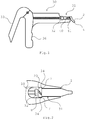
- An inventive system comprises according to the FIGS. 1 and 3 a composite capsule 1, a dispensing gun 30 and a supply syringe 50.
- the composite capsule 1 is connected to the dispensing gun 30.
- the dispensing gun 30 comprises a mechanism 33, by means of which a plunger 32 is pressed in the direction of a capsule receptacle 31 arranged at the front end of the dispensing gun 30.
- the dispensing gun 30 comprises a handle 36 which extends in the radial direction.
- the front surface of the plunger 32 is circular and has a diameter which is slightly smaller than the inner diameter of a receiving space 5 of the composite capsule 1.
- the plunger 32 and the receiving space 5 of the composite capsule 1 are arranged so that upon actuation of the mechanism 33 of the plunger 32 enters the receiving space 5 and exerts pressure on the piston 40 arranged therein.
- the piston 40 is thereby moved in the direction of the applicator tip 2 of the composite capsule 1 and thereby conveys the dental mass 41 located in the receiving space also in the direction of the dispensing tip 2. If the piston 40 pressed by the plunger 32 sufficiently far in the direction of the applicator tip 2, the Dental mass 41 from the outlet opening 4. It is easy for the dentist to specifically apply dental material in the mouth of a patient in this way.
- the composite capsule 1 comprises according to the FIGS. 4 and 5 a receiving space 5, which is bounded by a wall 6.
- the discharge tip 2 At the front end of the receiving space 5 is the discharge tip 2, which forms an angle of approximately 45 ° with the longitudinal axis of the receiving space 5.
- the receiving opening 9 At the rear end of the receiving space 5, the receiving opening 9 is arranged.
- the receiving space 5 has a front portion 15 in which the wall surface is shaped cylindrically is and a rear portion 16 in which the wall surface widens in the direction of the receiving opening 9.
- the discharge tip 2 comprises a channel 3, which extends from the receiving space 5 to the outlet opening 4 arranged at the front end of the discharge tip 2. According to Fig. 6 There is an overlap between the Ausbringspitze 2 and one of the threaded recesses 14 when the Ausbringspitze 2 is projected in the plane of the support surface.
- a collar 20 projects radially outward.
- the covenant is interrupted by two thread grooves 10, of which in FIG. 5 only one can be seen.
- the second thread groove is offset by 180 ° to the first thread groove in the circumferential direction around the collar around.
- the thread grooves 10 form an acute angle with the longitudinal axis of the composite capsule.
- the collar 20 has a cylindrical outer surface, wherein the cylinder axis along the longitudinal axis of the receiving space 5 is aligned.
- the composite capsule is manufactured as a one-piece injection molded part from a transparent plastic material.
- the plastic material acts as an optical filter that blocks short-wave visible light and UV light and is transparent to long-wavelength visible light.
- the optical filter is designed as an edge filter with a sharp transition between the passband and the stopband. The transition between the passband and the stopband is about 520 nm.
- the composite capsule looks orange to an observer.
- the receiving space 5 has a volume of 0.19 ml.
- the collar furthermore comprises a support surface 7 pointing towards the front end of the composite capsule 1 and a rear surface 8 pointing to the rear.
- the thread groove 10 opens into the rear surface 8 in a threaded recess 13 and in the support surface 7 in a threaded recess 14.
- the composite capsule 1 is delivered to the user without content and only filled by the user with a desired amount of dental material. If the dental material is introduced into the receiving space 5, a piston 40 is inserted through the receiving opening 9, so that the receiving space 5 is completed. If pressure is exerted on the piston 40 with the plunger 32 of the dispensing gun 30, it moves forward and presses the dental material in the direction of the outlet opening 4. If the dental compound 41 is not to be used immediately, the outlet opening 4 can be closed with a cap 11.
- the composite capsule 1 As in Fig. 3 shown connected to a supply syringe 50 containing a supply of dental material.
- the supply syringe 50 has at its front end a cone-shaped tip 52.
- Around the cone-shaped tip 52 extends around a lateral surface 51, on the inside of a sauer alloys thread 53 is formed.
- the cone-shaped tip 52 and the thread 53 are sized to conform to the Luer-Lock standard.
- the section 16 of the receiving space 5 of the composite capsule 1 is adapted to the Luer cone, so it lies flat on the top 52.
- the front end of the tip 52 projects into the section 15 of the receiving space 5.
- connection between the composite capsule 1 and the storage syringe 50 is made by the threaded grooves 10 of the composite capsule 1 are brought into engagement with the thread 53 of the storage syringe 50.
- the cone-shaped tip 52 then protrudes into the receiving space 5 of the composite capsule 1. If pressure is exerted on the piston 54 in the storage syringe 50 located dental mass 54, the dental material 54 passes through the opening of the cone-shaped tip 52 from.
- the composite capsule 1 is filled with a desired amount of dental material 54. After filling the composite capsule 1, this is separated from the supply syringe 50 and the piston 40 is inserted through the receiving opening 9 of the composite capsule 1.
- the composite capsule 1 is subsequently inserted into the capsule receptacle 31 of the dispensing gun 30.
- the capsule receptacle 31 is shown in a top view.
- the delivery tip 4 of the composite capsule 1 which in Fig. 1 pointing down, directed into the plane of the drawing.
- the capsule receptacle 31 comprises an insertion shaft for the composite capsule 1, in which the composite capsule 1 can be inserted from above.
- the lateral surfaces of the capsule holder determine the orientation of the composite capsule 1 and are designed so that the composite capsule 1 snaps into place by means of a snap fit.
- the longitudinal extension of the lateral surfaces is smaller than the distance between the support surface 7 and the front end of the composite capsule 1.
- the capsule receptacle 31 further comprises an end face 34 on which the support surface 7 of the capsule seat 31 inserted composite capsule 1 is applied.
- the end face 34 thus forms a counter surface to the support surface 7. This ensures that the composite capsule 1 is not pressed by the plunger 32 forward.
- the applicator tip 2 of the composite capsule 1 points in the same direction as the handle 36 of the applicator gun 30.
- One of the thread grooves 10 then lies according to Fig. 2 in the region of the capsule receptacle 31, in which the support surface 7 does not bear against the mating surface 34. Where the forces between the support surface 7 and the counter surface 34 are transmitted, the collar 20 is not weakened by a thread furrow.
- the collar 20 of the composite capsule 1 according to the invention thus has a dual function in that it is supported on the one hand on the mating surface 34 of the dispensing gun 30 and on the other hand enables the threaded connection with the thread 53.
- the receiving space 5 of the composite capsule 1 is designed so that it rests flat on the cone tip 52 of the storage syringe 50.
Landscapes
- Health & Medical Sciences (AREA)
- Oral & Maxillofacial Surgery (AREA)
- Dentistry (AREA)
- Epidemiology (AREA)
- Life Sciences & Earth Sciences (AREA)
- Animal Behavior & Ethology (AREA)
- General Health & Medical Sciences (AREA)
- Public Health (AREA)
- Veterinary Medicine (AREA)
- Dental Tools And Instruments Or Auxiliary Dental Instruments (AREA)
Claims (10)
- Système constitué d'une seringue d'alimentation (50), d'un pistolet de distribution (33) et d'une capsule à composite (1) pour recevoir et distribuer une pâte dentaire (41), la capsule à composite (1) présentant un espace de réception (5) entouré par une paroi de capsule (6) et s'étendant entre une ouverture de sortie (4) et une ouverture de réception (9), l'ouverture de sortie étant disposée à une extrémité avant de l'espace de réception (5) et l'ouverture de réception (9) étant disposée à une extrémité arrière de l'espace de réception (5), et comportant une surface d'appui (7) qui est fait saillie vers l'extérieur par rapport à la paroi de capsule (6) et qui est orientée en direction de l'extrémité avant et qui forme la surface avant d'une collerette (20) qui s'étend autour du pourtour de la capsule à composite (1) et qui présente une extension en direction longitudinale de la capsule à composite (1),
caractérisé en ce que
la surface d'appui (7) est interrompue par un évidement taraudé (14), en ce que
la surface arrière (8) de la collerette (20) est également pourvue d'un évidement taraudé (13), et en ce que
les évidements taraudés (14, 13) dans la surface avant et dans la surface arrière (8) sont reliés l'un à l'autre par une rainure taraudée (10), en ce que la seringue d'alimentation (50) présente un filetage (53) complémentaire à l'évidement taraudé (14) de la capsule à composite (1), le filetage complémentaire (53) étant agencé autour d'un canal de sortie de la seringue d'alimentation (50), et en ce que
le pistolet de distribution (33) comprend un logement de capsule (31) pour la capsule à composite (1), qui présente une surface complémentaire (34) coopérant avec la surface d'appui (7) de la capsule à composite (1), la surface complémentaire (34) présentant un évidement permettant d'insérer la capsule à composite (1) en direction radiale, et dans l'état inséré dans le logement de capsule (31) la capsule à composite (1) est orientée de telle sorte que la rainure taraudée (10) de la capsule à composite (1) est agencée au niveau de l'évidement de la surface complémentaire (34). - Système selon la revendication 1,
caractérisé en ce que
l'évidement taraudé (13) de la surface arrière est agencé de façon décalée en direction périphérique par rapport à l'évidement taraudé (14) de la surface d'appui (7). - Système selon l'une des revendications 1 à 2,
caractérisé en ce que
la surface d'appui (7) de la capsule à composite (1) présente deux évidements taraudés (14), et en ce que
les évidements taraudés (14) sont agencés en décalage de 180°. - Système selon l'une des revendications 1 à 3,
caractérisé par
un piston (40) conçu pour être introduit dans l'espace de réception (15) de la capsule à composite (1) à travers l'ouverture de réception (9). - Système selon l'une des revendications 1 à 4,
caractérisé en ce que
l'espace de réception (5) de la capsule à composite (1) est de forme cylindrique dans une portion avant (15) et va en s'évasant en direction de l'ouverture de réception (9) dans une portion arrière (16). - Système selon l'une des revendications 1 à 5,
caractérisé en ce que
une pointe de distribution (2) de la capsule à composite (1) est inclinée par rapport à l'axe longitudinal de la capsule à composite (1). - Système selon la revendication 6,
caractérisé en ce que
il existe un chevauchement entre une projection de la pointe de distribution (2) dans le plan de la surface d'appui (7) et une projection de la rainure taraudée (10) dans le plan de la surface d'appui (7). - Système selon la revendication 6 ou 7,
caractérisé en ce que
il est prévu un capuchon adapté à la pointe de distribution (2). - Système selon l'une des revendications 5 à 8,
caractérisé en ce que
la seringue d'alimentation (50) présente une pointe (52) qui va en se rétrécissant, et en ce que
la pointe (52) en rétrécissement est adaptée à la portion (16) de l'espace de réception (5), qui va en s'évasant. - Procédé de distribution d'une pâte dentaire (41) par utilisation d'un système selon l'une des revendications précédentes 1 à 9, comprenant les étapes suivantes consistant à :a. raccorder la capsule à composite (1) à la seringue d'alimentation formant un réservoir (50), la capsule à composite (1) étant reliée au réservoir (50) via une liaison à pas de vis (10, 53) comprenant la rainure taraudée (10) et le filetage complémentaire (53) ;b. distribuer la pâte dentaire (41) hors du réservoir (50) de manière à la transférer jusque dans l'espace de réception (5) de la capsule à composite (1) ;c. refermer l'espace de réception (5) par un piston (40) ;d. insérer la capsule à composite (1) dans le logement de capsule (31) du pistolet de distribution (30), l'insertion s'effectuant en direction radiale à travers l'évidement disposé dans la surface complémentaire (34), de telle sorte que la rainure taraudée (10) de la capsule à composite (1) est agencée au niveau de l'évidement de la surface complémentaire (34) ;e. actionner le pistolet de distribution (30) pour exercer une pression sur le piston (40), de telle sorte que de la pâte dentaire (41) sort hors de la capsule à composite (1).
Applications Claiming Priority (1)
| Application Number | Priority Date | Filing Date | Title |
|---|---|---|---|
| DE201310201460 DE102013201460A1 (de) | 2013-01-30 | 2013-01-30 | Composite-Kapsel und Verfahren zum Ausbringen einer Dentalmasse |
Publications (3)
| Publication Number | Publication Date |
|---|---|
| EP2762103A2 EP2762103A2 (fr) | 2014-08-06 |
| EP2762103A3 EP2762103A3 (fr) | 2015-06-10 |
| EP2762103B1 true EP2762103B1 (fr) | 2018-11-21 |
Family
ID=49943187
Family Applications (1)
| Application Number | Title | Priority Date | Filing Date |
|---|---|---|---|
| EP14150566.9A Not-in-force EP2762103B1 (fr) | 2013-01-30 | 2014-01-09 | Système et procédé de distribution d'une masse dentaire |
Country Status (3)
| Country | Link |
|---|---|
| US (1) | US20140212836A1 (fr) |
| EP (1) | EP2762103B1 (fr) |
| DE (1) | DE102013201460A1 (fr) |
Families Citing this family (3)
| Publication number | Priority date | Publication date | Assignee | Title |
|---|---|---|---|---|
| CN103079493B (zh) * | 2010-05-28 | 2016-08-03 | 可乐丽则武齿科株式会社 | 筒式分配器 |
| WO2019092562A1 (fr) | 2017-11-09 | 2019-05-16 | 3M Innovative Properties Company | Distributeur doté d'une pointe d'applicateur |
| DE102018118577A1 (de) * | 2018-07-31 | 2020-02-06 | Voco Gmbh | Vorrichtung zur Aufnahme und Applikation von Dentalmaterial und Verfahren |
Family Cites Families (14)
| Publication number | Priority date | Publication date | Assignee | Title |
|---|---|---|---|---|
| US3188057A (en) * | 1962-03-12 | 1965-06-08 | Pyles Ind Inc | Apparatus for mixing and dispensing multi-component materials |
| US4198756A (en) * | 1977-11-18 | 1980-04-22 | Dragan William B | Manual extruder |
| GB8506010D0 (en) * | 1985-03-08 | 1985-04-11 | Ici Plc | Extrusion apparatus |
| US5122057A (en) * | 1991-01-07 | 1992-06-16 | Centrix, Inc. | Dosing dental cartridge |
| US5269684A (en) * | 1992-08-31 | 1993-12-14 | Ultradent Products, Inc. | Adjustable brush delivery tip with secondary flow path |
| US5286257A (en) * | 1992-11-18 | 1994-02-15 | Ultradent Products, Inc. | Syringe apparatus with detachable mixing and delivery tip |
| US5692642A (en) * | 1995-10-05 | 1997-12-02 | Brattesani; Steven J. | Fluid dispenser adapter and method of use |
| US5816804A (en) * | 1996-01-19 | 1998-10-06 | Ultradent Products, Inc. | Fiber-ended open orifice delivery tip |
| US6135771A (en) * | 1997-12-02 | 2000-10-24 | Centrix, Inc. | Dental cartridge having an attachable delivery portion |
| US6503084B2 (en) * | 2000-02-24 | 2003-01-07 | Dentsply Detrey G.M.B.H. | Method for dispensing dental materials |
| US6343929B1 (en) * | 2001-01-22 | 2002-02-05 | Ultradent Products, Inc. | Endodontic irrigator tips having fiber covered cannulas and related methods |
| US20040122377A1 (en) * | 2002-12-19 | 2004-06-24 | Fischer Dan E. | Syringe delivery tip adapted to provide controlled flow rate |
| EP1810638B1 (fr) * | 2006-01-24 | 2009-06-17 | 3M Espe AG | Piston pour capsule, méthode pour fabriquer cedit piston, et capsule associée |
| US8753613B2 (en) * | 2007-03-30 | 2014-06-17 | Centrix, Inc. | Dental retraction material having enhanced fluid absorption |
-
2013
- 2013-01-30 DE DE201310201460 patent/DE102013201460A1/de not_active Withdrawn
-
2014
- 2014-01-09 EP EP14150566.9A patent/EP2762103B1/fr not_active Not-in-force
- 2014-01-30 US US14/168,162 patent/US20140212836A1/en not_active Abandoned
Non-Patent Citations (1)
| Title |
|---|
| None * |
Also Published As
| Publication number | Publication date |
|---|---|
| US20140212836A1 (en) | 2014-07-31 |
| EP2762103A2 (fr) | 2014-08-06 |
| EP2762103A3 (fr) | 2015-06-10 |
| DE102013201460A1 (de) | 2014-07-31 |
Similar Documents
| Publication | Publication Date | Title |
|---|---|---|
| EP0157121B1 (fr) | Récipient pour distribuer des pâtes dentaires | |
| EP0378806B1 (fr) | Dispositif de mélange et de distribution de produits pâteux | |
| EP2723482B1 (fr) | Dispositif destiné à mélanger et appliquer un produit ayant peu de bulles | |
| EP0220551B1 (fr) | Seringue pour l'application de masses dentaires et son procédé de fabrication | |
| EP2050477B1 (fr) | Unité d'ampoule dotée d'un adaptateur | |
| EP2085147B1 (fr) | Dispositif doté d'un piston sur lequel est appliquée une pression, destiné à vider une seringue multiple ou une cartouche multiple | |
| CH658995A5 (de) | Zahnaerztliches allzweckabgabesystem. | |
| EP1637233A2 (fr) | Dispositif pour délivrer, notamment pour pulvériser un fluide | |
| EP3022603B1 (fr) | Appareil doseur servant à distribuer manuellement un matériau photodurcissant | |
| DE4419235A1 (de) | Injektionsspritze mit einem Medikamentaufnahmebehälter sowie mit einem Medikamentbehälter | |
| EP2762103B1 (fr) | Système et procédé de distribution d'une masse dentaire | |
| EP3793748A1 (fr) | Applicateur | |
| EP2696794B1 (fr) | Récipient débiteur pour un matériau dentaire | |
| DE102005043805A1 (de) | Zentrierhilfe zum Aufsetzen einer Nadel auf ein Injektionsgerät | |
| EP3528728A1 (fr) | Dispositif de distribution modulaire avec élément de séparation | |
| EP1797920B1 (fr) | Dispositif apte à recevoir et à délivrer une substance fluide | |
| EP2158136B1 (fr) | Dispositif de déversement d'une substance apte à l'écoulement | |
| EP0103746A2 (fr) | Dispositif dispensateur en forme de bâton | |
| DE1966623A1 (de) | Zur einmaligen benutzung bestimmte vorrichtung fuer die aufnahme und ausgabe einer dosis von verunreinigungsempfindlichen behandlungsfluessigkeiten | |
| DE10255134A1 (de) | Abziehvorrichtung für Injektionsnadeln | |
| EP3328470B1 (fr) | Seringue | |
| DE102017101894A1 (de) | Vorrichtung zum Austragen eines fließfähigen Stoffes | |
| EP3484417A1 (fr) | Système mélangeur et distributeur pour substitut osseux | |
| DE102015214697A1 (de) | Composite-Kapsel und Verfahren zum Herstellen einer Composite-Kapsel | |
| DE102023119907A1 (de) | Adapter zum Umfüllen von Mehrkammerkartuschen |
Legal Events
| Date | Code | Title | Description |
|---|---|---|---|
| PUAI | Public reference made under article 153(3) epc to a published international application that has entered the european phase |
Free format text: ORIGINAL CODE: 0009012 |
|
| 17P | Request for examination filed |
Effective date: 20140109 |
|
| AK | Designated contracting states |
Kind code of ref document: A2 Designated state(s): AL AT BE BG CH CY CZ DE DK EE ES FI FR GB GR HR HU IE IS IT LI LT LU LV MC MK MT NL NO PL PT RO RS SE SI SK SM TR |
|
| AX | Request for extension of the european patent |
Extension state: BA ME |
|
| PUAL | Search report despatched |
Free format text: ORIGINAL CODE: 0009013 |
|
| AK | Designated contracting states |
Kind code of ref document: A3 Designated state(s): AL AT BE BG CH CY CZ DE DK EE ES FI FR GB GR HR HU IE IS IT LI LT LU LV MC MK MT NL NO PL PT RO RS SE SI SK SM TR |
|
| AX | Request for extension of the european patent |
Extension state: BA ME |
|
| RIC1 | Information provided on ipc code assigned before grant |
Ipc: A61C 5/06 20060101AFI20150504BHEP |
|
| R17P | Request for examination filed (corrected) |
Effective date: 20151210 |
|
| RBV | Designated contracting states (corrected) |
Designated state(s): AL AT BE BG CH CY CZ DE DK EE ES FI FR GB GR HR HU IE IS IT LI LT LU LV MC MK MT NL NO PL PT RO RS SE SI SK SM TR |
|
| STAA | Information on the status of an ep patent application or granted ep patent |
Free format text: STATUS: EXAMINATION IS IN PROGRESS |
|
| 17Q | First examination report despatched |
Effective date: 20170306 |
|
| REG | Reference to a national code |
Ref country code: DE Ref legal event code: R079 Ref document number: 502014010112 Country of ref document: DE Free format text: PREVIOUS MAIN CLASS: A61C0005060000 Ipc: A61C0005620000 |
|
| GRAP | Despatch of communication of intention to grant a patent |
Free format text: ORIGINAL CODE: EPIDOSNIGR1 |
|
| STAA | Information on the status of an ep patent application or granted ep patent |
Free format text: STATUS: GRANT OF PATENT IS INTENDED |
|
| RIC1 | Information provided on ipc code assigned before grant |
Ipc: A61C 5/66 20170101ALI20180528BHEP Ipc: A61C 5/62 20170101AFI20180528BHEP |
|
| INTG | Intention to grant announced |
Effective date: 20180627 |
|
| GRAS | Grant fee paid |
Free format text: ORIGINAL CODE: EPIDOSNIGR3 |
|
| GRAA | (expected) grant |
Free format text: ORIGINAL CODE: 0009210 |
|
| STAA | Information on the status of an ep patent application or granted ep patent |
Free format text: STATUS: THE PATENT HAS BEEN GRANTED |
|
| AK | Designated contracting states |
Kind code of ref document: B1 Designated state(s): AL AT BE BG CH CY CZ DE DK EE ES FI FR GB GR HR HU IE IS IT LI LT LU LV MC MK MT NL NO PL PT RO RS SE SI SK SM TR |
|
| REG | Reference to a national code |
Ref country code: CH Ref legal event code: EP |
|
| REG | Reference to a national code |
Ref country code: IE Ref legal event code: FG4D Free format text: LANGUAGE OF EP DOCUMENT: GERMAN |
|
| REG | Reference to a national code |
Ref country code: DE Ref legal event code: R096 Ref document number: 502014010112 Country of ref document: DE |
|
| REG | Reference to a national code |
Ref country code: AT Ref legal event code: REF Ref document number: 1066631 Country of ref document: AT Kind code of ref document: T Effective date: 20181215 |
|
| REG | Reference to a national code |
Ref country code: NL Ref legal event code: MP Effective date: 20181121 |
|
| PG25 | Lapsed in a contracting state [announced via postgrant information from national office to epo] |
Ref country code: FI Free format text: LAPSE BECAUSE OF FAILURE TO SUBMIT A TRANSLATION OF THE DESCRIPTION OR TO PAY THE FEE WITHIN THE PRESCRIBED TIME-LIMIT Effective date: 20181121 Ref country code: LV Free format text: LAPSE BECAUSE OF FAILURE TO SUBMIT A TRANSLATION OF THE DESCRIPTION OR TO PAY THE FEE WITHIN THE PRESCRIBED TIME-LIMIT Effective date: 20181121 Ref country code: HR Free format text: LAPSE BECAUSE OF FAILURE TO SUBMIT A TRANSLATION OF THE DESCRIPTION OR TO PAY THE FEE WITHIN THE PRESCRIBED TIME-LIMIT Effective date: 20181121 Ref country code: LT Free format text: LAPSE BECAUSE OF FAILURE TO SUBMIT A TRANSLATION OF THE DESCRIPTION OR TO PAY THE FEE WITHIN THE PRESCRIBED TIME-LIMIT Effective date: 20181121 Ref country code: BG Free format text: LAPSE BECAUSE OF FAILURE TO SUBMIT A TRANSLATION OF THE DESCRIPTION OR TO PAY THE FEE WITHIN THE PRESCRIBED TIME-LIMIT Effective date: 20190221 Ref country code: ES Free format text: LAPSE BECAUSE OF FAILURE TO SUBMIT A TRANSLATION OF THE DESCRIPTION OR TO PAY THE FEE WITHIN THE PRESCRIBED TIME-LIMIT Effective date: 20181121 Ref country code: IS Free format text: LAPSE BECAUSE OF FAILURE TO SUBMIT A TRANSLATION OF THE DESCRIPTION OR TO PAY THE FEE WITHIN THE PRESCRIBED TIME-LIMIT Effective date: 20190321 Ref country code: NO Free format text: LAPSE BECAUSE OF FAILURE TO SUBMIT A TRANSLATION OF THE DESCRIPTION OR TO PAY THE FEE WITHIN THE PRESCRIBED TIME-LIMIT Effective date: 20190221 |
|
| PG25 | Lapsed in a contracting state [announced via postgrant information from national office to epo] |
Ref country code: AL Free format text: LAPSE BECAUSE OF FAILURE TO SUBMIT A TRANSLATION OF THE DESCRIPTION OR TO PAY THE FEE WITHIN THE PRESCRIBED TIME-LIMIT Effective date: 20181121 Ref country code: NL Free format text: LAPSE BECAUSE OF FAILURE TO SUBMIT A TRANSLATION OF THE DESCRIPTION OR TO PAY THE FEE WITHIN THE PRESCRIBED TIME-LIMIT Effective date: 20181121 Ref country code: PT Free format text: LAPSE BECAUSE OF FAILURE TO SUBMIT A TRANSLATION OF THE DESCRIPTION OR TO PAY THE FEE WITHIN THE PRESCRIBED TIME-LIMIT Effective date: 20190321 Ref country code: GR Free format text: LAPSE BECAUSE OF FAILURE TO SUBMIT A TRANSLATION OF THE DESCRIPTION OR TO PAY THE FEE WITHIN THE PRESCRIBED TIME-LIMIT Effective date: 20190222 Ref country code: RS Free format text: LAPSE BECAUSE OF FAILURE TO SUBMIT A TRANSLATION OF THE DESCRIPTION OR TO PAY THE FEE WITHIN THE PRESCRIBED TIME-LIMIT Effective date: 20181121 Ref country code: SE Free format text: LAPSE BECAUSE OF FAILURE TO SUBMIT A TRANSLATION OF THE DESCRIPTION OR TO PAY THE FEE WITHIN THE PRESCRIBED TIME-LIMIT Effective date: 20181121 |
|
| PG25 | Lapsed in a contracting state [announced via postgrant information from national office to epo] |
Ref country code: CZ Free format text: LAPSE BECAUSE OF FAILURE TO SUBMIT A TRANSLATION OF THE DESCRIPTION OR TO PAY THE FEE WITHIN THE PRESCRIBED TIME-LIMIT Effective date: 20181121 Ref country code: IT Free format text: LAPSE BECAUSE OF FAILURE TO SUBMIT A TRANSLATION OF THE DESCRIPTION OR TO PAY THE FEE WITHIN THE PRESCRIBED TIME-LIMIT Effective date: 20181121 Ref country code: PL Free format text: LAPSE BECAUSE OF FAILURE TO SUBMIT A TRANSLATION OF THE DESCRIPTION OR TO PAY THE FEE WITHIN THE PRESCRIBED TIME-LIMIT Effective date: 20181121 Ref country code: DK Free format text: LAPSE BECAUSE OF FAILURE TO SUBMIT A TRANSLATION OF THE DESCRIPTION OR TO PAY THE FEE WITHIN THE PRESCRIBED TIME-LIMIT Effective date: 20181121 |
|
| REG | Reference to a national code |
Ref country code: DE Ref legal event code: R097 Ref document number: 502014010112 Country of ref document: DE |
|
| PG25 | Lapsed in a contracting state [announced via postgrant information from national office to epo] |
Ref country code: SM Free format text: LAPSE BECAUSE OF FAILURE TO SUBMIT A TRANSLATION OF THE DESCRIPTION OR TO PAY THE FEE WITHIN THE PRESCRIBED TIME-LIMIT Effective date: 20181121 Ref country code: EE Free format text: LAPSE BECAUSE OF FAILURE TO SUBMIT A TRANSLATION OF THE DESCRIPTION OR TO PAY THE FEE WITHIN THE PRESCRIBED TIME-LIMIT Effective date: 20181121 Ref country code: MC Free format text: LAPSE BECAUSE OF FAILURE TO SUBMIT A TRANSLATION OF THE DESCRIPTION OR TO PAY THE FEE WITHIN THE PRESCRIBED TIME-LIMIT Effective date: 20181121 Ref country code: SK Free format text: LAPSE BECAUSE OF FAILURE TO SUBMIT A TRANSLATION OF THE DESCRIPTION OR TO PAY THE FEE WITHIN THE PRESCRIBED TIME-LIMIT Effective date: 20181121 Ref country code: RO Free format text: LAPSE BECAUSE OF FAILURE TO SUBMIT A TRANSLATION OF THE DESCRIPTION OR TO PAY THE FEE WITHIN THE PRESCRIBED TIME-LIMIT Effective date: 20181121 |
|
| REG | Reference to a national code |
Ref country code: CH Ref legal event code: PL |
|
| PLBE | No opposition filed within time limit |
Free format text: ORIGINAL CODE: 0009261 |
|
| STAA | Information on the status of an ep patent application or granted ep patent |
Free format text: STATUS: NO OPPOSITION FILED WITHIN TIME LIMIT |
|
| PG25 | Lapsed in a contracting state [announced via postgrant information from national office to epo] |
Ref country code: LU Free format text: LAPSE BECAUSE OF NON-PAYMENT OF DUE FEES Effective date: 20190109 |
|
| REG | Reference to a national code |
Ref country code: BE Ref legal event code: MM Effective date: 20190131 |
|
| GBPC | Gb: european patent ceased through non-payment of renewal fee |
Effective date: 20190221 |
|
| 26N | No opposition filed |
Effective date: 20190822 |
|
| REG | Reference to a national code |
Ref country code: IE Ref legal event code: MM4A |
|
| PG25 | Lapsed in a contracting state [announced via postgrant information from national office to epo] |
Ref country code: SI Free format text: LAPSE BECAUSE OF FAILURE TO SUBMIT A TRANSLATION OF THE DESCRIPTION OR TO PAY THE FEE WITHIN THE PRESCRIBED TIME-LIMIT Effective date: 20181121 |
|
| PG25 | Lapsed in a contracting state [announced via postgrant information from national office to epo] |
Ref country code: BE Free format text: LAPSE BECAUSE OF NON-PAYMENT OF DUE FEES Effective date: 20190131 |
|
| PG25 | Lapsed in a contracting state [announced via postgrant information from national office to epo] |
Ref country code: CH Free format text: LAPSE BECAUSE OF NON-PAYMENT OF DUE FEES Effective date: 20190131 Ref country code: LI Free format text: LAPSE BECAUSE OF NON-PAYMENT OF DUE FEES Effective date: 20190131 |
|
| PG25 | Lapsed in a contracting state [announced via postgrant information from national office to epo] |
Ref country code: GB Free format text: LAPSE BECAUSE OF NON-PAYMENT OF DUE FEES Effective date: 20190221 Ref country code: IE Free format text: LAPSE BECAUSE OF NON-PAYMENT OF DUE FEES Effective date: 20190109 |
|
| REG | Reference to a national code |
Ref country code: AT Ref legal event code: MM01 Ref document number: 1066631 Country of ref document: AT Kind code of ref document: T Effective date: 20190109 |
|
| PG25 | Lapsed in a contracting state [announced via postgrant information from national office to epo] |
Ref country code: TR Free format text: LAPSE BECAUSE OF FAILURE TO SUBMIT A TRANSLATION OF THE DESCRIPTION OR TO PAY THE FEE WITHIN THE PRESCRIBED TIME-LIMIT Effective date: 20181121 |
|
| PG25 | Lapsed in a contracting state [announced via postgrant information from national office to epo] |
Ref country code: AT Free format text: LAPSE BECAUSE OF NON-PAYMENT OF DUE FEES Effective date: 20190109 |
|
| PG25 | Lapsed in a contracting state [announced via postgrant information from national office to epo] |
Ref country code: MT Free format text: LAPSE BECAUSE OF FAILURE TO SUBMIT A TRANSLATION OF THE DESCRIPTION OR TO PAY THE FEE WITHIN THE PRESCRIBED TIME-LIMIT Effective date: 20181121 |
|
| PGFP | Annual fee paid to national office [announced via postgrant information from national office to epo] |
Ref country code: FR Payment date: 20200121 Year of fee payment: 7 |
|
| PG25 | Lapsed in a contracting state [announced via postgrant information from national office to epo] |
Ref country code: CY Free format text: LAPSE BECAUSE OF FAILURE TO SUBMIT A TRANSLATION OF THE DESCRIPTION OR TO PAY THE FEE WITHIN THE PRESCRIBED TIME-LIMIT Effective date: 20181121 |
|
| PGFP | Annual fee paid to national office [announced via postgrant information from national office to epo] |
Ref country code: DE Payment date: 20210120 Year of fee payment: 8 |
|
| PG25 | Lapsed in a contracting state [announced via postgrant information from national office to epo] |
Ref country code: HU Free format text: LAPSE BECAUSE OF FAILURE TO SUBMIT A TRANSLATION OF THE DESCRIPTION OR TO PAY THE FEE WITHIN THE PRESCRIBED TIME-LIMIT; INVALID AB INITIO Effective date: 20140109 |
|
| PG25 | Lapsed in a contracting state [announced via postgrant information from national office to epo] |
Ref country code: FR Free format text: LAPSE BECAUSE OF NON-PAYMENT OF DUE FEES Effective date: 20210131 |
|
| PG25 | Lapsed in a contracting state [announced via postgrant information from national office to epo] |
Ref country code: MK Free format text: LAPSE BECAUSE OF FAILURE TO SUBMIT A TRANSLATION OF THE DESCRIPTION OR TO PAY THE FEE WITHIN THE PRESCRIBED TIME-LIMIT Effective date: 20181121 |
|
| REG | Reference to a national code |
Ref country code: DE Ref legal event code: R119 Ref document number: 502014010112 Country of ref document: DE |
|
| PG25 | Lapsed in a contracting state [announced via postgrant information from national office to epo] |
Ref country code: DE Free format text: LAPSE BECAUSE OF NON-PAYMENT OF DUE FEES Effective date: 20220802 |