EP2763342A2 - Drahtloses Basisstationsgerät das koordinierte HARQ Kommunikation verwendet, ein drahtloses Terminal, drahtloses Kommunikationssystem und ein drachtloses Übertragungsverfahren - Google Patents
Drahtloses Basisstationsgerät das koordinierte HARQ Kommunikation verwendet, ein drahtloses Terminal, drahtloses Kommunikationssystem und ein drachtloses Übertragungsverfahren Download PDFInfo
- Publication number
- EP2763342A2 EP2763342A2 EP20140166571 EP14166571A EP2763342A2 EP 2763342 A2 EP2763342 A2 EP 2763342A2 EP 20140166571 EP20140166571 EP 20140166571 EP 14166571 A EP14166571 A EP 14166571A EP 2763342 A2 EP2763342 A2 EP 2763342A2
- Authority
- EP
- European Patent Office
- Prior art keywords
- base station
- control channel
- wireless base
- station device
- unit
- Prior art date
- Legal status (The legal status is an assumption and is not a legal conclusion. Google has not performed a legal analysis and makes no representation as to the accuracy of the status listed.)
- Granted
Links
Images






Classifications
-
- H—ELECTRICITY
- H04—ELECTRIC COMMUNICATION TECHNIQUE
- H04W—WIRELESS COMMUNICATION NETWORKS
- H04W72/00—Local resource management
- H04W72/20—Control channels or signalling for resource management
-
- H—ELECTRICITY
- H04—ELECTRIC COMMUNICATION TECHNIQUE
- H04L—TRANSMISSION OF DIGITAL INFORMATION, e.g. TELEGRAPHIC COMMUNICATION
- H04L1/00—Arrangements for detecting or preventing errors in the information received
- H04L1/12—Arrangements for detecting or preventing errors in the information received by using return channel
- H04L1/16—Arrangements for detecting or preventing errors in the information received by using return channel in which the return channel carries supervisory signals, e.g. repetition request signals
- H04L1/18—Automatic repetition systems, e.g. Van Duuren systems
- H04L1/1812—Hybrid protocols; Hybrid automatic repeat request [HARQ]
-
- H—ELECTRICITY
- H04—ELECTRIC COMMUNICATION TECHNIQUE
- H04L—TRANSMISSION OF DIGITAL INFORMATION, e.g. TELEGRAPHIC COMMUNICATION
- H04L1/00—Arrangements for detecting or preventing errors in the information received
- H04L1/12—Arrangements for detecting or preventing errors in the information received by using return channel
- H04L1/16—Arrangements for detecting or preventing errors in the information received by using return channel in which the return channel carries supervisory signals, e.g. repetition request signals
- H04L1/18—Automatic repetition systems, e.g. Van Duuren systems
-
- H—ELECTRICITY
- H04—ELECTRIC COMMUNICATION TECHNIQUE
- H04L—TRANSMISSION OF DIGITAL INFORMATION, e.g. TELEGRAPHIC COMMUNICATION
- H04L1/00—Arrangements for detecting or preventing errors in the information received
- H04L1/12—Arrangements for detecting or preventing errors in the information received by using return channel
- H04L1/16—Arrangements for detecting or preventing errors in the information received by using return channel in which the return channel carries supervisory signals, e.g. repetition request signals
- H04L1/18—Automatic repetition systems, e.g. Van Duuren systems
- H04L1/1829—Arrangements specially adapted for the receiver end
- H04L1/1861—Physical mapping arrangements
-
- H—ELECTRICITY
- H04—ELECTRIC COMMUNICATION TECHNIQUE
- H04L—TRANSMISSION OF DIGITAL INFORMATION, e.g. TELEGRAPHIC COMMUNICATION
- H04L5/00—Arrangements affording multiple use of the transmission path
- H04L5/003—Arrangements for allocating sub-channels of the transmission path
- H04L5/0044—Allocation of payload; Allocation of data channels, e.g. PDSCH or PUSCH
-
- H—ELECTRICITY
- H04—ELECTRIC COMMUNICATION TECHNIQUE
- H04L—TRANSMISSION OF DIGITAL INFORMATION, e.g. TELEGRAPHIC COMMUNICATION
- H04L5/00—Arrangements affording multiple use of the transmission path
- H04L5/003—Arrangements for allocating sub-channels of the transmission path
- H04L5/0053—Allocation of signalling, i.e. of overhead other than pilot signals
-
- H—ELECTRICITY
- H04—ELECTRIC COMMUNICATION TECHNIQUE
- H04W—WIRELESS COMMUNICATION NETWORKS
- H04W72/00—Local resource management
- H04W72/04—Wireless resource allocation
- H04W72/044—Wireless resource allocation based on the type of the allocated resource
-
- H—ELECTRICITY
- H04—ELECTRIC COMMUNICATION TECHNIQUE
- H04W—WIRELESS COMMUNICATION NETWORKS
- H04W92/00—Interfaces specially adapted for wireless communication networks
- H04W92/16—Interfaces between hierarchically similar devices
- H04W92/20—Interfaces between hierarchically similar devices between access points
-
- H—ELECTRICITY
- H04—ELECTRIC COMMUNICATION TECHNIQUE
- H04L—TRANSMISSION OF DIGITAL INFORMATION, e.g. TELEGRAPHIC COMMUNICATION
- H04L1/00—Arrangements for detecting or preventing errors in the information received
- H04L1/0001—Systems modifying transmission characteristics according to link quality, e.g. power backoff
- H04L1/0023—Systems modifying transmission characteristics according to link quality, e.g. power backoff characterised by the signalling
- H04L1/0025—Transmission of mode-switching indication
-
- H—ELECTRICITY
- H04—ELECTRIC COMMUNICATION TECHNIQUE
- H04L—TRANSMISSION OF DIGITAL INFORMATION, e.g. TELEGRAPHIC COMMUNICATION
- H04L1/00—Arrangements for detecting or preventing errors in the information received
- H04L1/12—Arrangements for detecting or preventing errors in the information received by using return channel
- H04L1/16—Arrangements for detecting or preventing errors in the information received by using return channel in which the return channel carries supervisory signals, e.g. repetition request signals
- H04L1/18—Automatic repetition systems, e.g. Van Duuren systems
- H04L1/1867—Arrangements specially adapted for the transmitter end
- H04L1/1887—Scheduling and prioritising arrangements
-
- H—ELECTRICITY
- H04—ELECTRIC COMMUNICATION TECHNIQUE
- H04L—TRANSMISSION OF DIGITAL INFORMATION, e.g. TELEGRAPHIC COMMUNICATION
- H04L1/00—Arrangements for detecting or preventing errors in the information received
- H04L1/12—Arrangements for detecting or preventing errors in the information received by using return channel
- H04L1/16—Arrangements for detecting or preventing errors in the information received by using return channel in which the return channel carries supervisory signals, e.g. repetition request signals
- H04L1/18—Automatic repetition systems, e.g. Van Duuren systems
- H04L1/1867—Arrangements specially adapted for the transmitter end
- H04L1/1896—ARQ related signaling
-
- H—ELECTRICITY
- H04—ELECTRIC COMMUNICATION TECHNIQUE
- H04L—TRANSMISSION OF DIGITAL INFORMATION, e.g. TELEGRAPHIC COMMUNICATION
- H04L1/00—Arrangements for detecting or preventing errors in the information received
- H04L2001/0092—Error control systems characterised by the topology of the transmission link
- H04L2001/0097—Relays
-
- H—ELECTRICITY
- H04—ELECTRIC COMMUNICATION TECHNIQUE
- H04W—WIRELESS COMMUNICATION NETWORKS
- H04W36/00—Hand-off or reselection arrangements
- H04W36/02—Buffering or recovering information during reselection ; Modification of the traffic flow during hand-off
- H04W36/023—Buffering or recovering information during reselection
-
- H—ELECTRICITY
- H04—ELECTRIC COMMUNICATION TECHNIQUE
- H04W—WIRELESS COMMUNICATION NETWORKS
- H04W36/00—Hand-off or reselection arrangements
- H04W36/16—Performing reselection for specific purposes
- H04W36/18—Performing reselection for specific purposes for allowing seamless reselection, e.g. soft reselection
Definitions
- Packet communication technology includes, for example, E-UTRA (Evolved Universal Terrestrial Radio Access) communication technology which has been studies as a next generation mobile telephone communication standard.
- E-UTRA Evolved Universal Terrestrial Radio Access
- a coordinated transmission system using a distributed antenna arranged in a different base station is proposed in relation to the multi-input and multi-output (MIMO) technology corresponding to macroscopic fading.
- MIMO multi-input and multi-output
- the systems described in the following non-patent documents 2 through 6 are proposed. These systems aim at attaining both a macroscopic diversity effect and a MIMO effect.
- the LTE advanced standard as a next generation standard of the LTE has been developed as the fourth generation system (4G).
- 4G fourth generation system
- DL downlink
- UL uplink
- a practical discussion of the problem above has been disclosed in, for example, the following non-patent document 8.
- the packet communication technology is required to enable the high-speed communications at a mobile terminal.
- a reception device receives communication information while detecting an error based on the error correction code added to a communication packet by transmission device. Then, the reception device returns to the transmission device an ACK (acknowledgement) or a NAK (negative acknowledgement) about the reception status of the communication packet. The transmission device retransmits transmission information when the reception device returns a NAK or when no transmission status confirmation can be received before a certain period has passed after a packet is transmitted.
- the retransmission pattern is determined on the transmission device side after considering that the data whose decoding has failed by the reception device is not discarded but decoded by a combination with retransmission data in the process of a layer 1 protocol hierarchical level of the LTE etc.
- the data whose reception has failed is not discarded, but decoded by a combination with retransmission data.
- retransmission control is realized with high efficiency and high accuracy.
- Patent Document 1 In the prior art disclosed as Patent Document 1 or non-patent documents 1 through 10, no practical technology for realizing the HARQ in the coordinated transmission has not been disclosed.
- Patent Document 2 refers to a practical system for realizing the HARQ in the packet transmission using a MIMO multiple transmission antenna.
- the MIMO is based on that a plurality of antennas are accommodated in one base station while the coordinated transmission is based on that the antennas of a plurality of base stations arranged in a distributed manner perform a coordinated transmission in the downlink direction toward a mobile terminal.
- a coordinated transmission including a HARQ between the base stations arranged in the distributed manner it is necessary to solve the problems, which is not necessary in the MIMO, of the communication system for user data and channel data, timing, etc. among the base stations.
- the combination of a new data packet and a retransmission data packet in the HARQ with the coordinated transmission is not disclosed by the above-mentioned prior art, which remains as an unsolved problem.
- the problem of the present invention is to realize an appropriate and efficient HARQ process in the coordinated transmission system.
- the aspect described below is based on the wireless communication system in which the first wireless base station device and the second wireless base station device perform a coordinated transmission process to allow the wireless terminal device not to discard a packet on which decoding has failed but to combine the packet with a retransmitted packet and decode the resultant packet while controlling the retransmission of a packet according to the transmission status information returned from the wireless terminal device, the wireless base station device or the wireless terminal device which belong to the wireless communication system, or the wireless communication method for realizing the process.
- a first packet transmission unit transmits as a first packet a new data packet or a retransmission data packet corresponding to a retransmit request from the first wireless base station device to the wireless terminal device when the retransmit request is issued to the coordinated transmission process by the wireless terminal device.
- a packet transfer unit transfers the information about a second packet different from the first packet between the new data packet and the retransmission data packet from the first wireless base station device to the second wireless base station device.
- the packet transfer unit performs a transfer process using, for example, an X2 interface regulated between the first wireless base station device and the second wireless base station device.
- the second packet transmission unit transmits the second packet according to the information transferred from the packet transfer unit in synchronization with the transmission process of the first packet by the first packet transmission unit from the second wireless base station device to the wireless terminal device when the retransmit request is issued.
- each of the first wireless base station device and the second wireless base station device has a retransmission buffer unit
- the first wireless base station device can be configured to hold the information about the packet on which a coordinated transmission process is performed for the wireless terminal device in the retransmission buffer unit in the first wireless base station device
- the second wireless base station device can be configured not to hold the information about the packet on which the coordinated transmission process is performed for the wireless terminal device in the retransmission buffer unit in the second wireless base station device.
- the first packet can be configured as a retransmission data packet
- the second packet can be configured as a new data packet.
- the packet transfer unit reads the information about the retransmission data packet from the retransmission buffer unit in the first wireless base station device, and transfers the information to the second wireless base station device.
- the packet transfer unit transfers, for example, the communication control information relating to the second wireless base station device for communication between the first wireless base station device and the wireless terminal device and the information relating to the transmission timing of the second packet by the second wireless base station device.
- a control information communication unit for communicating the control information about the communication by the first wireless base station device to the wireless terminal device and the control information about the communication by the second wireless base station device to the wireless terminal device between the first wireless base station device and the wireless terminal device can be further included.
- the control information communication unit can perform the transmission of control information from the first wireless base station device to the wireless terminal device through a physical downlink control channel and perform the transmission of the control information from the wireless terminal device to the first wireless base station device through a physical uplink control channel.
- the physical uplink control channel in this case includes at least, for example, the individual channel quality indication information for each of the first wireless base station device and the second wireless base station device, and the precoding matrix indication information and the rank indication information common to the first wireless base station device and the second wireless base station device.
- the physical downlink control channel includes at least, for example, the individual modulation and coding scheme information and the individual precoding information for each of the first wireless base station device and the second wireless base station device.
- the wireless communication system according to embodiment 6 or 7 has the characteristics above.
- control information from the wireless terminal device to the first wireless base station device can be configured to include the transmission status information (HARQ-ACK/NAK) indicating a reception result of the packet from the first wireless base station device and a reception result of the packet from the second wireless base station device, respectively.
- HARQ-ACK/NAK transmission status information
- the first wireless base station device can be configured to centrally control at least the assignment of a wireless terminal device, the assignment of communication resources, and the control of transmission timing associated with the coordinated transmission process.
- the wireless terminal device for performing the communication by the wireless communication system having the above-mentioned configuration has the following aspects.
- a retransmission data packet reception unit performs a receiving process on a retransmission data packet when a retransmit request is issued.
- a new data packet reception unit When the retransmission data packet reception unit successfully performs the receiving process on the retransmission data packet, a new data packet reception unit performs a successive interference cancellation process on the received signal received by the wireless terminal device through the retransmission data packet on which the receiving process has been successfully performed, and the receiving process of a new data packet according to a resultant received signal is performed.
- a coordinated transmission process determining unit for determining whether or not the coordinated transmission process is to be performed and determining the first wireless base station device and the second wireless base station device for performing the process when the execution of the coordinated transmission process is determined can be further included.
- the coordinated transmission process determining unit makes a determination according to the information about the reception power for the reference signal to be received from each wireless base station device currently in communication.
- FIG. 1 is an explanatory view of a network model based on which the present embodiment is designed.
- a network is configured as a packet communication system including two wireless base stations for coordinatedly performing a service on a wireless mobile terminal (UE: User Equipment) such as a mobile telephone terminal etc.
- UE User Equipment
- a packet communication system can be realized as, for example, an E-UTRA (Evolved Universal Terrestrial Radio Access) system in accordance with the LTE communication standard on which a standardizing operation is performed by 3GPP.
- E-UTRA Evolved Universal Terrestrial Radio Access
- a base station In the LTE etc., a base station is referred to as an eNode-B (evolved Node B). In the present embodiment, in the description below, a base station is referred to as an eNode-B or an eNB for short.
- one of the two wireless base stations is a serving base station (serving eNode-B, hereinafter referred to as a "serving eNB” or a “S-eNB” for short), and the other is referred to as a coordinated base station (coordinated eNode-B, hereinafter referred to as a "coordinated eNB” or a "C-eNB” as necessary).
- the determination as to which the eNB belongs, a serving eNB or a coordinated eNB depends on the long-period power intensity received by each UE. Therefore, the positioning of the eNB for each UE can be different. As a reasonable definition, the long-period power intensity from the serving eNB received by each UE is higher than that of the coordinated eNB.
- FIG. 2 is a configuration of a packet transmission device according to an embodiment configured in the eNode-B on the network illustrated in FIG. 1 .
- FIG. 3 is a configuration of a packet reception device according to an embodiment configured in the UE illustrated in FIG. 1 .
- the transmission device in FIG. 2 is provided on the downlink side of the eNode-B, and the reception device in FIG. 2 is provided on the downlink side of the UE.
- the configuration of the transmission/reception device on the uplink channel side of the devices has a common configuration, and the detailed description is omitted here.
- the transmission device illustrated in FIG. 2 includes a new data packet transmission unit 201, a retransmission data packet transmission unit 202, a channel assignment unit 203, a modulation unit 204, a wireless processing unit 205, a transmission control unit 206, an uplink control channel reception unit 207, and an X2 control channel transmission/reception unit 208.
- the new data packet transmission unit 201 is further configured by a block generation unit 201-1, a new portion acquisition unit 201-2, and a new data packet coding unit 201-3.
- the retransmission data packet transmission unit 202 is further configured by a retransmission buffer unit 202-1, a retransmission portion acquisition unit 202-2, and a retransmission data packet coding unit 202-3.
- the reception device illustrated in FIG. 3 includes a wireless processing unit 301, a retransmission data packet reception unit 302, a new data packet reception unit 303, a reception control unit 304, and an uplink control channel transmission unit 305.
- the retransmission data packet reception unit 302 is further configured by a retransmission data packet demodulation unit 302-1, a retransmission buffer unit 302-2, a retransmission portion combination unit 302-3, a retransmission data packet decoding unit 302-4, and a output distribution unit 302-5.
- the new data packet reception unit 303 is further configured by a retransmission data packet re-coding unit 303-1, a retransmission data packet re-modulation unit 303-2, a canceller unit 303-3, a new data packet demodulation unit 303-4, and a new data packet decoding unit 303-5.
- a very unique and important behavior for the HARQ can be the block error rate of normally 1% or less when a retransmission data packet is decoded after the HARQ combining process performed by the retransmission portion combination unit 305-3 illustrated in FIG. 2 .
- a decoded retransmission data packet is positively used, thereby realizing an effective SIC process. That is, in the embodiment illustrated in FIG. 2 , a retransmission packet is first detected in the UE, and then other packets (new or retransmission packets) are detected.
- one new packet and one retransmission packet are delivered in complete synchronization toward one UE from two coordinatedly operating eNodes-B which implement a transmission device of a downlink system illustrated in FIG. 1 .
- FIG. 4 is an explanatory view of grouping cases in which two eNodes-B coordinatedly operate.
- a coordinated transmission is grouped into four types of scenarios.
- Each scenario refers to a different channel resource assignment, and a different control channel design.
- the explanation here refers to the case of one UE only, but the scenario for a plurality of UEs is described later.
- the new data packet reception unit 303 illustrated in FIG. 3 performs the receiving process while suppressing the interference from each other in the SIC process.
- the two types of transmission packets that is, the retransmission data packet and the new data packet
- a new data packet is delivered from the serving eNB to the UE simultaneously when a retransmission data packet is delivered from the coordinated eNB to the UE.
- the retransmission data packet is transferred from the serving eNB to the coordinated eNB.
- the new data packet reception unit 303 illustrated in FIG. 3 performs the receiving process while suppressing the interference from each other in the SIC process.
- scenario 2 illustrated in FIG. 4(b) and the scenario 3 illustrated in FIG. 4(c) are better transmission systems for providing the highest diversity gain by a macroscopic transmission analysis and a cancellation gain by the SIC process because since the BLER (block error rate) for the retransmission data packet after a HARQ combination is sufficiently low, the retransmission data packet can be first extracted, and then the new data packet can be extracted by the SIC process, thereby acquiring a better result. Therefore, it is preferable that one new data packet and one retransmission data packet can be constantly acquired as a rule of the coordinated transmission, and they can be transmitted simultaneously from both the serving eNB and the coordinated eNB.
- BLER block error rate
- the probability of a retransmission is 8 - 10 %.
- the probability of a retransmission increases up to 70 - 80 %. Therefore, when there are terminal groups coexisting and moving at different speeds, the probability of retransmissions can be estimated as 30 - 40 %. It means the possibility of the coordinated HARQ transmission between the new data packet and the retransmission data packet is 23 - 29 %. It is considered that the probability that the scenario 1 illustrated in FIG. 4(a) as a normal coordinated transmission without a retransmission is approximately 70 %. However, since the scenario 4 illustrated in FIG. 4 (d) indicates a low occurrence probability of a HARQ packet, it does not occur in a practical system. Therefore, the probability that the scenario 4 is adopted is nearly zero.
- FIG. 5 is an explanatory view of the coordinated downlink HARQ transmission system for the scenario 2.
- a new data packet received at the UE for example, a new data packet #0
- the data is retransmitted from the serving eNB simultaneously with the new packet (for example, a new data packet #12) delivered from the coordinated eNB (C-eNB) to the synchronous transmission timing determined by the serving eNB (S-eNB).
- C-eNB coordinated eNB
- S-eNB serving eNB
- FIG. 5(a) is a block diagram of the configuration of the process of the transmission device for the scenario 2.
- a retransmission buffer unit 504 on the serving eNB side in FIG. 5(a) corresponds to the retransmission buffer unit 202-1 illustrated in FIG. 2 .
- a first packet transmission unit 501 on the serving eNB side corresponds to the portion excluding the retransmission buffer unit 202-1 in the retransmission data packet transmission unit 202 illustrated in FIG. 2 .
- an RF 503 on the serving eNB side corresponds to the portion configured by the channel assignment unit 203, the modulation unit 204, and the wireless processing unit 205 illustrated in FIG. 2 .
- the second packet transfer unit 503 on the coordinated eNB side in FIG. 5 (a) corresponds to the new data packet transmission unit 201 in FIG. 2 .
- An RF 505 on the coordinated eNB side corresponds to the portion configured by the channel assignment unit 203, the modulation unit 204, and the wireless processing unit 205 in FIG. 2 .
- a packet transfer unit 502 for transferring a new data packet from the serving eNB to the coordinated eNB corresponds to an X2 control channel transmission/reception unit 108 illustrated in FIG. 2 .
- the first packet transmission unit 501 performs an operation of transmitting a retransmission data packet 507 in the transmission device on the serving eNB side.
- the second packet transfer unit 503 performs the operation of transmitting a new data packet 508 corresponding to the information transferred from the serving eNB by the packet transfer unit 502.
- FIG. 6 is an explanatory view of the coordinated downlink HARQ transmission system for the scenario 3.
- the new data packet for example, a new data packet #0
- the data is transferred through the X2 interface along a corresponding control channel to the coordinated eNB.
- a new packet for example, a new data packet #4
- a similar process is generated with a retransmission packet #5 (or #14) transmitted with a new data packet #9 (or #7).
- FIG. 6(a) is a block diagram of the process configuration of the transmission device for the scenario 3.
- a retransmission buffer unit 604 on the serving eNB side in FIG. 6(a) corresponds to the retransmission buffer unit 202-1 in FIG. 2 .
- a first packet transfer unit 601 on the serving eNB side corresponds to the new data packet transmission unit 201 in FIG. 2 .
- an RF 605 on the serving eNB side corresponds to the portion configured by the channel assignment unit 203, the modulation unit 204, and the wireless processing unit 205.
- the transmission device in FIG. 2 is implemented as a downlink system on the serving eNB side
- a retransmission buffer unit 604 on the serving eNB side in FIG. 6(a) corresponds to the retransmission buffer unit 202-1 in FIG. 2 .
- a first packet transfer unit 601 on the serving eNB side corresponds to the new data packet transmission unit 201 in FIG. 2 .
- the second packet transfer unit 603 on the coordinated eNB side in FIG. 6(a) corresponds to the portion excluding the retransmission buffer unit 202-1 in the retransmission data packet transmission unit 202 in FIG. 2 .
- an RF 605 on the coordinated eNB side corresponds to the portion configured by the channel assignment unit 203, the modulation unit 204, and the wireless processing unit 205 in FIG. 2 .
- a packet transfer unit 602 for transferring a retransmission data packet from the retransmission buffer unit 604 in the serving eNB to the coordinated eNB corresponds to the X2 control channel transmission/reception unit 108 in FIG. 2 .
- the first packet transmission unit 601 performs an operation of transmitting a new data packet 607 in the transmission device on the serving eNB side.
- the second packet transfer unit 603 performs the operation of transmitting a retransmission data packet 608 corresponding to the information transferred from the retransmission buffer unit 604 in the serving eNB by the packet transfer unit 502.
- the scenario 2 is more preferable than the scenario 3 because, according to the scenario 2, the coordinated eNB receives a new block transferred from the serving eNB through the X2 interface, and can deliver a new data packet generated based on the received block without considering whether or not the packet has been correctly received on the UE side as described later in the explanation of the control channel.
- the serving eNB is totally responsible including the control channel access for the receiving process and the HARQ. This simplifies the design of the coordinated eNB.
- the configuration of the scenario 3 can be adopted.
- the block generation unit 201-1 generates a block of a predetermined size from an information bit to be transmitted.
- the size of a block generated by the block generation unit 201-1 is equal to the amount of information bit which can be stored in one packet. That is, a normal packet to be transmitted by a transmission device includes information bits corresponding to one block.
- the retransmission buffer unit 202-1 temporarily holds for a retransmission a block of the information bits generated by the block generation unit 201-1.
- the retransmission buffer unit 202-1 can sequentially discard the block which has been correctly decoded by the reception device and is not to be retransmitted.
- the transmission control unit 206 controls the new portion acquisition unit 201-2 and the retransmission portion acquisition unit 202-2 according to the control signal received by the uplink control channel reception unit 207 from the UE side through a control channel.
- the transmission control unit 206 first instructs the new portion acquisition unit 201-2 to acquire a new block generated by the block generation unit 201-1 and corresponding to the UE to be processed, and output it to the new data packet coding unit 201-3 for a transmission.
- the transmission control unit 206 instructs the retransmission portion acquisition unit 202-2 to stop the operation.
- the transmission control unit 206 instructs the new portion acquisition unit 201-2 to output the new block also to the X2 control channel transmission/reception unit 208, and transfer it also to the coordinated eNB corresponding to the UE to be processed.
- the transmission control unit 206 instructs the new portion acquisition unit 201-2 to acquire a new block received by the X2 control channel transmission/reception unit 208 and transferred from the serving eNB corresponding to the UE to be processed, and output it to the new data packet coding unit 201-3 for a transmission.
- the transmission control unit 206 instructs the retransmission portion acquisition unit 202-2 to acquire a transmitted block (retransmission block) corresponding to the NAK held in the retransmission buffer unit 202, and output it to the retransmission data packet coding unit 202-3 for a retransmission.
- the transmission control unit 206 instructs the new portion acquisition unit 201-2 to acquire a new block generated by the block generation unit 201-1 and corresponding to the UE to be processed, and output it not to the new data packet coding unit 201-3 but to the X2 control channel transmission/reception unit 208 to transfer it to the coordinated eNB corresponding to the UE to be processed.
- the transmission control unit 206 instructs the new portion acquisition unit 201-2 to acquire a new block received by the X2 control channel transmission/reception unit 208 and transferred from the serving eNB corresponding to the UE to be processed, and output it to the new data packet coding unit 201-3 for a transmission.
- the transmission control unit 206 instructs the retransmission portion acquisition unit 202-2 to acquire a transmitted block (retransmission block) corresponding to the NAK held in the retransmission buffer unit 202 to output it not to the retransmission data packet coding unit 202-3 but to the X2 control channel transmission/reception unit 208 and transfer it to the coordinated eNB corresponding to the UE to be processed.
- the transmission control unit 206 instructs the new portion acquisition unit 201-2 to acquire a new block generated by the block generation unit 201-1 and corresponding to the UE to be processed, and output it to the new data packet coding unit 201-3 for a retransmission.
- the transmission control unit 206 instructs the retransmission portion acquisition unit 202-2 to acquire a retransmission block received by the X2 control channel transmission/reception unit 208 and transferred from the serving eNB corresponding to the UE to be processed, and output it to the retransmission data packet coding unit 202-3 for a transmission.
- An ACK and a NAK are control signals stored with user data, transferred from a certain UE to be processed, and received by the uplink control channel reception unit 207 in the transmission device operating as a serving eNB for the certain UE as uplink control information (UCI) described later.
- UCI uplink control information
- These ACK and NAK indicate whether or not a reception error of a packet has occurred in the UE, and is returned from the UE to the corresponding serving eNB for each received packet.
- the new data packet coding unit 303-1 in the new data packet transmission unit 201 when a new block is input from the new portion acquisition unit 201-2, the new data packet coding unit 303-1 in the new data packet transmission unit 201 generates a new packet in which the new block is included in an information bit section and a corresponding parity bit is included in a parity bit section.
- the retransmission data packet coding unit 202-3 in the retransmission data packet transmission unit 202 When a retransmission block is input from the retransmission portion acquisition unit 202-2, the retransmission data packet coding unit 202-3 in the retransmission data packet transmission unit 202 generates a retransmission packet in which the retransmission block is included in an information bit section and a corresponding parity bit is included in a parity bit section.
- the channel assignment unit 203 assigns the new packet generated by the new data packet coding unit 201-3 or the retransmission packet generated by the retransmission data packet coding unit 202-3 to a communication channel corresponding to the UE to be processed, and outputs the resultant frame data to the modulation unit 204.
- the modulation unit 204 modulates the frame data output from the channel assignment unit 203, and outputs the data to the wireless processing unit 205.
- the wireless processing unit 205 performs a predetermined wireless transmitting process on the frame data after the modulation, and transmits the resultant data through an antenna not illustrated in the attached drawings.
- the reception device is provided with the retransmission data packet reception unit 302 and the new data packet reception unit 303.
- the reception control unit 304 can recognize whether a received packet is a new data packet or a retransmission data packet according to the new data indication information (refer to FIG. 9(b) ) included in the downlink control information (DCI) transmitted from the serving eNB with the received packet through a physical downlink control channel as described later.
- the recognition is similar to the identification between the scenario 1 and the scenario 2, or between the scenario 1 and the scenario 3.
- the reception control unit 304 performs the identifying process based on the output of the retransmission data packet demodulation unit 302-1 which constantly performs the demodulating process.
- the retransmission data packet reception unit 302 when the reception device operates according to the scenario 1 ( FIG. 4 (a) ) described above, the retransmission data packet reception unit 302, the retransmission data packet re-coding unit 303-1, the retransmission data packet re-modulation unit 303-2, and the canceller unit 303-3 in the new data packet reception unit 303 do not operate, and the received signal received by the wireless processing unit 301 through an antenna passes through the canceller unit 303-3 in the new data packet reception unit 303 and enters the new data packet demodulation unit 303-4.
- the new data packet demodulation unit 303-4 demodulates the received packet from each communication channel configuring the received signal input from the wireless processing unit 301, and outputs the received packet to the new data packet decoding unit 303-5.
- the new data packet decoding unit 303-5 decodes the input new data packet, and outputs resultant new information bits to the processing unit at the subsequent stage but not illustrated in the attached drawings.
- both retransmission data packet reception unit 302 and new data packet reception unit 303 operate under the control of the reception control unit 304.
- Described first is the operation of the retransmission data packet reception unit 302.
- the retransmission data packet demodulation unit 302-1 demodulates the received packet from each communication channel configuring the received signal input from the wireless processing unit 301, and outputs the received packet to the retransmission portion combination unit 302-3.
- the retransmission data packet demodulation unit 302-1 performs a demodulating process regardless of whether the received packet is a retransmission data packet or a new data packet to enable the identifying process by the reception control unit 304.
- the retransmission portion combination unit 302-3 With the timing of processing on a retransmission packet indicated by the reception control unit 304, the retransmission portion combination unit 302-3 combines the retransmission data packet input from the retransmission data packet demodulation unit 302-1 with the past data packet held in the retransmission buffer unit 302-2 after a first reception failure. Then, the retransmission portion combination unit 302-3 outputs the combination result to the retransmission data packet decoding unit 302-4.
- the reception control unit 304 receives retransmission sequence information and other control information as a part of downlink control information (DCI) transmitted with a received packet from the serving eNB through the physical downlink control channel, and notifies the retransmission portion combination unit 302-3 of these pieces of control information.
- the retransmission portion combination unit 302-3 performs the process of combining retransmission packets in the HARQ system according to the control information.
- DCI downlink control information
- the retransmission data packet decoding unit 302-4 decodes the input retransmission data packet, and outputs the resultant reconstructed information bits to the output distribution unit 302-5.
- the output distribution unit 302-5 When the information bits are successfully reconstructed, the output distribution unit 302-5 outputs them to the processing unit at the subsequent stage but not illustrated in the attached drawings. Simultaneously, the output distribution unit 302-5 outputs the reconstructed information bits to the retransmission data packet re-coding unit 303-1 in the new data packet reception unit 303.
- the retransmission data packet re-coding unit 303-1 and the retransmission data packet re-modulation unit 303-2 are operated, and a replica of a successfully received retransmission data packet is generated.
- the canceller unit 303-3 performs a cancelling process on the interference signal components in the retransmission data packet received from the serving eNB (in the case of the scenario 2) or the coordinated eNB (in the case of the scenario 3) for the received signal input from the wireless processing unit 301 as a successive interference cancellation process.
- the canceller unit 303-3 appropriately extracts only the received signal components of the new data packet received from the coordinated eNB (in the case of the scenario 2) or the serving eNB (in the case of the scenario 3), and outputs the result to the new data packet demodulation unit 303-4.
- the new data packet demodulation unit 303-4 demodulates the received packet from each communication channel configuring the received signal from which the interference components input from the canceller unit 303-3 are removed, and outputs the received packet to the new data packet decoding unit 303-5.
- the new data packet decoding unit 303-5 decodes the input new data packet, and outputs the resultant new information bits to the processing unit at the subsequent stage but not illustrated in the attached drawings.
- the reconstructing process on the retransmission data packet fails in the retransmission data packet reception unit 302, and no input is performed from the output distribution unit 302-5 to the retransmission data packet re-coding unit 303-1, then the input from the retransmission data packet re-modulation unit 303-2 to the canceller unit 303-3 is set to zero.
- the operation of the canceller unit 303-3 becomes invalid equivalently.
- the new data packet demodulation unit 303-4 and the new data packet decoding unit 303-5 extract a new data packet without the cancelling process.
- the reception control unit 304 correctly recognizes the physical downlink control channel from the serving eNode-B described later according to, for example, the reference signal (RS) in the received signal.
- RS reference signal
- the following interactive system capable of improving the system performance can also be applied.
- a retransmission data packet and a new data packet are assigned to the serving eNB and the coordinated eNB (in the case of the scenario 2) or inversely (in the case of the scenario 3) to perform a coordinated transmission, thereby successfully and simultaneously transmitting a retransmission data packet and a new data packet corresponding to the same UE using the same channel resources.
- channels can also be effectively used.
- the assignment of channel resources and the user scheduling for a coordinated transmission are centrally controlled by the transmission control unit 206 ( FIG. 2 ) in the serving eNB.
- a link gap ⁇ ue or, in place of it, a reference signal receiving power (RSRP) difference used as a term in the LTE is used.
- the parameter is defined as a difference of logarithm received signal powers between the serving eNB and the coordinated eNB in the UE. If the link gap ⁇ ue is smaller than the link gap target ⁇ as another parameter, the coordinated transmission is performed. Otherwise, a normal transmission is preferable. Using these parameters, a band width for a coordinated transmission can be easily controlled.
- the reception control unit 304 in the reception device ( FIG. 3 ) of the UE sequentially detects the RSRP deffrence of each received RS during communications, and notifies the serving eNB side of the result through the uplink control channel transmission unit 305.
- the uplink control channel reception unit 207 in the current serving eNB ( FIG. 2 ) receives it, and the transmission control unit 206 ( FIG. 2 ) determines whether or not the coordinated transmission is to be continued, determines a new serving eNB, etc.
- each UE can identify the execution status of the coordinated transmission according to an RS signal group and identify the serving eNB and the coordinated eNB as described above.
- each eNode-B can control whether it functions as a serving eNB or a coordinated eNB for each UE, and can perform the same process as the process mentioned above.
- FIG. 7 is an example of an operation sequence of a determining process of a serving eNB and a coordinated eNB.
- a UE determines, for example, the eNode-B1 as a serving eNB and the eNode-B0 as a coordinated eNB according to an RS signal group in the state in which communications with the eNode-B0 and the eNode-B1 are performed using, for example, control signals 0 and 1 (S1 in FIG. 7 ).
- the UE performs communications with the eNode-B1 using, for example, a random access channel RACH.
- Upon receipt of a notification of a data channel and a control channel from the eNode-B1 (S2 in FIG.
- the UE notifies the eNode-B1 as a serving eNB of the information relating to the eNode-B0 as a coordinated eNB using the control channel (S3 in FIG. 7 ).
- a notification is issued from the eNode-B1 to the eNode-B0 using the X2 interface, and the eNode-B0 notifies the UE of the data channel and the control channel (S4 in FIG. 7 ).
- the UE can receive a coordinated transmission from the eNode-B1 and the eNode-B0. In this case, it receives a packet of coordinated transmission data and control information from the eNode-B1 as a serving eNB, and receives only the packet of coordinated transmission data from the eNode-B0 as a coordinated eNB.
- control channel communicated between a control channel designing eNode-B and the UE.
- an important control signal is communicated through a link between the serving eNB and the UE. That is, the link between the serving eNB and the UE is configured so that it has a more important function that the link between the coordinated eNB and the UE.
- a control channel In designing a control channel, three channels are regarded. They are a physical uplink control channel (PUCCH), a physical downlink control channel (PDCCH), and an X2 control channel (X2CCH).
- PUCCH physical uplink control channel
- PDCH physical downlink control channel
- X2CCH X2 control channel
- a control channel is designed according to the above-mentioned scenario 2 ( FIG. 4(b) ) because the scenario can provide better system performance and lower complexity for both the control channel and the data channel. The selection is confirmed in evaluating the system level simulation described later.
- FIG. 8 is an explanatory view of a data channel and a control channel and their communication directions. The restrictions on the two types of channels are described below.
- ⁇ A new data packet can be transmitted on the two links, that is, from the serving eNB to the UE and from the coordinated eNB to the UE.
- a retransmission packet can be transmitted only on the link from the serving eNB to the UE.
- control channel for the coordinated transmission, the amount of control channel can be exceedingly reduced, and the system latency can be considerably shortened by the HARQ process in a single direction. Described below in more detail is the design of each of the three channels.
- the PUCCH corresponds to the uplink control information (UCI) including the following two periodic signals.
- One includes a channel quality indication (CQI), a precoding matrix indication (PMI), and a rank indication (RI), and expressed by CQI/PMI/RI.
- the other includes a HARQ-ACK/NAK.
- a PUCCH is transmitted only on the link from the UE to the serving eNB. In FIG. 8 , it is indicated by C1.
- the PUCCH is terminated by the uplink control channel transmission unit 305 ( FIG. 3 ) in the UE and the uplink control channel reception unit 207 ( FIG. 2 ) in the eNode-B operating as a serving eNB.
- Each active UE separates the serving eNB and the coordinated eNB by, for example, a high layer control signal.
- Each UE observes a channel response according to the reference signal (RS) from the serving eNB as well as the coordinated eNB. As described above, the phases of the RS of both NBs are set so that they can be orthogonal to each other.
- the uplink control channel transmission unit 305 ( FIG. 3 ) in the UE notifies the uplink control channel reception unit 207 ( FIG. 2 ) in the serving eNB corresponding to the UE of a periodical UCI.
- the CQI/PMI/RI included in the UCI corresponds to the quality of both links, that is, the link from the serving eNB to the UE and the link from the coordinated eNB to the UE. Then, the UCI is only transmitted to the corresponding serving eNB for the following two reasons.
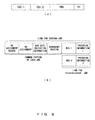
- FIG. 9(a) illustrates a data format of an example of a UCI for both links.
- the format includes individual CQI for the respective links. It also includes corresponding PMI and RI.
- the field information corresponding to the PMI and RI is the same for both links.
- the ACK or NAK (HARQ-ACK/NAK) included in the UCI for the HARQ process is the information about whether or not a reception error of a packet has occurred in the UE.
- the retransmission data packet decoding unit 302-4 and the new data packet decoding unit 303-5 in the reception device illustrated in FIG. 3 notifies the uplink control channel transmission unit 305 that it is necessary to retransmit a packet being processed when an error rate is equal to or higher than a predetermined threshold and the number of repetitions of a decoding process reaches a predetermined number in each decoding process.
- the uplink control channel transmission unit 305 transmits, to the serving eNB corresponding to the UE to which the unit belongs, a NAK for each received packet for which a retransmission is specified.
- the uplink control channel transmission unit 305 transmits an ACK for each received packet which has successfully received to the serving eNB corresponding to the UE including the unit.
- the HARQ-ACK/NAK included in the UCI is received by the uplink control channel reception unit 207 ( FIG. 2 ) in the serving eNB, and the information is passed to the transmission control unit 206.
- the transmission control unit 206 performs the retransmitting process on the HARQ as described above. In this case, it is preferable that the retransmitting process is performed only to the UE from the serving eNB as described in the scenario 2 for the following reasons.
- the field of the HARQ-ACK/NAK on the PUCCH is designed to include the ACK/NAK signal (2 bits) corresponding to both of the serving eNB and coordinated eNB for the transmission data packet corresponding to both of the serving eNB and coordinated eNB.
- the PDCCH is transmitted only from the serving eNB to de destination UE so that it can be indicated as a C2 in FIG. 8 .
- the PDCCH is terminated by the transmission control unit 206 ( FIG. 2 ) in the eNode-B operating as a serving eNB and the reception control unit 304 ( FIG. 3 ) in the UE.
- each UE decodes only the PDCCH from the serving eNB corresponding to the UE for the following two reasons.
- the downlink control information (DCI) transmitted through the PDCCH can indicate whether or not a coordinated transmission is currently being performed.
- DCI downlink control information
- a PCI includes a bit identifying whether a transmission packet is a new data packet or a retransmission data packet, that is, whether it is the scenario 1 or the scenario 2, or whether it is the scenario 1 or the scenario 3. It is used to indicate the reception device to perform or not to perform the HARQ processing.
- the information can be attained by using the new data indication information ( FIG. 9(b) described later) already prescribed and existing in the LTE standard.
- the DCI includes the following information
- the PDCCH including the DCI is stored together with a user data packet in a subframe regulated in the data format in, for example, the E-UTRA communication system, and then transmitted.
- Am X2 control channel (X2CCH) is delivered with a data packet corresponding to the control channel through the X2 interface indicated by C3 in FIG. 8 .
- the X2CCH is terminated by the X2 control channel transmission/reception unit 208 in the transmission device illustrated in FIG. 2 of the serving eNB and the coordinated eNB.
- the X2CCH is realized on the cable link using, for example, optical fiber.
- the X2CCH includes the following information.
- the transmission timing control is one of the most important problem for a coordinated transmission. It is determined by the serving eNB, and is instructed by the coordinated eNB through the X2 interface. The transmission timing is determined by considering the latency of the X2 interface.
- FIG. 10 is an example of the transmission timing between a control channel and a data channel.
- the data and the corresponding X2CCH are transferred to the coordinated eNB prior to the relating transmission (“PDCCH” and "Data from S-eNB") from the serving eNB to the UE with the timing t2.
- the transmission timing t1 of the data from the coordinated eNB (“Data from C-eNB") is determined by the serving eNB based on the maximum latency T of the X2 interface.
- the data from the serving eNB and the data from the coordinated eNB are delivered with predetermined timing t1 and t2. It guarantees the reception of both data with the simultaneous timing t3.
- the coordinated transmission for each UE is centrally controlled by the serving eNB.
- the control includes the scheduling of the UE and data, and the transmission timing control.
- a system level simulation has been performed to evaluate the performance of the above-mentioned coordinated HARQ transmission system according to the present embodiment.
- a system loaded with the transmission device ( FIG. 2 ) and the reception device ( FIG. 3 ) according to the present embodiment is implemented in the cell network formed by 7 clusters.
- Each cluster is configured by 19 hexagonal cells, and each cell includes 3 sectors.
- the bore-sight point of the antenna of the sector is directed at the vertex of the hexagon.
- a surrounding inclusive network structure is adopted to generate an accurate model of the generation of interference from an external cell, the cluster to be observed is arranged at the center, and six copies are symmetrically arranged at the sides of the central cluster.
- Tables 1 and 2 respectively illustrate the simulation case grouping and condition assumption.
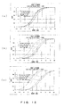
- FIG. 11 in (a), (b), and (c), illustrates the BLER for each UE as the function of the geometry about the initial transmission and the retransmission #1, #2, and #3 respectively in the cases 1, 2, and 3.
- Table 3 is a summary of the average BLER of the entire UE for the initial transmission and the retransmission #1, #2, and #3 in the cases 1, 2, and 3.
- the BLER for the initial transmission for the cases 1 and 3 is about 9%, and that for the case 2 is 78%. However, after the first retransmission, the BLER for the cases 1 and 3 is 0.1% or less, and that for the case 2 is 25%.
- the reception device for performing an appropriate SIC process according to the present embodiment it can be expected that the system performance for the coordinated transmission can be improved.
- the link gap target ⁇ is an important parameter having an influence on the coordinated transmission.
- the parameter is used to control the band width between the coordinated eNBs.
- the motive of performing the system level simulation is to clarify the gain attained by the scenario 2 with respect to the scenario 3.
- the CDF cumulative density function
- the SINR at the CDF point of 0.5 can be illustrated. This enables the merit of the SINR from the scenario 2 to be correctly indicated.
- FIG. 12 in (a), (b), and (c), illustrates the CDF of the SINR received by the UE in each case of the reception from the serving eNB and the coordinated eNB, in each case of with and without the SIC, and in each case of with each set value of ⁇ , or 1db, 10dB, and 19dB.
- the link gap target increases, the link quality between the serving eNB and the UE becomes better.
- the SIC process by the canceller unit 303-3 ( FIG. 3 ) operates in a better condition with respect to the link between the coordinated eNB and the UE.
- FIG. 13 is a graph indicating the probability of a UE falling into a link gap target ⁇ and determined as a cell edge user. For the UE, a coordinated transmission is performed.
- the link gap target ⁇ indicates a reasonable value about, for example, 8dB
- the rate of the cell edge user is about 60 %, which is sufficiently large value, and requires a coordinated transmission.
- FIG. 14 is a graph indicating the SINR of the UE as a function of the value of ⁇ as a function of the link gap target ⁇ when the CDF value is 50 %.
- FIG. 15 is a result of calculating the SINR gain of the UE for the two links with and without SIC in addition to the conditions of FIG. 14 .
- the present application has proposed the coordinated transmission system for the HARQ process to again a high SINR gain using the reception device for performing the SIC process.
- the present application realizes the SIC process more easily by using the unique behavior of the HARQ constantly indicating a low BLER after the combination of HARQs.
- a retransmission data packet is eventually delivered on the link constantly from the serving eNB to the UE and a new data packet is delivered on the link from the coordinated eNB to the UE during the delivery.
- an inverse process can be used.
- a physical uplink control channel PUCCH
- PDCH physical downlink control channel
- X2CCH X2 control channel
- the above-mentioned coordinated transmission system can also be applied to an intra-eNode-B in which a coordinated transmission occurs between two transmission points in the same eNode-B.
- a list of preferred embodiments is provided:
Landscapes
- Engineering & Computer Science (AREA)
- Signal Processing (AREA)
- Computer Networks & Wireless Communication (AREA)
- Mobile Radio Communication Systems (AREA)
- Detection And Prevention Of Errors In Transmission (AREA)
Priority Applications (2)
| Application Number | Priority Date | Filing Date | Title |
|---|---|---|---|
| EP14166571.1A EP2763342B8 (de) | 2008-10-28 | 2008-10-28 | Drahtloses Basisstationsgerät das koordinierte HARQ Kommunikation verwendet, ein drahtloses Terminal, drahtloses Kommunikationssystem und ein drachtloses Übertragungsverfahren |
| ES14166571.1T ES2638191T3 (es) | 2008-10-28 | 2008-10-28 | Dispositivo de estación base inalámbrico que utiliza comunicación HARQ coordinada, dispositivo terminal inalámbrico, sistema de comunicaciones inalámbricas, y método de comunicaciones inalámbricas |
Applications Claiming Priority (3)
| Application Number | Priority Date | Filing Date | Title |
|---|---|---|---|
| EP14166571.1A EP2763342B8 (de) | 2008-10-28 | 2008-10-28 | Drahtloses Basisstationsgerät das koordinierte HARQ Kommunikation verwendet, ein drahtloses Terminal, drahtloses Kommunikationssystem und ein drachtloses Übertragungsverfahren |
| EP08877683.6A EP2346272A4 (de) | 2008-10-28 | 2008-10-28 | Drahtlose basisstationseinrichtung mit einem kooperativen harq-kommunikationsverfahren, drahtloses endgerät, drahtloses kommunikationssystem und drahtloses kommunikationsverfahren |
| PCT/JP2008/003080 WO2010049970A1 (ja) | 2008-10-28 | 2008-10-28 | 協調的harq通信方式を用いた無線基地局装置、無線端末装置、無線通信システム、及び無線通信方法 |
Related Parent Applications (1)
| Application Number | Title | Priority Date | Filing Date |
|---|---|---|---|
| EP08877683.6A Division EP2346272A4 (de) | 2008-10-28 | 2008-10-28 | Drahtlose basisstationseinrichtung mit einem kooperativen harq-kommunikationsverfahren, drahtloses endgerät, drahtloses kommunikationssystem und drahtloses kommunikationsverfahren |
Publications (4)
| Publication Number | Publication Date |
|---|---|
| EP2763342A2 true EP2763342A2 (de) | 2014-08-06 |
| EP2763342A3 EP2763342A3 (de) | 2014-10-29 |
| EP2763342B1 EP2763342B1 (de) | 2017-05-24 |
| EP2763342B8 EP2763342B8 (de) | 2017-07-19 |
Family
ID=42128349
Family Applications (3)
| Application Number | Title | Priority Date | Filing Date |
|---|---|---|---|
| EP17166090.5A Active EP3211815B1 (de) | 2008-10-28 | 2008-10-28 | Drahtlose basisstationsvorrichtung mit einem koordinierten harq-kommunikationssystem, drahtlose endgerätevorrichtung, drahtloskommunikationssystem und drahtloskommunikationsverfahren |
| EP08877683.6A Withdrawn EP2346272A4 (de) | 2008-10-28 | 2008-10-28 | Drahtlose basisstationseinrichtung mit einem kooperativen harq-kommunikationsverfahren, drahtloses endgerät, drahtloses kommunikationssystem und drahtloses kommunikationsverfahren |
| EP14166571.1A Active EP2763342B8 (de) | 2008-10-28 | 2008-10-28 | Drahtloses Basisstationsgerät das koordinierte HARQ Kommunikation verwendet, ein drahtloses Terminal, drahtloses Kommunikationssystem und ein drachtloses Übertragungsverfahren |
Family Applications Before (2)
| Application Number | Title | Priority Date | Filing Date |
|---|---|---|---|
| EP17166090.5A Active EP3211815B1 (de) | 2008-10-28 | 2008-10-28 | Drahtlose basisstationsvorrichtung mit einem koordinierten harq-kommunikationssystem, drahtlose endgerätevorrichtung, drahtloskommunikationssystem und drahtloskommunikationsverfahren |
| EP08877683.6A Withdrawn EP2346272A4 (de) | 2008-10-28 | 2008-10-28 | Drahtlose basisstationseinrichtung mit einem kooperativen harq-kommunikationsverfahren, drahtloses endgerät, drahtloses kommunikationssystem und drahtloses kommunikationsverfahren |
Country Status (12)
| Country | Link |
|---|---|
| US (5) | US20110199975A1 (de) |
| EP (3) | EP3211815B1 (de) |
| JP (1) | JP5170251B2 (de) |
| KR (1) | KR101162003B1 (de) |
| CN (1) | CN102197617B (de) |
| AU (1) | AU2008363468B2 (de) |
| BR (1) | BRPI0823186A2 (de) |
| CA (1) | CA2741498C (de) |
| ES (2) | ES2638191T3 (de) |
| MX (1) | MX2011004367A (de) |
| RU (5) | RU2474975C2 (de) |
| WO (1) | WO2010049970A1 (de) |
Families Citing this family (45)
| Publication number | Priority date | Publication date | Assignee | Title |
|---|---|---|---|---|
| US8942165B2 (en) * | 2008-08-01 | 2015-01-27 | Qualcomm Incorporated | System and method for distributed multiple-input multiple-output (MIMO) in a wireless communication system |
| AU2008363468B2 (en) | 2008-10-28 | 2011-08-25 | Fujitsu Limited | Wireless base station device using cooperative HARQ communication method, wireless terminal device, wireless communication system, and wireless communication method |
| US8341481B2 (en) * | 2009-02-19 | 2012-12-25 | Samsung Electronics Co., Ltd. | Method for performing hybrid automatic repeat request operation in a wireless mobile communication system |
| US9071412B2 (en) * | 2009-04-27 | 2015-06-30 | Nokia Solutions And Networks Oy | Method of scheduling transmissions in a communication system |
| JP2011004161A (ja) * | 2009-06-18 | 2011-01-06 | Sharp Corp | 通信システム、通信装置および通信方法 |
| US9014138B2 (en) * | 2009-08-07 | 2015-04-21 | Blackberry Limited | System and method for a virtual carrier for multi-carrier and coordinated multi-point network operation |
| US9166677B2 (en) * | 2010-01-19 | 2015-10-20 | Qualcomm Incorporated | Method and apparatus for associating a relay in wireless communications |
| US8599763B2 (en) * | 2010-08-16 | 2013-12-03 | Qualcomm Incorporated | Timing control in a multi-point high speed downlink packet access network |
| KR20150091523A (ko) * | 2010-12-22 | 2015-08-11 | 후지쯔 가부시끼가이샤 | 액세스 노드들 간의 통신 인터페이스를 모니터링하기 위한 무선 통신 방법 |
| WO2012114152A1 (en) * | 2011-02-23 | 2012-08-30 | Research In Motion Limited | Enabling cooperative harq transmissions by assigning dccs |
| US20120226827A1 (en) * | 2011-03-02 | 2012-09-06 | Qualcomm Incorporated | Mechanism for Performing SDIO Aggregation and Conveying SDIO Device Status to the Host Software |
| EP2710853B1 (de) * | 2011-05-20 | 2017-11-08 | BlackBerry Limited | Harq mit mehreren empgänger-koordinierten sendern |
| US20130021987A1 (en) * | 2011-07-19 | 2013-01-24 | Industrial Technology Research Institute | Method of Performing Retransmissions by Using Different Resources and Related Communication Device |
| US20130021969A1 (en) * | 2011-07-19 | 2013-01-24 | Industrial Technology Research Institute | Method of Performing Retransmissions via Different Transmission Points and Related Communication Device |
| US9270346B2 (en) * | 2011-12-02 | 2016-02-23 | Apple Inc. | Methods for operating wireless electronic devices in coordinated multipoint transmission networks |
| CN103428836B (zh) * | 2012-05-16 | 2016-03-30 | 华为技术有限公司 | 基于harq的数据传输方法、设备和系统 |
| CN104782078B (zh) * | 2012-07-27 | 2019-02-26 | 爱立信(中国)通信有限公司 | 执行文件修复过程的用户设备节点、服务器节点以及方法 |
| JP6030882B2 (ja) * | 2012-07-31 | 2016-11-24 | 株式会社Nttドコモ | 無線通信システム、無線基地局装置及び再送制御方法 |
| EP2713651A1 (de) * | 2012-09-28 | 2014-04-02 | Alcatel Lucent | Verfahren zur Übergabeverwaltung innerhalb heterogener Netzwerke |
| JP6294834B2 (ja) * | 2012-12-28 | 2018-03-14 | 株式会社Nttドコモ | ユーザ装置、基地局、干渉低減方法、及び干渉低減制御情報通知方法 |
| CN105284070A (zh) * | 2013-03-14 | 2016-01-27 | Zte维创通讯公司 | 在利用有限的harq进程的分布式网络拓扑结构中使用更多传输机会的方法和装置 |
| WO2014182339A1 (en) * | 2013-05-09 | 2014-11-13 | Intel IP Corporation | Small data communications |
| CN104283655B (zh) * | 2013-07-10 | 2018-05-18 | 财团法人工业技术研究院 | 传送及接收混合自动重传请求回传的方法 |
| US9706537B2 (en) | 2013-07-10 | 2017-07-11 | Industrial Technology Research Institute | Method of handling HARQ feedbacks and related communication device |
| US9479293B2 (en) | 2013-07-10 | 2016-10-25 | Industrial Technology Research Institute | Method of handling HARQ feedbacks and related communication device |
| CN105580480B (zh) * | 2013-09-27 | 2020-04-21 | 阿尔卡特朗讯 | 用于确定物理下行链路控制信道的开始时间的方法 |
| JP6327257B2 (ja) * | 2014-01-15 | 2018-05-23 | 日本電気株式会社 | 無線端末及び基地局 |
| JP6319424B2 (ja) * | 2014-03-31 | 2018-05-09 | 富士通株式会社 | 無線通信システム、無線通信方法、無線局および制御局 |
| US9735930B2 (en) * | 2014-05-02 | 2017-08-15 | Telefonaktiebolaget Lm Ericsson (Publ) | System and method using a secondary network node for handling packet retransmissions |
| JP6473013B2 (ja) * | 2015-02-24 | 2019-02-20 | Kddi株式会社 | 制御装置、制御方法及びプログラム |
| CN107534681B (zh) * | 2015-04-27 | 2021-05-11 | 索尼公司 | 信息处理设备、通信系统、信息处理方法和程序 |
| WO2017022911A1 (ko) * | 2015-08-03 | 2017-02-09 | 엘지전자 주식회사 | 가상 단말 방식이 적용되는 경우의 단말의 재전송 데이터 수신 방법 |
| US9907084B2 (en) * | 2015-08-24 | 2018-02-27 | Telefonaktiebolaget Lm Ericsson (Publ) | Scheduling in high speed scenario |
| WO2017069559A1 (ko) | 2015-10-21 | 2017-04-27 | 엘지전자 주식회사 | 무선 통신 시스템에서 브로드캐스트 신호/멀티캐스트 신호에 대한 ack/nack 응답을 송신하는 방법 및 이를 위한 장치 |
| US10631323B2 (en) * | 2015-12-08 | 2020-04-21 | Qualcomm Incorporated | Delayed control feedback in a time division duplex carrier utilizing common bursts |
| EP3402109B1 (de) * | 2016-01-08 | 2021-12-01 | LG Electronics Inc. | Fehlerbehebungsverfahren und vorrichtung dafür mit verwendung eines multikanals in einem drahtloskommunikationssystem |
| US20190190662A1 (en) * | 2016-05-11 | 2019-06-20 | Lg Electronics Inc. | Method and apparatus for improving downlink broadcast for v2v communication in wireless communication system |
| CN107547169B (zh) * | 2016-06-28 | 2020-08-25 | 华为技术有限公司 | 一种数据重传方法和相关装置 |
| WO2018010143A1 (zh) | 2016-07-14 | 2018-01-18 | 广东欧珀移动通信有限公司 | 通信方法、基站和用户设备 |
| JP6571612B2 (ja) * | 2016-08-29 | 2019-09-04 | 日本電信電話株式会社 | 通信システム、通信システムの制御方法および通信装置 |
| CN110612683B (zh) * | 2017-05-31 | 2021-02-12 | 华为技术有限公司 | 一种上行数据的协作接收方法及网络设备 |
| CN114785460B (zh) * | 2017-06-15 | 2023-08-08 | 富士通株式会社 | 基站装置和终端装置 |
| CN110022615B (zh) * | 2018-01-08 | 2021-04-27 | 电信科学技术研究院 | 一种数据传输方法、装置、设备及计算机可读存储介质 |
| US11166194B1 (en) | 2020-04-02 | 2021-11-02 | Sprint Communications Company L.P. | Location-based error correction for wireless data communications |
| US12273293B2 (en) * | 2022-04-04 | 2025-04-08 | Dell Products, L.P. | Fast radio access network parameter control |
Citations (2)
| Publication number | Priority date | Publication date | Assignee | Title |
|---|---|---|---|---|
| JP2008503974A (ja) | 2004-06-25 | 2008-02-07 | エルジー エレクトロニクス インコーポレイティド | 直交周波数分割多重システムの無線リソース割り当て |
| JP2008517484A (ja) | 2004-08-17 | 2008-05-22 | エルジー エレクトロニクス インコーポレイティド | 無線通信システムにおける多重アンテナを用いたパケット伝送方法 |
Family Cites Families (47)
| Publication number | Priority date | Publication date | Assignee | Title |
|---|---|---|---|---|
| US5513379A (en) * | 1994-05-04 | 1996-04-30 | At&T Corp. | Apparatus and method for dynamic resource allocation in wireless communication networks utilizing ordered borrowing |
| US5867763A (en) * | 1996-02-08 | 1999-02-02 | Qualcomm Incorporated | Method and apparatus for integration of a wireless communication system with a cable T.V. system |
| US5987011A (en) * | 1996-08-30 | 1999-11-16 | Chai-Keong Toh | Routing method for Ad-Hoc mobile networks |
| FI108771B (fi) * | 1997-11-05 | 2002-03-15 | Nokia Corp | Menetelmä viestin lähettämiseksi matkaviestimelle |
| US20020169539A1 (en) * | 2001-03-28 | 2002-11-14 | Menard Raymond J. | Method and system for wireless tracking |
| ATE433274T1 (de) * | 1999-11-29 | 2009-06-15 | Samsung Electronics Co Ltd | Verfahren zur zuweisung eines gemeinsamen paketkanals in einem cdma-kommunikationssystem |
| US6973098B1 (en) | 2000-10-25 | 2005-12-06 | Qualcomm, Incorporated | Method and apparatus for determining a data rate in a high rate packet data wireless communications system |
| CA2436655A1 (en) | 2000-12-05 | 2002-06-13 | Qualcomm Incorporated | Method and apparatus for power level adjustment in a wireless communication system |
| EP1276249A1 (de) * | 2001-07-13 | 2003-01-15 | Reinhard Hecht | Vorrichtung zur Verbesserung der Übertragungseigenschaften eines Bündels elektrischer Datenleitungen und Anordnung zur Datenübertragung |
| US7006838B2 (en) * | 2002-11-27 | 2006-02-28 | Cognio, Inc. | System and method for locating sources of unknown wireless radio signals |
| US7457299B2 (en) * | 2003-06-25 | 2008-11-25 | General Dynamics C4 Systems, Inc. | Definable radio and method of operating a wireless network of same |
| KR101059877B1 (ko) * | 2004-08-17 | 2011-08-29 | 엘지전자 주식회사 | 3-안테나 시스템에서의 패킷 재전송 방법 |
| US7554985B2 (en) * | 2004-08-17 | 2009-06-30 | Lg Electronics Inc. | Packet transmission in a wireless communication system using multiple antennas |
| US8775890B2 (en) * | 2004-09-13 | 2014-07-08 | Inventergy, Inc. | Automatic retransmission request control system and retransmission method in MIMO-OFDM system |
| JP4647613B2 (ja) * | 2004-09-29 | 2011-03-09 | パナソニック株式会社 | 無線通信装置および無線通信方法 |
| US7428268B2 (en) | 2004-12-07 | 2008-09-23 | Adaptix, Inc. | Cooperative MIMO in multicell wireless networks |
| EP1916783A4 (de) | 2005-08-01 | 2013-01-09 | Sharp Kk | Zellulares mobilkommunikationssystem, basisstations-sendeeinrichtung und mobilstations-empfangseinrichtung in einem zellularen mobilkommunikationssystem und basisstationsauswahl-steuerverfahren in einem zellularen mobilkommunikationssystem |
| JP4305771B2 (ja) | 2005-08-01 | 2009-07-29 | シャープ株式会社 | セルラ移動通信システムにおける基地局の送信装置及び移動局の受信装置 |
| KR100976732B1 (ko) * | 2005-12-01 | 2010-08-18 | 삼성전자주식회사 | 다중 홉 방식의 네트워크에서 중계국을 이용한 재전송 장치및 방법 |
| US8831607B2 (en) | 2006-01-05 | 2014-09-09 | Qualcomm Incorporated | Reverse link other sector communication |
| CN101150384B (zh) * | 2006-09-20 | 2010-12-08 | 上海贝尔阿尔卡特股份有限公司 | 混合自动重传的方法和装置 |
| US8169964B2 (en) * | 2006-10-02 | 2012-05-01 | Troels Kolding | Adaptive scheme for lowering uplink control overhead |
| US20080155148A1 (en) | 2006-10-26 | 2008-06-26 | Ozgur Oyman | Cooperative communication of data |
| KR100906332B1 (ko) * | 2006-11-03 | 2009-07-06 | 삼성전자주식회사 | 중계기를 사용하는 광대역 무선통신 시스템에서 협력 복합자동 재전송 기법수행 장치 및 방법 |
| EP1944896A1 (de) * | 2007-01-09 | 2008-07-16 | Matsushita Electric Industrial Co., Ltd. | Konfiguration von Steuerkanälen in einem mobilen Kommunikationssystem |
| JP2008182542A (ja) * | 2007-01-25 | 2008-08-07 | Nec Corp | 移動通信システム及びそのソフトハンドオーバー方法 |
| CA2678024A1 (en) * | 2007-02-15 | 2008-08-21 | Ntt Docomo, Inc. | Base station apparatus, mobile station, radio communication system, and communication control method |
| JP2008227642A (ja) * | 2007-03-09 | 2008-09-25 | Hitachi Ltd | 再送制御方法、および無線通信システム |
| US20080225766A1 (en) * | 2007-03-15 | 2008-09-18 | Interdigital Technology Corporation | Method and apparatus for reconfiguring medium access control components in wireless communications |
| US8724556B2 (en) * | 2007-03-19 | 2014-05-13 | Apple Inc. | Uplink control channel allocation in a communication system and communicating the allocation |
| KR101467802B1 (ko) | 2007-04-12 | 2014-12-04 | 엘지전자 주식회사 | 광대역 무선접속 시스템에서 핸드오버 수행 및 지원 방법 |
| EP2627146B1 (de) * | 2007-06-18 | 2017-09-20 | LG Electronics Inc. | Verfahren und Benutzergerät zur Durchführung von Aufwärtsstreckensynchronisation in einem drahtlosen Kommunikationssystem |
| KR101645907B1 (ko) * | 2007-11-05 | 2016-08-04 | 애플 인크. | 자원 배정을 위한 방법들 및 시스템들 |
| KR101387532B1 (ko) * | 2007-12-26 | 2014-04-21 | 엘지전자 주식회사 | 협력적 mimo 수행을 위한 피드백 정보 전송방법 |
| KR101572291B1 (ko) * | 2008-01-02 | 2015-12-02 | 인터디지탈 테크날러지 코포레이션 | 협력적 무선 통신을 위한 방법 및 장치 |
| KR101375936B1 (ko) | 2008-02-01 | 2014-03-18 | 엘지전자 주식회사 | 시간동기 타이머의 만료 시 하향링크 harq의 동작 방법 |
| US8942165B2 (en) * | 2008-08-01 | 2015-01-27 | Qualcomm Incorporated | System and method for distributed multiple-input multiple-output (MIMO) in a wireless communication system |
| US8406171B2 (en) * | 2008-08-01 | 2013-03-26 | Texas Instruments Incorporated | Network MIMO reporting, control signaling and transmission |
| WO2010017101A2 (en) | 2008-08-05 | 2010-02-11 | Interdigital Patent Holdings, Inc. | Method and apparatus for implementing multi-cell cooperation techniques |
| KR20100019947A (ko) | 2008-08-11 | 2010-02-19 | 엘지전자 주식회사 | 무선 통신 시스템에서 정보 전송 방법 |
| US20100067604A1 (en) * | 2008-09-17 | 2010-03-18 | Texas Instruments Incorporated | Network multiple antenna transmission employing an x2 interface |
| US20100091678A1 (en) * | 2008-10-09 | 2010-04-15 | Texas Instruments Incorporated | Downlink rank indication and uplink rank reporting for dedicated beamforming |
| US9444587B2 (en) * | 2008-10-16 | 2016-09-13 | Qualcomm Incorporated | Incremental redundancy relays for wireless communication |
| KR101587680B1 (ko) * | 2008-10-20 | 2016-01-21 | 인터디지탈 패튼 홀딩스, 인크 | 반송파 집적 방법 |
| US8737296B2 (en) | 2008-10-24 | 2014-05-27 | Qualcomm Incorporated | Method and apparatus for anchor cell designation in network MIMO |
| WO2010048985A1 (en) * | 2008-10-27 | 2010-05-06 | Nokia Siemens Networks Oy | Method for network co-ordination in a mobile communications system and apparatus thereof |
| AU2008363468B2 (en) | 2008-10-28 | 2011-08-25 | Fujitsu Limited | Wireless base station device using cooperative HARQ communication method, wireless terminal device, wireless communication system, and wireless communication method |
-
2008
- 2008-10-28 AU AU2008363468A patent/AU2008363468B2/en not_active Ceased
- 2008-10-28 BR BRPI0823186-9A patent/BRPI0823186A2/pt not_active Application Discontinuation
- 2008-10-28 KR KR1020117011583A patent/KR101162003B1/ko active Active
- 2008-10-28 ES ES14166571.1T patent/ES2638191T3/es active Active
- 2008-10-28 CN CN200880131655.5A patent/CN102197617B/zh not_active Expired - Fee Related
- 2008-10-28 EP EP17166090.5A patent/EP3211815B1/de active Active
- 2008-10-28 ES ES17166090T patent/ES2715967T3/es active Active
- 2008-10-28 EP EP08877683.6A patent/EP2346272A4/de not_active Withdrawn
- 2008-10-28 EP EP14166571.1A patent/EP2763342B8/de active Active
- 2008-10-28 RU RU2011120185/08A patent/RU2474975C2/ru active
- 2008-10-28 JP JP2010535515A patent/JP5170251B2/ja not_active Expired - Fee Related
- 2008-10-28 WO PCT/JP2008/003080 patent/WO2010049970A1/ja not_active Ceased
- 2008-10-28 CA CA2741498A patent/CA2741498C/en active Active
- 2008-10-28 MX MX2011004367A patent/MX2011004367A/es active IP Right Grant
-
2011
- 2011-04-25 US US13/093,394 patent/US20110199975A1/en not_active Abandoned
-
2012
- 2012-09-28 RU RU2012141639/08A patent/RU2544746C2/ru not_active IP Right Cessation
- 2012-09-28 RU RU2012141576/08A patent/RU2526285C2/ru active
- 2012-09-28 RU RU2012141645/08A patent/RU2522297C2/ru active
-
2013
- 2013-11-18 US US14/083,063 patent/US9974072B2/en active Active
- 2013-11-26 US US14/091,006 patent/US20140079006A1/en not_active Abandoned
- 2013-12-05 US US14/098,207 patent/US9992771B2/en active Active
-
2015
- 2015-01-27 RU RU2015102619/08A patent/RU2584479C1/ru active
-
2017
- 2017-01-10 US US15/402,645 patent/US10034272B2/en active Active
Patent Citations (2)
| Publication number | Priority date | Publication date | Assignee | Title |
|---|---|---|---|---|
| JP2008503974A (ja) | 2004-06-25 | 2008-02-07 | エルジー エレクトロニクス インコーポレイティド | 直交周波数分割多重システムの無線リソース割り当て |
| JP2008517484A (ja) | 2004-08-17 | 2008-05-22 | エルジー エレクトロニクス インコーポレイティド | 無線通信システムにおける多重アンテナを用いたパケット伝送方法 |
Non-Patent Citations (10)
| Title |
|---|
| "Coordinated MIMO for LTE-A downlink", 3GPP TSG RAN WG1 MEETING #53BIS WARSAW, 30 June 2008 (2008-06-30) |
| "Network MIMO Precoding", 3GPP TSG RAN WG1 MEETING #53BIS WARSAW, 30 June 2008 (2008-06-30) |
| 3GPP TR 25.814 V7.0.0, June 2006 (2006-06-01) |
| 3GPP TR 36.913 V7.0.0, June 2008 (2008-06-01) |
| A. J. VITERBI; A. M. VITERBI; K. S. GILHOUSEN; E. ZEHAVI: "Soft handoff extends CDMA cell coverage and increases reverse link capacity", IEEE J. SEL. AREAS COMMUN., vol. 12, October 1994 (1994-10-01), pages 1281 - 1288 |
| D. WANG; X. YOU; J. WANG; Y. WANG; X. HOU: "Spectral Efficiency of Distributed MIMO Cellular Systems in a composite Fading Channel", IEEE INTERNATIONAL CONFERENCE ON, COMMUNICATIONS, 2008. ICC '08, 19 May 2008 (2008-05-19), pages 1259 - 1264, XP031265566 |
| O. SIMEONE; O. SOMEKH; H. V. POOR; S. SHAMAI: "Distributed MIMO in multi-cell wireless systems via finite-capacity links", COMMUNICATIONS, CONTROL AND SIGNAL PROCESSING, 2008. ISCCSP 2008. 3RD INTERNATIONAL SYMPOSIUM, 12 March 2008 (2008-03-12), pages 203 - 206, XP031269064 |
| SYED A. JAFAR; S. SHAMAI: "Degrees of freedom region for the MIMO X Channel", IEEE TRANSACTIONS ON INFORMATION THEORY, vol. 54, no. 1, January 2008 (2008-01-01), pages 151 - 170, XP011199561, DOI: doi:10.1109/TIT.2007.911262 |
| W. ROH; A. PAULRAJ: "MIMO channel capacity for the distributed antenna systems", IEEE VTC' 02, vol. 3, September 2002 (2002-09-01), pages 1520 - 1524 |
| Z. NI; D. LI: "Impact of fading correlation and power allocation on capacity of distributed MIMO", IEEE EMERGING TECHNOLOGIES: FRONTIERS OF MOBILE AND WIRELESS COMMUNICATION, 2004, vol. 2, 31 May 2004 (2004-05-31), pages 697 - 700, XP010716153, DOI: doi:10.1109/CASSET.2004.1321983 |
Also Published As
Similar Documents
| Publication | Publication Date | Title |
|---|---|---|
| EP2763342B1 (de) | Drahtloses Basisstationsgerät das koordinierte HARQ Kommunikation verwendet, ein drahtloses Terminal, drahtloses Kommunikationssystem und ein drachtloses Übertragungsverfahren | |
| AU2013201020B2 (en) | Wireless base station device using coordinated HARQ communication system, wireless terminal device, wireless communication system, and wireless communication method | |
| JP5761304B2 (ja) | 協調的harq通信方式を用いた無線基地局装置、無線端末装置、無線通信システム、及び無線通信方法 | |
| CN103338096B (zh) | 无线通信系统及其方法、无线终端装置和无线基站装置 | |
| JP5510605B2 (ja) | 協調的harq通信方式を用いた無線基地局装置、無線端末装置、無線通信システム、及び無線通信方法 | |
| JP5403138B2 (ja) | 協調的harq通信方式を用いた無線基地局装置、無線端末装置、無線通信システム、及び無線通信方法 | |
| JP5397530B2 (ja) | 協調的harq通信方式を用いた無線基地局装置、無線端末装置、無線通信システム、及び無線通信方法 | |
| JP5397529B2 (ja) | 協調的harq通信方式を用いた無線基地局装置、無線端末装置、無線通信システム、及び無線通信方法 | |
| JP5397524B2 (ja) | 協調的harq通信方式を用いた無線基地局装置、無線端末装置、無線通信システム、及び無線通信方法 | |
| CN103326835B (zh) | 无线通信系统及其方法、无线终端装置、无线基站装置 | |
| CN103281168A (zh) | 无线通信系统及其方法、无线通信终端装置和无线基站装置 |
Legal Events
| Date | Code | Title | Description |
|---|---|---|---|
| PUAI | Public reference made under article 153(3) epc to a published international application that has entered the european phase |
Free format text: ORIGINAL CODE: 0009012 |
|
| 17P | Request for examination filed |
Effective date: 20140430 |
|
| AC | Divisional application: reference to earlier application |
Ref document number: 2346272 Country of ref document: EP Kind code of ref document: P |
|
| AK | Designated contracting states |
Kind code of ref document: A2 Designated state(s): AT BE BG CH CY CZ DE DK EE ES FI FR GB GR HR HU IE IS IT LI LT LU LV MC MT NL NO PL PT RO SE SI SK TR |
|
| PUAL | Search report despatched |
Free format text: ORIGINAL CODE: 0009013 |
|
| AK | Designated contracting states |
Kind code of ref document: A3 Designated state(s): AT BE BG CH CY CZ DE DK EE ES FI FR GB GR HR HU IE IS IT LI LT LU LV MC MT NL NO PL PT RO SE SI SK TR |
|
| RIC1 | Information provided on ipc code assigned before grant |
Ipc: H04W 36/02 20090101ALI20140924BHEP Ipc: H04L 5/00 20060101ALI20140924BHEP Ipc: H04W 36/18 20090101ALI20140924BHEP Ipc: H04L 1/00 20060101ALI20140924BHEP Ipc: H04W 72/04 20090101ALI20140924BHEP Ipc: H04L 1/18 20060101AFI20140924BHEP |
|
| R17P | Request for examination filed (corrected) |
Effective date: 20150410 |
|
| RBV | Designated contracting states (corrected) |
Designated state(s): AT BE BG CH CY CZ DE DK EE ES FI FR GB GR HR HU IE IS IT LI LT LU LV MC MT NL NO PL PT RO SE SI SK TR |
|
| 17Q | First examination report despatched |
Effective date: 20150807 |
|
| GRAP | Despatch of communication of intention to grant a patent |
Free format text: ORIGINAL CODE: EPIDOSNIGR1 |
|
| INTG | Intention to grant announced |
Effective date: 20161222 |
|
| GRAS | Grant fee paid |
Free format text: ORIGINAL CODE: EPIDOSNIGR3 |
|
| GRAA | (expected) grant |
Free format text: ORIGINAL CODE: 0009210 |
|
| AC | Divisional application: reference to earlier application |
Ref document number: 2346272 Country of ref document: EP Kind code of ref document: P |
|
| AK | Designated contracting states |
Kind code of ref document: B1 Designated state(s): AT BE BG CH CY CZ DE DK EE ES FI FR GB GR HR HU IE IS IT LI LT LU LV MC MT NL NO PL PT RO SE SI SK TR |
|
| REG | Reference to a national code |
Ref country code: GB Ref legal event code: FG4D |
|
| RIN1 | Information on inventor provided before grant (corrected) |
Inventor name: WU, JIANMING |
|
| REG | Reference to a national code |
Ref country code: CH Ref legal event code: EP |
|
| RIN2 | Information on inventor provided after grant (corrected) |
Inventor name: WU, JIANMING |
|
| REG | Reference to a national code |
Ref country code: IE Ref legal event code: FG4D |
|
| REG | Reference to a national code |
Ref country code: AT Ref legal event code: REF Ref document number: 896473 Country of ref document: AT Kind code of ref document: T Effective date: 20170615 |
|
| REG | Reference to a national code |
Ref country code: DE Ref legal event code: R096 Ref document number: 602008050442 Country of ref document: DE |
|
| REG | Reference to a national code |
Ref country code: NL Ref legal event code: FP |
|
| REG | Reference to a national code |
Ref country code: FR Ref legal event code: PLFP Year of fee payment: 10 |
|
| REG | Reference to a national code |
Ref country code: LT Ref legal event code: MG4D |
|
| REG | Reference to a national code |
Ref country code: AT Ref legal event code: MK05 Ref document number: 896473 Country of ref document: AT Kind code of ref document: T Effective date: 20170524 |
|
| REG | Reference to a national code |
Ref country code: ES Ref legal event code: FG2A Ref document number: 2638191 Country of ref document: ES Kind code of ref document: T3 Effective date: 20171019 |
|
| PG25 | Lapsed in a contracting state [announced via postgrant information from national office to epo] |
Ref country code: LT Free format text: LAPSE BECAUSE OF FAILURE TO SUBMIT A TRANSLATION OF THE DESCRIPTION OR TO PAY THE FEE WITHIN THE PRESCRIBED TIME-LIMIT Effective date: 20170524 Ref country code: GR Free format text: LAPSE BECAUSE OF FAILURE TO SUBMIT A TRANSLATION OF THE DESCRIPTION OR TO PAY THE FEE WITHIN THE PRESCRIBED TIME-LIMIT Effective date: 20170825 Ref country code: FI Free format text: LAPSE BECAUSE OF FAILURE TO SUBMIT A TRANSLATION OF THE DESCRIPTION OR TO PAY THE FEE WITHIN THE PRESCRIBED TIME-LIMIT Effective date: 20170524 Ref country code: NO Free format text: LAPSE BECAUSE OF FAILURE TO SUBMIT A TRANSLATION OF THE DESCRIPTION OR TO PAY THE FEE WITHIN THE PRESCRIBED TIME-LIMIT Effective date: 20170824 Ref country code: AT Free format text: LAPSE BECAUSE OF FAILURE TO SUBMIT A TRANSLATION OF THE DESCRIPTION OR TO PAY THE FEE WITHIN THE PRESCRIBED TIME-LIMIT Effective date: 20170524 Ref country code: HR Free format text: LAPSE BECAUSE OF FAILURE TO SUBMIT A TRANSLATION OF THE DESCRIPTION OR TO PAY THE FEE WITHIN THE PRESCRIBED TIME-LIMIT Effective date: 20170524 |
|
| PG25 | Lapsed in a contracting state [announced via postgrant information from national office to epo] |
Ref country code: BG Free format text: LAPSE BECAUSE OF FAILURE TO SUBMIT A TRANSLATION OF THE DESCRIPTION OR TO PAY THE FEE WITHIN THE PRESCRIBED TIME-LIMIT Effective date: 20170824 Ref country code: IS Free format text: LAPSE BECAUSE OF FAILURE TO SUBMIT A TRANSLATION OF THE DESCRIPTION OR TO PAY THE FEE WITHIN THE PRESCRIBED TIME-LIMIT Effective date: 20170924 Ref country code: SE Free format text: LAPSE BECAUSE OF FAILURE TO SUBMIT A TRANSLATION OF THE DESCRIPTION OR TO PAY THE FEE WITHIN THE PRESCRIBED TIME-LIMIT Effective date: 20170524 Ref country code: LV Free format text: LAPSE BECAUSE OF FAILURE TO SUBMIT A TRANSLATION OF THE DESCRIPTION OR TO PAY THE FEE WITHIN THE PRESCRIBED TIME-LIMIT Effective date: 20170524 |
|
| PG25 | Lapsed in a contracting state [announced via postgrant information from national office to epo] |
Ref country code: SK Free format text: LAPSE BECAUSE OF FAILURE TO SUBMIT A TRANSLATION OF THE DESCRIPTION OR TO PAY THE FEE WITHIN THE PRESCRIBED TIME-LIMIT Effective date: 20170524 Ref country code: RO Free format text: LAPSE BECAUSE OF FAILURE TO SUBMIT A TRANSLATION OF THE DESCRIPTION OR TO PAY THE FEE WITHIN THE PRESCRIBED TIME-LIMIT Effective date: 20170524 Ref country code: CZ Free format text: LAPSE BECAUSE OF FAILURE TO SUBMIT A TRANSLATION OF THE DESCRIPTION OR TO PAY THE FEE WITHIN THE PRESCRIBED TIME-LIMIT Effective date: 20170524 Ref country code: EE Free format text: LAPSE BECAUSE OF FAILURE TO SUBMIT A TRANSLATION OF THE DESCRIPTION OR TO PAY THE FEE WITHIN THE PRESCRIBED TIME-LIMIT Effective date: 20170524 Ref country code: DK Free format text: LAPSE BECAUSE OF FAILURE TO SUBMIT A TRANSLATION OF THE DESCRIPTION OR TO PAY THE FEE WITHIN THE PRESCRIBED TIME-LIMIT Effective date: 20170524 |
|
| REG | Reference to a national code |
Ref country code: DE Ref legal event code: R097 Ref document number: 602008050442 Country of ref document: DE |
|
| PG25 | Lapsed in a contracting state [announced via postgrant information from national office to epo] |
Ref country code: PL Free format text: LAPSE BECAUSE OF FAILURE TO SUBMIT A TRANSLATION OF THE DESCRIPTION OR TO PAY THE FEE WITHIN THE PRESCRIBED TIME-LIMIT Effective date: 20170524 |
|
| PLBE | No opposition filed within time limit |
Free format text: ORIGINAL CODE: 0009261 |
|
| STAA | Information on the status of an ep patent application or granted ep patent |
Free format text: STATUS: NO OPPOSITION FILED WITHIN TIME LIMIT |
|
| 26N | No opposition filed |
Effective date: 20180227 |
|
| PG25 | Lapsed in a contracting state [announced via postgrant information from national office to epo] |
Ref country code: SI Free format text: LAPSE BECAUSE OF FAILURE TO SUBMIT A TRANSLATION OF THE DESCRIPTION OR TO PAY THE FEE WITHIN THE PRESCRIBED TIME-LIMIT Effective date: 20170524 Ref country code: MC Free format text: LAPSE BECAUSE OF FAILURE TO SUBMIT A TRANSLATION OF THE DESCRIPTION OR TO PAY THE FEE WITHIN THE PRESCRIBED TIME-LIMIT Effective date: 20170524 |
|
| REG | Reference to a national code |
Ref country code: CH Ref legal event code: PL |
|
| REG | Reference to a national code |
Ref country code: IE Ref legal event code: MM4A |
|
| PG25 | Lapsed in a contracting state [announced via postgrant information from national office to epo] |
Ref country code: LI Free format text: LAPSE BECAUSE OF NON-PAYMENT OF DUE FEES Effective date: 20171031 Ref country code: CH Free format text: LAPSE BECAUSE OF NON-PAYMENT OF DUE FEES Effective date: 20171031 Ref country code: LU Free format text: LAPSE BECAUSE OF NON-PAYMENT OF DUE FEES Effective date: 20171028 |
|
| REG | Reference to a national code |
Ref country code: BE Ref legal event code: MM Effective date: 20171031 |
|
| PG25 | Lapsed in a contracting state [announced via postgrant information from national office to epo] |
Ref country code: BE Free format text: LAPSE BECAUSE OF NON-PAYMENT OF DUE FEES Effective date: 20171031 |
|
| REG | Reference to a national code |
Ref country code: FR Ref legal event code: PLFP Year of fee payment: 11 |
|
| PG25 | Lapsed in a contracting state [announced via postgrant information from national office to epo] |
Ref country code: MT Free format text: LAPSE BECAUSE OF NON-PAYMENT OF DUE FEES Effective date: 20171028 |
|
| PG25 | Lapsed in a contracting state [announced via postgrant information from national office to epo] |
Ref country code: IE Free format text: LAPSE BECAUSE OF NON-PAYMENT OF DUE FEES Effective date: 20171028 |
|
| PG25 | Lapsed in a contracting state [announced via postgrant information from national office to epo] |
Ref country code: HU Free format text: LAPSE BECAUSE OF FAILURE TO SUBMIT A TRANSLATION OF THE DESCRIPTION OR TO PAY THE FEE WITHIN THE PRESCRIBED TIME-LIMIT; INVALID AB INITIO Effective date: 20081028 |
|
| PG25 | Lapsed in a contracting state [announced via postgrant information from national office to epo] |
Ref country code: CY Free format text: LAPSE BECAUSE OF NON-PAYMENT OF DUE FEES Effective date: 20170524 |
|
| PG25 | Lapsed in a contracting state [announced via postgrant information from national office to epo] |
Ref country code: TR Free format text: LAPSE BECAUSE OF FAILURE TO SUBMIT A TRANSLATION OF THE DESCRIPTION OR TO PAY THE FEE WITHIN THE PRESCRIBED TIME-LIMIT Effective date: 20170524 |
|
| PG25 | Lapsed in a contracting state [announced via postgrant information from national office to epo] |
Ref country code: PT Free format text: LAPSE BECAUSE OF FAILURE TO SUBMIT A TRANSLATION OF THE DESCRIPTION OR TO PAY THE FEE WITHIN THE PRESCRIBED TIME-LIMIT Effective date: 20170524 |
|
| REG | Reference to a national code |
Ref country code: DE Ref legal event code: R082 Ref document number: 602008050442 Country of ref document: DE Representative=s name: HL KEMPNER PATENTANWAELTE, SOLICITORS (ENGLAND, DE Ref country code: DE Ref legal event code: R082 Ref document number: 602008050442 Country of ref document: DE Representative=s name: HL KEMPNER PATENTANWALT, RECHTSANWALT, SOLICIT, DE Ref country code: DE Ref legal event code: R082 Ref document number: 602008050442 Country of ref document: DE Representative=s name: HL KEMPNER PARTG MBB, DE |
|
| PGFP | Annual fee paid to national office [announced via postgrant information from national office to epo] |
Ref country code: ES Payment date: 20221102 Year of fee payment: 15 |
|
| PGFP | Annual fee paid to national office [announced via postgrant information from national office to epo] |
Ref country code: NL Payment date: 20230915 Year of fee payment: 16 Ref country code: IT Payment date: 20230913 Year of fee payment: 16 |
|
| REG | Reference to a national code |
Ref country code: ES Ref legal event code: FD2A Effective date: 20241216 |
|
| PG25 | Lapsed in a contracting state [announced via postgrant information from national office to epo] |
Ref country code: ES Free format text: LAPSE BECAUSE OF NON-PAYMENT OF DUE FEES Effective date: 20231029 |
|
| PG25 | Lapsed in a contracting state [announced via postgrant information from national office to epo] |
Ref country code: ES Free format text: LAPSE BECAUSE OF NON-PAYMENT OF DUE FEES Effective date: 20231029 |
|
| REG | Reference to a national code |
Ref country code: NL Ref legal event code: MM Effective date: 20241101 |
|
| PG25 | Lapsed in a contracting state [announced via postgrant information from national office to epo] |
Ref country code: NL Free format text: LAPSE BECAUSE OF NON-PAYMENT OF DUE FEES Effective date: 20241101 |
|
| PG25 | Lapsed in a contracting state [announced via postgrant information from national office to epo] |
Ref country code: IT Free format text: LAPSE BECAUSE OF NON-PAYMENT OF DUE FEES Effective date: 20241028 |
|
| PGFP | Annual fee paid to national office [announced via postgrant information from national office to epo] |
Ref country code: GB Payment date: 20250923 Year of fee payment: 18 |
|
| PGFP | Annual fee paid to national office [announced via postgrant information from national office to epo] |
Ref country code: FR Payment date: 20250924 Year of fee payment: 18 |
|
| REG | Reference to a national code |
Ref country code: DE Ref legal event code: R081 Ref document number: 602008050442 Country of ref document: DE Owner name: 1FINITY INC., KAWASAKI-SHI, JP Free format text: FORMER OWNER: FUJITSU LIMITED, KAWASAKI-SHI, KANAGAWA, JP |
|
| REG | Reference to a national code |
Ref country code: GB Ref legal event code: 732E Free format text: REGISTERED BETWEEN 20251127 AND 20251203 |
|
| PGFP | Annual fee paid to national office [announced via postgrant information from national office to epo] |
Ref country code: DE Payment date: 20250923 Year of fee payment: 18 |