EP2765946B1 - Medizinisches verfolgungssystem mit einer multifunktionellen sensorvorrichtung - Google Patents
Medizinisches verfolgungssystem mit einer multifunktionellen sensorvorrichtung Download PDFInfo
- Publication number
- EP2765946B1 EP2765946B1 EP11769880.3A EP11769880A EP2765946B1 EP 2765946 B1 EP2765946 B1 EP 2765946B1 EP 11769880 A EP11769880 A EP 11769880A EP 2765946 B1 EP2765946 B1 EP 2765946B1
- Authority
- EP
- European Patent Office
- Prior art keywords
- sensor
- marker
- marker device
- sensor device
- data
- Prior art date
- Legal status (The legal status is an assumption and is not a legal conclusion. Google has not performed a legal analysis and makes no representation as to the accuracy of the status listed.)
- Active
Links
Images


Classifications
-
- G—PHYSICS
- G06—COMPUTING OR CALCULATING; COUNTING
- G06V—IMAGE OR VIDEO RECOGNITION OR UNDERSTANDING
- G06V40/00—Recognition of biometric, human-related or animal-related patterns in image or video data
- G06V40/10—Human or animal bodies, e.g. vehicle occupants or pedestrians; Body parts, e.g. hands
- G06V40/103—Static body considered as a whole, e.g. static pedestrian or occupant recognition
-
- A—HUMAN NECESSITIES
- A61—MEDICAL OR VETERINARY SCIENCE; HYGIENE
- A61B—DIAGNOSIS; SURGERY; IDENTIFICATION
- A61B34/00—Computer-aided surgery; Manipulators or robots specially adapted for use in surgery
- A61B34/20—Surgical navigation systems; Devices for tracking or guiding surgical instruments, e.g. for frameless stereotaxis
-
- A—HUMAN NECESSITIES
- A61—MEDICAL OR VETERINARY SCIENCE; HYGIENE
- A61B—DIAGNOSIS; SURGERY; IDENTIFICATION
- A61B17/00—Surgical instruments, devices or methods
- A61B17/14—Surgical saws
- A61B17/15—Guides therefor
- A61B17/154—Guides therefor for preparing bone for knee prosthesis
-
- A—HUMAN NECESSITIES
- A61—MEDICAL OR VETERINARY SCIENCE; HYGIENE
- A61B—DIAGNOSIS; SURGERY; IDENTIFICATION
- A61B17/00—Surgical instruments, devices or methods
- A61B2017/00017—Electrical control of surgical instruments
- A61B2017/00199—Electrical control of surgical instruments with a console, e.g. a control panel with a display
-
- A—HUMAN NECESSITIES
- A61—MEDICAL OR VETERINARY SCIENCE; HYGIENE
- A61B—DIAGNOSIS; SURGERY; IDENTIFICATION
- A61B34/00—Computer-aided surgery; Manipulators or robots specially adapted for use in surgery
- A61B34/20—Surgical navigation systems; Devices for tracking or guiding surgical instruments, e.g. for frameless stereotaxis
- A61B2034/2046—Tracking techniques
- A61B2034/2048—Tracking techniques using an accelerometer or inertia sensor
-
- A—HUMAN NECESSITIES
- A61—MEDICAL OR VETERINARY SCIENCE; HYGIENE
- A61B—DIAGNOSIS; SURGERY; IDENTIFICATION
- A61B34/00—Computer-aided surgery; Manipulators or robots specially adapted for use in surgery
- A61B34/20—Surgical navigation systems; Devices for tracking or guiding surgical instruments, e.g. for frameless stereotaxis
- A61B2034/2046—Tracking techniques
- A61B2034/2055—Optical tracking systems
- A61B2034/2057—Details of tracking cameras
-
- A—HUMAN NECESSITIES
- A61—MEDICAL OR VETERINARY SCIENCE; HYGIENE
- A61B—DIAGNOSIS; SURGERY; IDENTIFICATION
- A61B34/00—Computer-aided surgery; Manipulators or robots specially adapted for use in surgery
- A61B34/20—Surgical navigation systems; Devices for tracking or guiding surgical instruments, e.g. for frameless stereotaxis
- A61B2034/2068—Surgical navigation systems; Devices for tracking or guiding surgical instruments, e.g. for frameless stereotaxis using pointers, e.g. pointers having reference marks for determining coordinates of body points
-
- A—HUMAN NECESSITIES
- A61—MEDICAL OR VETERINARY SCIENCE; HYGIENE
- A61B—DIAGNOSIS; SURGERY; IDENTIFICATION
- A61B34/00—Computer-aided surgery; Manipulators or robots specially adapted for use in surgery
- A61B34/20—Surgical navigation systems; Devices for tracking or guiding surgical instruments, e.g. for frameless stereotaxis
- A61B2034/2072—Reference field transducer attached to an instrument or patient
-
- A—HUMAN NECESSITIES
- A61—MEDICAL OR VETERINARY SCIENCE; HYGIENE
- A61B—DIAGNOSIS; SURGERY; IDENTIFICATION
- A61B90/00—Instruments, implements or accessories specially adapted for surgery or diagnosis and not covered by any of the groups A61B1/00 - A61B50/00, e.g. for luxation treatment or for protecting wound edges
- A61B90/39—Markers, e.g. radio-opaque or breast lesions markers
- A61B2090/3983—Reference marker arrangements for use with image guided surgery
-
- A—HUMAN NECESSITIES
- A61—MEDICAL OR VETERINARY SCIENCE; HYGIENE
- A61B—DIAGNOSIS; SURGERY; IDENTIFICATION
- A61B90/00—Instruments, implements or accessories specially adapted for surgery or diagnosis and not covered by any of the groups A61B1/00 - A61B50/00, e.g. for luxation treatment or for protecting wound edges
- A61B90/39—Markers, e.g. radio-opaque or breast lesions markers
- A61B2090/3995—Multi-modality markers
Definitions
- the present invention relates to a medical tracking system comprising at least one multifunctional sensor device which can be used as both a marker device and/or a marker detector device.
- the present invention further relates to a method for medical tracking using such a medical tracking system.
- the strict division into marker devices and marker device detectors is broken by using a sensor device which can act as a marker device as well as a marker detection device.
- the medical tracking system comprises at least one sensor device which can be positioned in a fixed position relative to a target.
- the sensor device comprises a marker device and a marker device detector.
- the marker device detector is capable of obtaining information for determining a relative position between the marker device detector and another marker device. This information may be sufficient to determine the relative position or it may be necessary to supplement this information by further information.
- the other marker device is a marker device other than the one comprised in the sensor device.
- a target can be medical instrument such as a cutting block or a pointer, a part of an operation room equipment such as an operation room table or tripod or an anatomical structure such as a bone. If a sensor device is rigidly attached to a medical instrument and the medical instrument is rigidly attached to an anatomical structure, this means that the sensor device is automatically in a fixed position relative to the anatomical structure.
- a fixed position in this document means that two objects which are in a fixed position have a relative position which does not change unless this change is explicitly and intentionally initiated.
- a fixed position is in particular given if a force or torque above a predetermined threshold has to be applied in order to change the position. This threshold might be 10 N or 10 Nm.
- the position of a sensor device remains fixed relative to a target while the target is registered or two targets are moved relative to each other as explained below.
- a fixed position can for example be achieved by rigidly attaching one object to another.
- the term "position" in this document means a spatial location in up to three (in particular less than three) translational dimensions and/or an alignment in up to three (in particular less than three) rotational dimensions.
- the position can thus comprise up to six dimensions, wherein there is a parameter for each dimension. Depending on the application or workflow, the parameters of less than six dimensions may be required or desired.
- the spatial location can in particular be described just by a distance (between two objects) or just by the direction of a vector (which links two objects).
- the alignment can in particular be described by just the relative angle of orientation (between the two objects).
- a marker device can for example be one or more (individual) markers in a predetermined spatial relationship.
- a marker device comprises one, two, three or more markers in a predetermined spatial relationship. This predetermined spatial relationship is in particular known to the tracking system and for example stored in a control unit of the tracking system.
- a marker detection device for example, a camera
- its spatial position i.e. its spatial location and/or alignment
- information used for ascertaining its spatial position is provided, while the information provided by a single marker detection device might not be sufficient to ascertain all parameters which define the spatial position.
- the detection device is in particular part of a navigation system.
- the markers can be active markers.
- An active marker can for example emit electromagnetic radiation and/or waves, wherein said radiation can be in the infrared, visible and/or ultraviolet spectral range.
- the marker can also however be passive, i.e. can for example reflect electromagnetic radiation in the infrared, visible and/or ultraviolet spectral range.
- the marker can be provided with a surface which has corresponding reflective properties. It is also possible for a marker to reflect and/or emit electromagnetic radiation and/or waves in the radio frequency range or at ultrasound wavelengths.
- a marker preferably has a spherical and/or spheroid shape and can therefore be referred to as a marker sphere; markers can also, however, exhibit a cornered - for example, cubic - shape.
- the marker device detector is either just a sensor which outputs sensor data which are then analyzed by a processing unit in order to determine the position of a marker device or includes the processing unit, such that the marker device detector directly outputs the position of a marker device.
- the medical tracking system further comprises a control unit configured to process a medical navigation workflow, which consists of two or more workflow steps, and to select the function of the sensor device as either acting as a marker device detector or as a marker device in a step of the medical navigation workflow.
- the control unit is preferably further configured to determine the relative position between the other marker device and the marker device detector from the information output by the marker device detector.
- the number of instruments needed to perform the medical navigation workflow can be reduced, which means that less instruments have to be provided and sterilized.
- processing of the medical navigation workflow is accelerated because less instruments have to be handled, which means that the used instruments have to be changed less often.
- either acting as a marker device detector or as a marker device means that the sensor device has the function of either a marker device detector means or a marker device means.
- acting thus has the meaning of "behaving as”.
- the sensor device comprises display for displaying at least a part of the marker device.
- one or more markers are displayed on the display.
- the displayed markers may supplement static markers on the sensor device.
- the markers making up the marker device are optical markers, which means mat the marker device is an optical marker device, and the marker device detector is a still or video camera, and in particular a 2D camera.
- the camera captures an image of the optical marker device and calculates the position of the optical marker device. This is done by analyzing the configuration, shapes and sizes of the markers in the camera image.
- the optical marker device comprises a plurality of squares in a known configuration. Further preferably, each of the squares has one of at least two different sizes. Yet further preferably, the squares are arranged in different planes, which are preferably parallel to each other.
- the tracking system comprises at least two sensor devices, wherein, in a particular step of the medical navigation workflow, one sensor device acts as a marker device and another sensor device acts as a marker device detector.
- the function of the two sensor devices changes between the two steps of the medical navigation workflow. This is particularly useful if, in one step of the workflow, a marker device has to be rigidly attached to a target, while in the next workflow step a marker device detector has to be attached to the target, or vice versa.
- the subsequent attachment of two different devices can be replaced by switching between the two different functions of the same sensor device.
- one of the sensor devices is positioned in a fixed position relative to a target and another sensor device acts as a pointer. This is particularly useful if an object, such as the target to which the sensor device is positioned in a fixed relative position, is to be registered and the sensor device acting as a pointer is used for registration.
- a pointer is a rod which comprises a marker device fastened to it and can be used to measure off individual co-ordinates, in particular spatial co-ordinates (i.e. three-dimensional co-ordinates), on a part of the body, wherein a user guides the pointer (in particular, a part of the pointer which has a defined and advantageously fixed location with respect to the marker device attached to the pointer) to the position corresponding to the co-ordinates, such that the position of the pointer can be determined by using the tracking system to detect the marker device of the pointer.
- the relative location between the marker device of the pointer and the part of the pointer used to measure off co-ordinates is in particular known.
- a sensor device further comprises an orientation sensor.
- This orientation sensor outputs orientation sensor data which represents the orientation of the sensor, and therefore of the sensor device, in up to three rotational dimensions.
- the reference system in which the orientation sensor data is determined is preferably an absolute, stationary reference system, such as ground-based reference system utilizing the direction of gravity.
- the sensor device comprising an orientation sensor
- it preferably transmits the orientation sensor data to a sensor device acting as a marker detection device or to the control unit of the medical tracking system.
- the detection of the position of the sensor device acting as a marker device can be supplemented by the orientation sensor data; thus making the detection result more reliable.
- the orientation sensor data can be used to calculate the position of the detected marker device in an absolute reference system known to the sensor device acting as a marker detection device.
- an off-the-shelf (consumer) device as a sensor device, such as an iPod touch or an iPhone provided by Apple Inc.
- the present invention further relates to a method of medical tracking for supporting a medical navigation workflow.
- the method comprises the step of using a sensor device comprising an optical marker device and a marker device detector being a still or video camera as a marker device detector in one step of the medical navigation workflow for obtaining information for determining the position of an optical marker device and using the same sensor device as an optical marker device in another step of the medical navigation workflow.
- the sensor device thus has a double functionality, wherein the appropriate functionality is chosen depending on the requirements of a particular step of the medical navigation workflow.
- the functionality is preferably chosen by a control unit which processes the medical navigation workflow.
- the method utilizes two sensor devices, one of the sensor devices acting as a marker device of a pointer for pointing at sample points and another one of the sensor devices, being positioned in a fixed position relative to a target, acting as a marker device detector for obtaining information for determining the position of the marker device.
- a first sensor device acting as a marker detection device is preferably rigidly attached to an anatomical structure such as a bone or to a medical instrument such as a cutting block, which in turn can be rigidly attached to an anatomical structure.
- a second sensor device acting as a marker device is preferably rigidly attached to a pointer, wherein the second sensor device has a known relative position to the pointer, in particular to the tip of the pointer.
- the method comprises the step of registering the target by sampling a plurality of sample points, which preferably lie on the surface of the target
- the sensor device acting as a marker device and the sensor device acting as a marker device detector both comprise an orientation sensor and the orientation sensor data are used when the position of a marker device is determined.
- the orientation sensors preferably generate orientation sensor data in an absolute reference system as explained above. This means that the position of the marker device can be determined from the two sets of orientation sensor data as well as from the information output by the marker device detector. The two determined positions can be combined, for example for increasing the accuracy of the determined position or for validating one of the determined positions with the other one of the determined positions.
- the sensor device further comprises a display device and is positioned in a fixed position relative to a bone, wherein the image captured by the camera is displayed on the display device and a characteristic property of the bone can be acquired based on the camera image on the display device.
- a characteristic property of the bone can be acquired based on the camera image on the display device.
- the additional feature of this embodiment that is acquiring a characteristic property of a bone to which a sensor device comprising a display and a camera is attached based on a camera image showing at least a part of the bone or an anatomical structure, such as a foot or a hand, attached to the bone, can also be utilized apart from this invention as a stand-alone invention or in combination with other inventions.
- an information which is overlaid over the camera image is manipulated by using an input device of the sensor device, such as a button, a dial or a touch functionality of the display.
- This information is preferably an arrow which can be aligned on the camera image by using the input device.
- the characteristic property of the bone is acquired automatically, for example by an automatic analysis of the camera image.
- the invention also relates to a program which, when running on a computer or when loaded onto a computer, causes the computer to perform one or more or all of the method steps described herein and/or to a program storage medium on which the program is stored (in particular in a non-transitory form) and/or to a computer on which the program is running or into d e memory of which the program is loaded and/or to a signal wave, in particular a digital signal wave, carrying information which represents the program, in particular the aforementioned program, which in particular comprises code means which are adapted to perform any or all of the method steps described herein.
- computer program elements can be embodied by hardware and/or software (this includes firmware, resident software, micro-code, etc.).
- computer program elements can take the form of a computer program product which can be embodied by a computer-usable, in particular computer-readable data storage medium comprising computer-usable, in particular computer-readable program instructions, "code” or a "computer program” embodied in said data storage medium for use on or in connection with the instruction-executing system.
- Such a system can be a computer; a computer can be a data processing device comprising means for executing the computer program elements and/or the program in accordance with the invention, in particular a data processing device comprising a digital processor (central processing unit - CPU) which executes the computer program elements and optionally a volatile memory (in particular, a random access memory - RAM) for storing data used for and/or produced by executing the computer program elements.
- a computer-usable, in particular computer-readable data storage medium can be any data storage medium which can include, store, communicate, propagate or transport the program for use on or in connection with the instruction-executing system, apparatus or device.
- the computer-usable, in particular computer-readable data storage medium can for example be, but is not limited to, an electronic, magnetic, optical, electromagnetic, infrared or semiconductor system, apparatus or device or a medium of propagation such as for example the Internet.
- the computer-usable or computer-readable data storage medium could even for example be paper or another suitable medium onto which the program is printed, since the program could be electronically captured, for example by optically scanning the paper or other suitable medium, and then compiled, interpreted or otherwise processed in a suitable manner.
- the data storage medium is a non-volatile data storage medium.
- the computer program product and any software and/or hardware described here form the various means for performing the functions of the invention in the example embodiments.
- the computer and/or data processing device can in particular include a guidance information device which includes means for outputting guidance information.
- the guidance information can be outputted, for example to a user, visually by a visual indicating means (for example, a monitor and/or a lamp) and/or acoustically by an acoustic indicating means (for example, a loudspeaker and/or a digital speech output device) and/or tactilely by a tactile indicating means (for example, a vibrating element or vibration element incorporated into an instrument).
- a visual indicating means for example, a monitor and/or a lamp
- an acoustic indicating means for example, a loudspeaker and/or a digital speech output device
- tactilely by a tactile indicating means for example, a vibrating element or vibration element incorporated into an instrument.
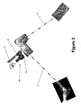
- Figure 1 schematically shows a medical tracking system, also referred to as a medical navigation system, comprising two sensor devices 1 and 2.
- the structure of the sensor devices 1 and 2 is shown schematically in Figure 2 .
- a sensor device 1, 2 comprises a processor or central processing unit (CPU) 3 which is connected to a display 4, the gyroscope 5, two cameras 6 and 7 and a Bluetooth transceiver 8.
- the 2D-cameras 6 and 7 are located on opposite sides of a housing of the sensor device 1, 2.
- camera 6 is located on the same side as the display 4.
- the cameras 6 and 7 act as position sensors.
- a sensor device 1,2 further comprises an optional distance sensor 19.
- the gyroscope 5 is configured to determine orientation data which represent the orientation of the sensor device 1, 2 in three rotational dimensions in an absolute, ground-fixed reference system based on the direction of gravity.
- the gyroscope 5 acts as an orientation sensor.
- the processor 3 acts as control unit. This means that both sensor devices 1, 2 comprise a control unit.
- At least one of the sensor devices 1, 2 comprises optical markers 9, which in the present case are rectangles or squares.
- the markers 9 have the same size and are arranged in a known pattern. This pattern is preferably three-dimensional, which means that the markers 9 are preferably arranged in two or more (parallel) planes. The sizes of some or all of the markers 9 can also be different.
- the shape of a sensor device can also be used as a marker.
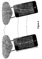
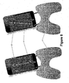
- Figures 3 to 12 show different steps of a first medical navigation workflow.
- the properties of a knee joint between a femur F and a tibia T are determined.
- an adjustable cutting block 10 is attached to the tibia T.
- the adjustable cutting block 10 comprises a base 11 and an adjustable cutting slot 12 which is adjustable relative to the base 11.
- the first sensor device 1 is rigidly attached to the cutting slot 12 of the cutting block 10 in a reproducible position relative to the slot 12.
- the field of view of the camera 7 is indicated schematically by the eye symbol.
- the sensor device 1 acquires the anterioposterior (AP) axis or direction as a property of the tibia T.
- the AP direction can be determined automatically, for example if the patient is lying flat on his back. In this case, the AP direction can be acquired as being parallel or in a known relation to gravity.
- the AP direction is acquired based on manually inputted AP data.
- an arrow virtually representing the AP direction is displayed on the display 4.
- a user can then input data to align the AP arrow shown on the display 4 with the actual AP direction of the tibia T.
- the AP arrow can be rotated in the display plane, for example by using buttons (not shown) of the sensor device 1 or by touching the display 4 if the display 4 is a touch sensitive display.
- the AP arrow is overlaid on an image captured by the camera 7 which is located in the housing of the sensor device 1 on an opposite side of the display 4.
- This image typically shows a part of the tibia, and preferably also a part of the foot.
- This overlay leads to an improved accuracy of the manually inputted AP direction.
- the AP direction can be automatically determined from an image analysis performed by the CPU 3.
- any property of an anatomical structure can be acquired by manipulating information, such as an arrow, displayed on the display of a sensor device.
- the second sensor device 2 which comprises markers 9 as explained with reference to Figure 2 , is rigidly attached to a pointer 13.
- the relative position between the markers 9 and the tip of the pointer 13 is known. Additional markers, such as the circles 14, can be displayed on the display 4 of the sensor device 2.
- the second sensor device 2 acts as a marker device and the first sensor device 1 acts as a marker device detector.
- the pointer 13 comprises an adaptor for accommodating a sensor device 1 or 2 in an unambiguous, reproducible position relative to its tip. Some or all of the fixed markers 9 may be located on the pointer 13.
- landmarks of the tibia T are sampled by touching the landmark with the tip of the pointer 13 and determining the position of the markers 9 and 14. Due to the known constellation of the markers relative to the tip of the pointer 13, the position of the tip can be determined from the position of the markers.
- the positions of the markers are determined by the sensor device 1.
- the camera 7 of the sensor device 1 captures an image comprising the markers. Due to the known constellation and sizes of the markers, the CPU 3 of the sensor device 1 can analyze the output image of the camera 7 in order to detect the markers and hence the positions of the landmarks in a reference system of the sensor device 1.
- the CPU 3 uses the size, the shape and the relative positions of the markers in the output image of the camera to determine the position of the tip of the pointer.
- the position of the markers may be more accurate by using the distance sensor 19, such as a laser beam generator, to calculate the distance of the markers from the sensor device.
- a landmark is a defined element of an anatomical body part which is always identical or recurs with a high degree of similarity in the same anatomical body part of multiple patients.
- Typical landmarks are for example the epicondyles of a femoral bone or the tips of the transverse processes and/or dorsal process of a vertebra.
- the points (main points or auxiliary points) can represent such landmarks.
- a landmark which lies on (in particular on the surface of) a characteristic anatomical structure of the body part can also represent said structure.
- the landmark can represent the anatomical structure as a whole or only a point or part of it.
- a landmark can also for example lie on the anatomical structure, which is in particular a prominent structure.
- an anatomical structure is the posterior aspect of the iliac crest.
- Other landmarks include a landmark defined by the rim of the acetabulum, for instance by the centre of the rim.
- a landmark represents the bottom or deepest point of an acetabulum, which is derived from a multitude of detection points.
- one landmark can in particular represent a multitude of detection points.
- a landmark can represent an anatomical characteristic which is defined on the basis of a characteristic structure of the body part.
- a landmark can also represent an anatomical characteristic defined by a relative movement of two body parts, such as the rotational centre of the femur head when moved relative to the acetabulum.
- a detection point is in particular a point on the surface of the anatomical structure which is detected, for example by a pointer.
- the lateral and medial malleolus landmarks are determined.
- the proximal endpoint of the tibia mechanical axis is sampled. With the sampled landmarks and the acquired AP direction, the tibia T is now registered relative to the sensor device 1.
- the sensor device 1 switches to the other camera 6, which captures a volume different from the volume captured by camera 7.
- the mechanical axis of the tibia T is known.
- the reference system of the sensor device I is in a known relation to the cutting slot 12. As long as the adjustment of the cutting slot 12 is not changed compared to the base 11, then the registration is also known with the base 11 as a reference.
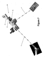
- the femur F is registered.
- the sensor device 2 is rigidly attached to an adjustable cutting block 15.
- a cutting block 15 comprises a base 16 which is rigidly attached to the femur F and a cutting slot 17 which is adjustable relative to the base 16.
- the sensor device 1 is attached to the cutting slot 17.
- the AP direction of the femur is acquired.
- the possibilities for acquiring the AP direction of the femur F are analog to the possibilities described for the tibia with reference to Figure 4 , such that a detailed explanation is omitted.
- the sensor device 1 is used in combination with the pointer 13 to sample the distal end point of the femoral axis.
- the sensor device 1 is detached from the pointer 13 and rigidly fixed in an absolute position.
- the sensor device 1 is rigidly attached to a tripod or an operation room table, in particular to a rail of the table.
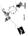
- the femur F is pivoted about its head. This means that the sensor device 2 moves on a spherical shell centered about the center of the femoral head.
- the CPU 3 of the sensor device 2 determines the relative position of the sensor device 2 by detecting the markers 9 and 14 of the sensor device 1 in analogy to the step described with reference to Figures 5 , 6 and 9 .
- this center which is the center of the femoral head
- the femur F is registered in a reference system of the sensor device 2, which is in a fixed relation to a reference system of the cutting slot 17.
- the first sensor device 1 acts as a marker device and the second sensor device 2 acts as a marker device detector.
- the function of a sensor device 1 or 2 that is whether a sensor device acts as a marker device or a marker detector device, is selected by a CPU 3 based on the currently performed workflow step.
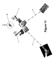
- the first sensor device 1 is re-attached to the cutting slot 12 of the cutting block 10 in the same relative position to the cutting slot 12 as in the workflow steps explained with reference to Figures 3 to 6 .
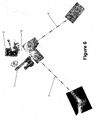
- a measurement of the relative position between the two sensor devices 1 and 2 is performed, including the step of exchanging sensor data and using a reference.
- Exchanging means that at least one of the sensor devices transmits its sensor data, like the orientation data acquired by its gyroscope 5, to the other sensor device using the Bluetooth transceivers 8.
- both sensor devices 1 and 2 exchange their respective orientation data, such that the CPUs 3 of both sensor devices 1 and 2 know the sensor data, like the orientation data, of both sensor devices.
- the gravity field of the earth acts as a reference for the synchronization.
- a reference object 18 is used as a reference.
- the reference object 18 is imaged by at least one camera 6 or 7 of each sensor device 1 and 2.
- the relative position of the reference object 18 relative to the sensor devices 1 and 2 is calculated by the respective CPU 3.
- the position data representing the relative position of the reference object 18 to a sensor device is then transmitted to the other sensor device using the Bluetooth transceivers 7.
- the position information of (just) one sensor device can be transmitted to the other sensor device, or each sensor device can receive the position data from the other sensor device.
- the sensor devices 1 or 2 knows the relative position, this means at least the relative orientation in three-rotational dimensions, of the other sensor device in its own reference system.
- the relative spatial location is not needed in the present workflow, but may also be determined. Since the tibia T and the femur F are registered, the sensor device thus also knows the relative position of the femur F and the tibia T.
- the registration data representing the relation of the bone and the sensor device is also transmitted to the other sensor device. This, again, is performed either in one direction only or both sensor devices transmit the registration data.
- This approach for determining the relative position between the two sensor devices can also be used if one of the sensor devices is used as a marker device detector, such as in the workflow step shown in Figures 5 and 6 , either replacing or supplementing the use of the markers.
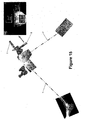
- the tibia T is moved relative to the femur F using the knee joint.
- a measurement of the relative positions between the sensor devices 1 and 2 is performed in a plurality of positions.
- the sensor devices 1 and 2 exchange their orientation data and/or the position data of the reference object 18 such that at least one of the CPUs 3 can calculate the relative position of the sensor devices 1 and 2, and therefore of the femur F and the tibia T.
- the range of motion of the knee joint can be determined. From the relative position, also the varus or valgus angle can be determined. The values of the range of motion as well as the varus/valgus value may be shown on the display 4 of a sensor device, such as depicted in the screenshots in the upper left of Figure 12 .
- Figures 13 to 16 show steps of a second medical workflow. These steps require the registration of the tibia T and the femur F as explained above with reference to Figures 4 to 6 and 8 to 10 , with the same preconditions that an adjustable cutting block 10 is attached to the tibia T and an adjustable cutting block 15 is attached to the femur F.
- the positional relation between the sensor device 1 and the cutting slot 12 is known, as is the positional relation between the sensor device 2 and the cutting slot 17.
- the sensor device 1 is rigidly attached to the cutting slot 12 and the sensor device 2 is rigidly attached to the base 11 of the cutting block 10.
- the current adjustment of the cutting slot 12 relative to the tibia T can be shown on the display 4 of any of the sensor devices as indicated in the screenshot shown in the upper left of Figure 13 .
- a first measurement of the relative position between the sensor devices 1 and 2 is then performed as explained above with reference to Figure 11 . If the cutting block 10 is then adjusted, the relative position between the sensor devices 1 and 2 changes.
- the cutting slot 12 can be adjusted to a desired setting. For example, one of the sensor devices 1 and 2 can output indication information if the current adjustment of the cutting slot 12 relative to the tibia T equals the desired setting. This indication information can be of optical, acoustical or tactile nature.
- the adjustment of the cutting block 10 is tracked using the sensor device 2 as a reference. If the sensor device 1 would use gravity as a reference, then any movement of the tibia T would impair the adjustment of the cutting slot 12. This is overcome by using the sensor device 2, which is rigidly attached to the tibia T via the base 11 of the cutting block 10, as a reference and performing measurements of the relative position by exchanging the orientation data and/or position data.
- the cutting block 15 attached to the femur F is adjusted in analogy to the adjustment process of the cutting block 10 attached to the tibia T as described with reference to Figure 13 .
- the sensor device 1 is rigidly attached to the base 16 and the sensor device 2 is rigidly attached to the cutting slot 17 of the cutting block 15.
- a defined surface of the sensor device 1 is laid onto the cut surface of the femur F.
- the cutting surface can be verified in analogy to the process described with reference to Figure 14 .
- the actual position of the cut surface can be saved for documentation purposes by clicking on the disc symbol of the screenshot shown in the upper left of Figure 16 .
- the desired setting of the cutting slot 12 or 17, respectively can be calculated automatically based on a 3D image dataset representing a 3D image of the tibia or femur, respectively.
- the varus/valgus value and/or the range of motion acquired in the workflow step described with reference to Figure 12 can be used for determining the desired setting.
- the next step of the workflow is begun once the completion of the previous step is automatically detected or manually inputted. So the completion is typically known only to the sensor device which determines the completion. Thus, this sensor device preferably notifies to the other sensor device(s) of the tracking system that the next step is to be performed. This may result in one or more of the sensor devices to change its function from being a marker device to being a marker detection device or vice versa. In addition, a sensor device may display on its display 4 some guidance information on what to do in the next workflow step, thus leading the operator of the tracking system through the workflow.
- a sensor device 1, 2 may further comprise an acceleration sensor (not shown).
- an acceleration sensor not shown
- This information may also be exchanged between the sensor devices and used for calculating the relative position between the sensor devices.
- the sensor data provided by a single sensor device is not sufficient for determining all parameters for all desired dimensions of the relative position.
- the sensor data of a single sensor device is not sufficient to determine the desired number of parameters of the relative position.
- the sensor data of a single sensor device describe insufficient information on the relative position.
- the number of parameters which can be determined from the sensor data of a single sensor device might be less than the desired number of parameters, or the determination of a parameter might require more than the information given by the sensor data of a single sensor device.
- the available information also referred to as sufficient information
- the available information is more than sufficient, such that the information is overdetermined.
- the sensor data is also understood as representing sufficient information. This can be used for increasing the quality of the determined relative position.
Landscapes
- Engineering & Computer Science (AREA)
- Health & Medical Sciences (AREA)
- Surgery (AREA)
- Life Sciences & Earth Sciences (AREA)
- Animal Behavior & Ethology (AREA)
- Veterinary Medicine (AREA)
- Biomedical Technology (AREA)
- Heart & Thoracic Surgery (AREA)
- Medical Informatics (AREA)
- Molecular Biology (AREA)
- Nuclear Medicine, Radiotherapy & Molecular Imaging (AREA)
- General Health & Medical Sciences (AREA)
- Public Health (AREA)
- Robotics (AREA)
- Human Computer Interaction (AREA)
- Physics & Mathematics (AREA)
- General Physics & Mathematics (AREA)
- Multimedia (AREA)
- Theoretical Computer Science (AREA)
- Measurement Of The Respiration, Hearing Ability, Form, And Blood Characteristics Of Living Organisms (AREA)
- Ultra Sonic Daignosis Equipment (AREA)
Claims (14)
- Ein medizinisches Trackingsystem enthaltend mindestens eine Markereinrichtung (1, 2), die in einer festen Position relativ zu einem Zielobjekt (10, 13, 15) positioniert werden kann, die Sensoreinrichtung (1, 2) enthaltend eine Markereinrichtung (9, 14) und einen Markereinrichtungs-Detektor (6, 7), wobei der Markereinrichtungs-Detektor (6, 7) dazu in der Lage ist, Informationen zu gewinnen zum Ermitteln einer Relativposition zwischen dem Markereinrichtungs-Detektor (6, 7) und einer anderen Markereinrichtung (9, 14), das System weiter enthaltend eine Steuereinheit (3), die dazu eingerichtet ist, einen medizinischen Navigations-Workflow abzuarbeiten und die Funktion der Sensoreinrichtung (1, 2) auszuwählen als in einem Schritt des medizinischen Navigations-Workflows entweder agierend als ein Markereinrichtungs-Detektor oder als eine Markereinrichtung, dadurch gekennzeichnet, dass
die Markereinrichtung (9, 14) eine optische Markereinrichtung ist und der Markereinrichtungs-Detektor (6, 7) eine Standbild- oder Videokamera ist. - Das Trackingsystem nach Anspruch 1, wobei die Sensoreinrichtung (1, 2) eine Anzeige (4) enthält zum Anzeigen zumindest eines Teils (14) der Markereinrichtung.
- Das Trackingsystem nach Anspruch 1, wobei die optische Markereinrichtung (9, 14) eine Vielzahl von Vierecken (9) in einer bekannten Konfiguration enthält.
- Das Trackingsystem nach einem der Ansprüche 1 bis 3, wobei das Trackingsystem mindestens zwei Sensoreinrichtungen (1, 2) enthält, wobei, in einem bestimmten Schritt des medizinischen Navigationsworkflows, eine Sensoreinrichtung (1, 2) als eine Markereinrichtung (9, 14) agiert und eine andere Sensoreinrichtung (1, 2) als ein Markereinrichtungs-Detektor (6, 7) agiert.
- Das Trackingsystem nach Anspruch 4, wobei eine der Sensoreinrichtungen (1, 2) in einer festen Position relativ zu einem Zielobjekt (10, 15, F, T) positioniert ist und eine andere Sensoreinrichtung als ein Pointer (13) agiert.
- Das Trackingsystem nach Anspruch 4 oder 5, wobei die als eine Markereinrichtung agierende Sensoreinrichtung die Ausgangsdaten ihres Markereinrichtungs-Detektors, eines Orientierungssensors (5) oder eines Beschleunigungssensors als Sensordaten an die Steuereinheit (3) überträgt, die als eine Marker-Detektionseinrichtung agierende Sensoreinrichtung (1, 2) die Ausgangsdaten ihrer Marker-Detektionseinrichtung (6, 7) als Sensordaten an die Steuereinheit (3) überträgt und die Steuereinheit (3) dazu eingerichtet ist, die Sensordaten der Sensoreinrichtungen (1, 2) zu empfangen und zu kombinieren, um eine Relativposition zwischen zwei Sensoreinrichtungen (1, 2) zu ermitteln.
- Das Trackingsystem nach einem der Ansprüche 1 bis 6, wobei eine Sensoreinrichtung (1,2) weiter einen Orientierungssensor (5) enthält.
- Ein Verfahren des medizinischen Trackens zum Untertützen eines medizinischen Navigations-Workflows, enthaltend die Schritte des Verwendens einer Sensoreinrichtung (1, 2) enthaltend eine optische Markereinrichtung (9, 14) und einen Markereinrichtungs-Detektor (6, 7), der eine Standbild- oder Videokamera ist, als einen Markereinrichtungs-Detektor in einem Schritt des medizinischen Navigations-Workflows, um Informationen zum Ermitteln der Position einer optischen Markereinrichtung (9, 14) zu gewinnen, und des Verwendens derselben Sensoreinrichtung (1, 2) als eine optische Markereinrichtung in einem anderen Schritt des medizinischen Navigations-Workflows.
- Das Verfahren nach Anspruch 8, wobei mindestens zwei Sensoreinrichtungen (1, 2) verwendet werden, wobei eine der Sensoreinrichtungen (1, 2) als eine optische Markereinrichtung eines Pointers (13) zum Zeigen auf Abtastpunkte agiert und eine andere der Sensoreinrichtungen (1, 2), positioniert in einer festen Position relativ zu einem Zielobjekt (10, 15, F, T), als ein Markereinrichtungs-Detektor zum Gewinnen von Informationen zum Ermitteln der Position der optischen Markereinrichtung (9, 14) agiert.
- Das Verfahren nach Anspruch 9, weiter enthaltend den Schritt des Registrierens des Zielobjektes (10, 15, F, T) durch das Abtasten einer Vielzahl von Abtastpunkten.
- Das Verfahren nach Anspruch 9 oder 10, wobei die Sensoreinrichtung (1, 2), die als eine optische Markereinrichtung agiert, und die Sensoreinrichtung (1, 2), die als ein Markereinrichtungs-Detektor agiert, beide einen Orientierungssensor (5) enthalten und die Orientierungssensor-Daten verwendet werden, wenn die Position einer optischen Markereinrichtung detektiert wird.
- Das Verfahren nach einem der Ansprüche 8 bis 11, weiter aufweisend die Schritte des- Ermittelns von Sensordaten enthaltend zumindest eines aus Orientierungsdaten, Positionsdaten und Beschleunigungsdaten mit zwei oder mehr der Sensoreinrichtungen (1, 2),- Übertragens der Sensordaten an eine Steuereinheit (3) und- Ermittelns der Relativposition zwischen zwei Sensoreinrichtungen (1, 2) durch die Steuereinheit (3) durch das Kombinieren der Sensordaten.
- Das Verfahren nach einem der Ansprüche 8 bis 12, wobei die Sensoreinrichtung (1, 2) weiter eine Anzeigeeinrichtung (4) enthält und in einer festen Position relativ zu einem Knochen (F, T) positioniert ist, wobei das von der Standbild- oder Videokamera (6, 7) aufgenommene Bild auf der Anzeigeeinrichtung (4) angezeigt wird und eine charakteristische Eigenschaft des Knochens (F, T) eingegeben werden kann basierend auf dem Kamerabild auf der Anzeigeeinrichtung (4).
- Ein Computerprogramm, das, wenn es auf einem Computer (3) läuft oder in einen Computer geladen ist, den Computer dazu veranlasst, das Verfahren wie in einem der Ansprüche 8 bis 13 beansprucht auszuführen, und/oder ein Programmspeichermedium, auf dem das Programm gespeichert ist (insbesondere in nicht-vergänglicher Form), und/oder ein Computer, auf dem das Programm läuft oder in dessen Speicher das Programm geladen ist.
Applications Claiming Priority (1)
| Application Number | Priority Date | Filing Date | Title |
|---|---|---|---|
| PCT/EP2011/067935 WO2013053397A1 (en) | 2011-10-13 | 2011-10-13 | Medical tracking system comprising multi-functional sensor device |
Publications (2)
| Publication Number | Publication Date |
|---|---|
| EP2765946A1 EP2765946A1 (de) | 2014-08-20 |
| EP2765946B1 true EP2765946B1 (de) | 2015-08-12 |
Family
ID=44800046
Family Applications (1)
| Application Number | Title | Priority Date | Filing Date |
|---|---|---|---|
| EP11769880.3A Active EP2765946B1 (de) | 2011-10-13 | 2011-10-13 | Medizinisches verfolgungssystem mit einer multifunktionellen sensorvorrichtung |
Country Status (3)
| Country | Link |
|---|---|
| US (2) | US10157310B2 (de) |
| EP (1) | EP2765946B1 (de) |
| WO (1) | WO2013053397A1 (de) |
Cited By (1)
| Publication number | Priority date | Publication date | Assignee | Title |
|---|---|---|---|---|
| US10653495B2 (en) | 2016-09-09 | 2020-05-19 | Mobius Imaging Llc | Methods and systems for display of patient data in computer-assisted surgery |
Families Citing this family (19)
| Publication number | Priority date | Publication date | Assignee | Title |
|---|---|---|---|---|
| WO2013053397A1 (en) | 2011-10-13 | 2013-04-18 | Brainlab Ag | Medical tracking system comprising multi-functional sensor device |
| WO2013053398A1 (en) * | 2011-10-13 | 2013-04-18 | Brainlab | Medical tracking system comprising two or more communicating sensor devices |
| US9987093B2 (en) | 2013-07-08 | 2018-06-05 | Brainlab Ag | Single-marker navigation |
| CN105682612B (zh) | 2013-10-15 | 2019-01-04 | 艾克斯潘多索公司 | 用于关节成形术的驱动定位装置及其使用方法 |
| KR101645392B1 (ko) | 2014-08-13 | 2016-08-02 | 주식회사 고영테크놀러지 | 트랙킹 시스템 및 이를 이용한 트랙킹 방법 |
| US20160128783A1 (en) * | 2014-10-29 | 2016-05-12 | Intellijoint Surgical Inc. | Surgical navigation system with one or more body borne components and method therefor |
| WO2016139638A1 (en) * | 2015-03-05 | 2016-09-09 | Atracsys Sàrl | Redundant reciprocal tracking system |
| JP6921754B2 (ja) * | 2015-03-24 | 2021-08-18 | エクスパンドーソ,インコーポレイテッド | 関節形成術用バランシング装置および使用法 |
| CN116650106A (zh) | 2016-03-14 | 2023-08-29 | 穆罕默德·R·马赫福兹 | 用于无线超声跟踪和通信的超宽带定位 |
| US10861604B2 (en) * | 2016-05-05 | 2020-12-08 | Advinow, Inc. | Systems and methods for automated medical diagnostics |
| CN111417352B (zh) | 2016-10-21 | 2024-05-24 | 莫比乌斯成像公司 | 用于设定图像引导式外科手术的轨迹和目标位置的方法和系统 |
| CA3073335A1 (en) * | 2017-08-22 | 2019-02-28 | William L WALTER | Scanning apparatus for scanning an anatomical region |
| WO2021076909A1 (en) * | 2019-10-18 | 2021-04-22 | Practical Navigation Llc | Surgical navigation system |
| CA3164828C (en) | 2021-06-24 | 2025-07-08 | Northern Digital Inc. | RETROREFLECTIVE TARGET DISC |
| CN113792595A (zh) * | 2021-08-10 | 2021-12-14 | 北京爱笔科技有限公司 | 目标行为检测方法、装置、计算机设备和存储介质 |
| US12295797B2 (en) | 2022-02-03 | 2025-05-13 | Medtronic Navigation, Inc. | Systems, methods, and devices for providing an augmented display |
| US12249099B2 (en) | 2022-02-03 | 2025-03-11 | Medtronic Navigation, Inc. | Systems, methods, and devices for reconstructing a three-dimensional representation |
| US12004821B2 (en) | 2022-02-03 | 2024-06-11 | Medtronic Navigation, Inc. | Systems, methods, and devices for generating a hybrid image |
| WO2024125773A1 (en) * | 2022-12-13 | 2024-06-20 | Stryker European Operations Limited | Wide angle navigation system |
Family Cites Families (22)
| Publication number | Priority date | Publication date | Assignee | Title |
|---|---|---|---|---|
| US6119033A (en) | 1997-03-04 | 2000-09-12 | Biotrack, Inc. | Method of monitoring a location of an area of interest within a patient during a medical procedure |
| AU3197699A (en) * | 1998-03-30 | 1999-10-18 | Biosense, Inc. | Three-axis coil sensor |
| US20010034530A1 (en) | 2000-01-27 | 2001-10-25 | Malackowski Donald W. | Surgery system |
| WO2004091419A2 (en) | 2003-04-08 | 2004-10-28 | Wasielewski Ray C | Use of micro-and miniature position sensing devices for use in tka and tha |
| JP4476744B2 (ja) | 2003-09-02 | 2010-06-09 | 富士フイルム株式会社 | 撮像システム、及びプログラム |
| CA2553842A1 (en) * | 2004-01-22 | 2005-08-04 | Smith & Nephew, Inc. | Methods, systems, and apparatuses for providing patient-mounted surgical navigational sensors |
| AU2005237479B8 (en) | 2004-04-21 | 2011-09-29 | Smith & Nephew, Inc. | Computer-aided methods for shoulder arthroplasty |
| US20070078678A1 (en) * | 2005-09-30 | 2007-04-05 | Disilvestro Mark R | System and method for performing a computer assisted orthopaedic surgical procedure |
| US8862200B2 (en) | 2005-12-30 | 2014-10-14 | DePuy Synthes Products, LLC | Method for determining a position of a magnetic source |
| US7715606B2 (en) * | 2006-10-18 | 2010-05-11 | Varian Medical Systems, Inc. | Marker system and method of using the same |
| DE502006003472D1 (de) * | 2006-10-20 | 2009-05-28 | Brainlab Ag | Markernavigationsvorrichtung insbesondere für medizinische Zwecke |
| US20080180537A1 (en) * | 2006-11-14 | 2008-07-31 | Uri Weinberg | Camera system and methods |
| KR101187909B1 (ko) | 2007-10-04 | 2012-10-05 | 삼성테크윈 주식회사 | 감시 카메라 시스템 |
| EP2455038B1 (de) * | 2008-10-21 | 2015-04-01 | Brainlab AG | Integration von chirurgischem Instrument und Anzeigevorrichtung zur Unterstützung der bildgeführten Chirurgie |
| DE102008055918A1 (de) * | 2008-11-05 | 2010-05-06 | Siemens Aktiengesellschaft | Verfahren zum Betreiben eines medizinischen Navigationssystems und medizinisches Navigationssystem |
| WO2011047467A1 (en) * | 2009-10-20 | 2011-04-28 | Imris Inc. | Imaging system using markers |
| AU2011341678B2 (en) | 2010-01-21 | 2014-12-11 | OrthAlign, Inc. | Systems and methods for joint replacement |
| JP2013524952A (ja) * | 2010-04-22 | 2013-06-20 | ブルー ベルト テクノロジーズ,エル エル シー | 再構成可能なナビゲートされる外科用器具のトラッキング装置 |
| US20120046536A1 (en) * | 2010-08-20 | 2012-02-23 | Manhattan Technologies, Llc | Surgical Instrument Navigation Systems and Methods |
| EP2720634B1 (de) | 2011-06-15 | 2023-05-03 | Brainlab AG | Vorrichtung zur bestimmung der mechanischen achse eines knochens |
| WO2013053397A1 (en) | 2011-10-13 | 2013-04-18 | Brainlab Ag | Medical tracking system comprising multi-functional sensor device |
| WO2013053398A1 (en) | 2011-10-13 | 2013-04-18 | Brainlab | Medical tracking system comprising two or more communicating sensor devices |
-
2011
- 2011-10-13 WO PCT/EP2011/067935 patent/WO2013053397A1/en not_active Ceased
- 2011-10-13 US US14/349,466 patent/US10157310B2/en active Active
- 2011-10-13 EP EP11769880.3A patent/EP2765946B1/de active Active
-
2018
- 2018-11-09 US US16/185,648 patent/US10762341B2/en active Active
Cited By (4)
| Publication number | Priority date | Publication date | Assignee | Title |
|---|---|---|---|---|
| US10653495B2 (en) | 2016-09-09 | 2020-05-19 | Mobius Imaging Llc | Methods and systems for display of patient data in computer-assisted surgery |
| US11141237B2 (en) | 2016-09-09 | 2021-10-12 | Mobius Imaging Llc | Methods and systems for display of patient data in computer-assisted surgery |
| US11737850B2 (en) | 2016-09-09 | 2023-08-29 | Mobius Imaging Llc | Methods and systems for display of patient data in computer-assisted surgery |
| US12167940B2 (en) | 2016-09-09 | 2024-12-17 | Mobius Imaging, Llc | Methods and systems for display of patient data in computer-assisted surgery |
Also Published As
| Publication number | Publication date |
|---|---|
| WO2013053397A1 (en) | 2013-04-18 |
| US20140247336A1 (en) | 2014-09-04 |
| US10762341B2 (en) | 2020-09-01 |
| US20190080161A1 (en) | 2019-03-14 |
| EP2765946A1 (de) | 2014-08-20 |
| US10157310B2 (en) | 2018-12-18 |
Similar Documents
| Publication | Publication Date | Title |
|---|---|---|
| US10762341B2 (en) | Medical tracking system comprising multi-functional sensor device | |
| US11076133B2 (en) | Medical tracking system comprising two or more communicating sensor devices | |
| US11065066B2 (en) | Method for enabling medical navigation with minimised invasiveness | |
| US10342619B2 (en) | Method and device for determining the mechanical axis of a bone | |
| US20200305897A1 (en) | Systems and methods for placement of surgical instrumentation | |
| US20190090955A1 (en) | Systems and methods for position and orientation tracking of anatomy and surgical instruments | |
| US10244967B2 (en) | Method and apparatus for determining differences in geometry of subject element using landmarks | |
| EP3386389B1 (de) | Bestimmung des rotationszentrums eines knochens | |
| US8469965B2 (en) | Tool for detecting planes of a bone and assigned data processing method | |
| US10624764B2 (en) | System and method for the registration of an anatomical feature | |
| US12406396B2 (en) | Microscope camera calibration |
Legal Events
| Date | Code | Title | Description |
|---|---|---|---|
| PUAI | Public reference made under article 153(3) epc to a published international application that has entered the european phase |
Free format text: ORIGINAL CODE: 0009012 |
|
| 17P | Request for examination filed |
Effective date: 20140225 |
|
| AK | Designated contracting states |
Kind code of ref document: A1 Designated state(s): AL AT BE BG CH CY CZ DE DK EE ES FI FR GB GR HR HU IE IS IT LI LT LU LV MC MK MT NL NO PL PT RO RS SE SI SK SM TR |
|
| DAX | Request for extension of the european patent (deleted) | ||
| 17Q | First examination report despatched |
Effective date: 20150210 |
|
| GRAP | Despatch of communication of intention to grant a patent |
Free format text: ORIGINAL CODE: EPIDOSNIGR1 |
|
| INTG | Intention to grant announced |
Effective date: 20150420 |
|
| GRAS | Grant fee paid |
Free format text: ORIGINAL CODE: EPIDOSNIGR3 |
|
| GRAA | (expected) grant |
Free format text: ORIGINAL CODE: 0009210 |
|
| AK | Designated contracting states |
Kind code of ref document: B1 Designated state(s): AL AT BE BG CH CY CZ DE DK EE ES FI FR GB GR HR HU IE IS IT LI LT LU LV MC MK MT NL NO PL PT RO RS SE SI SK SM TR |
|
| REG | Reference to a national code |
Ref country code: GB Ref legal event code: FG4D |
|
| REG | Reference to a national code |
Ref country code: CH Ref legal event code: EP |
|
| REG | Reference to a national code |
Ref country code: AT Ref legal event code: REF Ref document number: 741421 Country of ref document: AT Kind code of ref document: T Effective date: 20150815 |
|
| REG | Reference to a national code |
Ref country code: IE Ref legal event code: FG4D |
|
| REG | Reference to a national code |
Ref country code: DE Ref legal event code: R096 Ref document number: 602011018734 Country of ref document: DE |
|
| REG | Reference to a national code |
Ref country code: FR Ref legal event code: PLFP Year of fee payment: 5 |
|
| REG | Reference to a national code |
Ref country code: LT Ref legal event code: MG4D |
|
| REG | Reference to a national code |
Ref country code: AT Ref legal event code: MK05 Ref document number: 741421 Country of ref document: AT Kind code of ref document: T Effective date: 20150812 |
|
| REG | Reference to a national code |
Ref country code: NL Ref legal event code: MP Effective date: 20150812 |
|
| PG25 | Lapsed in a contracting state [announced via postgrant information from national office to epo] |
Ref country code: NO Free format text: LAPSE BECAUSE OF FAILURE TO SUBMIT A TRANSLATION OF THE DESCRIPTION OR TO PAY THE FEE WITHIN THE PRESCRIBED TIME-LIMIT Effective date: 20151112 Ref country code: LT Free format text: LAPSE BECAUSE OF FAILURE TO SUBMIT A TRANSLATION OF THE DESCRIPTION OR TO PAY THE FEE WITHIN THE PRESCRIBED TIME-LIMIT Effective date: 20150812 Ref country code: FI Free format text: LAPSE BECAUSE OF FAILURE TO SUBMIT A TRANSLATION OF THE DESCRIPTION OR TO PAY THE FEE WITHIN THE PRESCRIBED TIME-LIMIT Effective date: 20150812 Ref country code: LV Free format text: LAPSE BECAUSE OF FAILURE TO SUBMIT A TRANSLATION OF THE DESCRIPTION OR TO PAY THE FEE WITHIN THE PRESCRIBED TIME-LIMIT Effective date: 20150812 Ref country code: GR Free format text: LAPSE BECAUSE OF FAILURE TO SUBMIT A TRANSLATION OF THE DESCRIPTION OR TO PAY THE FEE WITHIN THE PRESCRIBED TIME-LIMIT Effective date: 20151113 |
|
| PG25 | Lapsed in a contracting state [announced via postgrant information from national office to epo] |
Ref country code: HR Free format text: LAPSE BECAUSE OF FAILURE TO SUBMIT A TRANSLATION OF THE DESCRIPTION OR TO PAY THE FEE WITHIN THE PRESCRIBED TIME-LIMIT Effective date: 20150812 Ref country code: SE Free format text: LAPSE BECAUSE OF FAILURE TO SUBMIT A TRANSLATION OF THE DESCRIPTION OR TO PAY THE FEE WITHIN THE PRESCRIBED TIME-LIMIT Effective date: 20150812 Ref country code: AT Free format text: LAPSE BECAUSE OF FAILURE TO SUBMIT A TRANSLATION OF THE DESCRIPTION OR TO PAY THE FEE WITHIN THE PRESCRIBED TIME-LIMIT Effective date: 20150812 Ref country code: PT Free format text: LAPSE BECAUSE OF FAILURE TO SUBMIT A TRANSLATION OF THE DESCRIPTION OR TO PAY THE FEE WITHIN THE PRESCRIBED TIME-LIMIT Effective date: 20151214 Ref country code: ES Free format text: LAPSE BECAUSE OF FAILURE TO SUBMIT A TRANSLATION OF THE DESCRIPTION OR TO PAY THE FEE WITHIN THE PRESCRIBED TIME-LIMIT Effective date: 20150812 Ref country code: IS Free format text: LAPSE BECAUSE OF FAILURE TO SUBMIT A TRANSLATION OF THE DESCRIPTION OR TO PAY THE FEE WITHIN THE PRESCRIBED TIME-LIMIT Effective date: 20151212 Ref country code: RS Free format text: LAPSE BECAUSE OF FAILURE TO SUBMIT A TRANSLATION OF THE DESCRIPTION OR TO PAY THE FEE WITHIN THE PRESCRIBED TIME-LIMIT Effective date: 20150812 Ref country code: PL Free format text: LAPSE BECAUSE OF FAILURE TO SUBMIT A TRANSLATION OF THE DESCRIPTION OR TO PAY THE FEE WITHIN THE PRESCRIBED TIME-LIMIT Effective date: 20150812 |
|
| PG25 | Lapsed in a contracting state [announced via postgrant information from national office to epo] |
Ref country code: NL Free format text: LAPSE BECAUSE OF FAILURE TO SUBMIT A TRANSLATION OF THE DESCRIPTION OR TO PAY THE FEE WITHIN THE PRESCRIBED TIME-LIMIT Effective date: 20150812 |
|
| PG25 | Lapsed in a contracting state [announced via postgrant information from national office to epo] |
Ref country code: IT Free format text: LAPSE BECAUSE OF FAILURE TO SUBMIT A TRANSLATION OF THE DESCRIPTION OR TO PAY THE FEE WITHIN THE PRESCRIBED TIME-LIMIT Effective date: 20150812 Ref country code: EE Free format text: LAPSE BECAUSE OF FAILURE TO SUBMIT A TRANSLATION OF THE DESCRIPTION OR TO PAY THE FEE WITHIN THE PRESCRIBED TIME-LIMIT Effective date: 20150812 Ref country code: SK Free format text: LAPSE BECAUSE OF FAILURE TO SUBMIT A TRANSLATION OF THE DESCRIPTION OR TO PAY THE FEE WITHIN THE PRESCRIBED TIME-LIMIT Effective date: 20150812 Ref country code: DK Free format text: LAPSE BECAUSE OF FAILURE TO SUBMIT A TRANSLATION OF THE DESCRIPTION OR TO PAY THE FEE WITHIN THE PRESCRIBED TIME-LIMIT Effective date: 20150812 Ref country code: CZ Free format text: LAPSE BECAUSE OF FAILURE TO SUBMIT A TRANSLATION OF THE DESCRIPTION OR TO PAY THE FEE WITHIN THE PRESCRIBED TIME-LIMIT Effective date: 20150812 |
|
| REG | Reference to a national code |
Ref country code: DE Ref legal event code: R097 Ref document number: 602011018734 Country of ref document: DE |
|
| PG25 | Lapsed in a contracting state [announced via postgrant information from national office to epo] |
Ref country code: RO Free format text: LAPSE BECAUSE OF FAILURE TO SUBMIT A TRANSLATION OF THE DESCRIPTION OR TO PAY THE FEE WITHIN THE PRESCRIBED TIME-LIMIT Effective date: 20150812 Ref country code: LU Free format text: LAPSE BECAUSE OF FAILURE TO SUBMIT A TRANSLATION OF THE DESCRIPTION OR TO PAY THE FEE WITHIN THE PRESCRIBED TIME-LIMIT Effective date: 20151013 |
|
| REG | Reference to a national code |
Ref country code: CH Ref legal event code: PL |
|
| PLBE | No opposition filed within time limit |
Free format text: ORIGINAL CODE: 0009261 |
|
| STAA | Information on the status of an ep patent application or granted ep patent |
Free format text: STATUS: NO OPPOSITION FILED WITHIN TIME LIMIT |
|
| PG25 | Lapsed in a contracting state [announced via postgrant information from national office to epo] |
Ref country code: MC Free format text: LAPSE BECAUSE OF FAILURE TO SUBMIT A TRANSLATION OF THE DESCRIPTION OR TO PAY THE FEE WITHIN THE PRESCRIBED TIME-LIMIT Effective date: 20150812 |
|
| 26N | No opposition filed |
Effective date: 20160513 |
|
| REG | Reference to a national code |
Ref country code: IE Ref legal event code: MM4A |
|
| PG25 | Lapsed in a contracting state [announced via postgrant information from national office to epo] |
Ref country code: CH Free format text: LAPSE BECAUSE OF NON-PAYMENT OF DUE FEES Effective date: 20151031 Ref country code: LI Free format text: LAPSE BECAUSE OF NON-PAYMENT OF DUE FEES Effective date: 20151031 |
|
| PG25 | Lapsed in a contracting state [announced via postgrant information from national office to epo] |
Ref country code: SI Free format text: LAPSE BECAUSE OF FAILURE TO SUBMIT A TRANSLATION OF THE DESCRIPTION OR TO PAY THE FEE WITHIN THE PRESCRIBED TIME-LIMIT Effective date: 20150812 |
|
| REG | Reference to a national code |
Ref country code: FR Ref legal event code: PLFP Year of fee payment: 6 |
|
| PG25 | Lapsed in a contracting state [announced via postgrant information from national office to epo] |
Ref country code: IE Free format text: LAPSE BECAUSE OF NON-PAYMENT OF DUE FEES Effective date: 20151013 |
|
| PG25 | Lapsed in a contracting state [announced via postgrant information from national office to epo] |
Ref country code: BE Free format text: LAPSE BECAUSE OF FAILURE TO SUBMIT A TRANSLATION OF THE DESCRIPTION OR TO PAY THE FEE WITHIN THE PRESCRIBED TIME-LIMIT Effective date: 20150812 |
|
| REG | Reference to a national code |
Ref country code: DE Ref legal event code: R082 Ref document number: 602011018734 Country of ref document: DE Representative=s name: SCHWABE SANDMAIR MARX PATENTANWAELTE RECHTSANW, DE Ref country code: DE Ref legal event code: R081 Ref document number: 602011018734 Country of ref document: DE Owner name: BRAINLAB AG, DE Free format text: FORMER OWNER: BRAINLAB AG, 85622 FELDKIRCHEN, DE Ref country code: DE Ref legal event code: R082 Ref document number: 602011018734 Country of ref document: DE Representative=s name: SSM SANDMAIR PATENTANWAELTE RECHTSANWALT PARTN, DE |
|
| PG25 | Lapsed in a contracting state [announced via postgrant information from national office to epo] |
Ref country code: HU Free format text: LAPSE BECAUSE OF FAILURE TO SUBMIT A TRANSLATION OF THE DESCRIPTION OR TO PAY THE FEE WITHIN THE PRESCRIBED TIME-LIMIT; INVALID AB INITIO Effective date: 20111013 Ref country code: SM Free format text: LAPSE BECAUSE OF FAILURE TO SUBMIT A TRANSLATION OF THE DESCRIPTION OR TO PAY THE FEE WITHIN THE PRESCRIBED TIME-LIMIT Effective date: 20150812 Ref country code: BG Free format text: LAPSE BECAUSE OF FAILURE TO SUBMIT A TRANSLATION OF THE DESCRIPTION OR TO PAY THE FEE WITHIN THE PRESCRIBED TIME-LIMIT Effective date: 20150812 |
|
| PG25 | Lapsed in a contracting state [announced via postgrant information from national office to epo] |
Ref country code: CY Free format text: LAPSE BECAUSE OF FAILURE TO SUBMIT A TRANSLATION OF THE DESCRIPTION OR TO PAY THE FEE WITHIN THE PRESCRIBED TIME-LIMIT Effective date: 20150812 |
|
| REG | Reference to a national code |
Ref country code: FR Ref legal event code: CA Effective date: 20170706 |
|
| PG25 | Lapsed in a contracting state [announced via postgrant information from national office to epo] |
Ref country code: MT Free format text: LAPSE BECAUSE OF FAILURE TO SUBMIT A TRANSLATION OF THE DESCRIPTION OR TO PAY THE FEE WITHIN THE PRESCRIBED TIME-LIMIT Effective date: 20150812 |
|
| REG | Reference to a national code |
Ref country code: FR Ref legal event code: PLFP Year of fee payment: 7 |
|
| PG25 | Lapsed in a contracting state [announced via postgrant information from national office to epo] |
Ref country code: MK Free format text: LAPSE BECAUSE OF FAILURE TO SUBMIT A TRANSLATION OF THE DESCRIPTION OR TO PAY THE FEE WITHIN THE PRESCRIBED TIME-LIMIT Effective date: 20150812 |
|
| REG | Reference to a national code |
Ref country code: FR Ref legal event code: PLFP Year of fee payment: 8 |
|
| PG25 | Lapsed in a contracting state [announced via postgrant information from national office to epo] |
Ref country code: TR Free format text: LAPSE BECAUSE OF FAILURE TO SUBMIT A TRANSLATION OF THE DESCRIPTION OR TO PAY THE FEE WITHIN THE PRESCRIBED TIME-LIMIT Effective date: 20150812 Ref country code: AL Free format text: LAPSE BECAUSE OF FAILURE TO SUBMIT A TRANSLATION OF THE DESCRIPTION OR TO PAY THE FEE WITHIN THE PRESCRIBED TIME-LIMIT Effective date: 20150812 |
|
| P01 | Opt-out of the competence of the unified patent court (upc) registered |
Effective date: 20230510 |
|
| REG | Reference to a national code |
Ref country code: DE Ref legal event code: R081 Ref document number: 602011018734 Country of ref document: DE Owner name: BRAINLAB SE, DE Free format text: FORMER OWNER: BRAINLAB AG, 81829 MUENCHEN, DE |
|
| PGFP | Annual fee paid to national office [announced via postgrant information from national office to epo] |
Ref country code: DE Payment date: 20251021 Year of fee payment: 15 |
|
| PGFP | Annual fee paid to national office [announced via postgrant information from national office to epo] |
Ref country code: GB Payment date: 20251022 Year of fee payment: 15 |
|
| PGFP | Annual fee paid to national office [announced via postgrant information from national office to epo] |
Ref country code: FR Payment date: 20251030 Year of fee payment: 15 |