EP2766529B1 - Front pin lock for a tool attachment device - Google Patents
Front pin lock for a tool attachment device Download PDFInfo
- Publication number
- EP2766529B1 EP2766529B1 EP12835960.1A EP12835960A EP2766529B1 EP 2766529 B1 EP2766529 B1 EP 2766529B1 EP 12835960 A EP12835960 A EP 12835960A EP 2766529 B1 EP2766529 B1 EP 2766529B1
- Authority
- EP
- European Patent Office
- Prior art keywords
- locking
- distance
- arrangement
- segment
- locking arrangement
- Prior art date
- Legal status (The legal status is an assumption and is not a legal conclusion. Google has not performed a legal analysis and makes no representation as to the accuracy of the status listed.)
- Not-in-force
Links
- 230000008878 coupling Effects 0.000 description 7
- 238000010168 coupling process Methods 0.000 description 7
- 238000005859 coupling reaction Methods 0.000 description 7
- 238000003780 insertion Methods 0.000 description 5
- 230000037431 insertion Effects 0.000 description 5
- 239000012530 fluid Substances 0.000 description 2
- 230000004913 activation Effects 0.000 description 1
- 230000006835 compression Effects 0.000 description 1
- 238000007906 compression Methods 0.000 description 1
- 230000008602 contraction Effects 0.000 description 1
- 230000003247 decreasing effect Effects 0.000 description 1
- 206010016256 fatigue Diseases 0.000 description 1
- 230000014509 gene expression Effects 0.000 description 1
- 238000004519 manufacturing process Methods 0.000 description 1
- 238000000034 method Methods 0.000 description 1
- 238000007789 sealing Methods 0.000 description 1
- 239000007787 solid Substances 0.000 description 1
- 239000000725 suspension Substances 0.000 description 1
Images


Classifications
-
- E—FIXED CONSTRUCTIONS
- E02—HYDRAULIC ENGINEERING; FOUNDATIONS; SOIL SHIFTING
- E02F—DREDGING; SOIL-SHIFTING
- E02F3/00—Dredgers; Soil-shifting machines
- E02F3/04—Dredgers; Soil-shifting machines mechanically-driven
- E02F3/28—Dredgers; Soil-shifting machines mechanically-driven with digging tools mounted on a dipper- or bucket-arm, i.e. there is either one arm or a pair of arms, e.g. dippers, buckets
- E02F3/36—Component parts
- E02F3/3604—Devices to connect tools to arms, booms or the like
- E02F3/3609—Devices to connect tools to arms, booms or the like of the quick acting type, e.g. controlled from the operator seat
- E02F3/3627—Devices to connect tools to arms, booms or the like of the quick acting type, e.g. controlled from the operator seat with a hook and a longitudinal locking element
-
- E—FIXED CONSTRUCTIONS
- E02—HYDRAULIC ENGINEERING; FOUNDATIONS; SOIL SHIFTING
- E02F—DREDGING; SOIL-SHIFTING
- E02F3/00—Dredgers; Soil-shifting machines
- E02F3/04—Dredgers; Soil-shifting machines mechanically-driven
- E02F3/28—Dredgers; Soil-shifting machines mechanically-driven with digging tools mounted on a dipper- or bucket-arm, i.e. there is either one arm or a pair of arms, e.g. dippers, buckets
- E02F3/36—Component parts
- E02F3/3604—Devices to connect tools to arms, booms or the like
- E02F3/3609—Devices to connect tools to arms, booms or the like of the quick acting type, e.g. controlled from the operator seat
- E02F3/3618—Devices to connect tools to arms, booms or the like of the quick acting type, e.g. controlled from the operator seat with two separating hooks
-
- E—FIXED CONSTRUCTIONS
- E02—HYDRAULIC ENGINEERING; FOUNDATIONS; SOIL SHIFTING
- E02F—DREDGING; SOIL-SHIFTING
- E02F3/00—Dredgers; Soil-shifting machines
- E02F3/04—Dredgers; Soil-shifting machines mechanically-driven
- E02F3/28—Dredgers; Soil-shifting machines mechanically-driven with digging tools mounted on a dipper- or bucket-arm, i.e. there is either one arm or a pair of arms, e.g. dippers, buckets
- E02F3/36—Component parts
- E02F3/3604—Devices to connect tools to arms, booms or the like
- E02F3/3609—Devices to connect tools to arms, booms or the like of the quick acting type, e.g. controlled from the operator seat
- E02F3/365—Devices to connect tools to arms, booms or the like of the quick acting type, e.g. controlled from the operator seat with redundant latching means, e.g. for safety purposes
-
- E—FIXED CONSTRUCTIONS
- E02—HYDRAULIC ENGINEERING; FOUNDATIONS; SOIL SHIFTING
- E02F—DREDGING; SOIL-SHIFTING
- E02F3/00—Dredgers; Soil-shifting machines
- E02F3/04—Dredgers; Soil-shifting machines mechanically-driven
- E02F3/28—Dredgers; Soil-shifting machines mechanically-driven with digging tools mounted on a dipper- or bucket-arm, i.e. there is either one arm or a pair of arms, e.g. dippers, buckets
- E02F3/36—Component parts
- E02F3/3604—Devices to connect tools to arms, booms or the like
- E02F3/3609—Devices to connect tools to arms, booms or the like of the quick acting type, e.g. controlled from the operator seat
- E02F3/3663—Devices to connect tools to arms, booms or the like of the quick acting type, e.g. controlled from the operator seat hydraulically-operated
-
- E—FIXED CONSTRUCTIONS
- E02—HYDRAULIC ENGINEERING; FOUNDATIONS; SOIL SHIFTING
- E02F—DREDGING; SOIL-SHIFTING
- E02F9/00—Component parts of dredgers or soil-shifting machines, not restricted to one of the kinds covered by groups E02F3/00 - E02F7/00
- E02F9/26—Indicating devices
-
- E—FIXED CONSTRUCTIONS
- E02—HYDRAULIC ENGINEERING; FOUNDATIONS; SOIL SHIFTING
- E02F—DREDGING; SOIL-SHIFTING
- E02F3/00—Dredgers; Soil-shifting machines
- E02F3/04—Dredgers; Soil-shifting machines mechanically-driven
- E02F3/28—Dredgers; Soil-shifting machines mechanically-driven with digging tools mounted on a dipper- or bucket-arm, i.e. there is either one arm or a pair of arms, e.g. dippers, buckets
- E02F3/36—Component parts
- E02F3/3604—Devices to connect tools to arms, booms or the like
- E02F3/3609—Devices to connect tools to arms, booms or the like of the quick acting type, e.g. controlled from the operator seat
- E02F3/3645—Devices to connect tools to arms, booms or the like of the quick acting type, e.g. controlled from the operator seat with auto-engagement means for automatic snap-on of the tool coupler part
-
- Y—GENERAL TAGGING OF NEW TECHNOLOGICAL DEVELOPMENTS; GENERAL TAGGING OF CROSS-SECTIONAL TECHNOLOGIES SPANNING OVER SEVERAL SECTIONS OF THE IPC; TECHNICAL SUBJECTS COVERED BY FORMER USPC CROSS-REFERENCE ART COLLECTIONS [XRACs] AND DIGESTS
- Y10—TECHNICAL SUBJECTS COVERED BY FORMER USPC
- Y10T—TECHNICAL SUBJECTS COVERED BY FORMER US CLASSIFICATION
- Y10T403/00—Joints and connections
- Y10T403/70—Interfitted members
- Y10T403/7075—Interfitted members including discrete retainer
Definitions
- the present invention relates generally to a quick coupler used for attaching a tool to an earth moving vehicle, where the quick coupler comprises a locking device and a front pin locking arrangement.
- quick couplers are used for connecting different tools to an earth moving machine, for example an excavator, backhoe loader or a digger.
- an earth moving machine for example an excavator, backhoe loader or a digger.
- the quick coupling is mounted directly on the excavator art or on a on the arm mounted tilt rotator which allow tool movement in all directions. It can also be integrated in the tilt rotator.
- the quick coupling has in its lower part a locking mechanism adapted to lock the tool, either mechanically or with a hydraulically controlled lock.
- the locking mechanism often comprises a solid grip and a locking wedge or locking pins which locks the tool around parallel axles attached to the attachment bracket.
- Quick couplers can be divided into two groups; universal or dedicated.
- Universal quick couplers are characterized in that the quick coupler is constructed to be able to be used on tools originating from different tool manufactures. Since the tools originate from different tool manufacturers or different excavator models, the distance between the parallel axles can vary and the diameter of the axles can be different. Thus, a universal quick coupler normally fits tools with different distances between the axles and sometimes also fit tools with different axle diameter.
- Dedicated quick couplers are, on the other hand, based on a standard, which result in that the quick coupler only fits if the tool follows the standard from which the quick coupler is constructed. Only the upper part, i.e. the part mounted adjacent the excavator arm, varies while the locking mechanism follows a standard.
- the most common standard for quick couplers on the Nordic market is symmetrical quick couplers, which are based on a gate with two parallel axles.
- a problem with quick couplers of today is that it is a large risk that the driver drops the tool during the connection of the tool to the excavator, since the driver believe that the tool is securely locked with the locking mechanism even though this is not the case.
- the tool is lifted and run the risk of falling out from the front grip of the tool coupler due to gliding of the tool front axle.
- WO2008/051095 A2 discloses a safety lock for one of the attachment pins comprising an hydraulic cylinder. Unlocking and locking of the safety lock occur actively through the cylinder. Just as in the previous mentioned document this solution does not permit locking of the safety lock for a locked position of the locking arrangement.
- EP1318242 B1 discloses a system for making safety locking possible.
- the disadvantage with the system is that safety locking is not possible when the locking arrangement is in a locked position.
- the positioning of the attachment pin in a cut out is not possible when the locking arrangement is locked, only when it is open.
- WO2010/062193A1 discloses a coupling arrangement for attachment of a working tool and a method for unlocking which requires several steps.
- the snap locking of a first attachment pin is possible by a floatingly suspended hydraulic cylinder, i.e. arranged to be able to move up and down in the coupling arrangement.
- the disengagement of the safety lock occurs actively by contraction of the hydraulic cylinder which thus is connected for this purpose.
- the disadvantage with this solution is that the floating suspension of a hydraulic cylinder, i.e. by letting a large number of included components be moveable, increases the risk of fatigue of the parts over time and thereto also the risk of failure in the locking arrangement which is a safety risk.
- WO2005/026454 A1 discloses a safety lock for quick coupling of a tool. Safety locking is however not possible when the locking arrangement is in a locked position, and it requires a 180° rotation for unlocking.
- a locking arrangement having the shape of a, in relation to the quick coupler, laterally extending hydraulically actuated pin, which both see to that the lock remains locked and which, with a colored outer part visible for the driver, indicates that this is the case.
- US5692855A shows a coupling arrangement where a handle visible for the observer is turned together with the locking arrangement and indicates locked and unlocked position, respectively.
- An object of the present invention is to in a robust and safe way lock a quick coupler of an earth moving vehicle, for example an excavator, in a first and preferably a front attachment pin in a tool.
- a further object is to in a simple and clear way indicate when the quick coupler is locked.
- a quick coupler in which the at least one locking piston has an outer end and an inner end whereby the at least one locking segment is arranged in relation to the at least one locking piston so that at least some point in the outer end of the locking piston is located at a first distance from the centre of rotation of the at least one locking segment by an outer position when the at least one locking arrangement is in a locked position, and where at least some point on the outer end of the at least one locking piston is located on a second distance from the centre of rotation of the at least one locking segment by an inner position, when the at least one locking arrangement is in an unlocked position, where the first distance is less than the second distance, where the at least one locking segment has a cam surface, by which the radius from the centre of rotation to the cam surface varies along the circumference of the locking segment, whereby the locking segment has a cam surface section at a corresponding first radius r1 and a second radius r2, whereby the first radius r1 is larger than the second radius r2.
- a quick coupler in which the first radius r1 of the at least one locking segment is larger than the first distance when the locking arrangement is in a locked position and smaller than the second distance when the at least one locking arrangement is in an open position and where the second radius r2 is smaller than the first distance when the at least one locking arrangement is in a locked position and smaller than the second distance when the at least one locking arrangement is in an open position.
- a quick coupler in which a locking plate is arranged to the hydraulic cylinder, whereby the inner end of the at least one locking piston is mechanically disconnected from the locking plate, whereby the inner end of the at least one locking piston is at a third distance from the locking plate, whereby the third distance is null when the at least one locking arrangement is in a locked position.
- a quick coupler in which the first radius r1 of the at least one locking segment is larger than the sum of the second distance and the third distance when the at least one locking arrangement is in a locked position and smaller than the sum of the first and the third distance when the at least one locking arrangement is in an open position and where the second radius r2 is smaller than the sum of the first and the third distance when the at least one locking arrangement is in a locked position and smaller than the sum of the second and the third distance when the at least one locking arrangement is in an open position.
- a quick coupler in which a first attachment pin with a first diameter D is adapted to be inserted through an opening to rest in a horizontal first cut-out, whereby the second radius r2 is defined by having a corresponding cam surface section located on a shortest distance a to the opposite wall of the opening when the at least one locking arrangement is located in a locked position and the first attachment pin is inserted to rest in the horizontal first cut-out and the at least one locking segment is limiting the first cut-out, whereby the first radius r1 is defined as having a cam surface section which at this position touches a part of the outer ends of the at least one locking piston, whereby the first radius r1 is of such a length that the first diameter D is larger than the shortest distance a to the opposite wall of the opening when the at least one locking arrangement is located in a locked position and the first attachment pin is inserted to rest in the horizontal cut-out and the at least one locking segment delimits the first cut-out.
- a quick coupler in which the at least one locking piston is adapted to be moved essentially linearly by the at least one actuator in at least one direction essentially parallel to the extension direction of the first cut-out.
- a quick coupler in which the at least one locking arrangement and the at least one locking piston are arranged to be moved essentially simultaneously in opposite directions.
- a quick coupler in which a spring is arranged in connection to the at least one locking segment with the purpose of biasing the at least one locking segment in a first direction of rotation.
- a quick coupler which comprises a lock indication device which visually indicates if the locking arrangement is in an open or closed position, in which the at least one actuator is arranged between the at least one locking arrangement and the at least one lock indication device and is arranged to move both the at least one locking arrangement and the lock indication device in relation to the frame so that the lock indication device visually indicates when the at least one locking arrangement is in the locked position, whereby the lock indication device and the at least one locking piston are arranged in the locking plate on the same side of the at least one actuator.
- Figure 1 shows a quick coupler 1 attached in its lower part 1a in a tool 2, in this case a bucket.
- the quick coupler 1 is attached to the tool by means of an attachment bracket 3, which is a frame comprising two parallel attachment pins 3a, 3b which extend in a direction essentially parallel to both tool 2 and quick coupler 1.
- the upper part 1b of the quick coupler can be directly attached to an arm of an earth moving machine, for example an excavator, digger or any other machine adapted to perform earth moving operations.
- the quick coupler 1 can also be mounted by or integrated in a, on the arm mounted, tilt rotator which permits tool movement in all directions (not disclosed).
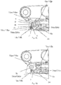
- Fig. 2 discloses a perspective view of the quick coupler with a front pin locking arrangement 19.
- the visible parts of the front pin locking arrangement is in the figure composed by the middle axle 17 which is fixed in a frame 4 preferably by a support axle 20a which runs through the respective lateral portions 4a and 4b of the frame, by the lateral portion sectors 4d and 4e, through the hollow middle axle 17.
- a locking plate 21a and 21b in one end of the support axle 10a clamps this in its direction of rotation using two non circular holes in which the non circular ends of the support axle 20a are adapted to fit.
- Around the middle axle 17 two locking segments 18a and 18b are arranged in order to rotate around the same.
- the locking segments 18a and 18b have preferably a non circular cam surface and each segment comprises a spring arrange to be biased to rotate in a first direction.
- the biasing of the locking segment 18a, 18b can be done for example by rotating the middle axle 17 in relation to these and the support axel 20a and then with a locking pin 20b which is inserted through the surface of the middle axle in the support axle 10a, lock the middle axle 17 in relation to the support axle 10a so that a relative rotation between the parts are no longer possible.
- the springs are encircled by o-rings arranged at the respective end of the locking segment in order to seal against dirt and moisture. (not disclosed)
- the locking segments 18a, 18b are preferably arranged in vicinity of the lateral part sectors 4d and 4e, by each end of the middle axle 17.
- Figure 3a and 3b shows detail views of the quick coupler when it is in an open position, i.e. when no tool is attached.
- Figure 2a shows a side view of the coupler and figure 2b a plan view of the coupler.
- the side view can be said to be a vertical view and the plan view a horizontal view, when the coupler is so arranged in space that the lower edge 1a of the coupler is arranged essentially horizontal to the ground. Since the quick coupler, especially if attached to a tilt rotator, can rotate around several axles, this position is only one out of several possible positions. Thus, when the expressions horizontal and vertical are used, reference is only made to figures 2a and 3a .
- the quick coupler 1 in figures 3a, 3b and figures 4a, 4b comprises an essentially rectangular frame 4 with two lateral portions 4a, 4b connected with each other by a frame body 4c (see fig. 2b , 3b ).
- the two lateral portions 4a, 4b have a first and a second cut-out 5, 6 arranged essentially perpendicular to each other, i.e. the first cut-out 5 is in the figure essentially horizontal and the second cut-out 6 is essentially vertical.
- the cut-outs 5, 6 are adapted to cooperate with the attachments pins 3a, 3b of the tool by means of a first attachment pin 3b is inserted in the first horizontal cut-out 5 and the second attachment pin 3a cooperates with and rests in the second vertical cut-out 6 (see also fig. 1 ).
- the attachment to the arm of the earth moving machine or the tilt rotator can be made through two holes 7a, 7b arranged in the lateral portions 4a, 4b.
- Said locking segments 18a, 18b are arranged to be rotated in relation to the frame 4 in at least a first and a second direction between two different positions, whereby the locking segment 18a, 18b in at least one position delimits the first cut-out 5, in a direction non-parallel with the first cut-out.
- the actuator 8 is a hydraulic cylinder, but it can also be an electrically operated engine, a compressed spring or another mechanical control arrangement.
- the actuator 8 is attached between on one side a locking arrangement 9 and on the other side a lock indication device 10 and the locking pistons 24a and 24b of the front pin locking arrangement 19 and is arranged to move the locking arrangement 9, the lock indication device 10 and the locking pistons 24a, 24b in relation to the frame 4.
- the actuator is arranged between on one side a locking arrangement 9 and on the other side a lock indication device 10 and the locking pistons 24a, 24b of the front pin locking arrangement 19 in that it is attached to the locking arrangement 9 and a locking plate 10c to which the lock indication device 10 is arranged, and there to arranged to move the locking arrangement 9 and the lock indication device 10 and the locking pistons 24a, 24b in relation to the frame 4.
- the lock indication device 10 is removed. Since the actuator 8 is placed between the locking arrangement 9 respective the lock indication device 10 and the locking pistons 24a, 24b, the locking arrangement 9 respective the lock indication device 10 and the locking pistons 24a, 24b is essentially simultaneously moved in opposite direction R1, R1.
- the locking arrangement 9 respective the lock indication device 10 and the locking pistons 24a, 24b are moved essentially parallel to the elongation direction of the first cut-out 5.
- the locking pistons are mechanically detached from the hydraulic cylinder, whereby the hydraulic cylinders only can actuate the movement of the locking pistons simultaneously in one direction.
- the direction of movement can in one embodiment be controlled by letting the locking plate 10c be led by a tension bolt 26 operating as a guide by letting the tension bolt 26 run through a lead-through in the locking plate 10c.
- a nut arranged on one end of the tension bolt prevents axial movement passed an end position. Due to this arrangement the actuator 8 is suspended in its one end.
- the actuator in the shape of a hydraulic cylinder 8 can be a cylinder comprising a piston 14 and a piston shaft 15, where the piston 14 delimit two fluid filled chambers in the cylinder.
- the adjustment between an open and a closed position is made by increasing or decreasing the pressure in the fluid filled chambers by means of a hydraulic valve 13.
- a compression spring 16 can be arranged in one or both chambers. The spring 16 operates as a safety feature and acts on the piston 14 if something should break and the internal pressure in the chambers should disappear.
- the locking arrangement 9 comprises as least one, in relation to the frame 4, moveable locking part 9a, 9b, with a first distal end 9ay, 9by and one second proximal end 9ai, 9bi.
- the distal end 9ay, 9by can be protruded out through an opening 11 in the frame 4 and lock one of the two locking pins 3a, 3b of the tool in the frame 4.
- the locking arrangement 9 can be said to have two positions; one first position (shown as an open position in figures 3a and 3b ) when the at least one locking part 9a, 9b is inserted in the frame 4 and a second position (shown as a locked position in figures 4a and 4b ) when the at least one locking part 9a, 9b protrudes from the frame 4 and delimits the second cutout 6 in a direction parallel to the first cutout 5.
- the second attachment pin 3b of the tool is safely locked in the quick coupler 1, i.e. the attachment pin 3b is prevented from being vertically pulled out from the second cutout 6.
- the at least one locking part 9a, 9b can also have a chamfer in its first distal end 9ay, 9by which is adapted after the shape of the one of the attachment pins 3a, 3b of the tool adapted to cooperate with the second cutout 6.
- the locking arrangement 9 comprises two cylindrically shaped and elongated locking parts 9a, 9b which are connected with each other by a yoke 9c.
- the locking parts 9a, 9b are arranged to run through a respective opening 11 in the frame 4.
- Each opening 11 can be sealed by a sealing and/or a scraper (not shown) in order to seal off the space in the frame 4 where the actuator 8 is placed from dirt and moisture.
- actuators are used in another embodiment. These actuators can be separate or connected and act directly or indirectly on respective locking part 9a, 9b.
- the actuators can be controlled individually by separate or common hydraulic valves or by electrical or mechanical arrangements. It is also possible to mechanically connect the actuators by a locking plate 10c.
- the lock indication device 10 comprises at least one elongated indication part 10a, 10b with a first distal end 10ay, 10by and a second proximal end 10ai, 10bi.
- the at least one indication part 10, 10b is arranged to run in an opening 12 in the frame 4 so that it in a first position is inserted in the frame 4 and in second position protrudes from the frame 4 and becomes visible from outside the frame 4.
- the distal end 10ay, 10by of the at least one indication part 10a, 10b can have a color different from the color of the frame 4. If a fluorescent color is used the indication part is also visible during darker conditions.
- the indication parts are two cylinders 10a, 10b connected with a connection part or locking plate 10c.
- the cylinders 10a, 10b are arranged to run parallel in two openings 12 in the frame 4. If two cylinders 10a, 10b are used to indicate if the lock is locked or open a better/ more secure display is achieved, especially when the observer is standing in a direction across from the side or directly under the tool and quick coupler.
- the two openings 12 in the frame 4 can comprise a seal and/or a scraper (not shown) in order to further seal off the space inside the frame 4.
- a seal and/or a scraper (not shown) in order to further seal off the space inside the frame 4.
- the front pin locking arrangement 19 comprises the locking pistons 24a, 24b, the locking segments 18a, 18b, with their respective spring (not shown) and the middle axle 17.
- the locking pistons comprise two essentially cylindrical parts which in one embodiment are connected to each other by the locking plate 10c. However, in a preferred embodiment the locking pistons are mechanically disconnected from both the locking plate 10c and the hydraulic cylinder 8, whereby the hydraulic cylinder through the locking plate 10c indirectly act on the locking pistons 24a, 24b and are thereby adapted to actuate movement of the locking pistons 24a, 24b in only one direction.
- the locking pistons are arranged to run through the respective hole 25a, 25b in the frame 4.
- Each hole 25a, 25b can be sealed by a seal and/or by a scraper (not shown) so that the interior of the frame 4 where the actuator is placed is sealed from dirt and moisture.
- the holes 25a, 25b are arranged at a position in the frame corresponding to the position of each locking segment 18a, 18b, so that the locking pistons 24a, 24b can be brought into contact with each locking segment 18a, 18b and a partial area of the locking plate 10c.
- the position of the holes 25a, 25b are preferably a bit vertically dislocated either upwards or downwards in relation to the center of rotation of the locking segments 18a, 18b.
- the locking pistons 24a, 24b are arranged to move essentially between an outer and an inner position. In the outer position at least one point or surface section of the outer ends 24ay, 24by of the locking pistons are located at a shorter first distance from the center of rotation 18ac, 18bc of the locking segments compared to an inner more inserted position in the frame 4 when this distance is larger compared to a second distance.
- a third distance can exist between the locking pistons 24a, 25b and the locking plate 10c, whereby the locking segments can rotate in both directions, i.e. in a second direction clockwise in the figure and a first direction anti-clockwise in the figure.
- the outer circumference of the locking segments are thus rotating freely because their maximum radius from the centre of rotation to the cam surface portion, which will bear against the outer ends 24ay, 24by of the locking pistons during rotation is smaller than the sum of a possible third distance between the locking plate 10c and the inner ends 24ai, 24bi of the locking pistons and the distance from the centre of rotation 18ac, 18bc of the locking segments 18a, 18b to the outer ends 24ay, 24by of the locking pistons, i.e. either the first or the second distance depending on the position of the locking device.
- the third distance will always be null.
- the third distance is also equal to null when the locking arrangement 9 is in a locked position.
- the cam surfaces of the locking segments 18a, 18b which have a relatively close distance to the centre of rotation 18ac, 18bc along the ends of the locking pistons 24a, 24b, will slide along the outer ends 24ay, 24by of the locking pistons whereby the locking pistons are not moved towards the locking plate 10c.
- a rotation in a first direction of the locking segments 18a, 18b a part of the cam surface on a relatively greater distance front the center of rotation 18ac, 18bc will be pressed towards the outer ends 24ay, 24by of the locking pistons so that they are transferred towards the locking plate 10c and an inner position until the locking segments are allowed to rotate free from the outer ends 24ay, 24by of the locking pistons.
- the maximum radius from the centre of rotation to the cam surface which will bear against the outer ends 24ay, 24by of the locking pistons during rotation is smaller than the sum of the third distance between the locking platen 10c and the inner ends 24ai, 24bi of the locking pistons and the distance from the centre of rotation 18ac, 18bc of the locking segments 18a, 18b to the outer ends 24ay, 24by of the locking pistons, i.e. the first or second distance depending on the position of the locking arrangement 9.
- a cam surface on a relatively greater distance from the centre of rotation 18ac, 18bc prevents rotation because it bear against the ends of the locking pistons 24a, 24b, whose movement in their turn are prevented by their contact against the locking plate 10c with their other ends 24ai, 24bi.
- the maximum radius from the centre of rotation 18ac, 18bc to the cam surface which will bear against the outer ends 24ay, 24by of the locking pistons during rotation is larger than the sum of the third distance between the locking plate 10c and the inner ends 24ai, 24bi of the locking pistons and the distance from the centre of rotation 18ac, 18bc of the locking segments 18a, 18b to the outer ends 24ay, 24by of the locking pistons corresponding to the first or the second distance depending on the position of the locking device 9.
- the front pin locking arrangement 19 comprises two locking pistons 24a and 24b moveably arranged in the holes 12 to move in an essentially horizontal direction, i.e. in parallel to the first horizontal cut-out 5 and the indication devices 10a and 10b between the outer and the inner position.
- Fig. 5a disclose the front pin locking arrangement 19 during insertion of a first attachment pin 3b, such as a front pin, when the locking arrangement 9 is in an open position and the locking pistons 24a, 24b are in an outer position.
- the first attachment pin 3b slides over the cam surfaces of the locking segments 18a, 18b and cause them to rotate in a second direction (clockwise in the figure) where after the first attachment pin 3b is inserted and rests in the first horizontal cut-out 5.
- the springs of the locking segments 18a, 18b will force the locking segments 18a, 18b to rotate in a first locking direction (counter clockwise in the figure) and enclose the attachment pin in the first horizontal cut-out.
- the at least one indication part 10a, 10b is arranged in an inserted position in the frame 4, whereby it is not visible from the outside of the frame 4.
- Fig. 5b shows the front pin locking arrangement 19 during insertion of a first attachment pin 3b, such as a front pin, in the first horizontal cut out 5 when the locking arrangement 9 is in a closed position.
- the first attachment pin 3b slides over the cam surfaces of the locking segments 18a, 18b and cause them to rotate in a second opening direction (clockwise in the figure) where after the first attachment pin 3b is inserted and rests in the first horizontal cut-out 5.
- the springs of the locking segments 18a, 18b will force the locking segments 18a, 18b to rotate in a first locking direction (counter clockwise in the figure) and enclose the attachment pin in the first horizontal cut-out.
- the at least one indication part 10a, 10b is arranged in a protruding position in the frame 4, whereby it is visible from the outside of the frame 4.
- Fig. 5c is the position after both Fig. 5a and Fig. 5b after the locking arrangement have been brought to a locked position, if it is not, as in Fig. 5b , already is in the locked position. Because the locking pistons 24a, 24b bear against the respective locking segment 18a, 18b at one of their ends, and against the locking plate 10c in their other ends, the locking segments can no longer rotate in the first direction and thereby the attachment pin 3b is locked in its position in the first horizontal cut-out 5.
- FIG 5c it is also shown how the at least one indication part 10a, 10b is in a protruded position out of the frame 4, whereby it is visible from the outside of the frame 4.
- the cam surface of the locking segment is shown, by which the radius from the centre of rotation 18ac, 18bc varies along the circumference of the locking segment, whereby the locking segment has a cam surface sector, which theoretically can be an infinitesimal small point along the circumference of the locking segment, at a corresponding first radius r1 and a second radius r2, whereby the first radius r1 is larger than the second radius r2.
- r2 can preferably be defined as being of such a length that its corresponding cam surface section is at a smaller distance a to the opposite wall of the opening when the at least one locking arrangement 9 is in a locked position and the first attachment pin 3b has been inserted to rest in the horizontal cut-out 5 and the locking segments are in a position where they delimit the first cut-out, so that a is smaller than D.
- the radius r1 can in the same position be defined as in the same position have a corresponding cam surface section which in this position bear against a part of the outer end 24ay, 24by of the locking piston.
- the contact can be touching as disclosed in figure 5c , where the cam surface section corresponding to r1 bear against the lower part of the outer end of the locking piston, but in this example it is obvious that several r1 can fulfill the demand of being longer than the first distance by the design of the essentially plane vertical cam surface section which bear against the majority of the outer end 24ay, 24by of the locking piston.
- Fig. 5d disclose the front pin locking arrangement 19 during insertion of a first attachment pin 3b, such as a front pin, in the first horizontal cut-out 5, when the locking arrangement is in an open position. Since a distance have been formed between the locking plate 10c and the inner ends 24ai, 24bi of the locking pistons and since the locking pistons 24a, 24b can be moved to a larger distance from the locking segments 18a, 18b and their centre of rotation, the locking segments 18a, 18b can be brought to rotate by letting their essentially plane surfaces press the locking pistons 24a, 24b in the direction towards the locking plate 10c and thereby they are free from the ends of the locking pistons 24a, 24b.
- the attachment pin 3b can be taken out from a position in the horizontal cut-out 5, to a position outside this and thus outside the attachment device.
- the at least one indication part 10a, 10b is in an inserted position in the frame 4, whereby it is not visible outside the frame 4.
- An operator which desires to switch tools or setting a tool free from its excavator, will put the locking arrangement in an open position, whereby the attachment pin 3a, can be set free from the tool coupler and its position in the vertical cut-out, by inserting the at least one locking part 9a, 9b in the frame 4.
- the attachment pin 3b can be brought out of its position in the horizontal cut-out 5 according o the description above.
Landscapes
- Engineering & Computer Science (AREA)
- Mechanical Engineering (AREA)
- Mining & Mineral Resources (AREA)
- Civil Engineering (AREA)
- General Engineering & Computer Science (AREA)
- Structural Engineering (AREA)
- Quick-Acting Or Multi-Walled Pipe Joints (AREA)
- Shovels (AREA)
- Portable Nailing Machines And Staplers (AREA)
Description
- The present invention relates generally to a quick coupler used for attaching a tool to an earth moving vehicle, where the quick coupler comprises a locking device and a front pin locking arrangement.
- Today it is very common that quick couplers are used for connecting different tools to an earth moving machine, for example an excavator, backhoe loader or a digger. With the quick coupler the driver can quickly and simply switch between different tools, for example different buckets, which can be used for s certain work condition. The quick coupling is mounted directly on the excavator art or on a on the arm mounted tilt rotator which allow tool movement in all directions. It can also be integrated in the tilt rotator. The quick coupling has in its lower part a locking mechanism adapted to lock the tool, either mechanically or with a hydraulically controlled lock. The locking mechanism often comprises a solid grip and a locking wedge or locking pins which locks the tool around parallel axles attached to the attachment bracket.
- Quick couplers can be divided into two groups; universal or dedicated. Universal quick couplers are characterized in that the quick coupler is constructed to be able to be used on tools originating from different tool manufactures. Since the tools originate from different tool manufacturers or different excavator models, the distance between the parallel axles can vary and the diameter of the axles can be different. Thus, a universal quick coupler normally fits tools with different distances between the axles and sometimes also fit tools with different axle diameter. Dedicated quick couplers are, on the other hand, based on a standard, which result in that the quick coupler only fits if the tool follows the standard from which the quick coupler is constructed. Only the upper part, i.e. the part mounted adjacent the excavator arm, varies while the locking mechanism follows a standard. The most common standard for quick couplers on the Nordic market is symmetrical quick couplers, which are based on a gate with two parallel axles.
- A problem with quick couplers of today is that it is a large risk that the driver drops the tool during the connection of the tool to the excavator, since the driver believe that the tool is securely locked with the locking mechanism even though this is not the case. The tool is lifted and run the risk of falling out from the front grip of the tool coupler due to gliding of the tool front axle.
- A number of attempts have been made to solve the above mentioned problem. In patent application
US2008/0193210A1 it is disclosed a coupling arrangement between a boom and a tool comprising a safety mechanism to prevent unintentional release of the tool. The document discloses a rotatable safety locking part which is spring suspended and biased towards a locking position. The locking part is with lock lever arms connected to a hydraulic cylinder part. The disadvantage with this solution is that it is not possible to securely lock the arrangement in all positions of the locking arrangement. For example when the hydraulic cylinder is in a locking position for safety locking, the safety locking part cannot rotate to receive an attachment pin. The positioning of an attachment pin first requires an activation of the hydraulic cylinder. -
WO2008/051095 A2 discloses a safety lock for one of the attachment pins comprising an hydraulic cylinder. Unlocking and locking of the safety lock occur actively through the cylinder. Just as in the previous mentioned document this solution does not permit locking of the safety lock for a locked position of the locking arrangement. -
EP1318242 B1 discloses a system for making safety locking possible. The disadvantage with the system is that safety locking is not possible when the locking arrangement is in a locked position. The positioning of the attachment pin in a cut out is not possible when the locking arrangement is locked, only when it is open. -
WO2010/062193A1 discloses a coupling arrangement for attachment of a working tool and a method for unlocking which requires several steps. The snap locking of a first attachment pin is possible by a floatingly suspended hydraulic cylinder, i.e. arranged to be able to move up and down in the coupling arrangement. The disengagement of the safety lock occurs actively by contraction of the hydraulic cylinder which thus is connected for this purpose. The disadvantage with this solution is that the floating suspension of a hydraulic cylinder, i.e. by letting a large number of included components be moveable, increases the risk of fatigue of the parts over time and thereto also the risk of failure in the locking arrangement which is a safety risk. In a manufacturing perspective it is also a disadvantage to be forced to predefine an exact movement space for the hydraulic cylinder to make unlocking possible. -
WO2005/026454 A1 discloses a safety lock for quick coupling of a tool. Safety locking is however not possible when the locking arrangement is in a locked position, and it requires a 180° rotation for unlocking. - Another problem with quick couplers of today is that the lock indication often is indistinct and not always secure. Today normally an indicator rod/ indicator pin is used which is connected to the locking arrangement of the quick coupler. This means that when the locking arrangement is retracted into the holder the lock is opened and the indicator rod becomes visible, which indicates that the lock is open. Such solutions are for example disclosed in
WO02097201A1 US6379075B1 andUS6132130A . Thus, the normal is that the quick coupler has a negative lock indication, i.e. it indicates when the lock is open. The risk with this solution is, if the indicator rod in either way is broken or removed the driver may believe that the lock is closed, since no indicator rod is visible, while it actually is open. In such case the risk is large that the tool is dropped, which can be dangerous for personnel working in the vicinity of the excavator. - Other locking arrangements are also know which makes it possible to indicate when the lock is locked. Such quick coupler lock indication arrangements are for example shown in
US20100189535A1 ,EP0527733B1 andUS5692855A . - In both
US20100189535A1 andEP0527733B1 a locking arrangement is disclosed having the shape of a, in relation to the quick coupler, laterally extending hydraulically actuated pin, which both see to that the lock remains locked and which, with a colored outer part visible for the driver, indicates that this is the case.US5692855A shows a coupling arrangement where a handle visible for the observer is turned together with the locking arrangement and indicates locked and unlocked position, respectively. - These solutions either demand an extra hydraulic actuator and/or several mechanically connected components which can be loose or break. Thus, there is a need for a simple and reliable lock indicator for a quick coupler which clearly indicated for that driver that the tool is securely locked to the excavator.
- An object of the present invention is to in a robust and safe way lock a quick coupler of an earth moving vehicle, for example an excavator, in a first and preferably a front attachment pin in a tool.
- A further object is to in a simple and clear way indicate when the quick coupler is locked.
- At least some of the above mentioned objects are achieved by the following:
- According to one invention a quick coupler for attaching a tool comprising an attachment bracket with two parallel attachment pins to an earth moving vehicle is presented, where the quick coupler comprises
- a frame with a first cut-out and a second cut-out arranged substantially perpendicular to each other, where the respective cut-out is adapted to cooperate with the respective attachment pin of the tool,
- at least one, in relation to the frame moveable locking arrangement, adapted to delimit the second cut-out in a direction parallel to the first cut-out, whereby one of the attachment pins of the tool is locked in the second cut-out
- at least one, in the frame arranged, actuator adapted to move the locking arrangement between a first open and a second locked position,
- at least one locking piston arranged to be moved between an inner and an outer position,
- at least one locking segment arranged to be rotated in relation to the frame in a first and a second direction between different positions, whereby the locking segment in at least one position delimit the first cut-out,
- where the at least one actuator is arranged between the locking arrangement and the at least one locking piston and is arranged to move both the locking arrangement and the at least one locking piston in relation to the frame,
- that the at least one locking segment is arranged in relation to the locking piston so that the at least one locking segment is prevented to rotate in a first direction when the locking arrangement is in a locked position and is allowed to rotate in the first direction when the locking arrangement is in an open position,
- that the at least one locking segment is arranged in relation the locking piston so that the locking segment is allowed to rotate in a second rotation direction when the locking arrangement is in either a locked or an open position,
- where the at least one locking segment is arranged to rotate in relation to the at least one locking piston.
- According to a further embodiment a quick coupler is presented, in which the at least one locking piston has an outer end and an inner end whereby the at least one locking segment is arranged in relation to the at least one locking piston so that at least some point in the outer end of the locking piston is located at a first distance from the centre of rotation of the at least one locking segment by an outer position when the at least one locking arrangement is in a locked position, and where at least some point on the outer end of the at least one locking piston is located on a second distance from the centre of rotation of the at least one locking segment by an inner position, when the at least one locking arrangement is in an unlocked position, where the first distance is less than the second distance, where the at least one locking segment has a cam surface, by which the radius from the centre of rotation to the cam surface varies along the circumference of the locking segment, whereby the locking segment has a cam surface section at a corresponding first radius r1 and a second radius r2, whereby the first radius r1 is larger than the second radius r2.
- According to another embodiment a quick coupler is presented, in which the first radius r1 of the at least one locking segment is larger than the first distance when the locking arrangement is in a locked position and smaller than the second distance when the at least one locking arrangement is in an open position and where the second radius r2 is smaller than the first distance when the at least one locking arrangement is in a locked position and smaller than the second distance when the at least one locking arrangement is in an open position.
- According to another embodiment a quick coupler is presented, in which a locking plate is arranged to the hydraulic cylinder, whereby the inner end of the at least one locking piston is mechanically disconnected from the locking plate, whereby the inner end of the at least one locking piston is at a third distance from the locking plate, whereby the third distance is null when the at least one locking arrangement is in a locked position.
- According to one embodiment a quick coupler is presented, in which the first radius r1 of the at least one locking segment is larger than the sum of the second distance and the third distance when the at least one locking arrangement is in a locked position and smaller than the sum of the first and the third distance when the at least one locking arrangement is in an open position and where the second radius r2 is smaller than the sum of the first and the third distance when the at least one locking arrangement is in a locked position and smaller than the sum of the second and the third distance when the at least one locking arrangement is in an open position.
- According to one embodiment a quick coupler is presented, in which a first attachment pin with a first diameter D is adapted to be inserted through an opening to rest in a horizontal first cut-out, whereby the second radius r2 is defined by having a corresponding cam surface section located on a shortest distance a to the opposite wall of the opening when the at least one locking arrangement is located in a locked position and the first attachment pin is inserted to rest in the horizontal first cut-out and the at least one locking segment is limiting the first cut-out, whereby the first radius r1 is defined as having a cam surface section which at this position touches a part of the outer ends of the at least one locking piston, whereby the first radius r1 is of such a length that the first diameter D is larger than the shortest distance a to the opposite wall of the opening when the at least one locking arrangement is located in a locked position and the first attachment pin is inserted to rest in the horizontal cut-out and the at least one locking segment delimits the first cut-out.
- According to one embodiment a quick coupler is presented, in which the at least one locking piston is adapted to be moved essentially linearly by the at least one actuator in at least one direction essentially parallel to the extension direction of the first cut-out.
- According to one embodiment a quick coupler is presented, in which the at least one locking arrangement and the at least one locking piston are arranged to be moved essentially simultaneously in opposite directions.
- According to one embodiment a quick coupler is presented, in which a spring is arranged in connection to the at least one locking segment with the purpose of biasing the at least one locking segment in a first direction of rotation.
- According to one embodiment a quick coupler is presented, which comprises a lock indication device which visually indicates if the locking arrangement is in an open or closed position, in which the at least one actuator is arranged between the at least one locking arrangement and the at least one lock indication device and is arranged to move both the at least one locking arrangement and the lock indication device in relation to the frame so that the lock indication device visually indicates when the at least one locking arrangement is in the locked position, whereby the lock indication device and the at least one locking piston are arranged in the locking plate on the same side of the at least one actuator.
- The invention is now described, by way of example, with reference to the accompanying drawings, in which:
-
Fig. 1 shows a quick coupler attached to a tool, -
Fig. 2 shows a perspective view of a quick coupler and in particular the front pin locking arrangement, -
Fig. 3a shows a side view of a quick coupler in an unlocked position, -
Fig. 3b shows a plan view of a quick coupler in an unlocked position, -
Fig. 4a shows a second plan view of a quick coupler in an unlocked position, and -
Fig. 4b shows a plan view of a quick coupler in a locked position,Fig. 3a shows a first vertical view of a quick coupler in a closed position, -
Fig. 5a shows a front pin locking arrangement according toFig. 4a and Fig. 4b in a locked position during insertion of a front pin, -
Fig. 5b shows a front pin locking arrangement according toFig. 3a and Fig. 3b in an unlocked position during insertion of a front pin, -
Fig. 5c shows a front pin locking arrangement where the front pin is clamped, and -
Fig. 5d a front pin locking arrangement according toFig. 3a and Fig. 3b in an unlocked position during exit of a front pin. - In the following, it is provided a detailed description of embodiments:
Figure 1 shows aquick coupler 1 attached in its lower part 1a in atool 2, in this case a bucket. Thequick coupler 1 is attached to the tool by means of anattachment bracket 3, which is a frame comprising two parallel attachment pins 3a, 3b which extend in a direction essentially parallel to bothtool 2 andquick coupler 1. The upper part 1b of the quick coupler can be directly attached to an arm of an earth moving machine, for example an excavator, digger or any other machine adapted to perform earth moving operations. Thequick coupler 1 can also be mounted by or integrated in a, on the arm mounted, tilt rotator which permits tool movement in all directions (not disclosed). -
Fig. 2 discloses a perspective view of the quick coupler with a frontpin locking arrangement 19. The visible parts of the front pin locking arrangement is in the figure composed by themiddle axle 17 which is fixed in aframe 4 preferably by asupport axle 20a which runs through therespective lateral portions lateral portion sectors 4d and 4e, through the hollowmiddle axle 17. A lockingplate 21a and 21b in one end of thesupport axle 10a clamps this in its direction of rotation using two non circular holes in which the non circular ends of thesupport axle 20a are adapted to fit. Around themiddle axle 17 twolocking segments segments locking segment middle axle 17 in relation to these and thesupport axel 20a and then with alocking pin 20b which is inserted through the surface of the middle axle in thesupport axle 10a, lock themiddle axle 17 in relation to thesupport axle 10a so that a relative rotation between the parts are no longer possible. The springs are encircled by o-rings arranged at the respective end of the locking segment in order to seal against dirt and moisture. (not disclosed) Thelocking segments lateral part sectors 4d and 4e, by each end of themiddle axle 17. -
Figure 3a and 3b shows detail views of the quick coupler when it is in an open position, i.e. when no tool is attached.Figure 2a shows a side view of the coupler andfigure 2b a plan view of the coupler. The side view can be said to be a vertical view and the plan view a horizontal view, when the coupler is so arranged in space that the lower edge 1a of the coupler is arranged essentially horizontal to the ground. Since the quick coupler, especially if attached to a tilt rotator, can rotate around several axles, this position is only one out of several possible positions. Thus, when the expressions horizontal and vertical are used, reference is only made tofigures 2a and3a . - The
quick coupler 1 infigures 3a, 3b andfigures 4a, 4b comprises an essentiallyrectangular frame 4 with twolateral portions fig. 2b ,3b ). The twolateral portions out out 5 is in the figure essentially horizontal and the second cut-out 6 is essentially vertical. The cut-outs first attachment pin 3b is inserted in the first horizontal cut-out 5 and thesecond attachment pin 3a cooperates with and rests in the second vertical cut-out 6 (see alsofig. 1 ). The attachment to the arm of the earth moving machine or the tilt rotator can be made through twoholes lateral portions 4a, 4b. Said lockingsegments frame 4 in at least a first and a second direction between two different positions, whereby thelocking segment out 5, in a direction non-parallel with the first cut-out. - In the
rectangular frame 4 at least oneactuator 8 is arranged. In this embodiment theactuator 8 is a hydraulic cylinder, but it can also be an electrically operated engine, a compressed spring or another mechanical control arrangement. In one embodiment theactuator 8 is attached between on one side alocking arrangement 9 and on the other side a lock indication device 10 and thelocking pistons pin locking arrangement 19 and is arranged to move thelocking arrangement 9, the lock indication device 10 and thelocking pistons frame 4. In another embodiment the actuator is arranged between on one side alocking arrangement 9 and on the other side a lock indication device 10 and thelocking pistons pin locking arrangement 19 in that it is attached to thelocking arrangement 9 and alocking plate 10c to which the lock indication device 10 is arranged, and there to arranged to move thelocking arrangement 9 and the lock indication device 10 and thelocking pistons frame 4. In another embodiment the lock indication device 10 is removed. Since theactuator 8 is placed between the lockingarrangement 9 respective the lock indication device 10 and thelocking pistons arrangement 9 respective the lock indication device 10 and thelocking pistons figure 1-4 thelocking arrangement 9 respective the lock indication device 10 and thelocking pistons out 5. In one embodiment the locking pistons are mechanically detached from the hydraulic cylinder, whereby the hydraulic cylinders only can actuate the movement of the locking pistons simultaneously in one direction. The direction of movement can in one embodiment be controlled by letting the lockingplate 10c be led by atension bolt 26 operating as a guide by letting thetension bolt 26 run through a lead-through in thelocking plate 10c. A nut arranged on one end of the tension bolt prevents axial movement passed an end position. Due to this arrangement theactuator 8 is suspended in its one end. - The actuator in the shape of a
hydraulic cylinder 8 can be a cylinder comprising apiston 14 and apiston shaft 15, where thepiston 14 delimit two fluid filled chambers in the cylinder. The adjustment between an open and a closed position is made by increasing or decreasing the pressure in the fluid filled chambers by means of ahydraulic valve 13. In one or both chambers, acompression spring 16 can be arranged. Thespring 16 operates as a safety feature and acts on thepiston 14 if something should break and the internal pressure in the chambers should disappear. - The locking
arrangement 9 comprises as least one, in relation to theframe 4,moveable locking part opening 11 in theframe 4 and lock one of the two lockingpins frame 4. Thus, the lockingarrangement 9 can be said to have two positions; one first position (shown as an open position infigures 3a and 3b ) when the at least one lockingpart frame 4 and a second position (shown as a locked position infigures 4a and 4b ) when the at least one lockingpart frame 4 and delimits thesecond cutout 6 in a direction parallel to thefirst cutout 5. In such a way thesecond attachment pin 3b of the tool is safely locked in thequick coupler 1, i.e. theattachment pin 3b is prevented from being vertically pulled out from thesecond cutout 6. The at least one lockingpart second cutout 6. - According to the embodiment shown in
figures 3 and4 , the lockingarrangement 9 comprises two cylindrically shaped and elongated lockingparts yoke 9c. The lockingparts respective opening 11 in theframe 4. Eachopening 11 can be sealed by a sealing and/or a scraper (not shown) in order to seal off the space in theframe 4 where theactuator 8 is placed from dirt and moisture. - It is also conceivable that two or more actuators are used in another embodiment. These actuators can be separate or connected and act directly or indirectly on
respective locking part plate 10c. - The lock indication device 10 comprises at least one
elongated indication part indication part 10, 10b is arranged to run in anopening 12 in theframe 4 so that it in a first position is inserted in theframe 4 and in second position protrudes from theframe 4 and becomes visible from outside theframe 4. In order to make it even easier for the observer, which can be the driver or other person, to see the indication part, the distal end 10ay, 10by of the at least oneindication part frame 4. If a fluorescent color is used the indication part is also visible during darker conditions. - In the embodiment according to
figures 3 and4 the indication parts are twocylinders plate 10c. Thecylinders openings 12 in theframe 4. If twocylinders - The two
openings 12 in theframe 4 can comprise a seal and/or a scraper (not shown) in order to further seal off the space inside theframe 4. Of course it is also possible to enclose the entire space inside theframe 4, for example by attaching a lid (not disclosed) to the frame base 4c. If theactuator 8 is placed in a sealed space, the life of the actuator is increased. - As is clear from
Fig. 3 andFig. 4 the frontpin locking arrangement 19 comprises the lockingpistons segments middle axle 17. The locking pistons comprise two essentially cylindrical parts which in one embodiment are connected to each other by the lockingplate 10c. However, in a preferred embodiment the locking pistons are mechanically disconnected from both thelocking plate 10c and thehydraulic cylinder 8, whereby the hydraulic cylinder through the lockingplate 10c indirectly act on thelocking pistons pistons respective hole frame 4. Eachhole frame 4 where the actuator is placed is sealed from dirt and moisture. Theholes segment pistons segment plate 10c. The position of theholes segments segments holes pistons plate 10c and thehydraulic cylinder 8 is that you can prevent entering of dirt and moisture through theholes pistons holes plate 10c and thecylinder 8. - The locking
pistons frame 4 when this distance is larger compared to a second distance. When the locking arrangement is in an open position according toFig. 3a-3b , a third distance can exist between the lockingpistons plate 10c, whereby the locking segments can rotate in both directions, i.e. in a second direction clockwise in the figure and a first direction anti-clockwise in the figure. The outer circumference of the locking segments are thus rotating freely because their maximum radius from the centre of rotation to the cam surface portion, which will bear against the outer ends 24ay, 24by of the locking pistons during rotation is smaller than the sum of a possible third distance between the lockingplate 10c and the inner ends 24ai, 24bi of the locking pistons and the distance from the centre of rotation 18ac, 18bc of the lockingsegments plate 10c is connected to thelocking pistons locking arrangement 9 is in a locked position. - During a rotation in the second direction the cam surfaces of the locking
segments pistons plate 10c. During a rotation in a first direction of the lockingsegments plate 10c and an inner position until the locking segments are allowed to rotate free from the outer ends 24ay, 24by of the locking pistons. The maximum radius from the centre of rotation to the cam surface which will bear against the outer ends 24ay, 24by of the locking pistons during rotation is smaller than the sum of the third distance between the lockingplaten 10c and the inner ends 24ai, 24bi of the locking pistons and the distance from the centre of rotation 18ac, 18bc of the lockingsegments locking arrangement 9. - When the
locking arrangement 9 is in a locked position according toFig. 4a-4b the locking pistons bear on one sides against therespective locking segment plate 10c, whereby the locking segments due to their cam surface design can be brought into rotation in the second direction, but not in the first direction. In the other direction the cam surface of the lockingsegments pistons pistons plate 10c with their other ends 24ai, 24bi. The maximum radius from the centre of rotation 18ac, 18bc to the cam surface which will bear against the outer ends 24ay, 24by of the locking pistons during rotation is larger than the sum of the third distance between the lockingplate 10c and the inner ends 24ai, 24bi of the locking pistons and the distance from the centre of rotation 18ac, 18bc of the lockingsegments locking device 9. -
Fig. 5a-5d discloses components of the front pin locking arrangement and their possible locations in more detail. The frontpin locking arrangement 19 comprises two lockingpistons holes 12 to move in an essentially horizontal direction, i.e. in parallel to the first horizontal cut-out 5 and theindication devices -
Fig. 5a disclose the frontpin locking arrangement 19 during insertion of afirst attachment pin 3b, such as a front pin, when thelocking arrangement 9 is in an open position and thelocking pistons first attachment pin 3b slides over the cam surfaces of the lockingsegments first attachment pin 3b is inserted and rests in the first horizontal cut-out 5. After theattachment pin 3b have slide pass the lockingsegments segments segments indication part frame 4, whereby it is not visible from the outside of theframe 4. -
Fig. 5b shows the frontpin locking arrangement 19 during insertion of afirst attachment pin 3b, such as a front pin, in the first horizontal cut out 5 when thelocking arrangement 9 is in a closed position. Thefirst attachment pin 3b slides over the cam surfaces of the lockingsegments first attachment pin 3b is inserted and rests in the first horizontal cut-out 5. After theattachment pin 3b have slide pass the lockingsegments segments segments indication part frame 4, whereby it is visible from the outside of theframe 4. -
Fig. 5c is the position after bothFig. 5a and Fig. 5b after the locking arrangement have been brought to a locked position, if it is not, as inFig. 5b , already is in the locked position. Because the lockingpistons respective locking segment plate 10c in their other ends, the locking segments can no longer rotate in the first direction and thereby theattachment pin 3b is locked in its position in the first horizontal cut-out 5. An operator about to attach a tool to an excavator thereafter angle the tool coupler in such an angle that theattachment pin 3b rests in its position in the horizontal cut-out 5 without sliding out when the locking arrangement is brought in an open position, at the same time as the tool coupler is even more angled so that the vertical cut-out 6 is brought towards thesecond attachment pin 3a. When the attachment pin is brought into contact with the vertical cut-out 6, the locking arrangement is put into a locked position whereby the at least one lockingpart frame 4 and delimits the second cut-out 6 in a direction parallel with the first cut-out 5. In this way thesecond attachment pin 3a of the tool is securely locked in thequick coupler 1, i.e. theattachment pin 3a is prevented from being vertically pulled out of the second cut-out 6, at the same time as the front attachment pin is locked in the horizontal cut-out. The tool is now locked to the quick coupler. - In
figure 5c it is also shown how the at least oneindication part frame 4, whereby it is visible from the outside of theframe 4. In the samefigure 5c the cam surface of the locking segment is shown, by which the radius from the centre of rotation 18ac, 18bc varies along the circumference of the locking segment, whereby the locking segment has a cam surface sector, which theoretically can be an infinitesimal small point along the circumference of the locking segment, at a corresponding first radius r1 and a second radius r2, whereby the first radius r1 is larger than the second radius r2. What so far has been described as a relatively larger distance between the cam surface to the centre of rotation thus corresponds to the radius r1 and a relatively shorter distance to the centre of rotation correspond to r2. In the figure it is shown that theattachment pin 3b has a diameter D. In order to firmly hold the attachment pin in place when it rests in the horizontal cut-out 5, r2 can preferably be defined as being of such a length that its corresponding cam surface section is at a smaller distance a to the opposite wall of the opening when the at least onelocking arrangement 9 is in a locked position and thefirst attachment pin 3b has been inserted to rest in the horizontal cut-out 5 and the locking segments are in a position where they delimit the first cut-out, so that a is smaller than D. The radius r1 can in the same position be defined as in the same position have a corresponding cam surface section which in this position bear against a part of the outer end 24ay, 24by of the locking piston. The contact can be touching as disclosed infigure 5c , where the cam surface section corresponding to r1 bear against the lower part of the outer end of the locking piston, but in this example it is obvious that several r1 can fulfill the demand of being longer than the first distance by the design of the essentially plane vertical cam surface section which bear against the majority of the outer end 24ay, 24by of the locking piston. -
Fig. 5d disclose the frontpin locking arrangement 19 during insertion of afirst attachment pin 3b, such as a front pin, in the first horizontal cut-out 5, when the locking arrangement is in an open position. Since a distance have been formed between the lockingplate 10c and the inner ends 24ai, 24bi of the locking pistons and since the lockingpistons segments segments pistons plate 10c and thereby they are free from the ends of the lockingpistons attachment pin 3b can be taken out from a position in the horizontal cut-out 5, to a position outside this and thus outside the attachment device. In the figure it is also shown how the at least oneindication part frame 4, whereby it is not visible outside theframe 4. An operator which desires to switch tools or setting a tool free from its excavator, will put the locking arrangement in an open position, whereby theattachment pin 3a, can be set free from the tool coupler and its position in the vertical cut-out, by inserting the at least one lockingpart frame 4. During a maintained open position of the locking device theattachment pin 3b can be brought out of its position in the horizontal cut-out 5 according o the description above.
Claims (10)
- A quick coupler for attaching a tool (2), comprising an attachment bracket with two parallel attachment pins (3a, 3b), to an earth moving vehicle, wherein the quick coupler (1) comprises
a frame (4) with a first cutout (5) and a second cutout (6) arranged substantially perpendicular to each other, where the respective cutout is adapted to cooperate with the respective attachment pin (3a, 3b) of the tool (2),
at least one, in relation to the frame (4) moveable locking arrangement (9), adapted to delimit the second cutout (6) in a direction parallel to the first cutout (5),whereby one of the attachment pins (3a, 3b) of the tool is locked up in the cutout (6),
at least one, in the frame (4) arranged, actuator (8) adapted to move the locking arrangement (9) between a first open and a second locked position, and
at least one locking segment (18a, 18b) arranged to be rotated in relation to the frame (4) in a first and a second direction between different positions, whereby the locking segment (18a, 18b) in at least one position delimit the first cut-out (5),
characterized in that the quick coupler (1) further comprises at least one locking piston (24a, 24b) arranged to move between an inner and an outer position, and characterized in that the at least one actuator (8) is arranged between the locking arrangement (9) and the at least one locking piston (24a, 24b) and is arranged to move both the locking arrangement (9) and the at least one locking piston (24a, 24b) in relation to the frame (4),
that the at least one locking segment (18a, 18b) is arranged in relation to the locking piston (24a, 24b) so that the at least one locking segment (18a, 18b) is prevented to rotate in a first direction when the locking arrangement (9) is in a locked position and is allowed to rotate in the first direction when the locking arrangement (9) is in an open position,
that the at least one locking segment (18a, 18b) is arranged in relation the locking piston (24a, 24b) so that the locking segment (18a, 18b) is allowed to rotate in a second rotation direction when the locking arrangement (9) is in either a locked or an open position,
where the at least one locking segment (18a, 18b) is arranged to rotate in relation to the at least one locking piston (24a, 24b). - A quick coupler according to claim 1, characterized in that the at least one locking piston has an outer end (24ay, 24by) and an inner end (24ai, 24bi) whereby the at least one locking segment (18a, 18b) is arranged in relation to the at least one locking piston so that at least some point in the outer end of the locking piston is located at a first distance from the centre of rotation (18ac, 18bc) of the at least one locking segment by an outer position when the at least one locking arrangement (9) is in a locked position, and where at least some point on the outer end (24ay, 24by) of the at least one locking piston is located on a second distance from the centre of rotation (18ac, 18bc) of the at least one locking segment by an inner position, when the at least one locking arrangement (9) is in an unlocked position, where the first distance is less than the second distance, where the at least one locking segment has a cam surface, by which the radius from the centre of rotation to the cam surface varies along the circumference of the locking segment, whereby the locking segment has a cam surface section at a corresponding first radius (r1) and a second radius (r2), whereby the first radius (r1) is larger than the second radius (r2).
- A quick coupler according to claim 2, characterized in that the first radius (r1) of the at least one locking segment is larger than the first distance when the locking arrangement (9) is in a locked position and smaller than the second distance when the at least one locking arrangement (9) is in an open position and where the second radius (r2) is smaller than the first distance when the at least one locking arrangement (9) is in a locked position and smaller that the second distance when the at least one locking arrangement (9) is in an open position.
- A quick coupler according to claim 2, characterized in that a locking plate (10c) is arranged to the hydraulic cylinder (8), whereby the inner end (24ai, 24bi) of the at least one locking piston is mechanically disconnected from the locking plate (10c), whereby the inner end (24ai, 24bi) of the at least one locking piston is at a third distance from the locking plate (10c), whereby the third distance is null when the at least one locking arrangement (9) is in a locked position.
- A quick coupler according to the claims 1, 2 and 4, characterized in that the first radius (r1) of the at least one locking segment (18a, 18b) is larger than the sum of the first distance and the third distance when the at least one locking arrangement (9) is in a locked position and smaller than the sum of the second and the third distance when the at least one locking arrangement (9) is in an open position and where the second radius (r2) is smaller than the sum of the first and the third distance when the at least one locking arrangement (9) is in a locked position and smaller than the sum of the second and the third distance when the at least one locking arrangement (9) is in an open position.
- A quick coupler according to claim 3 or 5, characterized in that a first attachment pin (3b) with a first diameter (D) is adapted to be inserted through an opening to rest in a horizontal first cut-out (5), whereby the second radius (r2) is defined by having a corresponding cam surface section located on a shortest distance (a) to the opposite wall of the opening when the at least one locking arrangement (9) is located in a locked position and the first attachment pin (3b) is inserted to rest in the horizontal first cut-out (5) and the at least one locking segment (18a, 18b) is limiting the first cut-out (5), whereby the first radius (r1) is defined as having a cam surface section which at this position touches a part of the outer ends (24ay, 24by) of the at least one locking piston, whereby the first radius (r1) is of such a length that the first diameter (D) is larger than the shortest distance (a) to the opposite wall of the opening when the at least one locking arrangement (9) is located in a locked position and the first attachment pin (3b) is inserted to rest in the horizontal cut-out (5) and the at least one locking segment (18a, 18b) delimits the first cut-out (5).
- A quick coupler according to any of the previous claims 1-6, characterized in that the at least one locking piston (24a, 24b) is adapted to be moved essentially linearly by the at least one actuator (8) in at least one direction essentially parallel to the extension direction of the first cut-out (5).
- A quick coupler according to claim 7, characterized in that the at least one locking arrangement (9) and the at least one locking piston (24a, 24b) are arranged to be moved essentially simultaneously in opposite directions (R1, R2).
- A quick coupler according to any of the previous claims 1-8, characterized in that a spring is arranged in connection to the at least one locking segment (18a, 18b) with the purpose of biasing the at least one locking segment (18a, 18b) in a first direction of rotation.
- A quick coupler according to any of the previous claims 4-9, characterized in that the quick coupler further comprises a lock indication device (10) which visually indicates if the locking arrangement (9) is in an open or closed position, in which the at least one actuator (8) is arranged between the at least one locking arrangement (9) and the at least one lock indication device (10) and is arranged to move both the at least one locking arrangement (9) and the lock indication device (10) in relation to the frame (4) so that the lock indication device (10) visually indicates when the at least one locking arrangement (9) is in the locked position, whereby the lock indication device and the at least one locking piston (24a, 24b) are arranged in the locking plate (10c) on the same side of the at least one actuator (8).
Applications Claiming Priority (2)
| Application Number | Priority Date | Filing Date | Title |
|---|---|---|---|
| SE1150837A SE536061C2 (en) | 2011-09-15 | 2011-09-15 | Front axle locking for attachment |
| PCT/SE2012/050953 WO2013048308A1 (en) | 2011-09-15 | 2012-09-11 | Front pin lock for a tool attachment device |
Publications (3)
| Publication Number | Publication Date |
|---|---|
| EP2766529A1 EP2766529A1 (en) | 2014-08-20 |
| EP2766529A4 EP2766529A4 (en) | 2015-08-19 |
| EP2766529B1 true EP2766529B1 (en) | 2019-06-19 |
Family
ID=47996080
Family Applications (1)
| Application Number | Title | Priority Date | Filing Date |
|---|---|---|---|
| EP12835960.1A Not-in-force EP2766529B1 (en) | 2011-09-15 | 2012-09-11 | Front pin lock for a tool attachment device |
Country Status (4)
| Country | Link |
|---|---|
| US (1) | US9783951B2 (en) |
| EP (1) | EP2766529B1 (en) |
| SE (1) | SE536061C2 (en) |
| WO (1) | WO2013048308A1 (en) |
Cited By (2)
| Publication number | Priority date | Publication date | Assignee | Title |
|---|---|---|---|---|
| EP3954835A2 (en) | 2020-08-11 | 2022-02-16 | Emtec Engineering & Maschinentechnik GmbH | Connecting device for coupling an implement to a working device and working device |
| WO2023119336A1 (en) * | 2021-12-23 | 2023-06-29 | Cangini Benne S.R.L. | Quick coupling |
Families Citing this family (7)
| Publication number | Priority date | Publication date | Assignee | Title |
|---|---|---|---|---|
| SE535681C2 (en) * | 2011-03-17 | 2012-11-06 | Steelwrist Ab | Quick attachment for a construction machine |
| CH710006A1 (en) | 2014-08-20 | 2016-02-29 | Josef Martin Gmbh | Quick-change coupling for coupling an implement to a dipper. |
| SE539425C2 (en) | 2014-09-03 | 2017-09-19 | Ytf Sweden Ab | Quick coupler for attaching a hydraulically operated tool / implement to an excavator |
| DE102017110586B4 (en) * | 2017-05-16 | 2023-03-23 | OilQuick Deutschland KG | Quick coupler and quick change system with such a quick coupler |
| KR101809005B1 (en) * | 2017-07-04 | 2017-12-15 | 황윤국 | Bucket link for excavator |
| DE102018105049A1 (en) * | 2018-03-06 | 2019-09-12 | Oilquick Deutschland Gmbh | Quick coupler |
| SE545709C2 (en) * | 2022-04-13 | 2023-12-12 | Steelwrist Ab | Lock indicator arrangement and method for a quick coupler and quick coupler comprising the same |
Family Cites Families (25)
| Publication number | Priority date | Publication date | Assignee | Title |
|---|---|---|---|---|
| US5010962A (en) * | 1990-04-30 | 1991-04-30 | Caterpillar Inc. | Indicating apparatus for a coupling |
| US5692855A (en) * | 1994-06-21 | 1997-12-02 | Farmers' Factory Co. | Automatic quick-connect coupler for implements |
| GB9520448D0 (en) * | 1995-10-06 | 1995-12-06 | Mccann Noel P M | Excavator hitch |
| JPH1082066A (en) * | 1996-09-05 | 1998-03-31 | Marujiyun Juko Kk | Attachment connecting coupler for earth-moving equipment |
| DE29705609U1 (en) * | 1997-04-02 | 1997-07-24 | Leh, Karl Heinz Josef, 55765 Birkenfeld | Safety device for a quick coupling of a working attachment on tillage equipment |
| SE510716C2 (en) * | 1997-10-02 | 1999-06-14 | Soneruds Maskin Ab | Quick fit coupling for mounting work tool on heavy machinery |
| US6379075B1 (en) * | 2000-01-18 | 2002-04-30 | Gh Hensley Industries, Inc. | Quick coupler apparatus |
| AUPR533701A0 (en) * | 2001-05-29 | 2001-06-21 | Ephemere Pty Ltd | A coupling assembly |
| ATE342406T1 (en) * | 2001-12-06 | 2006-11-15 | Geith Patents Ltd | QUICK TOOL COUPLING FOR COUPLING AN ATTACHMENT TO AN EXCAVATOR ARM AND THE QUICK TOOL COUPLING COMPRISES A CONTROL SYSTEM |
| US6902346B2 (en) * | 2002-03-15 | 2005-06-07 | Hendrix Manufacturing, Ltd. | Hydraulic coupler |
| IES20040194A2 (en) * | 2003-09-18 | 2005-03-23 | Caroline Mccormick | An excavator tool quick attachment device |
| EP1852555B1 (en) * | 2006-05-02 | 2012-09-12 | Kinshofer GmbH | A safety locking device for a quick coupler |
| WO2008029112A2 (en) * | 2006-09-04 | 2008-03-13 | Miller Uk Limited | Coupler |
| ATE488648T1 (en) * | 2006-09-13 | 2010-12-15 | Ian Hill | CLUTCH FOR EXCAVATORS |
| NZ550869A (en) * | 2006-10-26 | 2008-11-28 | J B Sales Internat Ltd | A coupler with latch for twin pin digger bucket |
| US7648305B2 (en) * | 2007-02-08 | 2010-01-19 | Cws Industries (Mfg.) Corp. | Pin grabber coupler |
| US7984575B2 (en) * | 2007-07-05 | 2011-07-26 | Caterpillar Inc. | Quick coupler assembly |
| AU2009220315B2 (en) * | 2008-03-07 | 2015-11-05 | Wedgelock Equipment Limited | Coupler for earth moving or materials handling machine |
| US20090282712A1 (en) * | 2008-05-15 | 2009-11-19 | Pruszynski Edwin | Coupler for excavating machines and the like |
| EP2373849B1 (en) * | 2008-11-03 | 2017-03-29 | Doherty Engineered Attachments Limited | Improvements to work attachment assemblies |
| US8262310B2 (en) | 2008-11-20 | 2012-09-11 | Paladin Brands Group, Inc. | Coupler with secondary lock on front hook |
| CA2651295A1 (en) * | 2009-01-27 | 2010-07-27 | Nye Manufacturing Ltd. | Coupler device to connect bucket or tool to boom arm |
| GB2467380B (en) * | 2009-02-03 | 2010-12-22 | Miller Int Ltd | Fully automatic coupler for excavator arm |
| US8782931B2 (en) * | 2009-12-09 | 2014-07-22 | S T Couplers Limited | Couplers |
| US8585345B2 (en) * | 2010-03-26 | 2013-11-19 | Paladin Brands Group, Inc. | Coupler with pivoting front hook lock |
-
2011
- 2011-09-15 SE SE1150837A patent/SE536061C2/en not_active IP Right Cessation
-
2012
- 2012-09-11 WO PCT/SE2012/050953 patent/WO2013048308A1/en not_active Ceased
- 2012-09-11 US US14/345,245 patent/US9783951B2/en not_active Expired - Fee Related
- 2012-09-11 EP EP12835960.1A patent/EP2766529B1/en not_active Not-in-force
Non-Patent Citations (1)
| Title |
|---|
| None * |
Cited By (4)
| Publication number | Priority date | Publication date | Assignee | Title |
|---|---|---|---|---|
| EP3954835A2 (en) | 2020-08-11 | 2022-02-16 | Emtec Engineering & Maschinentechnik GmbH | Connecting device for coupling an implement to a working device and working device |
| DE102020121067A1 (en) | 2020-08-11 | 2022-02-17 | emtec Engineering & Maschinentechnik GmbH | Connection device for coupling an attachment to a working device and working device |
| WO2023119336A1 (en) * | 2021-12-23 | 2023-06-29 | Cangini Benne S.R.L. | Quick coupling |
| EP4636171A3 (en) * | 2021-12-23 | 2025-12-31 | Cangini Benne S.R.L. | QUICK COUPLING |
Also Published As
| Publication number | Publication date |
|---|---|
| EP2766529A4 (en) | 2015-08-19 |
| SE536061C2 (en) | 2013-04-23 |
| WO2013048308A1 (en) | 2013-04-04 |
| US20140341648A1 (en) | 2014-11-20 |
| SE1150837A1 (en) | 2013-03-16 |
| US9783951B2 (en) | 2017-10-10 |
| EP2766529A1 (en) | 2014-08-20 |
Similar Documents
| Publication | Publication Date | Title |
|---|---|---|
| EP2766529B1 (en) | Front pin lock for a tool attachment device | |
| EP2686490B1 (en) | Quick coupler for an earth moving machine | |
| EP2466015B1 (en) | Attachment coupler for heavy machinery | |
| KR101033020B1 (en) | Heavy Duty Attachment Coupler with Attachment Safety Lock | |
| EP3052707B1 (en) | A coupler device | |
| KR101021926B1 (en) | Attachment Coupler for Heavy Equipment | |
| EP2076631B1 (en) | Coupler for excavators | |
| KR20120088821A (en) | A quick hitch coupler | |
| US8079627B2 (en) | Device for vertically holding pipes | |
| WO2018074937A1 (en) | A coupling assembly and an attachment member comprising a coupling member | |
| EP2539268B1 (en) | Container-lifting spreader with absolute positioning of twist-locks | |
| JP2021139181A (en) | Quick coupler | |
| EP3536862A1 (en) | Fast lock | |
| EP3947828B1 (en) | Quick coupler for attaching a tool to a hydraulic excavator or other work machine | |
| KR101478498B1 (en) | Safety device for excavator quick coupler | |
| AU2018100857A4 (en) | Coupling device | |
| CN107201756B (en) | Coupling for an appliance assembly | |
| US11155979B2 (en) | Loader attachments coupler | |
| CN114809154A (en) | Quick connector | |
| AU723305B1 (en) | Adaptor hitch with locking pin | |
| AU2016228195A1 (en) | Quick Hitch Assembly | |
| US20170130419A1 (en) | Latch assembly for service pin of machine | |
| KR20250085435A (en) | Quick coupler | |
| AU2011213825A1 (en) | Quick Hitch Assembly |
Legal Events
| Date | Code | Title | Description |
|---|---|---|---|
| PUAI | Public reference made under article 153(3) epc to a published international application that has entered the european phase |
Free format text: ORIGINAL CODE: 0009012 |
|
| 17P | Request for examination filed |
Effective date: 20140327 |
|
| AK | Designated contracting states |
Kind code of ref document: A1 Designated state(s): AL AT BE BG CH CY CZ DE DK EE ES FI FR GB GR HR HU IE IS IT LI LT LU LV MC MK MT NL NO PL PT RO RS SE SI SK SM TR |
|
| DAX | Request for extension of the european patent (deleted) | ||
| RA4 | Supplementary search report drawn up and despatched (corrected) |
Effective date: 20150717 |
|
| RIC1 | Information provided on ipc code assigned before grant |
Ipc: E02F 9/26 20060101ALI20150713BHEP Ipc: E02F 3/36 20060101AFI20150713BHEP |
|
| GRAP | Despatch of communication of intention to grant a patent |
Free format text: ORIGINAL CODE: EPIDOSNIGR1 |
|
| STAA | Information on the status of an ep patent application or granted ep patent |
Free format text: STATUS: GRANT OF PATENT IS INTENDED |
|
| INTG | Intention to grant announced |
Effective date: 20190107 |
|
| GRAS | Grant fee paid |
Free format text: ORIGINAL CODE: EPIDOSNIGR3 |
|
| GRAA | (expected) grant |
Free format text: ORIGINAL CODE: 0009210 |
|
| STAA | Information on the status of an ep patent application or granted ep patent |
Free format text: STATUS: THE PATENT HAS BEEN GRANTED |
|
| AK | Designated contracting states |
Kind code of ref document: B1 Designated state(s): AL AT BE BG CH CY CZ DE DK EE ES FI FR GB GR HR HU IE IS IT LI LT LU LV MC MK MT NL NO PL PT RO RS SE SI SK SM TR |
|
| REG | Reference to a national code |
Ref country code: GB Ref legal event code: FG4D |
|
| REG | Reference to a national code |
Ref country code: CH Ref legal event code: EP |
|
| REG | Reference to a national code |
Ref country code: IE Ref legal event code: FG4D |
|
| REG | Reference to a national code |
Ref country code: DE Ref legal event code: R096 Ref document number: 602012061254 Country of ref document: DE |
|
| REG | Reference to a national code |
Ref country code: AT Ref legal event code: REF Ref document number: 1145685 Country of ref document: AT Kind code of ref document: T Effective date: 20190715 |
|
| REG | Reference to a national code |
Ref country code: NL Ref legal event code: MP Effective date: 20190619 |
|
| PG25 | Lapsed in a contracting state [announced via postgrant information from national office to epo] |
Ref country code: NO Free format text: LAPSE BECAUSE OF FAILURE TO SUBMIT A TRANSLATION OF THE DESCRIPTION OR TO PAY THE FEE WITHIN THE PRESCRIBED TIME-LIMIT Effective date: 20190919 Ref country code: LT Free format text: LAPSE BECAUSE OF FAILURE TO SUBMIT A TRANSLATION OF THE DESCRIPTION OR TO PAY THE FEE WITHIN THE PRESCRIBED TIME-LIMIT Effective date: 20190619 Ref country code: HR Free format text: LAPSE BECAUSE OF FAILURE TO SUBMIT A TRANSLATION OF THE DESCRIPTION OR TO PAY THE FEE WITHIN THE PRESCRIBED TIME-LIMIT Effective date: 20190619 Ref country code: SE Free format text: LAPSE BECAUSE OF FAILURE TO SUBMIT A TRANSLATION OF THE DESCRIPTION OR TO PAY THE FEE WITHIN THE PRESCRIBED TIME-LIMIT Effective date: 20190619 Ref country code: AL Free format text: LAPSE BECAUSE OF FAILURE TO SUBMIT A TRANSLATION OF THE DESCRIPTION OR TO PAY THE FEE WITHIN THE PRESCRIBED TIME-LIMIT Effective date: 20190619 Ref country code: FI Free format text: LAPSE BECAUSE OF FAILURE TO SUBMIT A TRANSLATION OF THE DESCRIPTION OR TO PAY THE FEE WITHIN THE PRESCRIBED TIME-LIMIT Effective date: 20190619 |
|
| REG | Reference to a national code |
Ref country code: LT Ref legal event code: MG4D |
|
| PG25 | Lapsed in a contracting state [announced via postgrant information from national office to epo] |
Ref country code: GR Free format text: LAPSE BECAUSE OF FAILURE TO SUBMIT A TRANSLATION OF THE DESCRIPTION OR TO PAY THE FEE WITHIN THE PRESCRIBED TIME-LIMIT Effective date: 20190920 Ref country code: RS Free format text: LAPSE BECAUSE OF FAILURE TO SUBMIT A TRANSLATION OF THE DESCRIPTION OR TO PAY THE FEE WITHIN THE PRESCRIBED TIME-LIMIT Effective date: 20190619 Ref country code: LV Free format text: LAPSE BECAUSE OF FAILURE TO SUBMIT A TRANSLATION OF THE DESCRIPTION OR TO PAY THE FEE WITHIN THE PRESCRIBED TIME-LIMIT Effective date: 20190619 Ref country code: BG Free format text: LAPSE BECAUSE OF FAILURE TO SUBMIT A TRANSLATION OF THE DESCRIPTION OR TO PAY THE FEE WITHIN THE PRESCRIBED TIME-LIMIT Effective date: 20190919 |
|
| REG | Reference to a national code |
Ref country code: AT Ref legal event code: MK05 Ref document number: 1145685 Country of ref document: AT Kind code of ref document: T Effective date: 20190619 |
|
| PG25 | Lapsed in a contracting state [announced via postgrant information from national office to epo] |
Ref country code: CZ Free format text: LAPSE BECAUSE OF FAILURE TO SUBMIT A TRANSLATION OF THE DESCRIPTION OR TO PAY THE FEE WITHIN THE PRESCRIBED TIME-LIMIT Effective date: 20190619 Ref country code: RO Free format text: LAPSE BECAUSE OF FAILURE TO SUBMIT A TRANSLATION OF THE DESCRIPTION OR TO PAY THE FEE WITHIN THE PRESCRIBED TIME-LIMIT Effective date: 20190619 Ref country code: SK Free format text: LAPSE BECAUSE OF FAILURE TO SUBMIT A TRANSLATION OF THE DESCRIPTION OR TO PAY THE FEE WITHIN THE PRESCRIBED TIME-LIMIT Effective date: 20190619 Ref country code: NL Free format text: LAPSE BECAUSE OF FAILURE TO SUBMIT A TRANSLATION OF THE DESCRIPTION OR TO PAY THE FEE WITHIN THE PRESCRIBED TIME-LIMIT Effective date: 20190619 Ref country code: PT Free format text: LAPSE BECAUSE OF FAILURE TO SUBMIT A TRANSLATION OF THE DESCRIPTION OR TO PAY THE FEE WITHIN THE PRESCRIBED TIME-LIMIT Effective date: 20191021 Ref country code: EE Free format text: LAPSE BECAUSE OF FAILURE TO SUBMIT A TRANSLATION OF THE DESCRIPTION OR TO PAY THE FEE WITHIN THE PRESCRIBED TIME-LIMIT Effective date: 20190619 Ref country code: AT Free format text: LAPSE BECAUSE OF FAILURE TO SUBMIT A TRANSLATION OF THE DESCRIPTION OR TO PAY THE FEE WITHIN THE PRESCRIBED TIME-LIMIT Effective date: 20190619 |
|
| PG25 | Lapsed in a contracting state [announced via postgrant information from national office to epo] |
Ref country code: ES Free format text: LAPSE BECAUSE OF FAILURE TO SUBMIT A TRANSLATION OF THE DESCRIPTION OR TO PAY THE FEE WITHIN THE PRESCRIBED TIME-LIMIT Effective date: 20190619 Ref country code: IS Free format text: LAPSE BECAUSE OF FAILURE TO SUBMIT A TRANSLATION OF THE DESCRIPTION OR TO PAY THE FEE WITHIN THE PRESCRIBED TIME-LIMIT Effective date: 20191019 Ref country code: SM Free format text: LAPSE BECAUSE OF FAILURE TO SUBMIT A TRANSLATION OF THE DESCRIPTION OR TO PAY THE FEE WITHIN THE PRESCRIBED TIME-LIMIT Effective date: 20190619 Ref country code: IT Free format text: LAPSE BECAUSE OF FAILURE TO SUBMIT A TRANSLATION OF THE DESCRIPTION OR TO PAY THE FEE WITHIN THE PRESCRIBED TIME-LIMIT Effective date: 20190619 |
|
| PG25 | Lapsed in a contracting state [announced via postgrant information from national office to epo] |
Ref country code: TR Free format text: LAPSE BECAUSE OF FAILURE TO SUBMIT A TRANSLATION OF THE DESCRIPTION OR TO PAY THE FEE WITHIN THE PRESCRIBED TIME-LIMIT Effective date: 20190619 |
|
| PG25 | Lapsed in a contracting state [announced via postgrant information from national office to epo] |
Ref country code: PL Free format text: LAPSE BECAUSE OF FAILURE TO SUBMIT A TRANSLATION OF THE DESCRIPTION OR TO PAY THE FEE WITHIN THE PRESCRIBED TIME-LIMIT Effective date: 20190619 Ref country code: DK Free format text: LAPSE BECAUSE OF FAILURE TO SUBMIT A TRANSLATION OF THE DESCRIPTION OR TO PAY THE FEE WITHIN THE PRESCRIBED TIME-LIMIT Effective date: 20190619 |
|
| PG25 | Lapsed in a contracting state [announced via postgrant information from national office to epo] |
Ref country code: MC Free format text: LAPSE BECAUSE OF FAILURE TO SUBMIT A TRANSLATION OF THE DESCRIPTION OR TO PAY THE FEE WITHIN THE PRESCRIBED TIME-LIMIT Effective date: 20190619 Ref country code: IS Free format text: LAPSE BECAUSE OF FAILURE TO SUBMIT A TRANSLATION OF THE DESCRIPTION OR TO PAY THE FEE WITHIN THE PRESCRIBED TIME-LIMIT Effective date: 20200224 |
|
| REG | Reference to a national code |
Ref country code: CH Ref legal event code: PL |
|
| REG | Reference to a national code |
Ref country code: DE Ref legal event code: R097 Ref document number: 602012061254 Country of ref document: DE |
|
| PLBE | No opposition filed within time limit |
Free format text: ORIGINAL CODE: 0009261 |
|
| STAA | Information on the status of an ep patent application or granted ep patent |
Free format text: STATUS: NO OPPOSITION FILED WITHIN TIME LIMIT |
|
| PG2D | Information on lapse in contracting state deleted |
Ref country code: IS |
|
| PG25 | Lapsed in a contracting state [announced via postgrant information from national office to epo] |
Ref country code: LI Free format text: LAPSE BECAUSE OF NON-PAYMENT OF DUE FEES Effective date: 20190930 Ref country code: CH Free format text: LAPSE BECAUSE OF NON-PAYMENT OF DUE FEES Effective date: 20190930 Ref country code: IE Free format text: LAPSE BECAUSE OF NON-PAYMENT OF DUE FEES Effective date: 20190911 Ref country code: LU Free format text: LAPSE BECAUSE OF NON-PAYMENT OF DUE FEES Effective date: 20190911 |
|
| 26N | No opposition filed |
Effective date: 20200603 |
|
| REG | Reference to a national code |
Ref country code: BE Ref legal event code: MM Effective date: 20190930 |
|
| PG25 | Lapsed in a contracting state [announced via postgrant information from national office to epo] |
Ref country code: BE Free format text: LAPSE BECAUSE OF NON-PAYMENT OF DUE FEES Effective date: 20190930 Ref country code: SI Free format text: LAPSE BECAUSE OF FAILURE TO SUBMIT A TRANSLATION OF THE DESCRIPTION OR TO PAY THE FEE WITHIN THE PRESCRIBED TIME-LIMIT Effective date: 20190619 |
|
| GBPC | Gb: european patent ceased through non-payment of renewal fee |
Effective date: 20190919 |
|
| PG25 | Lapsed in a contracting state [announced via postgrant information from national office to epo] |
Ref country code: GB Free format text: LAPSE BECAUSE OF NON-PAYMENT OF DUE FEES Effective date: 20190919 |
|
| PG25 | Lapsed in a contracting state [announced via postgrant information from national office to epo] |
Ref country code: CY Free format text: LAPSE BECAUSE OF FAILURE TO SUBMIT A TRANSLATION OF THE DESCRIPTION OR TO PAY THE FEE WITHIN THE PRESCRIBED TIME-LIMIT Effective date: 20190619 |
|
| PG25 | Lapsed in a contracting state [announced via postgrant information from national office to epo] |
Ref country code: HU Free format text: LAPSE BECAUSE OF FAILURE TO SUBMIT A TRANSLATION OF THE DESCRIPTION OR TO PAY THE FEE WITHIN THE PRESCRIBED TIME-LIMIT; INVALID AB INITIO Effective date: 20120911 Ref country code: MT Free format text: LAPSE BECAUSE OF FAILURE TO SUBMIT A TRANSLATION OF THE DESCRIPTION OR TO PAY THE FEE WITHIN THE PRESCRIBED TIME-LIMIT Effective date: 20190619 |
|
| PG25 | Lapsed in a contracting state [announced via postgrant information from national office to epo] |
Ref country code: MK Free format text: LAPSE BECAUSE OF FAILURE TO SUBMIT A TRANSLATION OF THE DESCRIPTION OR TO PAY THE FEE WITHIN THE PRESCRIBED TIME-LIMIT Effective date: 20190619 |
|
| PGFP | Annual fee paid to national office [announced via postgrant information from national office to epo] |
Ref country code: DE Payment date: 20220921 Year of fee payment: 11 |
|
| PGFP | Annual fee paid to national office [announced via postgrant information from national office to epo] |
Ref country code: FR Payment date: 20220915 Year of fee payment: 11 |
|
| REG | Reference to a national code |
Ref country code: DE Ref legal event code: R119 Ref document number: 602012061254 Country of ref document: DE |
|
| PG25 | Lapsed in a contracting state [announced via postgrant information from national office to epo] |
Ref country code: FR Free format text: LAPSE BECAUSE OF NON-PAYMENT OF DUE FEES Effective date: 20230930 Ref country code: DE Free format text: LAPSE BECAUSE OF NON-PAYMENT OF DUE FEES Effective date: 20240403 |