EP2768653B1 - Extrusionskopf zur herstellung von hohlkörpern - Google Patents
Extrusionskopf zur herstellung von hohlkörpern Download PDFInfo
- Publication number
- EP2768653B1 EP2768653B1 EP12783167.5A EP12783167A EP2768653B1 EP 2768653 B1 EP2768653 B1 EP 2768653B1 EP 12783167 A EP12783167 A EP 12783167A EP 2768653 B1 EP2768653 B1 EP 2768653B1
- Authority
- EP
- European Patent Office
- Prior art keywords
- head
- nozzle
- extruder
- mandrel
- head part
- Prior art date
- Legal status (The legal status is an assumption and is not a legal conclusion. Google has not performed a legal analysis and makes no representation as to the accuracy of the status listed.)
- Active
Links
Images

Classifications
-
- B—PERFORMING OPERATIONS; TRANSPORTING
- B29—WORKING OF PLASTICS; WORKING OF SUBSTANCES IN A PLASTIC STATE IN GENERAL
- B29C—SHAPING OR JOINING OF PLASTICS; SHAPING OF MATERIAL IN A PLASTIC STATE, NOT OTHERWISE PROVIDED FOR; AFTER-TREATMENT OF THE SHAPED PRODUCTS, e.g. REPAIRING
- B29C48/00—Extrusion moulding, i.e. expressing the moulding material through a die or nozzle which imparts the desired form; Apparatus therefor
- B29C48/03—Extrusion moulding, i.e. expressing the moulding material through a die or nozzle which imparts the desired form; Apparatus therefor characterised by the shape of the extruded material at extrusion
- B29C48/09—Articles with cross-sections having partially or fully enclosed cavities, e.g. pipes or channels
-
- B—PERFORMING OPERATIONS; TRANSPORTING
- B29—WORKING OF PLASTICS; WORKING OF SUBSTANCES IN A PLASTIC STATE IN GENERAL
- B29C—SHAPING OR JOINING OF PLASTICS; SHAPING OF MATERIAL IN A PLASTIC STATE, NOT OTHERWISE PROVIDED FOR; AFTER-TREATMENT OF THE SHAPED PRODUCTS, e.g. REPAIRING
- B29C48/00—Extrusion moulding, i.e. expressing the moulding material through a die or nozzle which imparts the desired form; Apparatus therefor
- B29C48/001—Combinations of extrusion moulding with other shaping operations
- B29C48/0017—Combinations of extrusion moulding with other shaping operations combined with blow-moulding or thermoforming
-
- B—PERFORMING OPERATIONS; TRANSPORTING
- B29—WORKING OF PLASTICS; WORKING OF SUBSTANCES IN A PLASTIC STATE IN GENERAL
- B29C—SHAPING OR JOINING OF PLASTICS; SHAPING OF MATERIAL IN A PLASTIC STATE, NOT OTHERWISE PROVIDED FOR; AFTER-TREATMENT OF THE SHAPED PRODUCTS, e.g. REPAIRING
- B29C48/00—Extrusion moulding, i.e. expressing the moulding material through a die or nozzle which imparts the desired form; Apparatus therefor
- B29C48/001—Combinations of extrusion moulding with other shaping operations
- B29C48/0018—Combinations of extrusion moulding with other shaping operations combined with shaping by orienting, stretching or shrinking, e.g. film blowing
-
- B—PERFORMING OPERATIONS; TRANSPORTING
- B29—WORKING OF PLASTICS; WORKING OF SUBSTANCES IN A PLASTIC STATE IN GENERAL
- B29C—SHAPING OR JOINING OF PLASTICS; SHAPING OF MATERIAL IN A PLASTIC STATE, NOT OTHERWISE PROVIDED FOR; AFTER-TREATMENT OF THE SHAPED PRODUCTS, e.g. REPAIRING
- B29C48/00—Extrusion moulding, i.e. expressing the moulding material through a die or nozzle which imparts the desired form; Apparatus therefor
- B29C48/25—Component parts, details or accessories; Auxiliary operations
- B29C48/30—Extrusion nozzles or dies
- B29C48/32—Extrusion nozzles or dies with annular openings, e.g. for forming tubular articles
- B29C48/325—Extrusion nozzles or dies with annular openings, e.g. for forming tubular articles being adjustable, i.e. having adjustable exit sections
- B29C48/327—Extrusion nozzles or dies with annular openings, e.g. for forming tubular articles being adjustable, i.e. having adjustable exit sections with centering means
-
- B—PERFORMING OPERATIONS; TRANSPORTING
- B29—WORKING OF PLASTICS; WORKING OF SUBSTANCES IN A PLASTIC STATE IN GENERAL
- B29C—SHAPING OR JOINING OF PLASTICS; SHAPING OF MATERIAL IN A PLASTIC STATE, NOT OTHERWISE PROVIDED FOR; AFTER-TREATMENT OF THE SHAPED PRODUCTS, e.g. REPAIRING
- B29C48/00—Extrusion moulding, i.e. expressing the moulding material through a die or nozzle which imparts the desired form; Apparatus therefor
- B29C48/25—Component parts, details or accessories; Auxiliary operations
- B29C48/92—Measuring, controlling or regulating
-
- B—PERFORMING OPERATIONS; TRANSPORTING
- B29—WORKING OF PLASTICS; WORKING OF SUBSTANCES IN A PLASTIC STATE IN GENERAL
- B29C—SHAPING OR JOINING OF PLASTICS; SHAPING OF MATERIAL IN A PLASTIC STATE, NOT OTHERWISE PROVIDED FOR; AFTER-TREATMENT OF THE SHAPED PRODUCTS, e.g. REPAIRING
- B29C49/00—Blow-moulding, i.e. blowing a preform or parison to a desired shape within a mould; Apparatus therefor
- B29C49/02—Combined blow-moulding and manufacture of the preform or the parison
- B29C49/04—Extrusion blow-moulding
-
- B—PERFORMING OPERATIONS; TRANSPORTING
- B29—WORKING OF PLASTICS; WORKING OF SUBSTANCES IN A PLASTIC STATE IN GENERAL
- B29C—SHAPING OR JOINING OF PLASTICS; SHAPING OF MATERIAL IN A PLASTIC STATE, NOT OTHERWISE PROVIDED FOR; AFTER-TREATMENT OF THE SHAPED PRODUCTS, e.g. REPAIRING
- B29C2948/00—Indexing scheme relating to extrusion moulding
- B29C2948/92—Measuring, controlling or regulating
- B29C2948/92504—Controlled parameter
- B29C2948/92609—Dimensions
- B29C2948/92647—Thickness
-
- B—PERFORMING OPERATIONS; TRANSPORTING
- B29—WORKING OF PLASTICS; WORKING OF SUBSTANCES IN A PLASTIC STATE IN GENERAL
- B29C—SHAPING OR JOINING OF PLASTICS; SHAPING OF MATERIAL IN A PLASTIC STATE, NOT OTHERWISE PROVIDED FOR; AFTER-TREATMENT OF THE SHAPED PRODUCTS, e.g. REPAIRING
- B29C2948/00—Indexing scheme relating to extrusion moulding
- B29C2948/92—Measuring, controlling or regulating
- B29C2948/92819—Location or phase of control
- B29C2948/92857—Extrusion unit
- B29C2948/92904—Die; Nozzle zone
-
- B—PERFORMING OPERATIONS; TRANSPORTING
- B29—WORKING OF PLASTICS; WORKING OF SUBSTANCES IN A PLASTIC STATE IN GENERAL
- B29C—SHAPING OR JOINING OF PLASTICS; SHAPING OF MATERIAL IN A PLASTIC STATE, NOT OTHERWISE PROVIDED FOR; AFTER-TREATMENT OF THE SHAPED PRODUCTS, e.g. REPAIRING
- B29C48/00—Extrusion moulding, i.e. expressing the moulding material through a die or nozzle which imparts the desired form; Apparatus therefor
- B29C48/25—Component parts, details or accessories; Auxiliary operations
- B29C48/30—Extrusion nozzles or dies
- B29C48/3001—Extrusion nozzles or dies characterised by the material or their manufacturing process
- B29C48/3003—Materials, coating or lining therefor
-
- B—PERFORMING OPERATIONS; TRANSPORTING
- B29—WORKING OF PLASTICS; WORKING OF SUBSTANCES IN A PLASTIC STATE IN GENERAL
- B29C—SHAPING OR JOINING OF PLASTICS; SHAPING OF MATERIAL IN A PLASTIC STATE, NOT OTHERWISE PROVIDED FOR; AFTER-TREATMENT OF THE SHAPED PRODUCTS, e.g. REPAIRING
- B29C49/00—Blow-moulding, i.e. blowing a preform or parison to a desired shape within a mould; Apparatus therefor
- B29C49/02—Combined blow-moulding and manufacture of the preform or the parison
- B29C49/04—Extrusion blow-moulding
- B29C49/04116—Extrusion blow-moulding characterised by the die
-
- B—PERFORMING OPERATIONS; TRANSPORTING
- B29—WORKING OF PLASTICS; WORKING OF SUBSTANCES IN A PLASTIC STATE IN GENERAL
- B29K—INDEXING SCHEME ASSOCIATED WITH SUBCLASSES B29B, B29C OR B29D, RELATING TO MOULDING MATERIALS OR TO MATERIALS FOR MOULDS, REINFORCEMENTS, FILLERS OR PREFORMED PARTS, e.g. INSERTS
- B29K2101/00—Use of unspecified macromolecular compounds as moulding material
-
- B—PERFORMING OPERATIONS; TRANSPORTING
- B29—WORKING OF PLASTICS; WORKING OF SUBSTANCES IN A PLASTIC STATE IN GENERAL
- B29L—INDEXING SCHEME ASSOCIATED WITH SUBCLASS B29C, RELATING TO PARTICULAR ARTICLES
- B29L2023/00—Tubular articles
-
- B—PERFORMING OPERATIONS; TRANSPORTING
- B29—WORKING OF PLASTICS; WORKING OF SUBSTANCES IN A PLASTIC STATE IN GENERAL
- B29L—INDEXING SCHEME ASSOCIATED WITH SUBCLASS B29C, RELATING TO PARTICULAR ARTICLES
- B29L2031/00—Other particular articles
- B29L2031/712—Containers; Packaging elements or accessories, Packages
Definitions
- the invention relates to an extrusion head for plastic extruders, in particular for producing preforms for blown containers, comprising two head parts, wherein a first head part is a mandrel and a second head part is a nozzle, and wherein the two head parts are displaceable relative to one another in the axial direction over an exit region are, whereby the geometry of a discharge gap of a flow channel, which is located between the mandrel and the nozzle, and thus the wall thickness of a protruding from the head tubular plastic strand is changeable.
- extrusion heads are used for discharging a flowable plastic melt, to let exit at the end of the head, the plastic melt with a well-defined geometry and a desired wall thickness or wall thickness distribution.
- hollow profiles such as hoses, pipes or profiles
- the extrusion heads require a mandrel and a nozzle which encloses the mandrel.
- the flow channel geometry is specified in the exit area by the geometry of mandrel and nozzle.
- the shape and the wall thickness of the extruded plastic melt is determined by the shape of an outlet gap.
- the exit slit is in turn defined by the position having an end portion of the nozzle relative to the mandrel.
- extrusion blow molding for example, it is advantageous to be able to change the wall thickness of the tube while maintaining a constant outlet velocity over the circumference of the tube so as to be able to cope with the different draw ratios of the molded article to be produced.
- the aim is to be able to produce more cost-effective complicated moldings with a better thickness distribution than is possible with the prior art.
- extrusion heads are firmly flanged to an extruder, from which a melt is fed into the tube head, to discharge a melt tube.
- extrusion heads have at the end two head portions, a mandrel and a nozzle, which form an annular flow channel surrounding the mandrel.
- These two head parts have in extrusion heads, which are used for blow molding, in its outlet region a conical shape, whereby the flow channel in the region at the outlet gap is conical.
- the wall thickness of the hose in the withdrawal direction during the discharge of the melt can be changed (see Thielen, M .; Hartwig, K .; Gust, P .: Blow molding of plastic hollow bodies, Carl Hanser Verlag Kunststoff Vienna, ISBN-10: 3-446-22671-0, pages 45 and 46 ), in order to achieve a uniform wall thickness in the molding in this way, despite different stretching ratios of the molding in the discharge.
- blow molding there are basically two process variants, wherein either the mandrel is displaced axially in the ejection direction in the case of a nozzle permanently connected to the extruder, or else the nozzle is displaced axially in the ejection direction in the case of a mandrel permanently connected to the extruder.
- the mandrel and the nozzle are each referred to as head parts, if it does not matter in the context in question, whether the head part called element is the mandrel or the nozzle.
- nozzles are always used in these methods, which are conical at the end in their exit region, in addition to a circumferentially locally caused change in wall thickness and a circumferentially uniform change in the wall thickness in the drawing direction by changing the conical exit gap can influence .
- Over the circumference flexible deformable nozzles are also used to produce relatively simple molded parts, such as canisters or round barrels.
- Such dynamic radial wall thickness control systems as shown in U.S. Pat DE 2654001 , in DE 19931870 or in EP 1 685 943 B1 are proposed to improve the thickness distribution in the final product, are now as already indicated technically very expensive and therefore also very expensive.
- the pamphlets JP 60 56515 A and JP 61 175008 A disclose further extruder heads with two relatively displaceable head parts, wherein one of the head parts has a plurality of head portions with divergent cross-sectional areas.
- the aim of the invention is therefore to be able to change the wall thickness of hoses over the circumference, without requiring the known expensive and technically complex dynamic radial wall thickness control systems requiring additional actuators and special control programs for the actuators, and possibly not the disadvantages that are associated with these procedures to have to accept.
- each head part has at least one region with a constant cross-sectional area in an exit region A of the head and that at least one head part has at least two head sections B and C, each having a constant cross-sectional area, the two head sections being axially spaced and having a different cross-sectional area, and wherein the two head parts are displaceable relative to one another in the axial direction, thereby reducing the geometry a flow channel, which is located between the mandrel and the nozzle, and thus the wall thickness of a tube emerging from the head is changeable.
- the cross-sectional area of a head section or of a section extending in the axial direction along a head part is decisively defined by the peripheral contour and by the surface area. Deviations of the cross-sectional areas of individual head sections from each other relate to a change in the area, a Change of the peripheral contour or a simultaneous change of both the surface area and the peripheral contour.
- individual, specially profiled head sections are connected by transition head sections, wherein the surfaces between the profiled head sections and the transition head sections merge continuously or tangentially into one another.
- the surface area and a circumferential contour of the cross-sectional area at the beginning and at the end of the exit area A are approximately the same, at least for one head part.
- the cross-sectional areas may also differ slightly due to special profiling, which may also slightly differ between the areas and the circumferential contour of the cross-sectional areas.
- the exit region A begins at the point at which the fixed head part passes from a conical course of the supply of the plastic melt in the first approximate cylindrical profile, and terminates at an outlet end of the fixed head portion, which is also a boundary of the exit gap.
- exit area A In the exit area A are sections in which the surfaces of the two head parts in the axial direction are primarily parallel. Also seen in the axial direction is located in front of the outlet area A of the flow channel area H for the supply of the plastic melt, which has a conical shape, and in which the flow channel gap between the two head parts is many times greater than that in the exit region A.
- the gap between the annular gap predefining surfaces of the fixed and the movable head part remains constant over the circumference of the head and over the axial length of a head portion, as long as the movable part is displaced by not more than the axial length of the respective head portion.
- Exceptions to this are in turn limited profiles introduced into a head section for influencing the flow resistance at specific locations which are located above the circumference of the head section. That is, the two head parts are approximately cylindrical or the individual head portions of the two head parts are mainly parallel to each other.
- the invention is based on the idea, contrary to all textbooks and contrary to the requirement of all blow molding experts, at least one head part in the region of the exit slit not conical, but cylindrical shape.
- the movable head part has at least two head portions, which differ from one another Have cross-sectional area with which by axial displacement of the mandrel, the active flow channel geometry can be changed at the exit slit.
- the head In order to be able to increase or decrease the mean wall thickness at certain points along the length of the tube, it is necessary for the head to have at least one head section B in the exit region A whose average distance from the surface from the center line M of the head is greater and at least has a head portion G whose mean distance from the center line M is smaller than that of a third head portion C.
- the center line of a head portion is obtained by connecting the centers of the point-symmetrical cross-sectional ground geometries at the beginning and end of a head portion, with local changes of the cross-sectional base geometry in that, for example, local profiles of a head section along a circumferential line of this head section are disregarded.
- Possible basic geometries are all cross-sectional geometries that are point-symmetrical, such as circular, oval, square, rectangular or other polygons.
- the cross-sectional area of the opening F of the guide of the movable head and the cross-sectional area of the end of the movable head are identical, or at least not more than 10 % different from each other.
- the movable head part has at least two sections B and G in the exit region A, whose center lines Mg or M have a different position, or if the movable head part has at least one region G whose center line Mg has at least a distance of 0.1 mm from the center line M of the head part. In this way, different flow resistances, which are caused by corresponding geometry variations in other head sections, be compensated again, so that finally the tube has a very uniform exit velocity over the circumference despite a varying thickness over the tube circumference.
- the movable head part in the exit area A has at least one area G in which there exists at least one profiling which is one of the circular basic geometry has deviating, irregular circumferential geometry. This is particularly necessary if the molded part is to have a region whose degree of stretching stands out to a great extent from the adjacent regions.
- the movable head part at least has a head portion D whose center line Md does not have the same position as the center line M and leaves the flow channel region H only by a displacement of the movable head part and enters the exit region A of the head.
- this head section D is in the flow channel region H, it influences the flow resistance only very slightly, since in the flow channel region H the flow channel gap is very large, so that the relative gap change due to the geometry change of the head section D is insignificant.
- the movable head part In the method according to the invention, the movable head part must be moved much further within the exit area A than is normally the case. Thus, the problem arises that the hose may get caught on the surface of the projecting over the exit gap movable headboard.
- the end of the movable head part is made of Teflon. This is particularly recommended when the movable head has a radially projecting portion at the end of Schlauchaustrags to close by a suitable displacement relative to the fixed head part of the flow channel gap, for example, to refill a supply storage with melt can.
- the end of the movable head part can be made conical in order to close the flow channel gap can.
- Another degree of freedom for changing the gap geometry of the flow channel is obtained when the Nozzle is divided into two parts and if one integrates an elastic tilting joint between the two nozzle parts. Then the flow channel geometry can be additionally changed without having to move the movable head part. This possibility can in turn be used advantageously to be able to influence the exit velocity over the circumference of the head in the desired sense.
- the extrusion head according to the invention becomes considerably easier to assemble when the two head parts are connected to one another with the aid of a bayonet closure. This can e on the head part with a rotary motion on the other head part and also be flattened again.
- a head part also at the end of the exit region A of the flow channel, or at the exit slit an oval, a rectangular or have other deviating from the circular shape point-symmetrical basic geometry.
- the flow channel surfaces of the two head parts must of course primarily have flow channel regions whose surfaces are arranged parallel to one another in order to be able to realize the desired advantageous wall thickness profiling.
- the displaceable head part can be produced from individual axially staggered sections or disks with a three-dimensional geometry optimized specifically for the respective molded part to be produced. You can now change both the total gap width, as well as the gap width over the circumference by several suitably designed head sections.
- both the thickness of the hose in the withdrawal direction and along a circumferential line in the radial direction according to the requirements of a molded part change by simply during the discharge of the hose by the usual displacement of the mandrel different profiled mandrel areas limit the exit gap and for the shaping of the discharged Plastic strand can be effective.
- the extrusion head according to the invention can thus also moldings are made with a locally adapted thickness distribution, although they have areas in which the degree of stretching changes locally very strong. Even if the flow channel gap of an extrusion head according to the invention is additionally changed by a local deformation of the nozzle or by tilting a nozzle part, one can achieve significant differences in thickness in the circumferential and withdrawal direction of the tube, as can not be achieved with the known blow molding. Thus, even hollow bodies, in which one can not achieve a good thickness distribution due to their complicated geometry with the known blow molding, can now be produced with a good thickness distribution.
- the extrusion head has a first head part, namely a mandrel 1, and a second head part, namely a nozzle 2, which define a flow channel 3.
- the head geometry or the shape of the annular flow channel 3 located between the nozzle and the mandrel can, as is usually the case, be approximately round, wherein the mandrel 1 is positioned centrally in the nozzle 2.
- the mandrel 1 and the nozzle 2 thus have an identical center line M.
- the nozzle 2 and or the mandrel 1 can also be any other geometry, such as a square, a rectangular, a oval geometry or have another point-symmetric geometry.
- the nozzle 2 is fixed with a in Fig. 1 not shown, while the mandrel 1 can be moved relative to the fixed nozzle 2.
- the mandrel 1 and the nozzle 2 each have, in an exit region A of the head, at least one head section which has a cross-sectional area which is constant within the head section.
- the mandrel 1 has at least two head sections B, C, D, or G, which have a constant geometry within the relevant head section B, C, D or G, but whose cross-sectional area is different from the cross-sectional area of an adjacent head section C, B, G or D differentiates.
- each head section B, C, D or G should be at least 2 mm, preferably even more than 5 mm, so that the head section B, C, D or G has a sufficient effect on the flow resistance of the respective head section B, C , D or G has passing mass.
- the mandrel 1 is composed of individual discs, so that when optimizing the surface geometry of the mandrel 1 may be replaced only a single disc and not always replaced the same complete mandrel 1 must become.
- the cross-sectional area of the opening F should be Ideally, the mandrel guide 4 should be equal to the cross-sectional area of the head portion C, or at most 15 percent different. Only in this way can it be avoided that the flow channel volume in the head does not change to a greater extent during the process, which would automatically lead to a disturbing change in the exit velocity v of the tube 11 given a constant mass flow which is expelled from the extruder.
- the movable mandrel 1 will be described. Naturally, all of the listed arguments also apply to the case that the nozzle 2 and not the mandrel 1 is moved.
- This outlet gap s can now vary greatly over the circumference, depending on whether there are local profilings 6 in the mandrel region, which is currently at the nozzle end, or whether the center line Mg of the Head section G does not coincide with the center line of the extrusion head.
- the travel path 9 of the mandrel 1 required for the method, which defines the exit region A, is generally significantly larger than in conventional blow molding methods. It should be greater than 1 mm minimum for small extrusion heads and maximum for large extrusion heads up to 100 mm or more in order to make effective or ineffective as many different flow channel areas or head sections B, C, D or G. In order to ensure that the melt also slides when using the maximum travel path 9, that is to say even when the mandrel 1 is moved a great distance beyond the conical mandrel end 8, it can be advantageous to produce the conical mandrel end 8 from Teflon, or at least the surface the conical mandrel portion 8 to provide a layer that promotes sliding.
- the short conical mandrel end 8 is of course not required because the exit slit s of the flow channel 3 must be closed at any time.
- the mandrel 1 has at least two head sections B and C with one respectively inside the head section B or C constant cross-sectional area, wherein the cross-sectional areas of the head portions B and C differ from each other. That way you can achieve that Exit velocity v of the tube 11 over the circumference is the same, although the formed by the respective head portion B or C exit slit s of the flow channel 3 at the end of a nozzle 1 over the circumference has different sizes.
- the two head parts in the exit region A have at least one respective surface region or head section C and E, which are approximately cylindrical.
- the mandrel 1 may be necessary for the mandrel 1 to have at least one head section B whose mean distance from the center line M of the head is greater and has at least one head section G, whose mean distance from the center line M is smaller than that of a third head section C.
- the movable head part in the exit region A has at least two head sections B and G whose center lines Mg or M have a different position.
- the center line spacing should be at least 0.1 mm for small extrusion heads, and larger than 10 mm for large extrusion heads.
- the mandrel 1 may also contain very small localized profilings 6.
- the wall thickness of the tube 11 can be changed to a very small area over the circumference, to meet very localized differences in the degrees of stretching in the hollow body.
- a mandrel section B, C, D, G it may become necessary for a mandrel section B, C, D, G to pass over at least 30 percent of its circumference has an irregular, geometry that deviates from the circular basic geometry.
- the mandrel 1 has at least one eccentric flow channel section G, which is located outside the exit region A of the extrusion head, and the first by a displacement of the mandrel first enters the exit area A.
- the geometry of this flow channel section G must then in turn be matched with the geometry of the mandrel region, which is still in the exit region A at the corresponding mandrel position, so that, in spite of a widely varying exit gap s of the flow channel 3, identical flow velocities v over the circumference will again result.
- the possibilities for targeted wall thickness profiling of the tube 11 are enormously expanded when the nozzle 2 is divided into two in the axial direction and has two nozzle parts 2A and 2B, and if between the two parts 2A, 2B of the nozzle 2 is an elastic tilting joint 5, on the one hand seals against the flowable mass, but at the same time allows that the two parts 2A and 2B of the nozzle 2 can be tilted slightly relative to each other.
- an advantageous blow molding is possible in which the exit slit s a flow channel 3 of an extrusion head with an advantageous parallel or almost parallel exit region A by tilting a nozzle part 2A, 2B and or by a local deformation of the nozzle 2 during the discharge of the tube 11 by means of suitable actuators 10 is changed.
- This can then wall thickness profiles in the exit and in the circumferential direction of the tube 11 can be achieved, which can be achieved with any known method.
- the wall thickness distribution of hollow bodies having extreme differences in local draw ratios can be significantly improved.
- Fig. 3 now shows by way of example a cross-sectional area of a head portion of a head part which is suitable for discharging a hose portion, from which a square portion of a shaped body can be made.
- the cross-sectional areas of regions or head sections located above this region should now have such a geometry that, given the given mass throughput, a different wall thickness results, but the velocity v of the hose discharge over the circumference of the hose is as constant as possible.
- Fig. 4 shows, for example, a cross-sectional area of a head portion for a round molding body portion having at one point a spout or a filler neck, in the region of which the degree of stretching is significantly greater than over the remaining circumference of the molding.
- the remaining outlet region A of the extrusion head must be designed so that the outlet velocity v of the tube 11 is as constant as possible over its circumference. If you drive then, for example, by moving a first head section of the mandrel 1 out of the exit region A of the extrusion head, this head portion loses its influence on the wall thickness distribution of the tube 11.
Landscapes
- Engineering & Computer Science (AREA)
- Mechanical Engineering (AREA)
- Manufacturing & Machinery (AREA)
- Extrusion Moulding Of Plastics Or The Like (AREA)
- Blow-Moulding Or Thermoforming Of Plastics Or The Like (AREA)
Description
- Die Erfindung betrifft einen Extrusionskopf für Kunststoffextruder, insbesondere zur Herstellung von Vorformlingen für geblasene Behälter, aufweisend zwei Kopfteile, wobei ein erstes Kopfteil ein Dorn und ein zweites Kopfteil eine Düse ist, und wobei die beiden Kopfteile in axialer Richtung über einen Austrittsbereich hinweg relativ zueinander verlagerbar sind, wodurch die Geometrie eines Austrittsspalts eines Fließkanals, der sich zwischen dem Dorn und der Düse befindet, und damit auch die Wanddicke eines aus dem Kopf austretenden schlauchförmigen Kunststoffstrangs veränderbar ist.
- Bei der Extrusion von Kunststoffen werden Extrusionsköpfe zum Austragen einer fließfähigen Kunststoffschmelze verwendet, um am Ende des Kopfes die Kunststoffschmelze mit einer genau definierten Geometrie und einer gewünschten Wanddicke bzw. Wanddickenverteilung austreten zu lassen. Wenn aus der Kunststoffschmelze Hohlprofile, wie zum Beispiel Schläuche, Rohre oder Profile hergestellt werden sollen, benötigen die Extrusionsköpfe einen Dorn und eine Düse, die den Dorn umschließt. Die Fließkanalgeometrie wird im Austrittsbereich vorgegeben durch die Geometrie von Dorn und Düse. Die Formgebung und die Wanddicke der extrudierten Kunststoffschmelze wird durch die Formgebung eines Austrittsspalts vorgegeben. Der Austrittsspalt wird seinerseits durch die Position vorgegeben, die ein Endbereich der Düse relativ zum Dorn besitzt. Um beispielsweise bei einem Schlauch Ungleichmäßigkeiten in den örtlichen Austrittsgeschwindigkeiten der Masse, die über dem Umfang vorhanden sind, zu beseitigen, oder aber um gerade bewusst Ungleichmäßigkeiten zu erzeugen, muss unter sonst konstanten Förderbedingungen die Geometrie des Fließkanalspalts bzw. die Position des Dorns relativ zu der Düse verändert werden.
- Beim Extrusionsblasformen ist es beispielsweise vorteilhaft, wenn man die Wanddicke des Schlauchs unter Beibehaltung einer konstanten Austrittsgeschwindigkeit über dem Umfang des Schlauchs verändern kann, um so den unterschiedlichen Verstreckverhältnissen des herzustellenden Formkörpers gerecht werden zu können. Ziel ist es dabei, kostengünstiger komplizierte Formkörper mit einer besseren Dickenverteilung herstellen zu können, als es mit dem Stand der Technik möglich ist.
- Beim Extrusionsblasformen werden Extrusionsköpfe fest an einen Extruder, aus dem eine Schmelze in den Schlauchkopf eingespeist wird, angeflanscht, um einen Schmelzschlauch auszutragen. Derartige Extrusionsköpfe besitzen am Ende zwei Kopfteile, einen Dorn und eine Düse, die einen den Dorn umgebenden ringförmigen Fließkanal bilden. Diese beiden Kopfteile weisen bei Extrusionsköpfen, die für das Blasformen benutzt werden, in ihrem Austrittsbereich eine konisch verlaufende Formgebung auf, womit auch der Fließkanal in dem Bereich an dem Austrittsspalt konisch ist. Durch eine Relativverschiebung des einen Kopfteils relativ zu dem anderen Kopfteil kann der Austrittsspalt größer oder kleiner vorgegeben werden. Auf diese Weise kann die Wanddicke des Schlauchs in Abzugsrichtung während des Austragens der Schmelze verändert werden (siehe Thielen, M.; Hartwig, K.; Gust, P.: Blasformen von Kunststoff-Hohlkörpern, Carl Hanser Verlag München Wien, ISBN-10: 3-446-22671-0, Seiten 45 und 46), um auf diese Weise trotz unterschiedlicher Verstreckverhältnisse des Formteils in Austragsrichtung eine gleichmäßige Wanddicke im Formteil erreichen zu können.
- Alternativ ist es möglich, mit demselben Werkzeug Schläuche herzustellen, die eine größere oder kleinere über dem Umfang gemittelte Wanddicke besitzen.
- Dabei gibt es beim Blasformen grundsätzlich zwei Verfahrensvarianten, wobei entweder der Dorn bei einer fest mit dem Extruder verbundenen Düse, oder aber die Düse bei einem fest mit dem Extruder verbundenen Dorn axial in Ausstoßrichtung verschoben werden. Vereinfachend werden deshalb der Dorn und die Düse jeweils als Kopfteile bezeichnet, wenn es in dem betreffenden Zusammenhang nicht darauf ankommt, ob das mit Kopfteil bezeichnete Element der Dorn oder die Düse ist.
- Zusätzlich kann man auch noch die Wanddicke des Schlauchs in Umfangsrichtung mit Hilfe von Düsen verändern, die längs ihres Umfangs flexibel deformierbar sind, wie es beispielsweise in
DE 2654001 inDE 19931870 beschrieben ist. Dies erfordert einen teuren flexibel deformierbaren Düsenbereich und entsprechende Aktuatoren, mit denen dieser flexible Düsenbereich dann während des Schlauchaustrags verändert wird. - Eine andere Lösung besteht darin, für eine radiale Wanddickenbeeinflussung längs eines Umfangs einen im Dorn integrierten zusätzlichen Schieber (
EP 1 685 943 B1 ) zu verwenden. Aber auch in diesem Fall ist ein komplizierter Dorn mit einem Schieber erforderlich, wobei der Schieber natürlich wieder einen Aktuator benötigt, der über eine zusätzliche spezielle Software angesteuert werden muss. Auf diese Weise kann man dann variable Dickenunterschiede längs eines Umfangs des Schlauchs realisieren. Jedoch erzeugt der Schieber eine störende Unstetigkeitsstelle im Fließkanal und die elastisch verformbaren Düsen sind ungeeignet, um lokal begrenzt große Unterschiede in der Wanddicke des Schlauchs zu erzeugen. - Grundsätzlich werden bei diesen Verfahren immer Düsen eingesetzt, die am Ende in ihrem Austrittsbereich konisch sind, um zusätzlich zu einer längs des Umfangs lokal bewirkten Veränderung der Wanddicke auch eine längs des Umfangs gleichmäßige Änderung der Wanddicke in Abzugsrichtung durch Veränderung des konisch verlaufenden Austrittsspalts beeinflussen zu können. Über dem Umfang flexibel deformierbare Düsen werden auch eingesetzt, um relativ einfache Formteile, wie Kanister oder auch runde Fässer, herzustellen. Derartige dynamische radiale Wanddickensteuerungssysteme, wie sie in
DE 2654001 , inDE 19931870 bzw. inEP 1 685 943 B1 vorgeschlagen werden, um die Dickenverteilung im Endprodukt zu verbessern, sind nun wie bereits angedeutet technisch sehr aufwendig und dementsprechend auch sehr teuer. Die DruckschriftenJP 60 56515 A JP 61 175008 A - Ziel der Erfindung ist es daher, die Wanddicke von Schläuchen auch über dem Umfang verändern zu können, ohne dabei die bekannten teuren und technisch aufwendigen dynamischen radialen Wanddickensteuerungssysteme, die zusätzliche Aktuatoren und die spezielle Steuerungsprogramme für die Aktuatoren erfordern, zu benötigen und möglichst nicht die Nachteile, die mit diesen Verfahren verbunden sind, in Kauf nehmen zu müssen.
- Die Aufgabe, sowohl eine dynamische axiale als insbesondere auch gleichzeitig eine dynamische radiale Wanddickensteuerung unter Vermeidung der beschriebenen Nachteile des Stands der Technik zu realisieren, wird erfindungsgemäß dadurch gelöst, dass jedes Kopfteil in einem Austrittsbereich A des Kopfes, mindestens einen Bereich mit einer gleichbleibenden Querschnittsfläche aufweist und dass mindestens ein Kopfteil mindestens zwei Kopfabschnitte B und C aufweist, die jeweils eine gleichbleibende Querschnittsfläche besitzen, wobei die beiden Kopfabschnitte axial beabstandet sind und eine voneinander abweichende Querschnittsfläche aufweisen, und wobei die beiden Kopfteile in axialer Richtung relativ zueinander verlagerbar sind, wodurch die Geometrie eines Fließkanals, der sich zwischen dem Dorn und der Düse befindet, und damit auch die Wanddicke eines aus dem Kopf austretenden Schlauchs veränderbar ist. Die Querschnittsfläche eines Kopfabschnitts, bzw. eines sich in axialer Richtung längs eines Kopfteils erstreckenden Abschnitts wird maßgeblich durch die Umfangskontur und durch den Flächeninhalt definiert. Abweichungen der Querschnittsflächen einzelner Kopfabschnitte voneinander betreffen eine Änderung des Flächeninhalts, eine Veränderung der Umfangskontur oder eine gleichzeitige Änderung sowohl des Flächeninhalts als auch der Umfangskontur. Um diskontinuierliche Übergänge zwischen einzelnen Kopfabschnitten zu vermeiden ist vorgesehen, dass einzelne speziell profilierte Kopfabschnitte durch Übergangskopfabschnitte verbunden werden, wobei die Oberflächen zwischen den profilierten Kopfabschnitten und den Übergangskopfabschnitten kontinuierlich, bzw. tangential ineinander übergehen.
- Idealerweise sind mindestens bei einem Kopfteil der Flächeninhalt und eine Umfangskontur der Querschnittsfläche am Anfang und am Ende des Austrittsbereichs A annähernd gleich. Allerdings können sich die Querschnittsflächen auf Grund von speziellen Profilierungen auch geringfügig unterscheiden, womit sich auch die Flächeninhalte und die Umfangskontur der Querschnittsflächen geringfügig unterscheiden können.
- Der Austrittsbereich A beginnt an der Stelle, an der der feststehende Kopfteil von einem konischen Verlauf der Zuführung der Kunststoffschmelze in den in erster Näherung zylindrischen Verlauf übergeht, und endet an einem Austrittsende des feststehenden Kopfteils, das gleichzeitig eine Begrenzung des Austrittsspalts darstellt.
- Im Austrittsbereich A befinden sich Abschnitte, in denen die Oberflächen der beiden Kopfteile in axialer Richtung vorrangig parallel verlaufen. Ebenfalls in axialer Richtung gesehen befindet sich vor dem Austrittsbereich A der Fließkanalbereich H für die Zuführung der Kunststoffschmelze, der einen konischen Verlauf besitzt, und in dem der Fließkanalspalt zwischen den beiden Kopfteilen um ein Vielfaches größer ist, als der im Austrittsbereich A.
- Gemäß einer Ausgestaltung des Erfindungsgedankens bleibt der Spalt zwischen den Ringspalt vorgebenden Oberflächen des feststehenden und des beweglichen Kopfteils über dem Umfang des Kopfes und über die axiale Länge eines Kopfabschnitts konstant, solange der bewegliche Teil um nicht mehr als die axiale Länge des jeweiligen Kopfabschnitts verschoben wird. Ausgenommen davon sind wiederum in einen Kopfabschnitt eingebrachte begrenzte Profilierungen zur Beeinflussung des Fließwiderstands an speziellen Stellen, die sich über dem Umfang des Kopfabschnitts befinden. Das heißt die beiden Kopfteile sind näherungsweise zylindrisch oder die einzelnen Kopfabschnitte der beiden Kopfteile verlaufen vorwiegend parallel zueinander.
- Prinzipiell basiert die Erfindung auf der Idee, entgegen allen Lehrbüchern und entgegen der Forderung aller Blasformexperten, mindestens ein Kopfteil im Bereich des Austrittsspaltes nicht konisch, sondern zylindrisch zu gestalten. Damit muss man erst einmal auf die Möglichkeit, die Dicke des Schlauchs einfach durch eine axiale Veränderung der relativen Lage zwischen dem konischen Dorn und der konischen Düse beeinflussen zu können, verzichten.
- Zur Veränderung der Wanddicke des Schlauchs, der aus dem Kopf ausgetragen werden soll, ist es nun erforderlich, dass das bewegliche Kopfteil mindestens zwei Kopfabschnitte besitzt, die eine voneinander abweichende Querschnittsfläche besitzen, mit denen durch axiales Verschieben des Dorns die aktive Fließkanalgeometrie an dem Austrittsspalt verändert werden kann. Um an bestimmten Stellen über der Länge des Schlauchs nun die mittlere Wanddicke vergrößern oder verkleiner zu können, ist es erforderlich, dass der Kopf im Austrittsbereich A mindestens einen Kopfabschnitt B besitzt, dessen mittlerer Abstand der Oberfläche von der Mittellinie M des Kopfes größer ist und mindestens einen Kopfabschnitt G besitzt, dessen mittlerer Abstand von der Mittellinie M kleiner ist als der eines dritten Kopfabschnitts C. Die Mittelline eines Kopfabschnittes ergibt sich, wenn man die Mittelpunkte der punktsymmetrischen Querschnittsgrundgeometrien am Anfang und am Ende eines Kopfabschnittes miteinander verbindet, wobei lokale Änderungen der Querschnittsgrundgeometrie, wie zum Beispiel lokale Profilierungen eines Kopfabschnittes längs einer Umfangslinie dieses Kopfabschnitts unberücksichtigt bleiben. Mögliche Grundgeometrien sind alle Querschnittsgeometrien, die punktsymmetrisch sind, wie zum Beispiel kreisförmig, oval, quadratisch, rechteckig oder andere Vielecke.
- Damit beim Verschieben des Dorns keine Unstetigkeit in der mittleren Austrittsgeschwindigkeit auftritt, ist es vorgesehen, dass die Querschnittsfläche der Öffnung F der Führung des beweglichen Kopfteils und die Querschnittsfläche des Endbereichs des beweglichen Kopfteils identisch sind, oder aber dass sie sich zumindest um nicht mehr als 10 % voneinander unterscheiden.
- Um bei dem erfindungsgemäßen Verfahren die lokale Austrittsgeschwindigkeit über dem Umfang in der gewünschten Weise beeinflussen zu können, ist es von Vorteil, wenn das bewegliche Kopfteil im Austrittsbereich A wenigstens zwei Abschnitte B und G aufweist, deren Mittellinien Mg oder M eine unterschiedliche Lage besitzen, oder wenn das bewegliche Kopfteil mindestens einen Bereich G besitzt, dessen Mittellinie Mg wenigstens einen Abstand von 0,1 mm von der Mittellinie M des Kopfteils besitzt. Auf diese Weise können unterschiedliche Fließwiderstände, die durch entsprechende Geometrievariationen in anderen Kopfabschnitten hervorgerufen werden, wieder kompensiert werden, so dass schließlich der Schlauch trotz einer über dem Schlauchumfang variierenden Dicke eine möglichst gleichmäßige Austrittsgeschwindigkeit über dem Umfang besitzt.
- Um an bestimmten Stellen des Schlauchs große Dickenunterschiede erzeugen zu können, ohne benachbarte Bereiche dadurch zu sehr negativ zu beeinflussen, ist es vorteilhaft, wenn das bewegliche Kopfteil im Austrittsbereich A über wenigstens einen Bereich G verfügt, in dem mindestens eine Profilierung existiert, die eine von der kreisförmigen Grundgeometrie abweichende, unregelmäßige Umfangsgeometrie besitzt. Dies ist besonders dann notwendig, wenn das Formteil einen Bereich besitzen soll, dessen Verstreckgrad sich in starkem Maß von den benachbarten Bereichen abhebt.
- Speziell zur Kompensation von Unterschieden in der Austrittsgeschwindigkeit des Schlauchs über dem Umfang ist es vorteilhaft, wenn der bewegliche Kopfteil mindestens einen Kopfabschnitt D besitzt, dessen Mittellinie Md nicht die gleiche Lage besitzt, wie die Mittellinie M und der erst durch eine Verschiebung des beweglichen Kopfteils den Fließkanalbereich H verlässt und in den Austrittsbereich A des Kopfes gelangt. Solange dieser Kopfabschnitt D sich im Fließkanalbereich H befindet, beeinflusst er den Fließwiderstand nur sehr geringfügig, da im Fließkanalbereich H der Fließkanalspalt sehr groß ist, so dass die relative Spaltänderung durch die Geometrieänderung des Kopfabschnitts D unbedeutend ist.
- Bei dem erfindungsgemäßen Verfahren muss das bewegliche Kopfteil viel weiter innerhalb des Austrittsbereichs A verfahren werden, als dies normalerweise üblich ist. Damit tritt das Problem auf, dass der Schlauch an der Oberfläche des über den Austrittsspalt herausragenden beweglichen Kopfteils hängen bleiben kann. Um dieses Problem zu verringern, ist gemäß einer Ausgestaltung des Erfindungsgedankens vorgesehen, dass das Ende des beweglichen Kopfteils aus Teflon besteht. Dies ist besonders dann empfehlenswert, wenn das bewegliche Kopfteil am Ende des Schlauchaustrags einen radial vorspringenden Abschnitt aufweist, um durch eine geeignete Verlagerung relativ zu dem feststehenden Kopfteil den Fließkanalspalt verschließen zu können, um zum Beispiel einen Vorratsspeicher neu mit Schmelze befüllen zu können. In diesem Fall kann das Ende des beweglichen Kopfteils konisch ausgeführt werden, um den Fließkanalspalt schließen zu können.
- Einen weiteren Freiheitsgrad zur Veränderung der Spaltgeometrie des Fließkanals gewinnt man, wenn man die Düse zweigeteilt ausführt und wenn man zwischen den beiden Düsenteilen ein elastisches Kippgelenk integriert. Dann kann die Fließkanalgeometrie zusätzlich verändert werden, ohne dass das bewegliche Kopfteil verschoben werden muss. Diese Möglichkeit kann wiederum vorteilhaft genutzt werden, um die Austrittsgeschwindigkeit über dem Umfang des Kopfes im gewünschten Sinn beeinflussen zu können.
- Der erfindungsgemäße Extrusionskopf wird erheblich montagefreundlicher, wenn die beiden Kopfteile mit Hilfe eines Bajonettverschlusses miteinander verbunden werden. Damit kann e das Kopfteil mit einer Drehbewegung an dem anderen Kopfteil an- und auch wieder abgeflanscht werden.
- Natürlich kann ein Kopfteil auch am Ende des Austrittsbereichs A des Fließkanals, bzw. am Austrittsspalt eine ovale, eine rechteckige oder eine andere von der kreisförmigen Form abweichende punktsymmetrische Grundgeometrie besitzen. Auch in diesem Fall müssen die Fließkanaloberflächen der beiden Kopfteile natürlich vorrangig Fließkanalbereiche aufweisen, deren Oberflächen parallel zueinander angeordnet sind, um die gewünschte vorteilhafte Wanddickenprofilierung realisieren zu können.
- Bei dem erfindungsgemäßen Extrusionskopf lassen sich das verschiebbare Kopfteil aus einzelnen axial versetzten Abschnitten oder Scheiben mit einer spezifisch auf das jeweils herzustellende Formteil optimierten dreidimensionalen Geometrie herstellen. Man kann durch mehrere geeignet ausgestaltete Kopfabschnitte nun sowohl die Spaltweite insgesamt, als auch die Spaltweite über dem Umfang verändern. Somit lässt sich durch Verschieben des Dorns sowohl die Dicke des Schlauchs in Abzugsrichtung als auch längs einer Umfangslinie in radialer Richtung entsprechend den Erfordernissen eines herzustellenden Formteils verändern, indem man einfach während des Austrags des Schlauchs durch das gewohnte Verschieben des Dorns unterschiedlich profilierte Dornbereiche den Austrittsspalt begrenzen und für die Formgebung des ausgetragenen Kunststoffstrangs wirksam werden lässt. Wenn man nun den Dorn verschiebt, dann fährt das Ende des Dorns mit dem untersten Dornbereich aus der Düse heraus und verliert dabei seinen Einfluss auf die Dickenverteilung des austretenden Schlauchs. Gleichzeitig fährt aber in den oberen zylindrischen Austrittsbereich der Düse ein neuer Dornabschnitt herein, dessen Geometrie dann den Fließwiderstand und damit natürlich auch das Fließverhalten der fließfähigen Masse verändert.
- Mit dem erfindungsgemäßen Extrusionskopf können somit auch Formteile mit einer lokal angepassten Dickenverteilung hergestellt werden, obwohl sie Bereiche aufweisen, in denen sich der Verstreckgrad lokal sehr stark ändert. Wenn auch noch der Fließkanalspalt eines erfindungsgemäßen Extrusionskopfes zusätzlich durch eine lokale Deformation der Düse oder aber durch Kippen eines Düsenteils verändert wird, kann man erhebliche Dickenunterschiede in der Umfangs- sowie Abzugsrichtung des Schlauchs erreichen, wie sie mit den bekannten Blasformverfahren nicht erreicht werden können. Somit können nun auch Hohlköper, bei denen man auf Grund ihrer komplizierten Geometrie mit den bekannten Blasformverfahren keine gute Dickenverteilung erreichen kann, mit einer guten Dickenverteilung hergestellt werden.
- Die Erfindung wird an Hand der schematischen Zeichnung näher erläutert:
-
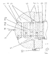
Fig. 1 zeigt einen Ausschnitt eines erfindungsgemäßen Kopfes in einer Schnittdarstellung, -
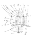
Fig. 2 zeigt den Ausschnitt ausFig. 1 , wobei der bewegliche Dorn 1 gegenüberFig. 2 verschoben ist, -
Fig. 3 zeigt beispielhaft eine Querschnittsfläche eines Oberflächenbereichs zur Herstellung eines rechteckigen Kanisters, und -
Fig. 4 zeigt beispielhaft eine Querschnittsfläche eines Oberflächenbereichs zur Herstellung einer runden Flasche, die an einer Stelle eine Ausgussöffnung besitzt - Wie in
Fig. 1 dargestellt besitzt der Extrusionskopf ein erstes Kopfteil, nämlich einen Dorn 1, und ein zweites Kopfteil, nämlich eine Düse 2, die einen Fließkanal 3 begrenzen. Die Kopfgeometrie bzw. die Formgebung des zwischen der Düse und dem Dorn befindlichen ringförmigen Fließkanals 3 kann, wie es in der Regel der Fall ist, näherungsweise rund sein, wobei der Dorn 1 mittig in der Düse 2 positioniert ist. Der Dorn 1 und die Düse 2 haben somit eine identische Mittelinie M. Natürlich können die Düse 2 und oder der Dorn 1 auch jede andere Geometrie, wie zum Beispiel eine quadratische, eine rechteckige, eine ovale Geometrie oder aber auch eine andere punktsymmetrische Geometrie besitzen. - Die Düse 2 ist fest mit einem in
Fig. 1 nicht dargestellten Extruder verbunden, während der Dorn 1 sich relativ zu der feststehenden Düse 2 verschieben lässt. Der Dorn 1 und die Düse 2 weisen in einem Austrittsbereich A des Kopfes jeweils mindestens einen Kopfabschnitt auf, der eine innerhalb des Kopfabschnitts gleichbleibende Querschnittsfläche besitzt. Der Dorn 1 weist mindestens zwei Kopfabschnitte B, C, D, oder G auf, die innerhalb des betreffenden Kopfabschnitts B, C, D oder G eine gleichbleibende Geometrie aufweisen, deren Querschnittsfläche sich aber von der Querschnittfläche eines benachbarten Kopfabschnittes C, B, G oder D unterscheidet. Die axiale Länge eines jeden Kopfabschnitts B, C, D oder G sollte mindestens 2 mm betragen, vorzugsweise sogar mehr als 5 mm, damit der Kopfabschnitt B, C, D oder G eine ausreichende Wirkung auf den Fließwiderstand der durch den betreffenden Kopfabschnitt B, C, D oder G vorbeiströmenden Masse besitzt. - Um die Optimierung der Fließkanalgeometrie zu erleichtern, kann es vorteilhaft sein, wenn der Dorn 1 aus einzelnen Scheiben zusammengesetzt ist, so dass bei der Optimierung der Oberflächengeometrie des Dorns 1 eventuell nur eine einzelne Scheibe ausgetauscht werden kann und nicht immer gleich der komplette Dorn 1 ausgewechselt werden muss.
- Da bei dem erfindungsgemäßen Extrusionskopf der Dorn 1 in Extremfällen sehr weit und auch sehr schnell verfahren werden muss, sollte die Querschnittsfläche der Öffnung F der Dornführung 4 idealerweise gleich der Querschnittsfläche des Kopfabschnitts C sein, oder sich aber maximal um 15 Prozent davon unterscheiden. Nur so kann vermieden werden, dass sich beim Verfahren das Fließkanalvolumen im Kopf nicht in größerem Maß ändert, was bei einem konstanten Massestrom, der von dem Extruder ausgestoßen wird, automatisch zu einer störenden Änderung der Austrittsgeschwindigkeit v des Schlauchs 11 führen würde. Das gilt in gleicher Weise natürlich auch für die Düse bei den Köpfen, bei denen nicht der Dorn sondern die Düse verfahren wird. Im Folgenden wird aus Gründen der Vereinfachung nur noch der Fall des beweglichen Dorns 1 beschrieben. Alle aufgeführten Argumente gelten sinngemäß natürlich auch für den Fall, dass die Düse 2 und nicht der Dorn 1 verfahren wird.
- Bei Speicherköpfen ist es notwendig, dass der Austrittsspalt s des Fließkanals 3 am Austrittsbereich des Extrusionskopfs geschlossen ist, wenn der Speicher mit Schmelze gefüllt wird. Deswegen benötigt der axial verschiebbare Dorn 1 am Ende einen kurzen konischen Dornbereich 8. Zum Schließen wird der Dorn 1 so weit hochgefahren, bis das Ende dieses konischen Dornbereichs 8 die Düse 2 berührt. Zum Ausstoßen der Schmelze wird, wie in
Fig. 1 dargestellt, der Dorn 1 um ein Stück heruntergefahren, so dass sich am Dornende 8 ein Austrittsspalt s des Fließkanals 3 ergibt, der durch die Position des Dorns 1 genau vorgegeben ist. Dieser Austrittsspalt s kann nun über dem Umfang in starkem Maß variieren, je nachdem, ob in dem Dornbereich, der sich gerade am Düsenende befindet, lokale Profilierungen 6 vorhanden sind, oder ob die Mittellinie Mg des Kopfabschnitts G nicht mit der Mittellinie des Extrusionskopfes übereinstimmt. - Der für das Verfahren erforderliche Verfahrweg 9 des Dorns 1, der den Austrittsbereich A definiert, ist im Allgemeinen deutlich größer als bei konventionellen Blasverfahren. Er sollte bei kleinen Extrusionsköpfen im Minimum größer als 1 mm sein und bei großen Extrusionsköpfen im Maximum bis 100 mm oder mehr betragen können, um damit möglichst viele unterschiedliche Fließkanalbereiche bzw. Kopfabschnitte B, C, D oder G wirksam oder unwirksam werden zu lassen. Um sicherzustellen, dass die Schmelze auch bei Ausnutzung des maximalen Verfahrwegs 9, das heißt auch noch bei einem sehr weit herausgefahrenen Dorn 1 über das konische Dornende 8 gleitet, kann es vorteilhaft sein, das konische Dornende 8 aus Teflon herzustellen, oder aber zumindest die Oberfläche des konischen Dornabschnitts 8 mit einer Schicht zu versehen, die das Gleiten fördert.
- Bei Anlagen, die keinen Speicherkopf besitzen, und die deshalb den Schlauch 11 kontinuierlich ausstoßen, ist das kurze konische Dornende 8 natürlich nicht erforderlich, da der Austrittsspalt s des Fließkanals 3 zu keinem Zeitpunkt geschlossen werden muss. Um nun die Wanddicke des Schlauchs 11 entsprechend den jeweiligen lokalen Verstreckgraden, die das Formteil besitzt, über der Länge und über dem Umfang gezielt verändern zu können, verfügt der Dorn 1 über mindestens zwei Kopfabschnitte B und C mit einer jeweils innerhalb des Kopfabschnitts B, bzw. C gleichbleibenden Querschnittsfläche, wobei die Querschnittsflächen der Kopfabschnitte B und C voneinander abweichen. Auf diese Weise kann man es erreichen, dass die Austrittsgeschwindigkeit v des Schlauchs 11 über dem Umfang gleich ist, obwohl der durch den jeweiligen Kopfabschnitt B oder C gebildete Austrittsspalt s des Fließkanals 3 am Ende einer Düse 1 über dem Umfang unterschiedlich groß ist.
- Idealerweise besitzen die beiden Kopfteile im Austrittsbereich A mindestens je einen Oberflächenbereich bzw. Kopfabschnitt C und E, die näherungsweise zylindrisch sind.
- Um an jeder Stelle über dem Umfang des Extrusionskopfes immer die gleiche Masseaustrittsgeschwindigkeit v zu erreichen, kann es notwendig sein, dass der Dorn 1 mindestens einen Kopfabschnitt B besitzt, dessen mittlerer Abstand von der Mittellinie M des Kopfes größer ist und mindestens einen Kopfabschnitt G besitzt, dessen mittlerer Abstand von der Mittellinie M kleiner ist als der eines dritten Kopfabschnitts C. In vielen Fällen ist es auch vorteilhaft, wenn das bewegliche Kopfteil im Austrittsbereich A wenigstens zwei Kopfabschnitte B und G aufweist, deren Mittellinien Mg oder M eine andere Lage besitzen. Der Abstand der Mittellinien sollte bei kleinen Extrusionsköpfen mindestens 0,1 mm betragen, bei großen Extrusionsköpfen kann er größer als 10 mm sein. Der Dorn 1 kann auch sehr kleine lokal begrenzte Profilierungen 6 enthalten. Damit kann dann die Wanddicke des Schlauchs 11 auf einem über dem Umfang sehr kleinen Bereich verändert werden, um sehr lokal begrenzten Unterschieden in den Verstreckgraden im Hohlkörper gerecht zu werden. Bei komplizierten Geometrien des aus einem extrudierten Schlauchabschnitt hergestellten Hohlkörpers kann es notwendig werden, dass ein Dornabschnitt B, C, D, G über mindestens 30 Prozent seines Umfangs eine von der kreisförmigen Grundgeometrie abweichende, unregelmäßige, Geometrie besitzt.
- Zur Reduzierung von Unterschieden in der Austrittsgeschwindigkeit des Schlauchs 11 über dem Umfang kann es weiterhin sehr vorteilhaft sein, wenn der Dorn 1 mindestens einen exzentrischen Fließkanalabschnitt G besitzt, der sich außerhalb des Austrittsbereichs A des Extrusionskopfes befindet, und der erst durch eine Verschiebung des Dorns 1 in den Austrittsbereich A gelangt. Die Geometrie dieses Fließkanalabschnitts G muss dann wiederum so mit der Geometrie des Dornbereichs, der sich bei der entsprechenden Dornposition noch im Austrittsbereich A befindet, abgestimmt werden, dass sich trotz eines stark variierenden Austrittsspalts s des Fließkanals 3 wiederum gleiche Fließgeschwindigkeiten v über dem Umfang ergeben.
- Die Möglichkeiten zur gezielten Wanddickenprofilierung des Schlauchs 11 werden enorm erweitert, wenn die Düse 2 in axialer Richtung zweigeteilt ist und zwei Düsenteile 2A und 2B aufweist, und wenn sich zwischen den beiden Teilen 2A, 2B der Düse 2 ein elastisches Kippgelenk 5 befindet, das einerseits gegenüber der fließfähigen Masse abdichtet, das aber gleichzeitig zulässt, dass die beiden Teile 2A und 2B der Düse 2 geringfügig relativ zueinander verkippt werden können. In Verbindung mit einem Antrieb 10, mit dem die beiden Düsenteile 2A und 2B zueinander verkippt werden können, wird ein vorteilhaftes Blasformverfahren möglich, bei dem der Austrittsspalt s eines Fließkanals 3 eines Extrusionskopfes mit einem vorteilhaften parallelen oder nahezu parallelen Austrittsbereich A durch Kippen eines Düsenteils 2A, 2B und oder durch eine lokale Deformation der Düse 2 während des Austrags des Schlauchs 11 mit Hilfe von geeigneten Stellgliedern 10 verändert wird. Damit können dann Wanddickenprofilierungen in Austritts- und in Umfangsrichtung des Schlauchs 11 erreicht werden, die mit keinem bekannten Verfahren erreichbar sind. Somit kann die Wanddickenverteilung von Hohlkörpern, die extreme Unterschiede in den lokalen Verstreckverhältnissen besitzen, erheblich verbessert werden.
-
Fig. 3 zeigt nun beispielhaft eine Querschnittsfläche eines Kopfabschnitts eines Kopfteils, der geeignet ist zum Austrag eines Schlauchabschnitts, aus dem ein quadratischer Bereich eines Formkörpers hergestellt werden kann. Die Querschnittsflächen von Bereichen bzw. Kopfabschnitten, die sich oberhalb dieses Bereichs befinden, sollten nun eine solche Geometrie aufweisen, dass sich bei dem vorgegebenen Massedurchsatz zwar eine unterschiedliche Wanddicke ergibt, dass aber die Geschwindigkeit v des Schlauchaustrags über dem Umfang des Schlauchs möglichst konstant ist. -
Fig. 4 zeigt beispielsweise eine Querschnittsfläche eines Kopfabschnitts für einen runden Formkörperabschnitt, der an einer Stelle einen Ausguss oder einen Einfüllstutzen besitzt, in dessen Bereich der Verstreckgrad deutlich größer ist, als über dem restlichen Umfang des Formkörpers. Auch in diesem Fall muss natürlich der restliche Austrittsbereich A des Extrusionskopfes so gestaltet sein, dass die Austrittsgeschwindigkeit v des Schlauchs 11 über seinem Umfang möglichst konstant ist. Fährt man dann beispielsweise durch Verschieben einen ersten Kopfabschnitt des Dorns 1 aus dem Austrittsbereich A des Extruionskopfes heraus, verliert dieser Kopfabschnitt seinen Einfluss auf die Wanddickenverteilung des Schlauchs 11. Dafür kommt von oben ein neuer Kopfabschnitt in den Bereich des Austrittsspalts s des Extrusionskopfes, der dann die Verteilung der Schmelze stärker beeinflusst, als zu dem vorherigen Zeitpunkt, als er sich noch im Bereich H des Kopfes befunden hat, in dem der Fließkanal 3 viel größer ist als im Austrittsbereich A und insbesondere im Bereich des Austrittsspalts s.
Claims (11)
- Extrusionskopf für Kunststoffextruder, insbesondere zur Herstellung von Vorformlingen für geblasene Behälter, aufweisend zwei Kopfteile, wobei ein erstes Kopfteil ein Dorn (1) und ein zweites Kopfteil eine Düse (2) ist, und wobei die beiden Kopfteile in axialer Richtung über einen Austrittsbereich (A) hinweg relativ zueinander verlagerbar sind, wodurch die Geometrie eines Austrittsspalts s eines Fließkanals (3), der sich zwischen dem Dorn (1) und der Düse (2) befindet, und damit auch die Wanddicke eines aus dem Extrusionskopf austretenden schlauchförmigen Kunststoffstrangs (11) veränderbar ist, wobei jedes Kopfteil im Austrittsbereich (A) des Extrusionskopfes mindestens einen Kopfabschnitt mit einer gleichbleibenden Querschnittsfläche aufweist und dass mindestens ein Kopfteil mindestens zwei Kopfabschnitte (B) und (C) aufweist, die jeweils eine innerhalb des Kopfabschnitts (B), (C) gleichbleibende Querschnittsfläche besitzen, die axial voneinander beabstandet sind und die eine voneinander abweichende Querschnittsfläche aufweisen, dadurch gekennzeichnet, dass sich die Querschnittsfläche der Öffnung (F) der Führung eines beweglichen Kopfteils von der Querschnittsfläche des Endbereichs des beweglichen Kopfteils um weniger als 10% unterscheiden, so dass bei einem Verschieben des beweglichen Kopfteils keine Unstetigkeit in der mittleren Austrittsgeschwindigkeit des aus dem Extrusionskopf austretenden schlauchförmigen Kunststoffstrangs (11) auftritt.
- Extrusionskopf nach Anspruch 1, dadurch gekennzeichnet, dass mindestens bei einem Kopfteil die Querschnittsflächen am Anfang und am Ende des Austrittsbereichs (A) annähernd gleich sind.
- Extrusionskopf nach einem der vorgenannten Ansprüche, dadurch gekennzeichnet dass der Extrusionskopf im Austrittsbereich (A) mindestens einen Kopfabschnitt (B) besitzt, dessen mittlerer Abstand der Oberfläche von der Mittellinie (M) des Extrusionskopfes größer und mindestens einen Kopfabschnitt (G) besitzt, dessen mittlerer Abstand von der Mittellinie (M) kleiner ist als der eines dritten Kopfabschnitts (C).
- Extrusionskopf nach einem der vorgenannten Ansprüche, dadurch gekennzeichnet, dass der bewegliche Kopfteil im Austrittsbereich (A) wenigstens zwei Abschnitte (B) und (G) aufweist, deren Mittellinie (Mg) oder (M) eine unterschiedliche Lage besitzen.
- Extrusionskopf nach einem der vorgenannten Ansprüche, dadurch gekennzeichnet, dass der bewegliche Kopfteil (2) oder (3) mindestens einen Kopfabschnitt (G) besitzt, dessen Mittellinie (Mg) wenigstens einen Abstand von 0,1 mm von der Mittellinie (M) des Kopfteils (2) oder (3) besitzt.
- Extrusionskopf nach einem der vorgenannten Ansprüche, dadurch gekennzeichnet, dass das bewegliche Kopfteil im Austrittsbereich (A) über wenigstens einen Kopfabschnitt (G) verfügt, in dem mindestens ein Bereich (6) existiert, der eine von der kreisförmigen Geometrie abweichende, punktsymmetrische, Geometrie besitzt.
- Extrusionskopf nach einem der vorgenannten Ansprüche, dadurch gekennzeichnet, dass der bewegliche Kopfteil mindestens einen Kopfabschnitt (D) besitzt, dessen Mittellinie (Md) nicht die gleiche Lage besitzt, wie die Mittellinie (M) des Extrusionskopfes und der erst durch eine Verschiebung des beweglichen Kopfteils in den Austrittsbereich (A) des Extrusionskopfes gelangt.
- Extrusionskopf nach einem der vorgenannten Ansprüche, dadurch gekennzeichnet, dass das Ende des bewegliche Kopfteils aus Teflon besteht.
- Extrusionskopf nach einem der vorgenannten Ansprüche, dadurch gekennzeichnet, dass die Düse (2) zweigeteilt ist, und dass sich zwischen den beiden Düsenteilen (2A) und (2B) ein elastisches Kippgelenk (5) befindet, mit dem ein Düsenteil (2A), (2B) relativ zum anderen Düsenteil (2B), (2A) gekippt werden kann.
- Extrusionskopf nach einem der vorgenannten Ansprüche, dadurch gekennzeichnet, dass der Extrusionskopf zum Anflanschen der Düse (2) einen Bajonettverschluss besitzt.
- Extrusionskopf nach einem der vorgenannten Ansprüche, dadurch gekennzeichnet, dass der Austrittsspalt (s) am Ende des Austrittsbereich (A) des Fließkanals (3) eine ovale, eine rechteckige oder eine andere punktsymmetrische Querschnittsgeometrie besitzt.
Applications Claiming Priority (2)
| Application Number | Priority Date | Filing Date | Title |
|---|---|---|---|
| DE102011116680A DE102011116680A1 (de) | 2011-10-21 | 2011-10-21 | 3-D-Kopf |
| PCT/EP2012/070834 WO2013057304A1 (de) | 2011-10-21 | 2012-10-21 | Extrusionskopf und verfahren zur herstellung von hohlkörpern |
Publications (2)
| Publication Number | Publication Date |
|---|---|
| EP2768653A1 EP2768653A1 (de) | 2014-08-27 |
| EP2768653B1 true EP2768653B1 (de) | 2016-07-20 |
Family
ID=47143865
Family Applications (1)
| Application Number | Title | Priority Date | Filing Date |
|---|---|---|---|
| EP12783167.5A Active EP2768653B1 (de) | 2011-10-21 | 2012-10-21 | Extrusionskopf zur herstellung von hohlkörpern |
Country Status (7)
| Country | Link |
|---|---|
| US (1) | US9676134B2 (de) |
| EP (1) | EP2768653B1 (de) |
| CN (1) | CN104010791B (de) |
| DE (1) | DE102011116680A1 (de) |
| ES (1) | ES2599706T3 (de) |
| PL (1) | PL2768653T3 (de) |
| WO (1) | WO2013057304A1 (de) |
Cited By (1)
| Publication number | Priority date | Publication date | Assignee | Title |
|---|---|---|---|---|
| DE102018204729A1 (de) | 2018-03-28 | 2019-10-02 | Raumedic Ag | Werkzeugkopf für einen Hohlprofil-Extruder |
Families Citing this family (1)
| Publication number | Priority date | Publication date | Assignee | Title |
|---|---|---|---|---|
| DE102015224834B4 (de) * | 2015-12-10 | 2021-06-17 | Airbus Defence and Space GmbH | Extrusionsvorrichtung und Verfahren zum Auffüllen einer Nut mit einer Füllmasse |
Family Cites Families (15)
| Publication number | Priority date | Publication date | Assignee | Title |
|---|---|---|---|---|
| DE1704791B2 (de) * | 1968-03-18 | 1976-07-29 | Kautex Werke Reinold Hagen Gmbh, 5300 Bonn-Holzlar | Vorrichtung zum herstellen von im querschnitt ringfoermigen koerpern aus thermoplastischem kunststoff |
| DE7005561U (de) | 1970-02-17 | 1975-02-13 | Schloemann Siemag Ag | Spritzkopf zum spritzformen von kunststoffhohlprofilen |
| US3981672A (en) * | 1973-03-05 | 1976-09-21 | Phillips Petroleum Company | Apparatus for forming a parison |
| DE2654001C2 (de) * | 1976-11-27 | 1986-02-06 | Harald 5210 Troisdorf Feuerherm | Vorrichtung zum Herstellen von aus thermoplastischem Kunstoff bestehenden Hohlkörpern |
| DE2941260A1 (de) | 1979-10-09 | 1981-05-14 | Bell Maschinenfabrik Ag, Kriens | Extruderkopf |
| DE3026822C2 (de) * | 1980-07-16 | 1985-02-21 | Reiner Dipl.-Ing. 5205 St.Augustin Kader | Winkelspritzkopf zum Herstellen eines Schlauches |
| JPS6056515A (ja) | 1983-09-07 | 1985-04-02 | Showa Denko Kk | ブロ−成形用ダイ |
| JPS61175008A (ja) | 1985-01-31 | 1986-08-06 | Ishikawajima Harima Heavy Ind Co Ltd | ブロ−成形装置におけるバリソンの肉厚制御装置 |
| DE3639273A1 (de) * | 1986-11-17 | 1988-05-26 | Krauss Maffei Ag | Schlauchkopf fuer das extrudieren von schlaeuchen |
| JP3118097B2 (ja) | 1992-09-07 | 2000-12-18 | 昭和電工株式会社 | パリソンの肉厚調整のためのダイ |
| DE19818519C2 (de) * | 1998-03-27 | 2001-01-25 | Harald Feuerherm | Verfahren zum Extrusionsblasformen von Hohlkörpern und Strangpreßkopf zur Durchführung der Verfahrens |
| DE19903084C2 (de) | 1999-01-27 | 2001-01-25 | Harald Feuerherm | Strangpreßkopf zum Extrusionsblasformen von Kunststoffbehältern |
| DE19931870C2 (de) | 1999-07-09 | 2003-10-30 | Harald Feuerherm | Strangpreßkopf zum Extrusionsblasformen von Kunststoffbehältern |
| ITMI20050110A1 (it) | 2005-01-27 | 2006-07-28 | Uniloy Milacron S R L | Tsta di estrusione per il soffiaggio di corpi cavi con sistema di distribuzione dello spessore delle pareti del parison |
| MX2009000946A (es) | 2006-07-25 | 2009-03-23 | Uniloy Milacron S R L | Cabeza de extrusion para moldeo por soplado de cuerpos huecos con un sistema de distribucion del espesor de las paredes de la preforma. |
-
2011
- 2011-10-21 DE DE102011116680A patent/DE102011116680A1/de not_active Withdrawn
-
2012
- 2012-10-21 PL PL12783167T patent/PL2768653T3/pl unknown
- 2012-10-21 WO PCT/EP2012/070834 patent/WO2013057304A1/de not_active Ceased
- 2012-10-21 US US14/353,037 patent/US9676134B2/en active Active
- 2012-10-21 CN CN201280063384.0A patent/CN104010791B/zh not_active Expired - Fee Related
- 2012-10-21 EP EP12783167.5A patent/EP2768653B1/de active Active
- 2012-10-21 ES ES12783167.5T patent/ES2599706T3/es active Active
Cited By (1)
| Publication number | Priority date | Publication date | Assignee | Title |
|---|---|---|---|---|
| DE102018204729A1 (de) | 2018-03-28 | 2019-10-02 | Raumedic Ag | Werkzeugkopf für einen Hohlprofil-Extruder |
Also Published As
| Publication number | Publication date |
|---|---|
| WO2013057304A1 (de) | 2013-04-25 |
| CN104010791B (zh) | 2016-12-07 |
| ES2599706T3 (es) | 2017-02-02 |
| PL2768653T3 (pl) | 2017-01-31 |
| US9676134B2 (en) | 2017-06-13 |
| EP2768653A1 (de) | 2014-08-27 |
| US20140333014A1 (en) | 2014-11-13 |
| DE102011116680A1 (de) | 2013-04-25 |
| CN104010791A (zh) | 2014-08-27 |
Similar Documents
| Publication | Publication Date | Title |
|---|---|---|
| EP1060067B1 (de) | Extrusionskopf | |
| DE3043228C2 (de) | ||
| EP0486636B1 (de) | Speicherkopf für eine blasformmaschine | |
| EP1023984B1 (de) | Strangpresskopf zum Extrusionsblasformen von Kunststoffbehältern | |
| DE102013105749B4 (de) | Extrusionsschlauchkopf für diskontinuierliches Schäumen | |
| DE3632225A1 (de) | Verfahren und vorrichtung zur herstellung von rippenflanschrohren | |
| EP1066948B1 (de) | Strangpresskopf zum Extrusionsblasformen von Kunststoffbehältern | |
| DE112012006895B4 (de) | Mischkopf | |
| DE102007025296B4 (de) | Einrichtung zum Extrusionsblasformen von Kunststoffartikeln sowie Verfahren zur Herstellung eines Kunststoffartikels | |
| DE3939714A1 (de) | Schlauch | |
| EP1082204B2 (de) | Verfahren und vorrichtung zur herstellung von kunststoff-hohlkörpern | |
| DE3439285A1 (de) | Verfahren und vorrichtung zum herstellen eines hohlen kunststoffkoerpers | |
| EP2768653B1 (de) | Extrusionskopf zur herstellung von hohlkörpern | |
| DE1261657B (de) | Spritzkopf zum Herstellen von schlauchfoermigen Straengen | |
| DE202007016630U1 (de) | Vorrichtung zur fortlaufenden Herstellung eines Verbundrohres mit Rohrmuffe | |
| EP3124199B1 (de) | Stufenlos einstellbare kalibrierhülse für extrudierte kunststoffrohre | |
| DE1288297B (de) | Extrusionseinrichtung zum Herstellen von Schlaeuchen aus thermoplastischem Material | |
| DE3301248C2 (de) | Strangpreßkopf | |
| DE2537915B2 (de) | Misch- und Knetvorrichtung für eine Strangpresse zum Plastifizieren von thermoplastischen Kunststoffen | |
| CH432813A (de) | Verfahren und Vorrichtung zum Kühlen von rohrförmigen thermoplastischen Folien | |
| EP2153970B1 (de) | Verfahren zum Betreiben einer Extrusionslinie für Hohlprofile aus Kunststoff | |
| DE2911572C2 (de) | ||
| DE1234012B (de) | Spritzkopf einer Strangpresse | |
| DE1504472B2 (de) | ||
| AT304858B (de) | Spritzduese zur herstellung einer folie aus kunststoff |
Legal Events
| Date | Code | Title | Description |
|---|---|---|---|
| PUAI | Public reference made under article 153(3) epc to a published international application that has entered the european phase |
Free format text: ORIGINAL CODE: 0009012 |
|
| 17P | Request for examination filed |
Effective date: 20140521 |
|
| AK | Designated contracting states |
Kind code of ref document: A1 Designated state(s): AL AT BE BG CH CY CZ DE DK EE ES FI FR GB GR HR HU IE IS IT LI LT LU LV MC MK MT NL NO PL PT RO RS SE SI SK SM TR |
|
| DAX | Request for extension of the european patent (deleted) | ||
| 17Q | First examination report despatched |
Effective date: 20150605 |
|
| GRAP | Despatch of communication of intention to grant a patent |
Free format text: ORIGINAL CODE: EPIDOSNIGR1 |
|
| INTG | Intention to grant announced |
Effective date: 20160204 |
|
| GRAS | Grant fee paid |
Free format text: ORIGINAL CODE: EPIDOSNIGR3 |
|
| GRAA | (expected) grant |
Free format text: ORIGINAL CODE: 0009210 |
|
| AK | Designated contracting states |
Kind code of ref document: B1 Designated state(s): AL AT BE BG CH CY CZ DE DK EE ES FI FR GB GR HR HU IE IS IT LI LT LU LV MC MK MT NL NO PL PT RO RS SE SI SK SM TR |
|
| REG | Reference to a national code |
Ref country code: GB Ref legal event code: FG4D Free format text: NOT ENGLISH |
|
| REG | Reference to a national code |
Ref country code: CH Ref legal event code: EP |
|
| REG | Reference to a national code |
Ref country code: IE Ref legal event code: FG4D Free format text: LANGUAGE OF EP DOCUMENT: GERMAN |
|
| REG | Reference to a national code |
Ref country code: AT Ref legal event code: REF Ref document number: 813674 Country of ref document: AT Kind code of ref document: T Effective date: 20160815 |
|
| REG | Reference to a national code |
Ref country code: DE Ref legal event code: R096 Ref document number: 502012007731 Country of ref document: DE |
|
| REG | Reference to a national code |
Ref country code: LT Ref legal event code: MG4D |
|
| REG | Reference to a national code |
Ref country code: NL Ref legal event code: MP Effective date: 20160720 |
|
| REG | Reference to a national code |
Ref country code: FR Ref legal event code: PLFP Year of fee payment: 5 |
|
| PG25 | Lapsed in a contracting state [announced via postgrant information from national office to epo] |
Ref country code: FI Free format text: LAPSE BECAUSE OF FAILURE TO SUBMIT A TRANSLATION OF THE DESCRIPTION OR TO PAY THE FEE WITHIN THE PRESCRIBED TIME-LIMIT Effective date: 20160720 Ref country code: NL Free format text: LAPSE BECAUSE OF FAILURE TO SUBMIT A TRANSLATION OF THE DESCRIPTION OR TO PAY THE FEE WITHIN THE PRESCRIBED TIME-LIMIT Effective date: 20160720 Ref country code: RS Free format text: LAPSE BECAUSE OF FAILURE TO SUBMIT A TRANSLATION OF THE DESCRIPTION OR TO PAY THE FEE WITHIN THE PRESCRIBED TIME-LIMIT Effective date: 20160720 Ref country code: IS Free format text: LAPSE BECAUSE OF FAILURE TO SUBMIT A TRANSLATION OF THE DESCRIPTION OR TO PAY THE FEE WITHIN THE PRESCRIBED TIME-LIMIT Effective date: 20161120 Ref country code: NO Free format text: LAPSE BECAUSE OF FAILURE TO SUBMIT A TRANSLATION OF THE DESCRIPTION OR TO PAY THE FEE WITHIN THE PRESCRIBED TIME-LIMIT Effective date: 20161020 Ref country code: LT Free format text: LAPSE BECAUSE OF FAILURE TO SUBMIT A TRANSLATION OF THE DESCRIPTION OR TO PAY THE FEE WITHIN THE PRESCRIBED TIME-LIMIT Effective date: 20160720 Ref country code: HR Free format text: LAPSE BECAUSE OF FAILURE TO SUBMIT A TRANSLATION OF THE DESCRIPTION OR TO PAY THE FEE WITHIN THE PRESCRIBED TIME-LIMIT Effective date: 20160720 |
|
| PGFP | Annual fee paid to national office [announced via postgrant information from national office to epo] |
Ref country code: GB Payment date: 20161124 Year of fee payment: 5 Ref country code: FR Payment date: 20161124 Year of fee payment: 5 |
|
| REG | Reference to a national code |
Ref country code: ES Ref legal event code: FG2A Ref document number: 2599706 Country of ref document: ES Kind code of ref document: T3 Effective date: 20170202 |
|
| PG25 | Lapsed in a contracting state [announced via postgrant information from national office to epo] |
Ref country code: PT Free format text: LAPSE BECAUSE OF FAILURE TO SUBMIT A TRANSLATION OF THE DESCRIPTION OR TO PAY THE FEE WITHIN THE PRESCRIBED TIME-LIMIT Effective date: 20161121 Ref country code: GR Free format text: LAPSE BECAUSE OF FAILURE TO SUBMIT A TRANSLATION OF THE DESCRIPTION OR TO PAY THE FEE WITHIN THE PRESCRIBED TIME-LIMIT Effective date: 20161021 Ref country code: BE Free format text: LAPSE BECAUSE OF NON-PAYMENT OF DUE FEES Effective date: 20161031 Ref country code: SE Free format text: LAPSE BECAUSE OF FAILURE TO SUBMIT A TRANSLATION OF THE DESCRIPTION OR TO PAY THE FEE WITHIN THE PRESCRIBED TIME-LIMIT Effective date: 20160720 Ref country code: LV Free format text: LAPSE BECAUSE OF FAILURE TO SUBMIT A TRANSLATION OF THE DESCRIPTION OR TO PAY THE FEE WITHIN THE PRESCRIBED TIME-LIMIT Effective date: 20160720 |
|
| PGFP | Annual fee paid to national office [announced via postgrant information from national office to epo] |
Ref country code: ES Payment date: 20161124 Year of fee payment: 5 Ref country code: PL Payment date: 20161114 Year of fee payment: 5 Ref country code: IT Payment date: 20161117 Year of fee payment: 5 |
|
| REG | Reference to a national code |
Ref country code: DE Ref legal event code: R097 Ref document number: 502012007731 Country of ref document: DE |
|
| PG25 | Lapsed in a contracting state [announced via postgrant information from national office to epo] |
Ref country code: EE Free format text: LAPSE BECAUSE OF FAILURE TO SUBMIT A TRANSLATION OF THE DESCRIPTION OR TO PAY THE FEE WITHIN THE PRESCRIBED TIME-LIMIT Effective date: 20160720 Ref country code: RO Free format text: LAPSE BECAUSE OF FAILURE TO SUBMIT A TRANSLATION OF THE DESCRIPTION OR TO PAY THE FEE WITHIN THE PRESCRIBED TIME-LIMIT Effective date: 20160720 |
|
| PGFP | Annual fee paid to national office [announced via postgrant information from national office to epo] |
Ref country code: TR Payment date: 20161110 Year of fee payment: 5 |
|
| PLBE | No opposition filed within time limit |
Free format text: ORIGINAL CODE: 0009261 |
|
| STAA | Information on the status of an ep patent application or granted ep patent |
Free format text: STATUS: NO OPPOSITION FILED WITHIN TIME LIMIT |
|
| PG25 | Lapsed in a contracting state [announced via postgrant information from national office to epo] |
Ref country code: DK Free format text: LAPSE BECAUSE OF FAILURE TO SUBMIT A TRANSLATION OF THE DESCRIPTION OR TO PAY THE FEE WITHIN THE PRESCRIBED TIME-LIMIT Effective date: 20160720 Ref country code: CZ Free format text: LAPSE BECAUSE OF FAILURE TO SUBMIT A TRANSLATION OF THE DESCRIPTION OR TO PAY THE FEE WITHIN THE PRESCRIBED TIME-LIMIT Effective date: 20160720 Ref country code: SM Free format text: LAPSE BECAUSE OF FAILURE TO SUBMIT A TRANSLATION OF THE DESCRIPTION OR TO PAY THE FEE WITHIN THE PRESCRIBED TIME-LIMIT Effective date: 20160720 Ref country code: BG Free format text: LAPSE BECAUSE OF FAILURE TO SUBMIT A TRANSLATION OF THE DESCRIPTION OR TO PAY THE FEE WITHIN THE PRESCRIBED TIME-LIMIT Effective date: 20161020 Ref country code: SK Free format text: LAPSE BECAUSE OF FAILURE TO SUBMIT A TRANSLATION OF THE DESCRIPTION OR TO PAY THE FEE WITHIN THE PRESCRIBED TIME-LIMIT Effective date: 20160720 |
|
| 26N | No opposition filed |
Effective date: 20170421 |
|
| REG | Reference to a national code |
Ref country code: IE Ref legal event code: MM4A |
|
| PG25 | Lapsed in a contracting state [announced via postgrant information from national office to epo] |
Ref country code: LU Free format text: LAPSE BECAUSE OF NON-PAYMENT OF DUE FEES Effective date: 20161021 Ref country code: SI Free format text: LAPSE BECAUSE OF FAILURE TO SUBMIT A TRANSLATION OF THE DESCRIPTION OR TO PAY THE FEE WITHIN THE PRESCRIBED TIME-LIMIT Effective date: 20160720 |
|
| PG25 | Lapsed in a contracting state [announced via postgrant information from national office to epo] |
Ref country code: IE Free format text: LAPSE BECAUSE OF NON-PAYMENT OF DUE FEES Effective date: 20161021 |
|
| REG | Reference to a national code |
Ref country code: BE Ref legal event code: MM Effective date: 20161031 |
|
| PG25 | Lapsed in a contracting state [announced via postgrant information from national office to epo] |
Ref country code: HU Free format text: LAPSE BECAUSE OF FAILURE TO SUBMIT A TRANSLATION OF THE DESCRIPTION OR TO PAY THE FEE WITHIN THE PRESCRIBED TIME-LIMIT; INVALID AB INITIO Effective date: 20121021 |
|
| GBPC | Gb: european patent ceased through non-payment of renewal fee |
Effective date: 20171021 |
|
| PG25 | Lapsed in a contracting state [announced via postgrant information from national office to epo] |
Ref country code: MT Free format text: LAPSE BECAUSE OF FAILURE TO SUBMIT A TRANSLATION OF THE DESCRIPTION OR TO PAY THE FEE WITHIN THE PRESCRIBED TIME-LIMIT Effective date: 20160720 Ref country code: MC Free format text: LAPSE BECAUSE OF FAILURE TO SUBMIT A TRANSLATION OF THE DESCRIPTION OR TO PAY THE FEE WITHIN THE PRESCRIBED TIME-LIMIT Effective date: 20160720 Ref country code: MK Free format text: LAPSE BECAUSE OF FAILURE TO SUBMIT A TRANSLATION OF THE DESCRIPTION OR TO PAY THE FEE WITHIN THE PRESCRIBED TIME-LIMIT Effective date: 20160720 Ref country code: CY Free format text: LAPSE BECAUSE OF FAILURE TO SUBMIT A TRANSLATION OF THE DESCRIPTION OR TO PAY THE FEE WITHIN THE PRESCRIBED TIME-LIMIT Effective date: 20160720 |
|
| REG | Reference to a national code |
Ref country code: FR Ref legal event code: ST Effective date: 20180629 |
|
| PG25 | Lapsed in a contracting state [announced via postgrant information from national office to epo] |
Ref country code: GB Free format text: LAPSE BECAUSE OF NON-PAYMENT OF DUE FEES Effective date: 20171021 |
|
| PG25 | Lapsed in a contracting state [announced via postgrant information from national office to epo] |
Ref country code: FR Free format text: LAPSE BECAUSE OF NON-PAYMENT OF DUE FEES Effective date: 20171031 |
|
| PG25 | Lapsed in a contracting state [announced via postgrant information from national office to epo] |
Ref country code: AL Free format text: LAPSE BECAUSE OF FAILURE TO SUBMIT A TRANSLATION OF THE DESCRIPTION OR TO PAY THE FEE WITHIN THE PRESCRIBED TIME-LIMIT Effective date: 20160720 Ref country code: IT Free format text: LAPSE BECAUSE OF NON-PAYMENT OF DUE FEES Effective date: 20171021 |
|
| REG | Reference to a national code |
Ref country code: DE Ref legal event code: R079 Ref document number: 502012007731 Country of ref document: DE Free format text: PREVIOUS MAIN CLASS: B29C0047220000 Ipc: B29C0048325000 |
|
| REG | Reference to a national code |
Ref country code: ES Ref legal event code: FD2A Effective date: 20181221 |
|
| PG25 | Lapsed in a contracting state [announced via postgrant information from national office to epo] |
Ref country code: ES Free format text: LAPSE BECAUSE OF NON-PAYMENT OF DUE FEES Effective date: 20171022 |
|
| PG25 | Lapsed in a contracting state [announced via postgrant information from national office to epo] |
Ref country code: PL Free format text: LAPSE BECAUSE OF NON-PAYMENT OF DUE FEES Effective date: 20171021 |
|
| PGFP | Annual fee paid to national office [announced via postgrant information from national office to epo] |
Ref country code: AT Payment date: 20201117 Year of fee payment: 9 |
|
| REG | Reference to a national code |
Ref country code: AT Ref legal event code: MM01 Ref document number: 813674 Country of ref document: AT Kind code of ref document: T Effective date: 20211021 |
|
| PG25 | Lapsed in a contracting state [announced via postgrant information from national office to epo] |
Ref country code: TR Free format text: LAPSE BECAUSE OF NON-PAYMENT OF DUE FEES Effective date: 20171021 |
|
| PG25 | Lapsed in a contracting state [announced via postgrant information from national office to epo] |
Ref country code: AT Free format text: LAPSE BECAUSE OF NON-PAYMENT OF DUE FEES Effective date: 20211021 |
|
| PGFP | Annual fee paid to national office [announced via postgrant information from national office to epo] |
Ref country code: CH Payment date: 20221124 Year of fee payment: 11 |
|
| REG | Reference to a national code |
Ref country code: CH Ref legal event code: PL |
|
| PG25 | Lapsed in a contracting state [announced via postgrant information from national office to epo] |
Ref country code: CH Free format text: LAPSE BECAUSE OF NON-PAYMENT OF DUE FEES Effective date: 20231031 |
|
| PG25 | Lapsed in a contracting state [announced via postgrant information from national office to epo] |
Ref country code: CH Free format text: LAPSE BECAUSE OF NON-PAYMENT OF DUE FEES Effective date: 20231031 |
|
| PGFP | Annual fee paid to national office [announced via postgrant information from national office to epo] |
Ref country code: DE Payment date: 20251021 Year of fee payment: 14 |