EP2769607A1 - Side stabilizer for agricultural machines - Google Patents
Side stabilizer for agricultural machines Download PDFInfo
- Publication number
- EP2769607A1 EP2769607A1 EP14155310.7A EP14155310A EP2769607A1 EP 2769607 A1 EP2769607 A1 EP 2769607A1 EP 14155310 A EP14155310 A EP 14155310A EP 2769607 A1 EP2769607 A1 EP 2769607A1
- Authority
- EP
- European Patent Office
- Prior art keywords
- hollow body
- cylindrical element
- stabilizer
- locator
- cylindrical
- Prior art date
- Legal status (The legal status is an assumption and is not a legal conclusion. Google has not performed a legal analysis and makes no representation as to the accuracy of the status listed.)
- Granted
Links
Images


Classifications
-
- A—HUMAN NECESSITIES
- A01—AGRICULTURE; FORESTRY; ANIMAL HUSBANDRY; HUNTING; TRAPPING; FISHING
- A01B—SOIL WORKING IN AGRICULTURE OR FORESTRY; PARTS, DETAILS, OR ACCESSORIES OF AGRICULTURAL MACHINES OR IMPLEMENTS, IN GENERAL
- A01B59/00—Devices specially adapted for connection between animals or tractors and agricultural machines or implements
- A01B59/002—Details, component parts
- A01B59/004—Length-adjustable links
-
- A—HUMAN NECESSITIES
- A01—AGRICULTURE; FORESTRY; ANIMAL HUSBANDRY; HUNTING; TRAPPING; FISHING
- A01B—SOIL WORKING IN AGRICULTURE OR FORESTRY; PARTS, DETAILS, OR ACCESSORIES OF AGRICULTURAL MACHINES OR IMPLEMENTS, IN GENERAL
- A01B59/00—Devices specially adapted for connection between animals or tractors and agricultural machines or implements
- A01B59/04—Devices specially adapted for connection between animals or tractors and agricultural machines or implements for machines pulled or pushed by a tractor
- A01B59/041—Devices specially adapted for connection between animals or tractors and agricultural machines or implements for machines pulled or pushed by a tractor preventing or limiting side-play of implements
- A01B59/0415—Devices specially adapted for connection between animals or tractors and agricultural machines or implements for machines pulled or pushed by a tractor preventing or limiting side-play of implements by hydraulic or pneumatic means acting on the lower draft links
Definitions
- the present invention relates to a side stabilizer for agricultural machines.
- the three-point linkages have a pair of side arms movable between a work position, in which they are lowered to allow the use of the tools connected to them, and an idle position, in which they are raised with respect to the ground to facilitate the movement of the agricultural machine.
- the side arms must have a certain degree of freedom when they are in the lowered position, while they have to be rigidly connected to the rest of the structure when they are arranged in the raised position in order to avoid unwanted stress.
- stabilization devices which are connected on one side to the structure of the agricultural machine and on the other side to a corresponding side arm of the three-point linkage.
- the stabilizing elements generally comprise a hollow body, intended to be connected to the agricultural machine, and a cylindrical element, intended to be connected to one of said side arms and coupled to the hollow body in a sliding manner. Between the hollow body and the cylindrical element elastic means are also interposed able to apply a return force on the corresponding side arm, with the latter in the work position, to bring it to a predefined neutral position. Blocking means are also provided that can be operated to prevent or allow the relative shift of the hollow body and of the cylindrical element.
- the blocking means are generally of the mechanical type and are selectively movable between a blocking position and a floating position.
- a known stabilizer having blocking means of the mechanical type is described by EP 1342399 , which involves the use of a blocking member hinged at one end to the hollow body and having, at the opposite end, a pair of recesses able to cooperate with the respective protrusions defined on the cylindrical element. More in particular, such blocking member is movable between a blocking position, wherein it engages with the protrusions defined on the cylindrical element to prevent the shifts of the latter in both directions, and at least a floating position, wherein it is disengaged from the aforementioned protrusions and thus allows the cylindrical element to move with respect to the hollow body.
- This known stabilization device has a number of drawbacks.
- the stabilization device described above in fact, appears to be not easy to make and function due to the complex interrelationship between the elements that make it up.
- the hollow body, the cylindrical element and the blocking member must be made with precise machining tolerances in order to allow their mutual engagement in the different work positions and, therefore, the correct operation of the stabilization device itself.
- Still another drawback of the stabilization device described above consists in that it does not allow to flexibly adapt to different work conditions. This is due in particular to the fact that it has only two operating conditions, i.e., depending on the position of the blocking member it allows or prevents the relative movement of the stabilization elements.
- EP 1084601 An example of a known stabilization device comprising hydraulic blocking means is described by EP 1084601 which envisages the presence of a tubular locator element fitted sealed in the hollow body above and inside which the cylindrical element is housed sliding.
- the locator element which supports a pair of plates which engage with a lever associated with the cylindrical element to prevent the rotation of the latter around its own axis, protrudes from the open extremity of the hollow body and extends outwards.
- this type of stabilizer can not ensure the proper sealing over time of the pressurized chamber acting on the locator element. This is due to the fact that the lateral surface of the locator element is exposed to external agents that could damage it, thus jeopardizing the surface finish and, as a consequence, the correct coupling with the sealing members.
- the main aim of the present invention is to provide a side stabilizer for agricultural machines that allows to overcome the drawbacks of known devices.
- the present invention aims at providing a side stabilizer that, besides controlling the stop of the cylindrical element in a fluid-dynamic manner is also safer as far as operation is concerned with respect to the stabilizers of known type.
- an object of the present invention is to ensure, in use, the sealing between the blocking means of the position of the cylindrical element and the hollow body.
- Yet another object is to provide a side stabilizer for agricultural machines that have anti-rotation means of the cylindrical element with respect to the hollow body which are simpler to manufacture than those of known type.
- the stabilizer 1 comprises a hollow body 2 associable with the structure of an agricultural machine and a cylindrical element 3 associable with the lower arm B of a three-point linkage and fitted sliding within the hollow body 2.
- the hollow body 2 has an open extremity 2a, through which the cylindrical element 3 is fitted, and the opposite closed extremity 2b.
- the hollow body 2 also has connection means 40 for connecting to the structure of an agricultural machine not shown in the figures.
- the cylindrical element 3 is then movable with respect to the hollow body 2 along a direction of translation, identified in the figures by the double arrow 4.
- the direction of translation 4 corresponds to the longitudinal axis X of the cylindrical element 3.
- Figure 1 represents a pair of stabilizers 1 each of which is associated with a relative lower arm B.
- the operation of the stabilizers 1 is complementary, i.e. when one works under compression the other works under traction.
- the stabilizer 1 also comprises at least a locator element 5 fitted tight and mobile inside the hollow body 2 and the position of which is adjustable in a fluid-dynamic manner to define the end-of-stroke position of the cylindrical element 3 along at least one sense of the direction of translation 4. More in particular, according to the position of the locator element 5 the end-of-stroke position of the cylindrical element 3 is determined in the direction of insertion inside the hollow body 2. Since, as mentioned above, the stabilizers work in pairs, it is easy to understand that, by blocking each of them in the direction of insertion of the corresponding cylindrical element 3 the shift of the latter in both directions is prevented.
- the locator element 5 is placed between the closed extremity 2b and the cylindrical element 3 and delimits a thrust chamber 6 having a passage opening 7 for a work fluid.
- the locator element 5 is cup c-shaped and has a bottom wall 5a and a side wall 5b, where the latter cooperates with one or more sealing elements 8 associated with the inner wall of the hollow body 2. More particularly, the bottom wall 5a is turned towards the closed extremity 2b, the thrust chamber 6 being placed between them, and the cylindrical element 3 fits in the side wall 5b.
- the locator element 5 is movable between at least a floating position, wherein it is moved away from the cylindrical element 3 to allow the shift of the latter with respect to the hollow body 2, and at least a blocking position, wherein it is arranged in the proximity of the cylindrical element 3 to prevent it from shifting along the direction of translation 4 towards the inside of the hollow body 2.
- the cylindrical element 3 in the floating position the cylindrical element 3 can move along the direction of translation 4 in both senses, while in the blocking position it can only move in the away direction from the closed extremity 2b.
- the locator element 5 rests, in the floating position, with its bottom wall 5a against the closed extremity 2b of the hollow body 2.
- the locator element 5 can be moved at least in an intermediate position to the floating position and the blocking position.
- the shift of the locator element 5 between the work positions described above may be of the continuous or discreet type.
- the stabilizer 1 then comprises protection means 9 for protecting the locator element 5 which are placed between the hollow body 2 and the cylindrical element 3 so as to define a substantially closed chamber 30 (since it may be not sealed) inside which the locator element itself is contained.
- the protection means 9 comprise at least a protection element having a tubular conformation and fitted around the cylindrical element 3.
- the protection element 9 is integrally associated with the hollow body 2. More in particular, between the hollow body 2 and the protection element 9 is placed a first stop element 10, able to reciprocally bind them along a first sense of the direction of translation 4, and at least a second stop element 11, able to reciprocally bind them along the opposite sense of the direction of translation 4.
- the first and the second stop elements 10 and 11 are made up, e.g., of a toroidal elastic ring and of a Seeger ring, respectively.
- the protection element 9 covers substantially the entire portion 3a of the cylindrical element 3 fitted within the hollow body 2 in the predefined neutral position.
- the protection element 9 comprises a first portion 9a arranged in correspondence to the open extremity 2a and a second portion 9b that fits inside the locator element 5 and which has a smaller diameter than the first portion 9a.
- the extremity 3c of the cylindrical element 3 arranged inside the hollow body 2 protrudes slightly with respect to the extremity of the protection element 9.
- the first portion 9a of the protection element 9 defines a resting surface 9c of the locator element 5 and, in more detail, of the extremity surface 5c of the side wall 5b. As visible from Figure 4 , the extremity surface 5c is substantially parallel to the bottom wall 5a.
- the distance between the bottom wall 5a and the extremity 3c of the cylindrical element 3 is less than the distance between the extremity surface 5c and the resting surface 9c, so that in the blocking position the bottom wall 5a rests against the cylindrical element 3.
- the stabilizer 1 also comprises contrast means 14 for contrasting the shift of the cylindrical element 3. More in detail, the contrast means 14 are able to apply a return force on the cylindrical element 3 directed in a sense opposite its shift, so as to push it towards the predefined neutral position.
- the contrast means 14 are placed between the cylindrical element 3 and the protection element 9.
- the contrast means 14 comprise elastic means 15, e.g. composed of a helical spring fitted around a portion of the cylindrical element 3, the extremities of which press against respective stop rings, of which a first ring 16 and a second ring 17, sliding with respect to the cylindrical element itself. More in detail, the contrast means 14 also comprise a first and a second abutment surfaces integral with the cylindrical element 3 and able to drag the first and second rings 16 and 17 during the shift of the cylindrical element itself towards the inside and towards the outside, respectively, of the hollow body 2. In the embodiment shown in the figures, the first abutment surface is defined by a portion 3b of the cylindrical element 3 having greater diameter than the portion 3a and the second abutment surface is defined by a snap ring 18.
- the first and second rings 16 and 17 move therefore in the direction of mutual approaching/moving away as a result of the shift of the cylindrical element 3 along the direction of translation 4.
- the neutral position of the cylindrical element 3 corresponds therefore to the arrangement wherein the rings 16 and 17 are located at the maximum distance and the spring 15, which can be suitably pre-loaded, is in idle condition.
- the contrast means 14 may also comprise a tubular spacer element 19 associated with the second ring 17.
- the stabilizer 1 is sized in such a way that, with the locator element 5 in floating position, the stop of the cylindrical element 3 in the direction of insertion inside the hollow body 2 is defined by its extremity 3c resting on the bottom wall 5 a and not by the first ring 16 resting against the spacer element 19.
- the contact between the spacer element 19 and the first ring 16 defines on the contrary the stop of the cylindrical element 3 in the opposite direction, i.e. in the direction of moving away from the hollow body 2.
- the contrast means 14 also comprise a first and second end-of-stroke element 20 and 21 of the first and second ring 16 and 17 respectively along respective lines (opposite between them) of the direction of translation 4.
- the first and second end-of-stroke elements 20 and 21 are able to prevent the first ring 16 from being dragged by the cylindrical element 3 in its shift towards the outside of the hollow body 2 and the second ring 17 from being dragged by the cylindrical element 3 in its shift towards the inside of the hollow body 2, respectively.
- the protection element 9 integrally supports the first and second end-of-stroke elements 20 and 21. More particularly, the first and second end-of-stroke elements 20 and 21 are composed of respective toroidal elastic rings inserted in respective seats defined on the inner side surface of the protection element 9, with respect to which they protrude.
- the stabilizer 1 also comprises disposal means of the impurities that accumulate in the area 23 placed between the protection element 9 and the cylindrical element 3.
- impurities may be deposited e.g. on the outer surface of the cylindrical element 3 when the latter shifts towards the outside of the hollow body 2 and are then taken within the aforementioned area 23 following its return to the neutral position.
- the disposal means comprise at least one first through hole 22a, defined on the protection element 9 and communicating on one side with the area 23 and on the other side with the chamber 30, and a second through hole 22b, defined on the hollow body 2 and communicating on one side with the chamber 30 and on the other with the outside.
- the disposal means comprise a plurality of first holes 22a arranged along a circumference of the protection element 9 and spaced from one another. The impurities that accumulate in the area 23 are therefore disposed of outwards, passing in succession through the first and the second hole 22a and 22b.
- the cylindrical element 3 also has a threaded hole 24, facing outwards, wherein it is engaged by screwing the stem 25 which ends at the extremity with a connection member to the lower arm of a three-point linkage.
- the cylindrical element 3 is also movable in rotation around its longitudinal axis X with respect to the hollow body 2. By rotating the cylindrical element 3 with respect to the hollow body 2 it is therefore possible to adjust the position of the stem 25 with respect to the cylindrical element 3 and, therefore, the length of the stabilizer 1.
- the stabilizer 1 comprises anti-rotation means 26 able to prevent the accidental rotation, in use, of the cylindrical element 3 around the axis X.
- the anti-rotation means 26 comprise at least a lever 27 associated with the cylindrical element 3 and blocking means 28 associated with the outer surface of the hollow body 2 and able to prevent the rotation of the lever 27 around the longitudinal axis of the cylindrical element 3 .
- the lever 27 is hinged to an appendix 29 which projects radially outwardly from the cylindrical element 3 and is movable between a work configuration, wherein it is locked in rotation by the blocking means 28 (which still allow the shift of the cylindrical element itself along the direction of translation 4) and a rotation configuration, wherein it is released from the blocking means 28 to allow the rotation of the cylindrical element 3 around its own axis X.
- the blocking means 28 comprise at least a pair of blocking walls arranged on opposite sides of the lever 27, with the latter in the work position. This particular conformation of the blocking means 28 allows to avoid that the lever 27, generally consisting of a metal wire or the like folded on itself, is being extended following the contact with the blocking walls themselves.
- the position of the locator element 5 inside the chamber 30 shall be adjusted in a fluid-dynamic manner.
- the position of the locator element 5 may be adjusted e.g. by means of a fluid-dynamic circuit (not being part of the present invention) which can be connected to the passage opening 7 and to a sensor able to detect the lifting of the lower arm B of the three-point linkage.
- the fluid-dynamic circuit is then able to connect the passage opening 7 to a supply line of a work fluid under pressure or with a drain line.
- the cylindrical element 3 then moves towards the inside or towards the outside of the hollow body 2 depending on the force being applied on the stem 25.
- the shoulder defined by the portion 3b of the cylindrical element 3 drags in translation the first ring 16, while the second ring 17 remains stationary as a result of its resting against the second end-of-stroke element 21.
- the stop of the cylindrical element 3 in the direction of approaching the closed extremity 2b can be defined by the first ring 16 resting against the spacer element 19 or, preferably, by the extremity 3c resting against the bottom wall 5a.
- the snap ring 18 drags in translation the second ring 17, while the first ring 16 remains stationary due to its resting with the first end-of-stroke element 20.
- the stop of the cylindrical element 3 is defined by the spacer element 19 resting with the first ring 16.
- the protection element 9 remains stationary with respect to the hollow body 2, thus avoiding the side wall 5b, which cooperates with the sealing elements 8 to ensure the tightness of the thrust chamber 6, being accessible directly from the outside.
- the locator element 5 is thus completely contained within the chamber 30 both in floating position and in blocking position.
- the holes 22a and 22b allow the impurities or debris that collect in the area 23 to flow outside so as to ensure proper operation of the stabilizer 1 over time.
- the lever 27 is brought to the work configuration so as to prevent, through contact with the blocking walls 28, the rotation of the cylindrical element 3 with respect to the hollow body 2.
- the lever 27 is brought to the rotation configuration so as to be able to rotate the cylindrical element 3 around the axis X thus changing accordingly the position of the stem 25 within the hole 24.
- the conformation of the blocking plate allows to avoid that the rotation lever may become detached from the cylindrical element following the operation of the anti-rotation means.
Landscapes
- Life Sciences & Earth Sciences (AREA)
- Zoology (AREA)
- Engineering & Computer Science (AREA)
- Mechanical Engineering (AREA)
- Soil Sciences (AREA)
- Environmental Sciences (AREA)
- Fluid-Damping Devices (AREA)
- Steroid Compounds (AREA)
- Agricultural Machines (AREA)
- Vehicle Body Suspensions (AREA)
Abstract
a hollow body (2) open at one extremity (2a) and closed at the opposite extremity (2b) which is associable with the structure of an agricultural machine, a cylindrical element (3) fitted sliding inside the hollow body (2) along a direction of translation (4) and associable with the lower arm (B) of a three-point linkage, at least one locator element (5) fitted tight and mobile inside the hollow body (2) and the position of which is adjustable in a fluid-dynamic manner to adjust the end-of-stroke position of the cylindrical element (3) along at least one sense of the direction of translation (4), protection means (9) of the locator element (5) placed between said hollow body (2) and the cylindrical element (3) so as to define a substantially closed chamber (30) inside which the locator element itself is contained, wherein the protection means (9) comprise at least a protection element having a substantially tubular conformation and fitted the said cylindrical element (3) and where the protection element (9) is integrally associated with the hollow body (2).
Description
- The present invention relates to a side stabilizer for agricultural machines.
- In the field of agricultural machines the use is known of so-called three-point linkages to allow the attachment of tools or operating machines.
- The three-point linkages have a pair of side arms movable between a work position, in which they are lowered to allow the use of the tools connected to them, and an idle position, in which they are raised with respect to the ground to facilitate the movement of the agricultural machine.
- Generally, the side arms must have a certain degree of freedom when they are in the lowered position, while they have to be rigidly connected to the rest of the structure when they are arranged in the raised position in order to avoid unwanted stress.
- To meet these requirements stabilization devices are employed which are connected on one side to the structure of the agricultural machine and on the other side to a corresponding side arm of the three-point linkage.
- More in detail, the stabilizing elements generally comprise a hollow body, intended to be connected to the agricultural machine, and a cylindrical element, intended to be connected to one of said side arms and coupled to the hollow body in a sliding manner. Between the hollow body and the cylindrical element elastic means are also interposed able to apply a return force on the corresponding side arm, with the latter in the work position, to bring it to a predefined neutral position. Blocking means are also provided that can be operated to prevent or allow the relative shift of the hollow body and of the cylindrical element.
- The blocking means are generally of the mechanical type and are selectively movable between a blocking position and a floating position.
- A known stabilizer having blocking means of the mechanical type is described by
EP 1342399 , which involves the use of a blocking member hinged at one end to the hollow body and having, at the opposite end, a pair of recesses able to cooperate with the respective protrusions defined on the cylindrical element. More in particular, such blocking member is movable between a blocking position, wherein it engages with the protrusions defined on the cylindrical element to prevent the shifts of the latter in both directions, and at least a floating position, wherein it is disengaged from the aforementioned protrusions and thus allows the cylindrical element to move with respect to the hollow body. - This known stabilization device has a number of drawbacks.
- The stabilization device described above, in fact, appears to be not easy to make and function due to the complex interrelationship between the elements that make it up.
- More particularly, the hollow body, the cylindrical element and the blocking member must be made with precise machining tolerances in order to allow their mutual engagement in the different work positions and, therefore, the correct operation of the stabilization device itself.
- Still another drawback of the stabilization device described above consists in that it does not allow to flexibly adapt to different work conditions. This is due in particular to the fact that it has only two operating conditions, i.e., depending on the position of the blocking member it allows or prevents the relative movement of the stabilization elements.
- These drawbacks have been at least partly overcome by introducing hydraulically-operated blocking means.
- An example of a known stabilization device comprising hydraulic blocking means is described by
EP 1084601 which envisages the presence of a tubular locator element fitted sealed in the hollow body above and inside which the cylindrical element is housed sliding. - By hydraulically adjusting the position of the locator element, the end-of-stroke position of the cylindrical element fitted inside it is adjusted accordingly.
- The locator element, which supports a pair of plates which engage with a lever associated with the cylindrical element to prevent the rotation of the latter around its own axis, protrudes from the open extremity of the hollow body and extends outwards.
- Nevertheless, the stabilizer described by
EP 1084601 also has a number of drawbacks. - In particular, this type of stabilizer can not ensure the proper sealing over time of the pressurized chamber acting on the locator element. This is due to the fact that the lateral surface of the locator element is exposed to external agents that could damage it, thus jeopardizing the surface finish and, as a consequence, the correct coupling with the sealing members.
- Another drawback of the stabilizer known from
EP 1084601 consists in the complex manufacture of the anti-rotation means of the cylindrical element with respect to the hollow body. - The main aim of the present invention is to provide a side stabilizer for agricultural machines that allows to overcome the drawbacks of known devices. In particular, the present invention aims at providing a side stabilizer that, besides controlling the stop of the cylindrical element in a fluid-dynamic manner is also safer as far as operation is concerned with respect to the stabilizers of known type.
- Within this aim, an object of the present invention is to ensure, in use, the sealing between the blocking means of the position of the cylindrical element and the hollow body.
- Yet another object is to provide a side stabilizer for agricultural machines that have anti-rotation means of the cylindrical element with respect to the hollow body which are simpler to manufacture than those of known type.
- The above mentioned objects are achieved by the present side stabilizer for agricultural machines comprising:
- a hollow body open at one extremity and closed at the opposite extremity which is associable with the structure of an agricultural machine,
- a cylindrical element fitted sliding inside said hollow body along a direction of translation and associable with the lower arm of a three-point linkage,
- at least one locator element fitted tight and mobile inside said hollow body and the position of which is adjustable fluid-dynamically to adjust the end-of-stroke position of said cylindrical element along at least one sense of said direction of translation,
- characterized in that it comprises protection means of said locator element placed between said hollow body and said cylindrical element so as to define a substantially closed chamber inside which the locator element itself is contained.
- Other characteristics and advantages of the present invention will become more evident from the description of a preferred, but not exclusive, embodiment of a side stabilizer for agricultural machines, illustrated purely as an example but not limited to the annexed drawings in which:
-
Figure 1 is a schematic representation, in side elevation, of a pair of side stabilizers coupled to respective side arms of a three-point linkage; -
Figure 2 is an exploded view of a stabilizer according to the invention; -
Figure 3 is a top view of the stabilizer ofFigure 2 ; -
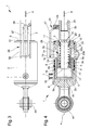
Figure 4 is a sectional view of the stabilizer ofFigure 2 ; -
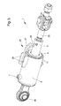
Figure 5 is an axonometric view of the stabilizer ofFigure 2 associated with the stem connecting to a lower arm of a three-point linkage. - With particular reference to such figures, globally indicated by 1 is a side stabilizer for agricultural machines.
- The stabilizer 1 comprises a
hollow body 2 associable with the structure of an agricultural machine and acylindrical element 3 associable with the lower arm B of a three-point linkage and fitted sliding within thehollow body 2. - More in detail, the
hollow body 2 has anopen extremity 2a, through which thecylindrical element 3 is fitted, and the opposite closedextremity 2b. - The
hollow body 2 also has connection means 40 for connecting to the structure of an agricultural machine not shown in the figures. - The portion of the
cylindrical element 3 that fits inside thehollow body 2 in a predefined neutral position, corresponding to the idle configuration of the stabilizer 1, is identified inFigure 4 with thereference number 3a. - The
cylindrical element 3 is then movable with respect to thehollow body 2 along a direction of translation, identified in the figures by thedouble arrow 4. The direction oftranslation 4 corresponds to the longitudinal axis X of thecylindrical element 3. -
Figure 1 represents a pair of stabilizers 1 each of which is associated with a relative lower arm B. As can easily be seen, the operation of the stabilizers 1 is complementary, i.e. when one works under compression the other works under traction. - The stabilizer 1 also comprises at least a
locator element 5 fitted tight and mobile inside thehollow body 2 and the position of which is adjustable in a fluid-dynamic manner to define the end-of-stroke position of thecylindrical element 3 along at least one sense of the direction oftranslation 4. More in particular, according to the position of thelocator element 5 the end-of-stroke position of thecylindrical element 3 is determined in the direction of insertion inside thehollow body 2. Since, as mentioned above, the stabilizers work in pairs, it is easy to understand that, by blocking each of them in the direction of insertion of the correspondingcylindrical element 3 the shift of the latter in both directions is prevented. - In the embodiment shown in the figures, the
locator element 5 is placed between the closedextremity 2b and thecylindrical element 3 and delimits a thrust chamber 6 having a passage opening 7 for a work fluid. - Preferably, the
locator element 5 is cup c-shaped and has abottom wall 5a and aside wall 5b, where the latter cooperates with one ormore sealing elements 8 associated with the inner wall of thehollow body 2. More particularly, thebottom wall 5a is turned towards the closedextremity 2b, the thrust chamber 6 being placed between them, and thecylindrical element 3 fits in theside wall 5b. - In use, the
locator element 5 is movable between at least a floating position, wherein it is moved away from thecylindrical element 3 to allow the shift of the latter with respect to thehollow body 2, and at least a blocking position, wherein it is arranged in the proximity of thecylindrical element 3 to prevent it from shifting along the direction oftranslation 4 towards the inside of thehollow body 2. - In other words, in the floating position the
cylindrical element 3 can move along the direction oftranslation 4 in both senses, while in the blocking position it can only move in the away direction from the closedextremity 2b. - In the embodiment shown in the figures, the
locator element 5 rests, in the floating position, with itsbottom wall 5a against the closedextremity 2b of thehollow body 2. - Suitably, the
locator element 5 can be moved at least in an intermediate position to the floating position and the blocking position. - Advantageously, the shift of the
locator element 5 between the work positions described above may be of the continuous or discreet type. - The stabilizer 1 then comprises protection means 9 for protecting the
locator element 5 which are placed between thehollow body 2 and thecylindrical element 3 so as to define a substantially closed chamber 30 (since it may be not sealed) inside which the locator element itself is contained. - The protection means 9 comprise at least a protection element having a tubular conformation and fitted around the
cylindrical element 3. - According to the invention, the
protection element 9 is integrally associated with thehollow body 2. More in particular, between thehollow body 2 and theprotection element 9 is placed afirst stop element 10, able to reciprocally bind them along a first sense of the direction oftranslation 4, and at least asecond stop element 11, able to reciprocally bind them along the opposite sense of the direction oftranslation 4. The first and thesecond stop elements - The
protection element 9 covers substantially theentire portion 3a of thecylindrical element 3 fitted within thehollow body 2 in the predefined neutral position. - As visible from
Figure 4 , theprotection element 9 comprises afirst portion 9a arranged in correspondence to theopen extremity 2a and asecond portion 9b that fits inside thelocator element 5 and which has a smaller diameter than thefirst portion 9a. - Suitably, the
extremity 3c of thecylindrical element 3 arranged inside thehollow body 2 protrudes slightly with respect to the extremity of theprotection element 9. - The
first portion 9a of theprotection element 9 defines a restingsurface 9c of thelocator element 5 and, in more detail, of theextremity surface 5c of theside wall 5b. As visible fromFigure 4 , theextremity surface 5c is substantially parallel to thebottom wall 5a. - Preferably, with the
locator element 5 in floating position, the distance between thebottom wall 5a and theextremity 3c of thecylindrical element 3 is less than the distance between theextremity surface 5c and the restingsurface 9c, so that in the blocking position thebottom wall 5a rests against thecylindrical element 3. - The stabilizer 1 also comprises contrast means 14 for contrasting the shift of the
cylindrical element 3. More in detail, the contrast means 14 are able to apply a return force on thecylindrical element 3 directed in a sense opposite its shift, so as to push it towards the predefined neutral position. - As visible from
Figure 4 , the contrast means 14 are placed between thecylindrical element 3 and theprotection element 9. - Suitably, the contrast means 14 comprise
elastic means 15, e.g. composed of a helical spring fitted around a portion of thecylindrical element 3, the extremities of which press against respective stop rings, of which afirst ring 16 and asecond ring 17, sliding with respect to the cylindrical element itself. More in detail, the contrast means 14 also comprise a first and a second abutment surfaces integral with thecylindrical element 3 and able to drag the first andsecond rings hollow body 2. In the embodiment shown in the figures, the first abutment surface is defined by aportion 3b of thecylindrical element 3 having greater diameter than theportion 3a and the second abutment surface is defined by asnap ring 18. - The first and
second rings cylindrical element 3 along the direction oftranslation 4. - The neutral position of the
cylindrical element 3 corresponds therefore to the arrangement wherein therings spring 15, which can be suitably pre-loaded, is in idle condition. - The contrast means 14 may also comprise a
tubular spacer element 19 associated with thesecond ring 17. - Preferably, the stabilizer 1 is sized in such a way that, with the
locator element 5 in floating position, the stop of thecylindrical element 3 in the direction of insertion inside thehollow body 2 is defined by itsextremity 3c resting on thebottom wall 5 a and not by thefirst ring 16 resting against thespacer element 19. The contact between thespacer element 19 and thefirst ring 16 defines on the contrary the stop of thecylindrical element 3 in the opposite direction, i.e. in the direction of moving away from thehollow body 2. - Advantageously, the contrast means 14 also comprise a first and second end-of-
stroke element second ring translation 4. As known to the technician in the sector, the first and second end-of-stroke elements first ring 16 from being dragged by thecylindrical element 3 in its shift towards the outside of thehollow body 2 and thesecond ring 17 from being dragged by thecylindrical element 3 in its shift towards the inside of thehollow body 2, respectively. - The
protection element 9 integrally supports the first and second end-of-stroke elements stroke elements protection element 9, with respect to which they protrude. - Advantageously, the stabilizer 1 also comprises disposal means of the impurities that accumulate in the
area 23 placed between theprotection element 9 and thecylindrical element 3. Such impurities may be deposited e.g. on the outer surface of thecylindrical element 3 when the latter shifts towards the outside of thehollow body 2 and are then taken within theaforementioned area 23 following its return to the neutral position. - The disposal means comprise at least one first through
hole 22a, defined on theprotection element 9 and communicating on one side with thearea 23 and on the other side with thechamber 30, and a second throughhole 22b, defined on thehollow body 2 and communicating on one side with thechamber 30 and on the other with the outside. Preferably, the disposal means comprise a plurality offirst holes 22a arranged along a circumference of theprotection element 9 and spaced from one another. The impurities that accumulate in thearea 23 are therefore disposed of outwards, passing in succession through the first and thesecond hole - The
cylindrical element 3 also has a threadedhole 24, facing outwards, wherein it is engaged by screwing thestem 25 which ends at the extremity with a connection member to the lower arm of a three-point linkage. Thecylindrical element 3 is also movable in rotation around its longitudinal axis X with respect to thehollow body 2. By rotating thecylindrical element 3 with respect to thehollow body 2 it is therefore possible to adjust the position of thestem 25 with respect to thecylindrical element 3 and, therefore, the length of the stabilizer 1. Suitably, the stabilizer 1 comprises anti-rotation means 26 able to prevent the accidental rotation, in use, of thecylindrical element 3 around the axis X. - The anti-rotation means 26 comprise at least a
lever 27 associated with thecylindrical element 3 and blocking means 28 associated with the outer surface of thehollow body 2 and able to prevent the rotation of thelever 27 around the longitudinal axis of thecylindrical element 3 . - More in detail, the
lever 27 is hinged to anappendix 29 which projects radially outwardly from thecylindrical element 3 and is movable between a work configuration, wherein it is locked in rotation by the blocking means 28 (which still allow the shift of the cylindrical element itself along the direction of translation 4) and a rotation configuration, wherein it is released from the blocking means 28 to allow the rotation of thecylindrical element 3 around its own axis X. - Preferably, the blocking means 28 comprise at least a pair of blocking walls arranged on opposite sides of the
lever 27, with the latter in the work position. This particular conformation of the blocking means 28 allows to avoid that thelever 27, generally consisting of a metal wire or the like folded on itself, is being extended following the contact with the blocking walls themselves. - The operation of the present invention is as follows.
- According to the particular working needs, the position of the
locator element 5 inside thechamber 30 shall be adjusted in a fluid-dynamic manner. The position of thelocator element 5 may be adjusted e.g. by means of a fluid-dynamic circuit (not being part of the present invention) which can be connected to thepassage opening 7 and to a sensor able to detect the lifting of the lower arm B of the three-point linkage. The fluid-dynamic circuit is then able to connect thepassage opening 7 to a supply line of a work fluid under pressure or with a drain line. - In the event of the
locator element 5 being arranged in floating position, i.e. with thebottom wall 5a resting against theclosed extremity 2b, thecylindrical element 3 is free to move in both senses of the direction oftranslation 4. - In such work condition, the
cylindrical element 3 then moves towards the inside or towards the outside of thehollow body 2 depending on the force being applied on thestem 25. - During the shift of the
cylindrical element 3 along the direction oftranslation 4, therings protection element 9. - More particularly, when the
cylindrical element 3 shifts from the neutral position towards theclosed extremity 2b, the shoulder defined by theportion 3b of thecylindrical element 3 drags in translation thefirst ring 16, while thesecond ring 17 remains stationary as a result of its resting against the second end-of-stroke element 21. As mentioned above, the stop of thecylindrical element 3 in the direction of approaching theclosed extremity 2b can be defined by thefirst ring 16 resting against thespacer element 19 or, preferably, by theextremity 3c resting against thebottom wall 5a. - During the return phase to the neutral position, the
first ring 16 moves away from thesecond ring 17, sliding with respect to thecylindrical element 3 and theprotection element 9, due to the thrust of thespring 15. - Similarly, when the
cylindrical element 3 moves away from theclosed extremity 2b, thesnap ring 18 drags in translation thesecond ring 17, while thefirst ring 16 remains stationary due to its resting with the first end-of-stroke element 20. In this case, the stop of thecylindrical element 3 is defined by thespacer element 19 resting with thefirst ring 16. - During the return phase to the neutral position, the
second ring 17 moves away from thefirst ring 16, sliding with respect to thecylindrical element 3 and theprotection element 9, due to the thrust of thespring 15. - During the operation of the stabilizer 1, the
protection element 9 remains stationary with respect to thehollow body 2, thus avoiding theside wall 5b, which cooperates with the sealingelements 8 to ensure the tightness of the thrust chamber 6, being accessible directly from the outside. Thelocator element 5 is thus completely contained within thechamber 30 both in floating position and in blocking position. - By changing the position of the
locator element 5 inside thechamber 30 the end-of-stroke position of thecylindrical element 3 changes accordingly in the direction of insertion within thehollow body 2, while the shift of the cylindrical element itself in the opposite direction remains unchanged. - In particular, when the
locator element 5 is brought to the blocking position, the shift of thelocator element 3 is restrained towards the inside of thehollow body 2. - When the
cylindrical element 3 is in extracted position with respect to thehollow body 2, at least a length of itsportion 3a is accessible from the outside, so that any impurities and debris can be deposited on it and thus be brought within thearea 23 following the return of thecylindrical element 3 in the neutral position. - In this case, the
holes area 23 to flow outside so as to ensure proper operation of the stabilizer 1 over time. - In use, the
lever 27 is brought to the work configuration so as to prevent, through contact with the blockingwalls 28, the rotation of thecylindrical element 3 with respect to thehollow body 2. - If, on the contrary, one wish to modify the length of the stabilizer 1, the
lever 27 is brought to the rotation configuration so as to be able to rotate thecylindrical element 3 around the axis X thus changing accordingly the position of thestem 25 within thehole 24. - It has in practice been ascertained how the described invention achieves the proposed objects and in particular the fact is underlined that the stabilizer according to the invention proves to be reliable in operation, since the presence of the protection element allows to avoid that the outer surface of the locator element can be subject to shock or damage during the working phases.
- In particular, by protecting the outer surface of the locator element the sealing with the hollow body is ensured.
- Furthermore, the presence of the disposal means of impurities ensure the proper and ready operation of the stabilizer even under particularly harsh working conditions.
- Moreover, the conformation of the blocking plate allows to avoid that the rotation lever may become detached from the cylindrical element following the operation of the anti-rotation means.
Claims (11)
- Side stabilizer (1) for agricultural machines comprising:a hollow body (2) open at one extremity (2a) and closed at the opposite extremity (2b) which is associable with the structure of an agricultural machine,a cylindrical element (3) fitted sliding inside said hollow body (2) along a direction of translation (4) and associable with the lower arm (B) of a three-point linkage,at least one locator element (5) fitted tight and mobile inside said hollow body (2) and the position of which is adjustable in a fluid-dynamic manner to adjust the end-of-stroke position of said cylindrical element (3) along at least one sense of said direction of translation (4),protection means (9) of said locator element (5) placed between said hollow body (2) and said cylindrical element (3) so as to define a substantially closed chamber (30) inside which the locator element itself is contained, wherein said protection means (9) comprise at least a protection element having a substantially tubular conformation and fitted around said cylindrical element (3) and characterized in that said protection element (9) is integrally associated with said hollow body (2).
- Stabilizer (1) according to claim 1, characterized in that said locator element (5) is placed between said hollow body (2) and said cylindrical element (3) and is substantially cup-shaped and in that said protection element (9) has a first portion (9a) arranged in correspondence to the open extremity (2a) of the hollow body (2) and at least a second portion (9b) fitted inside said locator element (5), said first portion (9a) having greater diameter than said second portion (9b).
- Stabilizer (1) according to claim 1 or 2, characterized in that said first portion (9a) defines a resting surface (9c) of said locator element (5).
- Stabilizer (1) according to one or more of the preceding claims, characterized in that it comprises contrast means (14) of the shift of said cylindrical element (3) with respect to said hollow body (2) which are placed between said protection element (9) and the cylindrical element itself.
- Stabilizer (1) according to claim 4, characterized in that said contrast means (14) comprise elastic means (15) the extremities of which press against respective stop rings (16, 17), said protection element (9) integrally supporting a first end-of-stroke element (20) for the shift of one of said stop rings (16, 17) along one sense of the direction of translation (4) and a second end-of-stroke element (21) of the other of said stop rings (17, 16) along the opposite sense.
- Stabilizer (1) according to one or more of the preceding claims, characterized in that said protection element (9) covers substantially the entire portion (3a) of said cylindrical element (3) contained inside said hollow body (2) in a neutral position.
- Stabilizer (1) according to one or more of the preceding claims, characterized in that it comprises disposal means (22) of the impurities which accumulate in the area (23) placed between said protection element (9) and said cylindrical element (3).
- Stabilizer (1) according to claim 9, characterized in that said disposal means (22) comprise at least a first through hole (22a), defined on said protection element (9) and communicating with said closed chamber (30), and at least a second through hole (22b), defined on said hollow body (2) and communicating, this too, with the closed chamber (30).
- Stabilizer (1) according to one or more of the preceding claims, characterized in that said locator element (5) can be moved between at least a floating position, wherein it is moved away from said cylindrical element (3) to allow the shift of the latter with respect to said hollow body (2), and a blocking position, wherein it is arranged in the proximity of said cylindrical element (3) to prevent it from shifting with respect to the hollow body (2).
- Stabilizer (1) according to one or more of the preceding claims, characterized in that, with said locator element (5) in floating position, the distance between the extremity surface (5c) of the side wall (5b) of the locator element itself and the resting surface (9c) defined by said protection element (9) is greater than the distance between the extremity (3c) of said cylindrical element (3) and the bottom wall (5a) of said locator element (5).
- Stabilizer (1) according to one or more of the preceding claims, characterized in that said cylindrical element (3) can be rotated with respect to said hollow body (2) around its longitudinal axis (X) and in that it comprises anti-rotation means (26) of the cylindrical element (3) itself which comprise at least a lever (27) connected to said cylindrical element (3) and blocking means associated with said hollow body (2) and able to prevent said lever (27) from rotating with respect to said longitudinal axis (X), said blocking means comprising a pair of blocking walls (28) arranged on opposite sides of the lever itself.
Applications Claiming Priority (1)
| Application Number | Priority Date | Filing Date | Title |
|---|---|---|---|
| IT000045A ITMO20130045A1 (en) | 2013-02-22 | 2013-02-22 | SIDE STABILIZER FOR AGRICULTURAL MACHINES |
Publications (2)
| Publication Number | Publication Date |
|---|---|
| EP2769607A1 true EP2769607A1 (en) | 2014-08-27 |
| EP2769607B1 EP2769607B1 (en) | 2017-06-28 |
Family
ID=48096042
Family Applications (1)
| Application Number | Title | Priority Date | Filing Date |
|---|---|---|---|
| EP14155310.7A Active EP2769607B1 (en) | 2013-02-22 | 2014-02-17 | Side stabilizer for agricultural machines |
Country Status (3)
| Country | Link |
|---|---|
| EP (1) | EP2769607B1 (en) |
| ES (1) | ES2640618T3 (en) |
| IT (1) | ITMO20130045A1 (en) |
Cited By (2)
| Publication number | Priority date | Publication date | Assignee | Title |
|---|---|---|---|---|
| EP3278644A1 (en) * | 2016-08-02 | 2018-02-07 | JRS GmbH & Co. KG | Stabiliser for a lower link |
| EP3295779A1 (en) * | 2016-09-20 | 2018-03-21 | Deere & Company | Upper guide for a three point power lift of an agricultural tractor |
Families Citing this family (1)
| Publication number | Priority date | Publication date | Assignee | Title |
|---|---|---|---|---|
| GB202413761D0 (en) * | 2024-09-18 | 2024-10-30 | Agco Int Gmbh | Adjustable end stop |
Citations (5)
| Publication number | Priority date | Publication date | Assignee | Title |
|---|---|---|---|---|
| EP0904680A1 (en) * | 1997-08-28 | 1999-03-31 | Rau Serta Hydraulik GmbH | Automatic stabilizing device for the two lower swing links of a connecting device of an implement to a tractor for agriculture or forestry |
| EP0998838A2 (en) * | 1998-11-04 | 2000-05-10 | CBM S.p.A. | A stabilizer for three-point hitches |
| EP1084601A1 (en) | 1999-09-17 | 2001-03-21 | GKN Walterscheid GmbH | Tractor lower hitch arm side strut |
| EP1084602A1 (en) * | 1999-09-17 | 2001-03-21 | GKN Walterscheid GmbH | Tractor lower arm side strut |
| EP1342399A1 (en) | 2002-03-04 | 2003-09-10 | CBM S.p.A. | A lateral stabilizer for lower arms of three-point hitches |
-
2013
- 2013-02-22 IT IT000045A patent/ITMO20130045A1/en unknown
-
2014
- 2014-02-17 EP EP14155310.7A patent/EP2769607B1/en active Active
- 2014-02-17 ES ES14155310.7T patent/ES2640618T3/en active Active
Patent Citations (5)
| Publication number | Priority date | Publication date | Assignee | Title |
|---|---|---|---|---|
| EP0904680A1 (en) * | 1997-08-28 | 1999-03-31 | Rau Serta Hydraulik GmbH | Automatic stabilizing device for the two lower swing links of a connecting device of an implement to a tractor for agriculture or forestry |
| EP0998838A2 (en) * | 1998-11-04 | 2000-05-10 | CBM S.p.A. | A stabilizer for three-point hitches |
| EP1084601A1 (en) | 1999-09-17 | 2001-03-21 | GKN Walterscheid GmbH | Tractor lower hitch arm side strut |
| EP1084602A1 (en) * | 1999-09-17 | 2001-03-21 | GKN Walterscheid GmbH | Tractor lower arm side strut |
| EP1342399A1 (en) | 2002-03-04 | 2003-09-10 | CBM S.p.A. | A lateral stabilizer for lower arms of three-point hitches |
Cited By (2)
| Publication number | Priority date | Publication date | Assignee | Title |
|---|---|---|---|---|
| EP3278644A1 (en) * | 2016-08-02 | 2018-02-07 | JRS GmbH & Co. KG | Stabiliser for a lower link |
| EP3295779A1 (en) * | 2016-09-20 | 2018-03-21 | Deere & Company | Upper guide for a three point power lift of an agricultural tractor |
Also Published As
| Publication number | Publication date |
|---|---|
| EP2769607B1 (en) | 2017-06-28 |
| ITMO20130045A1 (en) | 2014-08-23 |
| ES2640618T3 (en) | 2017-11-03 |
Similar Documents
| Publication | Publication Date | Title |
|---|---|---|
| EP2769607B1 (en) | Side stabilizer for agricultural machines | |
| US4191280A (en) | Mechanical link members | |
| US4646620A (en) | Automatic depth control system | |
| KR101335954B1 (en) | Joystice pilot valve with oil leakage prevention structure | |
| BRPI0813487B1 (en) | PROTECTOR FOR GAS CYLINDER ACTUATORS | |
| EP3292341B1 (en) | Female quick coupling engageable under pressure | |
| US20180274691A1 (en) | Valve having a control slide guided in a valve housing so as to be longitudinally movable | |
| EP1403102A1 (en) | Hitch device for attaching farm implements to a tractor and associated hydraulic circuit | |
| KR20150063407A (en) | Flow control valve for a hand held bidet shower | |
| EP3709785B1 (en) | Device for damping the inertial stresses | |
| JPS637722B2 (en) | ||
| US3963127A (en) | Blocking arrangement in hydraulically operated cranes | |
| JP5746281B2 (en) | Fluid pressure cylinder | |
| JP5308961B2 (en) | Fluid pressure cylinder | |
| KR101448429B1 (en) | Cylinder loaded type opening and shutting valve | |
| CN204533029U (en) | Bidirectional self-locking oil hydraulic cylinder | |
| EP2999915B1 (en) | A pressurizse fluid cylinder with a lever | |
| EP2345815B1 (en) | A hydraulic valve for supporting and controlling descent of a load | |
| CN104776078A (en) | Distributor with automatic restoring function for tractor | |
| US2678638A (en) | Fluid stop for fluid motors | |
| WO2020053893A1 (en) | Position and draft control mechanism for an implement coupled to vehicle hitch | |
| KR20160067458A (en) | Quick coupler for construction machinery having a safety device | |
| EP4230875A1 (en) | Double controlled centering electro-hydraulic lift-o-matic system | |
| US2960969A (en) | Adjustable depth control hydraulic cylinder stop mechanism | |
| GB1582259A (en) | Mechanical link members |
Legal Events
| Date | Code | Title | Description |
|---|---|---|---|
| PUAI | Public reference made under article 153(3) epc to a published international application that has entered the european phase |
Free format text: ORIGINAL CODE: 0009012 |
|
| 17P | Request for examination filed |
Effective date: 20140217 |
|
| AK | Designated contracting states |
Kind code of ref document: A1 Designated state(s): AL AT BE BG CH CY CZ DE DK EE ES FI FR GB GR HR HU IE IS IT LI LT LU LV MC MK MT NL NO PL PT RO RS SE SI SK SM TR |
|
| AX | Request for extension of the european patent |
Extension state: BA ME |
|
| R17P | Request for examination filed (corrected) |
Effective date: 20150213 |
|
| RBV | Designated contracting states (corrected) |
Designated state(s): AL AT BE BG CH CY CZ DE DK EE ES FI FR GB GR HR HU IE IS IT LI LT LU LV MC MK MT NL NO PL PT RO RS SE SI SK SM TR |
|
| GRAP | Despatch of communication of intention to grant a patent |
Free format text: ORIGINAL CODE: EPIDOSNIGR1 |
|
| STAA | Information on the status of an ep patent application or granted ep patent |
Free format text: STATUS: GRANT OF PATENT IS INTENDED |
|
| INTG | Intention to grant announced |
Effective date: 20170123 |
|
| GRAS | Grant fee paid |
Free format text: ORIGINAL CODE: EPIDOSNIGR3 |
|
| GRAA | (expected) grant |
Free format text: ORIGINAL CODE: 0009210 |
|
| STAA | Information on the status of an ep patent application or granted ep patent |
Free format text: STATUS: THE PATENT HAS BEEN GRANTED |
|
| AK | Designated contracting states |
Kind code of ref document: B1 Designated state(s): AL AT BE BG CH CY CZ DE DK EE ES FI FR GB GR HR HU IE IS IT LI LT LU LV MC MK MT NL NO PL PT RO RS SE SI SK SM TR |
|
| REG | Reference to a national code |
Ref country code: GB Ref legal event code: FG4D |
|
| REG | Reference to a national code |
Ref country code: CH Ref legal event code: EP |
|
| REG | Reference to a national code |
Ref country code: AT Ref legal event code: REF Ref document number: 903988 Country of ref document: AT Kind code of ref document: T Effective date: 20170715 |
|
| REG | Reference to a national code |
Ref country code: IE Ref legal event code: FG4D |
|
| REG | Reference to a national code |
Ref country code: DE Ref legal event code: R096 Ref document number: 602014011117 Country of ref document: DE |
|
| PG25 | Lapsed in a contracting state [announced via postgrant information from national office to epo] |
Ref country code: HR Free format text: LAPSE BECAUSE OF FAILURE TO SUBMIT A TRANSLATION OF THE DESCRIPTION OR TO PAY THE FEE WITHIN THE PRESCRIBED TIME-LIMIT Effective date: 20170628 Ref country code: LT Free format text: LAPSE BECAUSE OF FAILURE TO SUBMIT A TRANSLATION OF THE DESCRIPTION OR TO PAY THE FEE WITHIN THE PRESCRIBED TIME-LIMIT Effective date: 20170628 Ref country code: GR Free format text: LAPSE BECAUSE OF FAILURE TO SUBMIT A TRANSLATION OF THE DESCRIPTION OR TO PAY THE FEE WITHIN THE PRESCRIBED TIME-LIMIT Effective date: 20170929 Ref country code: FI Free format text: LAPSE BECAUSE OF FAILURE TO SUBMIT A TRANSLATION OF THE DESCRIPTION OR TO PAY THE FEE WITHIN THE PRESCRIBED TIME-LIMIT Effective date: 20170628 Ref country code: NO Free format text: LAPSE BECAUSE OF FAILURE TO SUBMIT A TRANSLATION OF THE DESCRIPTION OR TO PAY THE FEE WITHIN THE PRESCRIBED TIME-LIMIT Effective date: 20170928 |
|
| REG | Reference to a national code |
Ref country code: NL Ref legal event code: MP Effective date: 20170628 |
|
| REG | Reference to a national code |
Ref country code: ES Ref legal event code: FG2A Ref document number: 2640618 Country of ref document: ES Kind code of ref document: T3 Effective date: 20171103 |
|
| REG | Reference to a national code |
Ref country code: LT Ref legal event code: MG4D |
|
| PG25 | Lapsed in a contracting state [announced via postgrant information from national office to epo] |
Ref country code: BG Free format text: LAPSE BECAUSE OF FAILURE TO SUBMIT A TRANSLATION OF THE DESCRIPTION OR TO PAY THE FEE WITHIN THE PRESCRIBED TIME-LIMIT Effective date: 20170928 Ref country code: RS Free format text: LAPSE BECAUSE OF FAILURE TO SUBMIT A TRANSLATION OF THE DESCRIPTION OR TO PAY THE FEE WITHIN THE PRESCRIBED TIME-LIMIT Effective date: 20170628 Ref country code: SE Free format text: LAPSE BECAUSE OF FAILURE TO SUBMIT A TRANSLATION OF THE DESCRIPTION OR TO PAY THE FEE WITHIN THE PRESCRIBED TIME-LIMIT Effective date: 20170628 Ref country code: NL Free format text: LAPSE BECAUSE OF FAILURE TO SUBMIT A TRANSLATION OF THE DESCRIPTION OR TO PAY THE FEE WITHIN THE PRESCRIBED TIME-LIMIT Effective date: 20170628 Ref country code: LV Free format text: LAPSE BECAUSE OF FAILURE TO SUBMIT A TRANSLATION OF THE DESCRIPTION OR TO PAY THE FEE WITHIN THE PRESCRIBED TIME-LIMIT Effective date: 20170628 |
|
| PG25 | Lapsed in a contracting state [announced via postgrant information from national office to epo] |
Ref country code: SK Free format text: LAPSE BECAUSE OF FAILURE TO SUBMIT A TRANSLATION OF THE DESCRIPTION OR TO PAY THE FEE WITHIN THE PRESCRIBED TIME-LIMIT Effective date: 20170628 Ref country code: EE Free format text: LAPSE BECAUSE OF FAILURE TO SUBMIT A TRANSLATION OF THE DESCRIPTION OR TO PAY THE FEE WITHIN THE PRESCRIBED TIME-LIMIT Effective date: 20170628 Ref country code: CZ Free format text: LAPSE BECAUSE OF FAILURE TO SUBMIT A TRANSLATION OF THE DESCRIPTION OR TO PAY THE FEE WITHIN THE PRESCRIBED TIME-LIMIT Effective date: 20170628 Ref country code: RO Free format text: LAPSE BECAUSE OF FAILURE TO SUBMIT A TRANSLATION OF THE DESCRIPTION OR TO PAY THE FEE WITHIN THE PRESCRIBED TIME-LIMIT Effective date: 20170628 |
|
| REG | Reference to a national code |
Ref country code: FR Ref legal event code: PLFP Year of fee payment: 5 |
|
| PG25 | Lapsed in a contracting state [announced via postgrant information from national office to epo] |
Ref country code: SM Free format text: LAPSE BECAUSE OF FAILURE TO SUBMIT A TRANSLATION OF THE DESCRIPTION OR TO PAY THE FEE WITHIN THE PRESCRIBED TIME-LIMIT Effective date: 20170628 Ref country code: PL Free format text: LAPSE BECAUSE OF FAILURE TO SUBMIT A TRANSLATION OF THE DESCRIPTION OR TO PAY THE FEE WITHIN THE PRESCRIBED TIME-LIMIT Effective date: 20170628 Ref country code: IS Free format text: LAPSE BECAUSE OF FAILURE TO SUBMIT A TRANSLATION OF THE DESCRIPTION OR TO PAY THE FEE WITHIN THE PRESCRIBED TIME-LIMIT Effective date: 20171028 |
|
| REG | Reference to a national code |
Ref country code: DE Ref legal event code: R097 Ref document number: 602014011117 Country of ref document: DE |
|
| PG25 | Lapsed in a contracting state [announced via postgrant information from national office to epo] |
Ref country code: DK Free format text: LAPSE BECAUSE OF FAILURE TO SUBMIT A TRANSLATION OF THE DESCRIPTION OR TO PAY THE FEE WITHIN THE PRESCRIBED TIME-LIMIT Effective date: 20170628 |
|
| PLBE | No opposition filed within time limit |
Free format text: ORIGINAL CODE: 0009261 |
|
| STAA | Information on the status of an ep patent application or granted ep patent |
Free format text: STATUS: NO OPPOSITION FILED WITHIN TIME LIMIT |
|
| 26N | No opposition filed |
Effective date: 20180329 |
|
| PG25 | Lapsed in a contracting state [announced via postgrant information from national office to epo] |
Ref country code: SI Free format text: LAPSE BECAUSE OF FAILURE TO SUBMIT A TRANSLATION OF THE DESCRIPTION OR TO PAY THE FEE WITHIN THE PRESCRIBED TIME-LIMIT Effective date: 20170628 |
|
| REG | Reference to a national code |
Ref country code: CH Ref legal event code: PL |
|
| PG25 | Lapsed in a contracting state [announced via postgrant information from national office to epo] |
Ref country code: MC Free format text: LAPSE BECAUSE OF FAILURE TO SUBMIT A TRANSLATION OF THE DESCRIPTION OR TO PAY THE FEE WITHIN THE PRESCRIBED TIME-LIMIT Effective date: 20170628 |
|
| REG | Reference to a national code |
Ref country code: IE Ref legal event code: MM4A |
|
| REG | Reference to a national code |
Ref country code: BE Ref legal event code: MM Effective date: 20180228 |
|
| PG25 | Lapsed in a contracting state [announced via postgrant information from national office to epo] |
Ref country code: LU Free format text: LAPSE BECAUSE OF NON-PAYMENT OF DUE FEES Effective date: 20180217 Ref country code: CH Free format text: LAPSE BECAUSE OF NON-PAYMENT OF DUE FEES Effective date: 20180228 Ref country code: LI Free format text: LAPSE BECAUSE OF NON-PAYMENT OF DUE FEES Effective date: 20180228 |
|
| PG25 | Lapsed in a contracting state [announced via postgrant information from national office to epo] |
Ref country code: IE Free format text: LAPSE BECAUSE OF NON-PAYMENT OF DUE FEES Effective date: 20180217 |
|
| PG25 | Lapsed in a contracting state [announced via postgrant information from national office to epo] |
Ref country code: BE Free format text: LAPSE BECAUSE OF NON-PAYMENT OF DUE FEES Effective date: 20180228 |
|
| PG25 | Lapsed in a contracting state [announced via postgrant information from national office to epo] |
Ref country code: MT Free format text: LAPSE BECAUSE OF NON-PAYMENT OF DUE FEES Effective date: 20180217 |
|
| PG25 | Lapsed in a contracting state [announced via postgrant information from national office to epo] |
Ref country code: TR Free format text: LAPSE BECAUSE OF FAILURE TO SUBMIT A TRANSLATION OF THE DESCRIPTION OR TO PAY THE FEE WITHIN THE PRESCRIBED TIME-LIMIT Effective date: 20170628 |
|
| REG | Reference to a national code |
Ref country code: AT Ref legal event code: UEP Ref document number: 903988 Country of ref document: AT Kind code of ref document: T Effective date: 20170628 |
|
| PG25 | Lapsed in a contracting state [announced via postgrant information from national office to epo] |
Ref country code: HU Free format text: LAPSE BECAUSE OF FAILURE TO SUBMIT A TRANSLATION OF THE DESCRIPTION OR TO PAY THE FEE WITHIN THE PRESCRIBED TIME-LIMIT; INVALID AB INITIO Effective date: 20140217 Ref country code: PT Free format text: LAPSE BECAUSE OF FAILURE TO SUBMIT A TRANSLATION OF THE DESCRIPTION OR TO PAY THE FEE WITHIN THE PRESCRIBED TIME-LIMIT Effective date: 20170628 |
|
| PG25 | Lapsed in a contracting state [announced via postgrant information from national office to epo] |
Ref country code: MK Free format text: LAPSE BECAUSE OF NON-PAYMENT OF DUE FEES Effective date: 20170628 Ref country code: CY Free format text: LAPSE BECAUSE OF FAILURE TO SUBMIT A TRANSLATION OF THE DESCRIPTION OR TO PAY THE FEE WITHIN THE PRESCRIBED TIME-LIMIT Effective date: 20170628 |
|
| PG25 | Lapsed in a contracting state [announced via postgrant information from national office to epo] |
Ref country code: AL Free format text: LAPSE BECAUSE OF FAILURE TO SUBMIT A TRANSLATION OF THE DESCRIPTION OR TO PAY THE FEE WITHIN THE PRESCRIBED TIME-LIMIT Effective date: 20170628 |
|
| P01 | Opt-out of the competence of the unified patent court (upc) registered |
Effective date: 20230527 |
|
| PGFP | Annual fee paid to national office [announced via postgrant information from national office to epo] |
Ref country code: GB Payment date: 20260227 Year of fee payment: 13 |
|
| PGFP | Annual fee paid to national office [announced via postgrant information from national office to epo] |
Ref country code: ES Payment date: 20260302 Year of fee payment: 13 |
|
| PGFP | Annual fee paid to national office [announced via postgrant information from national office to epo] |
Ref country code: DE Payment date: 20260227 Year of fee payment: 13 |
|
| PGFP | Annual fee paid to national office [announced via postgrant information from national office to epo] |
Ref country code: AT Payment date: 20260227 Year of fee payment: 13 |
|
| PGFP | Annual fee paid to national office [announced via postgrant information from national office to epo] |
Ref country code: IT Payment date: 20260223 Year of fee payment: 13 |
|
| PGFP | Annual fee paid to national office [announced via postgrant information from national office to epo] |
Ref country code: FR Payment date: 20260225 Year of fee payment: 13 |