EP2772300B1 - Oxidationssystem und Verfahren zur Reinigung von Abfallverbrennungsabgasen - Google Patents
Oxidationssystem und Verfahren zur Reinigung von Abfallverbrennungsabgasen Download PDFInfo
- Publication number
- EP2772300B1 EP2772300B1 EP14156586.1A EP14156586A EP2772300B1 EP 2772300 B1 EP2772300 B1 EP 2772300B1 EP 14156586 A EP14156586 A EP 14156586A EP 2772300 B1 EP2772300 B1 EP 2772300B1
- Authority
- EP
- European Patent Office
- Prior art keywords
- flue gas
- condenser
- combination wet
- approximately
- chamber
- Prior art date
- Legal status (The legal status is an assumption and is not a legal conclusion. Google has not performed a legal analysis and makes no representation as to the accuracy of the status listed.)
- Not-in-force
Links
Images


Classifications
-
- B—PERFORMING OPERATIONS; TRANSPORTING
- B01—PHYSICAL OR CHEMICAL PROCESSES OR APPARATUS IN GENERAL
- B01D—SEPARATION
- B01D53/00—Separation of gases or vapours; Recovering vapours of volatile solvents from gases; Chemical or biological purification of waste gases, e.g. engine exhaust gases, smoke, fumes, flue gases, aerosols
- B01D53/34—Chemical or biological purification of waste gases
- B01D53/46—Removing components of defined structure
- B01D53/48—Sulfur compounds
- B01D53/50—Sulfur oxides
- B01D53/501—Sulfur oxides by treating the gases with a solution or a suspension of an alkali or earth-alkali or ammonium compound
- B01D53/502—Sulfur oxides by treating the gases with a solution or a suspension of an alkali or earth-alkali or ammonium compound characterised by a specific solution or suspension
-
- B—PERFORMING OPERATIONS; TRANSPORTING
- B01—PHYSICAL OR CHEMICAL PROCESSES OR APPARATUS IN GENERAL
- B01D—SEPARATION
- B01D53/00—Separation of gases or vapours; Recovering vapours of volatile solvents from gases; Chemical or biological purification of waste gases, e.g. engine exhaust gases, smoke, fumes, flue gases, aerosols
- B01D53/34—Chemical or biological purification of waste gases
- B01D53/46—Removing components of defined structure
- B01D53/48—Sulfur compounds
- B01D53/50—Sulfur oxides
- B01D53/501—Sulfur oxides by treating the gases with a solution or a suspension of an alkali or earth-alkali or ammonium compound
-
- B—PERFORMING OPERATIONS; TRANSPORTING
- B01—PHYSICAL OR CHEMICAL PROCESSES OR APPARATUS IN GENERAL
- B01D—SEPARATION
- B01D53/00—Separation of gases or vapours; Recovering vapours of volatile solvents from gases; Chemical or biological purification of waste gases, e.g. engine exhaust gases, smoke, fumes, flue gases, aerosols
- B01D53/34—Chemical or biological purification of waste gases
- B01D53/74—General processes for purification of waste gases; Apparatus or devices specially adapted therefor
- B01D53/86—Catalytic processes
- B01D53/8603—Removing sulfur compounds
- B01D53/8609—Sulfur oxides
-
- B—PERFORMING OPERATIONS; TRANSPORTING
- B01—PHYSICAL OR CHEMICAL PROCESSES OR APPARATUS IN GENERAL
- B01D—SEPARATION
- B01D53/00—Separation of gases or vapours; Recovering vapours of volatile solvents from gases; Chemical or biological purification of waste gases, e.g. engine exhaust gases, smoke, fumes, flue gases, aerosols
- B01D53/34—Chemical or biological purification of waste gases
- B01D53/74—General processes for purification of waste gases; Apparatus or devices specially adapted therefor
- B01D53/86—Catalytic processes
- B01D53/869—Multiple step processes
-
- F—MECHANICAL ENGINEERING; LIGHTING; HEATING; WEAPONS; BLASTING
- F01—MACHINES OR ENGINES IN GENERAL; ENGINE PLANTS IN GENERAL; STEAM ENGINES
- F01N—GAS-FLOW SILENCERS OR EXHAUST APPARATUS FOR MACHINES OR ENGINES IN GENERAL; GAS-FLOW SILENCERS OR EXHAUST APPARATUS FOR INTERNAL-COMBUSTION ENGINES
- F01N3/00—Exhaust or silencing apparatus having means for purifying, rendering innocuous, or otherwise treating exhaust
- F01N3/08—Exhaust or silencing apparatus having means for purifying, rendering innocuous, or otherwise treating exhaust for rendering innocuous
- F01N3/0807—Exhaust or silencing apparatus having means for purifying, rendering innocuous, or otherwise treating exhaust for rendering innocuous by using absorbents or adsorbents
- F01N3/0814—Exhaust or silencing apparatus having means for purifying, rendering innocuous, or otherwise treating exhaust for rendering innocuous by using absorbents or adsorbents combined with catalytic converters, e.g. NOx absorption/storage reduction catalysts
-
- B—PERFORMING OPERATIONS; TRANSPORTING
- B01—PHYSICAL OR CHEMICAL PROCESSES OR APPARATUS IN GENERAL
- B01D—SEPARATION
- B01D2251/00—Reactants
- B01D2251/10—Oxidants
- B01D2251/102—Oxygen
-
- B—PERFORMING OPERATIONS; TRANSPORTING
- B01—PHYSICAL OR CHEMICAL PROCESSES OR APPARATUS IN GENERAL
- B01D—SEPARATION
- B01D2251/00—Reactants
- B01D2251/10—Oxidants
- B01D2251/11—Air
-
- B—PERFORMING OPERATIONS; TRANSPORTING
- B01—PHYSICAL OR CHEMICAL PROCESSES OR APPARATUS IN GENERAL
- B01D—SEPARATION
- B01D2251/00—Reactants
- B01D2251/30—Alkali metal compounds
- B01D2251/304—Alkali metal compounds of sodium
-
- B—PERFORMING OPERATIONS; TRANSPORTING
- B01—PHYSICAL OR CHEMICAL PROCESSES OR APPARATUS IN GENERAL
- B01D—SEPARATION
- B01D2255/00—Catalysts
- B01D2255/20—Metals or compounds thereof
- B01D2255/207—Transition metals
- B01D2255/20738—Iron
-
- B—PERFORMING OPERATIONS; TRANSPORTING
- B01—PHYSICAL OR CHEMICAL PROCESSES OR APPARATUS IN GENERAL
- B01D—SEPARATION
- B01D2257/00—Components to be removed
- B01D2257/20—Halogens or halogen compounds
- B01D2257/204—Inorganic halogen compounds
- B01D2257/2045—Hydrochloric acid
-
- B—PERFORMING OPERATIONS; TRANSPORTING
- B01—PHYSICAL OR CHEMICAL PROCESSES OR APPARATUS IN GENERAL
- B01D—SEPARATION
- B01D2257/00—Components to be removed
- B01D2257/40—Nitrogen compounds
- B01D2257/406—Ammonia
-
- B—PERFORMING OPERATIONS; TRANSPORTING
- B01—PHYSICAL OR CHEMICAL PROCESSES OR APPARATUS IN GENERAL
- B01D—SEPARATION
- B01D2258/00—Sources of waste gases
- B01D2258/02—Other waste gases
- B01D2258/0283—Flue gases
- B01D2258/0291—Flue gases from waste incineration plants
Definitions
- the present disclosure relates, in general, to the removal of contaminants from flue gas produced by the burning of waste as a combustion fuel and, in particular, to a new and useful method and system for removing SO 2 from the flue gas produced by waste fuel combustion.
- US 4,213,945 , US 2007/0154373 A1 , US 3,914,387 , US 5,100,634 and US 4,239,737 disclose different methods for separating SO 2 from flue gas.
- One method for removing SO 2 from flue gas involves either mixing dry alkali material with the fuel prior to combustion, or injection of pulverized alkali material directly into the hot combustion gases to remove sulfur oxides and other contaminants via absorption or absorption followed by oxidation.
- Disadvantages of this method include: fouling of heat transfer surfaces; low to moderate removal efficiencies; poor reagent utilization; and increased particulate loadings in the combustion gases which may require additional conditioning of the gas if an electrostatic precipitator is used for downstream particulate collection.
- wet chemical absorption processes Another method for removing SO 2 from flue gas, collectively referred to as wet chemical absorption processes and also known as wet scrubbing, involves "washing" the hot flue gases with an aqueous alkaline solution or slurry in an up-flow, gas-liquid contact device to remove sulfur oxides and other contaminants.
- Disadvantages associated with wet scrubbing processes include: the loss of liquid both to the atmosphere and to the sludge produced in the process; and the economics associated with the construction materials for the absorber module itself and all related auxiliary downstream equipment, such as primary/secondary dewatering and waste water treatment subsystems.
- Still another method for removing SO 2 involves spraying an aqueous alkaline solution or slurry which has been finely atomized via mechanical, dual-fluid or rotary cup-type atomizers, into the hot flue gases to remove sulfur oxides and other contaminants.
- spray drying chemical absorption processes also known as dry scrubbing
- spray drying chemical absorption processes involves spraying an aqueous alkaline solution or slurry which has been finely atomized via mechanical, dual-fluid or rotary cup-type atomizers, into the hot flue gases to remove sulfur oxides and other contaminants.
- Disadvantages associated with these dry scrubbing processes include: moderate to high gas-side pressure drop across the spray dryer gas inlet distribution device; and limitations on the spray down temperature required to maintain controlled operations.
- the present invention provides a system in accordance with claim 1 and a method in accordance with claim 4.
- the present invention is directed to a system and process for removing SO 2 from flue gases produced by waste combustion through absorption of SO 2 to form SO 3 2- and SO 4 2- for efficient and cost effective capture.
- Reaction 4 is quite slow and thereby inadequate for commercial purposes. However, with the addition of a catalyst, the reaction rate can be adequately increased. As such, sulfur removal by capture through Reaction 4 requires only compensation of the loss of catalyst, as no sorbent is consumed.
- the present system comprises: a desulfurization stage, a quench stage and a condenser stage for the treatment of waste combustion flue gas to produce cleaned flue gas for release to the atmosphere.
- steps of the present method comprise in general: providing waste combustion flue gas to a system with a desulfurization stage, a quench stage, and a condenser stage to produce a cleaned flue gas for release to the atmosphere through a stack.
- waste 12 is combusted in boiler 14.
- Flue gas "FG" produced in the boiler 14 from the combustion of waste 12 flows from the boiler 14 at a temperature of approximately 125 °C to 175 °C with approximately 1000 to 1500 mg/Nm 3 HCl, approximately 300 to 500 mg/Nm 3 SO 2 , approximately 10 to 25 mg/Nm 3 NH 3 and approximately 1000 to 3000 mg/Nm 3 fly ash.
- the quantity of flue gas FG flowing from boiler 14 depends on boiler 14 size.
- the boiler 14 is typically sized to where approximately 50000 to 300000 Nm 3 /hour of flue gas FG is produced.
- the subject treatment system 10 has essentially three flue gas cleaning stages.
- the first cleaning stage of the subject treatment system 10 is a semidry desulfurization system 16.
- the semidry desulfurization system 16 is fluidly connected via duct 14a to boiler 14 for flue gas flow from opening 36 of the boiler 14 into the semidry desulfurization system 16.
- Semidry desulfurization system 16 comprises an absorption material 38, typically lime, supplied within a hydration chamber 20.
- the hydration chamber 20 is supplied solvent 22a, typically water, from a fluidly connected solvent source 22, an absorption material 24a, typically lime, from a fluidly connected material source 24 and optionally a recycled absorption material 26a from a fluidly connected recycle source 26 fluidly connected to collection tank 92.
- the hydration chamber 20 is fluidly connected to a mixer 28. Fluidly connected to mixer 28 is reactor 30 housed within a reaction vessel 32. Reaction vessel 32 is equipped with opening 34 through which flue gas FG flows into reaction vessel 32 and reactor 30 therein from boiler 14.
- Hydration chamber 20 is generally a chamber of any commercially useful configuration.
- an absorption material 24a such as lime from an absorption material source 24 and optionally a recycled absorption material 26a from recycle source 26, such as recycled lime from collection tank 92, are combined to form reaction material 38.
- reaction material 38 is mechanically and/or gravity fed into mixer 28 via mixer opening 40.
- Mixer opening 40 fluidly connects hydration chamber 20 and mixer 28.
- reaction material 38 Prior to reaction material 38 passing through mixer opening 40 and into mixer 28, reaction material 38 is sprayed with a predetermined amount of a solvent 22a such as water from a solvent source 22 so as to hydrate reaction material 38.
- Mixer 28 is generally a mixer of any commercially useful configuration. Within mixer 28, hydrated reaction material 38 is mixed for approximately 15 to 20 seconds to achieve a moisture content throughout of approximately 5%. Once the reaction material 38 is thoroughly mixed within mixer 28 to achieve the desired moisture content throughout reaction material 38, reaction material 38 is mechanically and/or gravity fed out of mixer 28 and into reaction vessel 32 through exit opening 44. Exit opening 44 fluidly connects mixer 28 and reaction vessel 32.
- reaction vessel 32 houses reactor 30.
- Reactor 30 is that portion of reaction vessel 32 where reaction material 38 enters reaction vessel 32 passing through exit opening 44 to be dispersed from dispersal ring or plate 46.
- Dispersal ring or plate 46 is located within reactor 30 and disperses reaction material 38 therein. It is in reactor 30 where reaction material 38 contacts, commingles and reacts with flue gas FG laden with fly ash particulates and contaminants as noted previously. Thus, it is within reactor 30 where one or more of the following exemplificative reaction(s) occur to form dry particulates, DP.
- SO 3 : SO 3 + Ca(OH) 2 CaSO 4 + H 2 O Reaction 6
- Flue gas FG flowing from outlet 48 is typically approximately 125 °C to 150 °C, most typically approximately 140 °C, and has contaminant levels or "emissions" below the European Union norms, i.e., HCl ⁇ 10 mg/Nm 3 , SO 2 ⁇ 50 mg/Nm 3 , and particulates ⁇ 5 mg/Nm 3 .
- Reaction vessel 32 is fluidly connected via duct 16a to a quench 50 by means of inlet opening 52.
- the second stage of flue gas FG cleaning takes place in quench 50.
- the flue gas FG is sprayed with recirculated water 56 from nozzles 58 to fully humidify the flue gas FG and fully wet all surfaces 54 within quench 50.
- This stage of flue gas cleaning is operated at a relatively low pH in the range of approximately 0 to 4, or a pH of approximately 1. The reason for operating the quench 50 at a relatively low pH is for efficient absorption of ammonia and improved mercury removal.
- the subject condenser 62 may be of any of a variety of known types, such as for example a direct contact condenser, e.g., a packed tower or a spray scrubber, or an indirect condenser, e.g., tube and shell heat exchangers. Regardless of which type condenser 62 is used, a water recirculation spray 66 through nozzles 68 is always included in condenser 62 to keep condenser surfaces 70 wet and to further clean the flue gas FG flowing therethrough.
- a direct contact condenser e.g., a packed tower or a spray scrubber
- an indirect condenser e.g., tube and shell heat exchangers.
- a water recirculation spray 66 through nozzles 68 is always included in condenser 62 to keep condenser surfaces 70 wet and to further clean the flue gas FG flowing therethrough.
- the third stage of flue gas FG cleaning, taking place in condenser 62 is used to remove remaining SO 2 from the flue gas FG.
- NaOH 72a is added from a NaOH supply source 72 to maintain a pH of approximately 5.0 to 7.5, or approximately 6.0 to 6.5, in the condenser 62. Cooling of the flue gas FG that occurs in condenser 62 results in a significant flow of excess water or condensate 74 produced from the humidity of the entering flue gas FG.
- Condenser 62 produces approximately 5 to 15 m 3 /hour of condensate 74. Condensate 74 so produced contains sodium and SO 2 as the primary impurities.
- Condensate 74 is cleaned in a membrane reverse osmosis system 76 or similar purification system.
- system 76 heavy metals, sulphurous compounds, chloride compounds and the like are removed in a concentrate water flow 78.
- concentrate water flow 78 Approximately 20 to 30 percent of condensate 74 forms concentrate water flow 78, which carries approximately > 95 percent of the impurities entering system 76.
- the resultant concentrated water flow 78 is circulated to collection tank 92 of quench 50 for use as make-up water. Clean water 80 is also produced by system 76, which is useful for other purposes.
- air and/or oxygen 86 from an oxygen supply source 88 may be injected into and optionally mechanically stirred (not shown) into collection tank 90 of condenser 62 for forced oxidation therein.
- flue gas FG flowing from opening 94 of condenser 62 meets and/or exceeds emissions standards and considered "clean" for release to the atmosphere by release through a stack 96.
- flue gas FG flows out of opening 94 of condenser 62 via duct 62a and into fluidly connected stack 96 though opening 98 for release therefrom into the atmosphere via opening 96a.
- heat 100 recovered from the cooling of the flue gas FG in condenser 62 may be used in a district heating system 102. As such, heat 100 from condenser 62 is used in the district heating system 102 and then returned to condenser 62 as coolant 104 for cooling the flue gas FG in condenser 62.
- FIGURE 2 Schematically illustrated in Figure 2 , is another embodiment of the subject system and method (not in accordance with present invention).
- the system illustrated in FIGURE 2 has features in common with those illustrated in FIGURE 1 .
- features illustrated in FIGURE 2 common to those of FIGURE 1 are signified using the same numbers but with the number "2" preceding them.
- waste 212 is combusted in boiler 214.
- Flue gas FG produced in the boiler 214 from the combustion of waste 212 flows from the boiler 214 at a temperature of approximately 125 °C to 175 °C with approximately 1000 to 1500 mg/Nm 3 HCl, approximately 300 to 500 mg/Nm 3 SO 2 , approximately 10 to 25 mg/Nm 3 NH 3 and approximately 1000 to 3000 mg/Nm 3 fly ash.
- the quantity of flue gas FG flowing from boiler 214 depends on boiler 214 size.
- the boiler 214 is typically sized to where approximately 50000 to 300000 Nm 3 /hour of flue gas FG is produced.
- the subject treatment system 210 has essentially two flue gas cleaning stages.
- the first cleaning stage of the subject treatment system 210 is a combination wet desulfurization system and quench 211.
- the combination wet desulfurization system and quench 211 is fluidly connected to boiler 214 via duct 211a for flue gas flow from opening 236 of boiler 214 into opening 219 of combination wet desulfurization system and quench 211.
- the combination wet desulphurization system and quench 211 is supplied solvent 222a, typically water, from a fluidly connected solvent source 222, an absorption material 224a, typically lime, from a fluidly connected material source 224 and optionally a recycled absorption material 226a from a fluidly connected recycle source 226.
- Slurry 215 is sprayed from nozzles 217 for contact with flue gas FG flowing therethrough thereby cleaning flue gas FG flowing therethrough.
- flue gas FG flows from boiler 214 into fluidly connected combination wet desulphurization system and quench 211 through opening 219, is cleaned, and exits through opening 221.
- Combination wet desulphurization system and quench 211 is generally a chamber of any commercially useful configuration.
- an absorption material 224a such as lime from an absorption material source 224 and optionally a recycled absorption material 226a from recycle source 226, such as recycled lime from collection tank 213, are combined with a solvent 222a, such as water, from a solvent source 222 to form a slurry 215.
- a solvent 222a such as water
- slurry 215 is sprayed from nozzles 217 within combination wet desulphurization system and quench 211.
- flue gas FG is sprayed with slurry 215 including solvent 222a from nozzles 217 to fully humidify the flue gas FG and fully wet all surfaces 223 within combination wet desulphurization system and quench 211.
- This first stage of flue gas cleaning is operated at a relatively low pH in the range of approximately 0 to 4, or a pH of approximately 1.
- the reason for operating the combination wet desulphurization system and quench 211 at a relatively low pH is for efficient absorption of ammonia and improved mercury removal.
- one of the primary flue gas FG contaminants e.g., HCl
- SO 2 removal is poor.
- flue gas FG enters fluidly connected combination wet desulphurization system and condenser 263 via duct 263a and opening 265.
- the subject combination wet desulphurization system and condenser 263 may include any of a variety of known condenser types, such as for example a direct contact condenser, e.g., a packed tower or a spray scrubber (266), or an indirect condenser, e.g., tube and shell heat exchangers.
- a water recirculation spray 267 through nozzles 269 is always included in condenser 266 to keep combination wet desulphurization system and condenser 263 surfaces 271 wet and to further clean the flue gas FG flowing therethrough.
- the second stage of flue gas FG cleaning, taking place in combination wet desulphurization system and condenser 263 is used to remove remaining SO 2 from the flue gas FG.
- NaOH 272a is added from a NaOH supply source 272 to maintain a pH of approximately 5.0 to 7.5, or approximately 6.0 to 6.5, in the combination wet desulphurization system and condenser 263. Cooling of the flue gas FG that occurs in combination wet desulphurization system and condenser 263 results in a significant flow of excess water or condensate 274 produced from the humidity of the entering flue gas FG. Combination wet desulphurization system and condenser 263 produces approximately 5 to 15 m 3 /hour of condensate 274. Condensate 274 so produced contains some sodium and SO 2 as the primary impurities.
- Condensate 274 is optionally cleaned in a membrane reverse osmosis system 276 or similar purification system.
- system 276 heavy metals, sulphurous compounds, chloride compounds and the like are removed in a concentrate water flow 278.
- concentrate water flow 278 Approximately 20 to 30 percent of condensate 274 forms concentrate water flow 278, which carries approximately > 95 percent of the impurities entering system 276.
- the resultant concentrated water flow 278 is circulated to collection tank 213 of combination wet desulphurization system and quench 211 for use as make-up water. Clean water 280 is also produced by system 276, which is useful for other purposes.
- air and/or oxygen 286 from an oxygen supply source 288 may be injected into and/or optionally mechanically stirred (not shown) into collection tank 290 of combination wet desulphurization system and condenser 263 for forced oxidation therein.
- NaOH 272a from a NaOH supply source 272, oxidation catalyst 282 from a catalyst supply source 284, and/or air and/or oxygen 286 from an oxygen supply source 288, may likewise be added to the solvent 222a spray of combination wet desulphurization system and quench 211.
- flue gas FG flowing outwardly from opening 293 of combination wet desulphurization system and condenser 263 meets and/or exceeds emissions standards and considered "clean" for release to the atmosphere by release through a stack 296.
- flue gas FG flows out of opening 293 of combination wet desulphurization system and condenser 263 and into fluidly connected stack 296 via duct 299 and opening 298 for release therefrom into the atmosphere through opening 296a.
- heat 200 recovered from the cooling of the flue gas FG in the combination wet desulphurization system and condenser 263 may be used in a district heating system 202.
- heat 200 from combination wet desulphurization system and condenser 263 is used in the district heating system 202 and then returned to combination wet desulphurization system and condenser 263 as coolant 204 for cooling the flue gas FG in the combination wet desulphurization system and condenser 263.
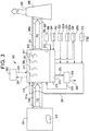
- FIGURE 3 Schematically illustrated in Figure 3 , is an embodiment of the subject system and method of present invention.
- the system illustrated in FIGURE 3 has features in common with those illustrated in FIGURE 1 .
- features illustrated in FIGURE 3 common to those of FIGURE 1 are signified using the same numbers but with the number "3" preceding them.
- waste 312 is combusted in boiler 314.
- Flue gas FG produced in the boiler 314 from the combustion of waste 312 flows from opening 336 of boiler 314 at a temperature of approximately 125 °C to 175 °C with approximately 1000 to 1500 mg/Nm 3 HCl, approximately 300 to 500 mg/Nm 3 SO 2 , approximately 10 to 25 mg/Nm 3 NH 3 and approximately 1000 to 3000 mg/Nm 3 fly ash.
- the quantity of flue gas FG flowing from boiler 314 depends on boiler 314 size.
- the boiler 314 is typically sized to where approximately 50000 to 300000 Nm 3 /hour of flue gas FG is produced.
- the subject treatment system 310 has essentially one flue gas cleaning stage. This one cleaning stage of the subject treatment system 310 takes place in a combination wet desulfurization system and condenser 311.
- the combination wet desulfurization system and condenser 311 is fluidly connected to boiler 314 via duct 311a for flue gas flow from the boiler 314 into the combination wet desulfurization system and condenser 311 via opening 319.
- the combination wet desulphurization system and condenser 311 is supplied solvent 322a, typically water, from a fluidly connected solvent source 322, an absorption material 324a, typically lime, from a fluidly connected material source 324 and optionally a recycled absorption material 326a from a fluidly connected recycle source 326.
- slurry 315 is sprayed from nozzles 317 for contract with flue gas FG flowing therethrough thereby cleaning flue gas FG flowing therethrough.
- flue gas FG flows from boiler 314 into fluidly connected combination wet desulphurization system and condenser 311 through opening 319 and exits through opening 321.
- Combination wet desulphurization system and condenser 311 is generally a chamber of any commercially useful configuration.
- Combination wet desulphurization system and condenser 311 an absorption material 324a, such as lime from an absorption material source 324 and optionally a recycled absorption material 326a from recycle source 326, such as recycled lime from collection tank 313, are combined with a solvent 322a, such as water, from a solvent source 322 to form a slurry 315.
- a solvent 322a such as water
- slurry 315 is sprayed from nozzles 317 within combination wet desulphurization system and condenser 311.
- the subject combination wet desulphurization system and condenser 311 may include any of a variety of known condenser types, such as for example a direct contact condenser, e.g., a packed tower or a spray scrubber 365, or an indirect condenser, e.g., tube and shell heat exchangers. Regardless of which type condenser 365 is used in combination wet desulphurization system and condenser 311, a recirculation spray 367 through nozzles 317 is always included in condenser 365 to keep combination wet desulphurization system and condenser 311 surfaces 323 wet and to further clean the flue gas FG flowing therethrough.
- condenser types such as for example a direct contact condenser, e.g., a packed tower or a spray scrubber 365, or an indirect condenser, e.g., tube and shell heat exchangers.
- a recirculation spray 367 through nozzles 317
- the flue gas FG cleaning taking place in combination wet desulphurization system and condenser 311 is used to remove remaining SO 2 from the flue gas FG.
- NaOH 372a is added from a NaOH supply source 372 to maintain a pH of approximately 5.0 to 7.5, or approximately 6.0 to 6.5, in the combination wet desulphurization system and condenser 311. Cooling of the flue gas FG that occurs in combination wet desulphurization system and condenser 311 results in a significant flow of excess water or condensate 374 produced from the humidity of the entering flue gas FG.
- Combination wet desulphurization system and condenser 311 produces approximately 5 to 15 m 3 /hour of condensate 374. Condensate 374 so produced contains Na 2 SO 4 as the primary impurity.
- Condensate 374 is optionally cleaned in a membrane reverse osmosis system 376 or similar purification system.
- system 376 heavy metals, sulphurous compounds, chloride compounds and the like are removed in a concentrate water flow 378.
- concentrate water flow 378 Approximately 20 to 30 percent of condensate 374 forms concentrate water flow 378, which carries approximately > 95 percent of the impurities entering system 376.
- the resultant concentrated water flow 378 is circulated to collection tank 313 of combination wet desulphurization system and condenser 311 for use as make-up water. Clean water 380 is also produced by system 376, which is useful for other purposes.
- the problem encountered may be an increase of SO 2 /sulphite concentrations in the combination wet desulphurization system and condenser 311.
- a relatively small amount such as approximately 0.0001 to 0.200 mM, or approximately 0.020 mM of an oxidation catalyst 382, such as FeSO 4 or the like is added to combination wet desulphurization system and condenser 311.
- air and/or oxygen 386 from an oxygen supply source 388 may be injected into and/or optionally mechanically stirred (not shown) into collection tank 313 of combination wet desulphurization system and condenser 311 for forced oxidation therein.
- flue gas FG flowing outwardly from opening 321 of combination wet desulphurization system and condenser 311 meets and/or exceeds emissions standards and considered "clean" for release to the atmosphere by release through a stack 396.
- flue gas FG flows out of opening 321 of combination wet desulphurization system and condenser 311 and into fluidly connected duct 396a and fluidly connected opening 398 of stack 396 for release therefrom into the atmosphere via opening 399.
- heat 300 recovered from the cooling of the flue gas FG in combination wet desulphurization system and condenser 311 may be used in a district heating system 302.
- heat 300 from combination wet desulphurization system and condenser 311 is used in the district heating system 302 and then returned to combination wet desulphurization system and condenser 311 as coolant 304 for cooling the flue gas FG in combination wet desulphurization system and condenser 311.
- Methods of using the system embodiments illustrated in Figures 1-3 and described above are useful for removing SO 2 from flue gas produced by waste combustion.
- One such method of using the subject system (not in accordance with the invention) entails flowing waste combustion flue gas through three cleaning stages to remove SO 2 from the flue gas comprising SO 2 to produce cleaned flue gas for release of the cleaned flue gas to the atmosphere via a stack.
- waste combustion flue gas is passed through a semi-dry flue gas desulfurization system, a quench and a condenser to produce cleaned flue gas.
- the waste combustion flue gas is contacted with a solvent moistened absorption material and/or recycled absorption material to form dry particulates in accordance with Reactions 5 and 6 above.
- the waste combustion flue gas then flows through a quench where it is sprayed with recirculated water to fully humidify the waste combustion flue gas under relatively low pH conditions in the range of approximately 0 to 4, or a pH of approximately 1.
- the waste combustion flue gas flows through a condenser where it is sprayed with a water recirculation spray, NaOH from an NaOH supply source to maintain a pH of approximately 5.0 to 7.5, or approximately 6.0 to 6.5, in the condenser, and a relatively small amount of an oxidation catalyst, such as FeSO 4 .
- a water recirculation spray NaOH from an NaOH supply source to maintain a pH of approximately 5.0 to 7.5, or approximately 6.0 to 6.5, in the condenser
- an oxidation catalyst such as FeSO 4
- An additional benefit to the method so described is the optional use of heat energy from the system condenser in a district heating system and/or optional cleaning of condensation water from the condenser by a reverse osmosis system for uses of the so produced water outside the subject system.
- Another method of using the subject system entails flowing waste combustion flue gas through two cleaning stages to remove SO 2 from the flue gas comprising SO 2 to produce cleaned flue gas for release of the cleaned flue gas to the atmosphere via a stack.
- waste combustion flue gas is passed through a combination wet desulfurization system and quench and a combination wet desulfurization system and condenser to produce cleaned flue gas.
- the waste combustion flue gas is contacted with a solvent and absorption material slurry, which may or may not include recycled absorption material.
- the waste combustion flue gas flows through combination wet desulfurization system and quench it is sprayed with the slurry and recirculated water to fully humidify the waste combustion flue gas under relatively low pH conditions in the range of approximately 0 to 4, or a pH of approximately 1.
- the waste combustion flue gas flows through a wet desulfurization system and condenser where it is sprayed with a water recirculation spray, NaOH from an NaOH supply source to maintain a pH of approximately 5.0 to 7.5, or approximately 6.0 to 6.5, in the condenser, and a relatively small amount of an oxidation catalyst, such as FeSO 4 .
- waste combustion flue gas is cleaned to produce cleaned flue gas for release to the atmosphere via an associated stack.
- An additional benefit to the method so described is the optional use of heat energy from the combination wet desulfurization system and condenser in a district heating system and/or optional cleaning of condensation water from the combined wet desulfurization system and condenser by a reverse osmosis system for uses of the so produced water outside the subject system.
- a method of using the subject system entails flowing waste combustion flue gas through one cleaning stage to remove SO 2 from the flue gas comprising SO 2 to produce cleaned flue gas for release of the cleaned flue gas to the atmosphere via a stack.
- waste combustion flue gas is passed through a combination wet desulfurization system and condenser to produce cleaned flue gas.
- the waste combustion flue gas is contacted with a solvent and absorption material slurry, which may or may not include recycled absorption material.
- a solvent and absorption material slurry which may or may not include recycled absorption material.
- waste combustion flue gas flowing through the wet desulfurization system and condenser also is sprayed with NaOH from an NaOH supply source to maintain a pH of approximately 5.0 to 7.5, or approximately 6.0 to 6.5 in the condenser, and a relatively small amount of an oxidation catalyst, such as FeSO 4 .
- an oxidation catalyst such as FeSO 4 .
- An additional benefit to the method so described is the optional use of heat energy from the combination wet desulfurization system and condenser in a district heating system and/or optional cleaning of condensation water from the combined wet desulfurization system and condenser by a reverse osmosis system for uses of the so produced water outside the subject system.
Landscapes
- Engineering & Computer Science (AREA)
- Chemical & Material Sciences (AREA)
- Environmental & Geological Engineering (AREA)
- Chemical Kinetics & Catalysis (AREA)
- General Chemical & Material Sciences (AREA)
- Analytical Chemistry (AREA)
- Health & Medical Sciences (AREA)
- Oil, Petroleum & Natural Gas (AREA)
- Biomedical Technology (AREA)
- Combustion & Propulsion (AREA)
- Mechanical Engineering (AREA)
- General Engineering & Computer Science (AREA)
- Treating Waste Gases (AREA)
Claims (8)
- System (310) zum Entfernen von SO2 aus SO2-haltigem Abfallverbrennungsrauchgas (FG), umfassend eine Kombination aus Nassentschwefelungssystem und Kondensator (311) zum Inkontaktbringen des Rauchgases mit einem rezirkulierten Wassersprühnebel, NaOH (372a) und einem Oxidationskatalysator (382), um gereinigtes Rauchgas zur Freisetzung in die Atmosphäre zu erzeugen, dadurch gekennzeichnet, dass das System (310) im Wesentlichen eine Rauchgasreinigungsstufe aufweist, wobei die Kombination aus Nassentschwefelungssystem und Kondensator (311) im Allgemeinen eine Kammer ist, die eine Öffnung (319) zur Fluidverbindung mit einem Kessel (314), um zu ermöglichen, dass Rauchgas (FG) aus dem Kessel (314) in die Kammer strömt, und eine weitere Öffnung (321) umfasst, die ermöglicht, dass das Rauchgas (FG) aus der Kammer austritt,
das System (310) eine Lösungsmittelquelle (322) und eine Absorptionsmaterialquelle (324) umfasst, die beide mit der Kammer in Fluidverbindung stehen,
die Kammer einen Sammelbehälter (313) umfasst, in dem Lösungsmittel (322a), Absorptionsmaterial (324a, 326a) kombiniert werden, um eine Aufschlämmung (315) zu bilden,
Düsen (317) innerhalb der Kammer zum Besprühen des Rauchgases (FG) mit der Aufschlämmung (315) mittels eines Rezirkulationssprühnebels (367), um das Rauchgas (FG) vollständig zu befeuchten und alle Oberflächen (323) innerhalb der Kammer vollständig zu benetzen,
eine NaOH-Versorgungsquelle (372) zum Hinzufügen von NaOH (372a) zum Aufrechterhalten eines pH-Werts von etwa 5,0 bis 7,5 in der Kammer und
eine Katalysatorversorgungsquelle (384) zum Zuführen eines Oxidationskatalysators (382) zu der Kombination aus Nassentschwefelungssystem und Kondensator (311), um die Oxidation von Sulfit zu Sulfat zu fördern. - System (310) nach Anspruch 1, ferner umfassend:
eine Sauerstoffversorgungsquelle (388), um dem System (310) Luft, Sauerstoff oder ein mit Sauerstoff angereichertes Gas bereitzustellen, um die Oxidation von Sulfit zu Sulfat darin zu fördern. - System (310) nach einem der Ansprüche 1 oder 2, wobei ein Femwärmesystem (302) bereitgestellt ist, um Wärme von der Kombination aus Nassentschwefelungssystem und Kondensator (263, 311) zu verwenden.
- Verfahren zum Entfernen von SO2 aus SO2-haltigem Abfallverbrennungsrauchgas unter Verwendung des Systems (310) nach einem der vorstehenden Ansprüche, wobei das Verfahren umfasst:
Strömenlassen des Rauchgases durch die Kombination aus Nassentschwefelungssystem und Kondensator (311), um gereinigtes Rauchgas zur Freisetzung in die Atmosphäre zu erzeugen, wobei das Abfallverbrennungsrauchgas (FG) mit dem Lösungsmittel und der Absorptionsmaterialaufschlämmung und rezirkuliertem Wasser besprüht wird, während es durch die Kombination aus Nassentschwefelungssystem und Kondensator (311) strömt, und Besprühen des Rauchgases mit NaOH, um einen pH-Wert von ca. 5,0 bis 7,5 im Kondensator aufrechtzuerhalten, und einen Oxidationskatalysator, um die Oxidation von Sulfit zu Sulfat zu fördern. - Verfahren nach Anspruch 4, ferner umfassend:
Bereitstellen von Luft, Sauerstoff oder einem mit Sauerstoff angereicherten Gas für die Kombination aus Nassentschwefelungssystem und Kondensator (263, 311), um die Oxidation von Sulfit zu Sulfat darin zu fördern. - Verfahren nach einem der Ansprüche 4 bis 5, wobei der Oxidationskatalysator (382) FeSO4 ist.
- Verfahren nach einem der Ansprüche 4 bis 6, wobei der Oxidationskatalysator (382) 0,0001 bis 0,200 mM FeSO4 ist.
- Verfahren nach einem der Ansprüche 4 bis 7, wobei Wärme aus der Kombination aus Nassentschwefelungssystem und Kondensator (263, 311) in einem Fernwärmesystem (102, 202, 302) verwendet wird.
Applications Claiming Priority (2)
| Application Number | Priority Date | Filing Date | Title |
|---|---|---|---|
| US201361769982P | 2013-02-27 | 2013-02-27 | |
| US13/848,947 US8877152B2 (en) | 2013-02-27 | 2013-03-22 | Oxidation system and method for cleaning waste combustion flue gas |
Publications (2)
| Publication Number | Publication Date |
|---|---|
| EP2772300A1 EP2772300A1 (de) | 2014-09-03 |
| EP2772300B1 true EP2772300B1 (de) | 2021-02-24 |
Family
ID=50184764
Family Applications (1)
| Application Number | Title | Priority Date | Filing Date |
|---|---|---|---|
| EP14156586.1A Not-in-force EP2772300B1 (de) | 2013-02-27 | 2014-02-25 | Oxidationssystem und Verfahren zur Reinigung von Abfallverbrennungsabgasen |
Country Status (2)
| Country | Link |
|---|---|
| US (1) | US8877152B2 (de) |
| EP (1) | EP2772300B1 (de) |
Families Citing this family (16)
| Publication number | Priority date | Publication date | Assignee | Title |
|---|---|---|---|---|
| US9327237B2 (en) * | 2014-07-23 | 2016-05-03 | Alcoa Inc. | Systems and methods for removing sulfur dioxide from a gas stream |
| CN104689696A (zh) * | 2015-02-03 | 2015-06-10 | 北京理工大学 | 烟气回收再利用环保节能系统 |
| CN104592542B (zh) * | 2015-02-05 | 2017-10-27 | 齐鲁工业大学 | 一种废纸纤维清洁生产发泡缓冲材料的方法 |
| CN105944544A (zh) * | 2016-07-13 | 2016-09-21 | 北京华福工程有限公司 | 石油化工酸性尾气处理系统 |
| CN106178940B (zh) * | 2016-07-29 | 2019-08-16 | 中冶宝钢技术服务有限公司 | 用于湿法脱硫的钢渣基改性脱硫剂及其制备方法和应用 |
| DK3323496T3 (da) * | 2016-11-18 | 2020-12-14 | General Electric Technology Gmbh | Apparat og fremgangsmåde til reduktion af emissioner af sur gas med nul-væskeudledning af spildevand |
| CN107213732A (zh) * | 2017-05-26 | 2017-09-29 | 北京哈宜节能环保科技开发股份有限公司 | 湿法脱硫烟气中水蒸气、tds和so3脱除方法及装置 |
| CN109647173A (zh) * | 2018-12-28 | 2019-04-19 | 浙江天蓝环保技术股份有限公司 | 一种半干法-湿法串联的so2烟气脱硫工艺及装置 |
| CN110090542A (zh) * | 2019-05-24 | 2019-08-06 | 李西平 | 一种有机废气的处理系统及其处理方法 |
| EP3798516B1 (de) * | 2019-09-30 | 2023-06-07 | Caligo Industria Oy | Anordnung und verfahren zur wärmeübertragung |
| CN111359408B (zh) * | 2020-04-30 | 2024-03-26 | 西安交通大学 | 一种协同热发电的脱硫脱硝烟气综合治理装置及方法 |
| CN111603930A (zh) * | 2020-06-02 | 2020-09-01 | 黄伟 | 一种清洁型煤燃烧锅炉 |
| CN111957170A (zh) * | 2020-08-13 | 2020-11-20 | 四川淼垚森环保科技有限公司 | 一种燃烧烟气再利用装置及其使用方法 |
| CN112206641A (zh) * | 2020-09-23 | 2021-01-12 | 武汉龙净环保工程有限公司 | 一种单塔多级循环氨/硫铵法烟气脱硫方法 |
| FI131955B1 (en) * | 2023-12-29 | 2026-03-11 | Aliceco Ip Oy | Plant and process for efficient district heating production and flue gas purification |
| CN121130640A (zh) * | 2025-09-26 | 2025-12-16 | 浙江大学 | 垃圾焚烧飞灰水洗液协同烟气净化的处理系统与方法 |
Family Cites Families (21)
| Publication number | Priority date | Publication date | Assignee | Title |
|---|---|---|---|---|
| US2418167A (en) * | 1940-10-05 | 1947-04-01 | Paper Patents Co | Recovery of so2 from digester blowoff gases |
| DE2304496C3 (de) | 1973-01-31 | 1978-08-17 | Metallgesellschaft Ag, 6000 Frankfurt | Verfahren zum Entfernen von SO2 aus Abgasen |
| IT1117664B (it) | 1977-01-14 | 1986-02-17 | Italsider Spa | Metodo per l abbattimento della anidride solforosa |
| DE2708919C2 (de) | 1977-03-02 | 1982-05-27 | Dr. C. Otto & Comp. Gmbh, 4630 Bochum | Verfahren zur Reinigung von SO↓2↓-haltigen Industrieabgasen |
| US4284608A (en) * | 1977-07-18 | 1981-08-18 | American Electronic Laboratories, Inc. | Process for regenerating sulfur dioxide gas scrubbing solutions |
| JPS5472771A (en) * | 1977-11-22 | 1979-06-11 | Toray Ind Inc | Removing method of sulfur oxides |
| US4248842A (en) | 1979-03-05 | 1981-02-03 | International Telephone & Telegraph Corporation | Removal of contaminants and recovery of by-products from hot waste gas stream |
| SE437123B (sv) * | 1982-08-23 | 1985-02-11 | Svenska Rotor Maskiner Ab | Sett att rena rokgas fran en forbrenningsprocess |
| US4990315A (en) | 1988-02-10 | 1991-02-05 | Tampa Electric Company | Apparatus for desulfurization |
| US5100634A (en) | 1990-09-27 | 1992-03-31 | Long Joseph F | Method for sulfur dioxide and nitrogen reduction in boiler stacks |
| US6217839B1 (en) * | 1999-08-20 | 2001-04-17 | Uop Llc | Removal of sulfur compounds from gaseous waste streams |
| JP4841065B2 (ja) | 2001-06-21 | 2011-12-21 | 三菱重工メカトロシステムズ株式会社 | 排煙のso3分除去装置 |
| EP1578517B1 (de) * | 2002-12-21 | 2008-03-12 | Haldor Topsoe A/S | Verfahren zum entfernen von so2 aus abgasen durch reaktion mith2o2 |
| DE102004022506B4 (de) * | 2004-05-05 | 2012-06-21 | Outokumpu Oyj | Verfahren und Anlage zur Herstellung von Schwefelsäure aus schwefeldioxidreichen Gasen |
| DE102005041794A1 (de) * | 2005-09-02 | 2007-03-08 | Basf Ag | Verfahren und Vorrichtung zum Entfernen von Schwefeldioxid aus einem trockenen Gasstrom |
| US20070154373A1 (en) | 2006-01-05 | 2007-07-05 | Envirosolv Energy Llc | Methods for regenerating oxidants used for removing pollutants from a gas stream |
| US8226754B2 (en) | 2008-10-15 | 2012-07-24 | Urs Corporation | Low cost wet lime/limestone/sodium FGD system |
| DE102010061538A1 (de) | 2010-01-27 | 2011-07-28 | Hitachi Power Europe GmbH, 47059 | Rauchgaswäscher mit zugeordnetem Kühlturm |
| LU91685B1 (de) * | 2010-05-07 | 2011-11-08 | Cppe Carbon Process & Plant Engineering S A | Verfahren zur katalytischen Entfernung von Kohlendioxyd und Schwefeldioxid aus Abgasen |
| WO2011147431A1 (en) * | 2010-05-27 | 2011-12-01 | Haldor Topsoe A/S | Process and apparatus for sulphuric acid production |
| US8535630B2 (en) * | 2011-11-07 | 2013-09-17 | Bechtel Power Corporation | Method and apparatus for SOx and CO2 removal from flue gas |
-
2013
- 2013-03-22 US US13/848,947 patent/US8877152B2/en not_active Expired - Fee Related
-
2014
- 2014-02-25 EP EP14156586.1A patent/EP2772300B1/de not_active Not-in-force
Non-Patent Citations (1)
| Title |
|---|
| None * |
Also Published As
| Publication number | Publication date |
|---|---|
| US8877152B2 (en) | 2014-11-04 |
| US20140241971A1 (en) | 2014-08-28 |
| EP2772300A1 (de) | 2014-09-03 |
Similar Documents
| Publication | Publication Date | Title |
|---|---|---|
| EP2772300B1 (de) | Oxidationssystem und Verfahren zur Reinigung von Abfallverbrennungsabgasen | |
| EP2335804B1 (de) | Verfahren und Vorrichtung zum Reinigen eines kohlenstoffdioxidreichen Abgases | |
| US6143263A (en) | Method and system for SO2 and SO3 control by dry sorbent/reagent injection and wet scrubbing | |
| US9155993B2 (en) | Exhaust-gas treatment apparatus and exhaust-gas treatment method | |
| CN101352646B (zh) | 一种利用紫外光双重作用的烟气脱硝方法 | |
| US7998446B2 (en) | Flue gas desulfurization process utilizing hydrogen peroxide | |
| CN103619445B (zh) | 具有氨回收的基于冷冻氨的二氧化碳捕集系统及使用方法 | |
| US9650269B2 (en) | System and method for reducing gas emissions from wet flue gas desulfurization waste water | |
| JP2015144986A (ja) | 排ガス処理装置 | |
| CZ291726B6 (cs) | Způsob zpracovávání spalin | |
| CN101254392A (zh) | 节能型亚硫酸钠循环脱硫装置及方法 | |
| CN110314505B (zh) | 一种碱行业干铵工段含氨尾气处理装置及其处理方法 | |
| WO2014103682A1 (ja) | 排ガス処理設備およびこれを用いるガスタービン発電システム | |
| JP2001170444A (ja) | 湿式排煙脱硫装置 | |
| CN109126435A (zh) | 一种双碱法烟气脱硫工艺 | |
| PL190432B1 (pl) | Sposób obróbki gazu spalinowego | |
| CN211274164U (zh) | 一种碱行业干铵工段含氨尾气处理装置 | |
| JP2000053980A (ja) | ガス精製方法 | |
| CN207581563U (zh) | 一种新型氨水循环脱硫系统 | |
| JP3358904B2 (ja) | 排ガスの処理方法 | |
| CN114504932A (zh) | 一种烟气联合处理及废水零排放的装置及方法 | |
| CN222709374U (zh) | 烟气脱硫系统 | |
| CN113082976A (zh) | 一种烟气先脱硝后脱硫工艺中的碱性湿法脱硫工艺及副产物处理方法 | |
| EP4614065A1 (de) | Rauchgasbehandlung | |
| CN110124496A (zh) | 一种双循环脱硫工艺方法 |
Legal Events
| Date | Code | Title | Description |
|---|---|---|---|
| PUAI | Public reference made under article 153(3) epc to a published international application that has entered the european phase |
Free format text: ORIGINAL CODE: 0009012 |
|
| 17P | Request for examination filed |
Effective date: 20140225 |
|
| AK | Designated contracting states |
Kind code of ref document: A1 Designated state(s): AL AT BE BG CH CY CZ DE DK EE ES FI FR GB GR HR HU IE IS IT LI LT LU LV MC MK MT NL NO PL PT RO RS SE SI SK SM TR |
|
| AX | Request for extension of the european patent |
Extension state: BA ME |
|
| RAP1 | Party data changed (applicant data changed or rights of an application transferred) |
Owner name: GENERAL ELECTRIC TECHNOLOGY GMBH |
|
| STAA | Information on the status of an ep patent application or granted ep patent |
Free format text: STATUS: EXAMINATION IS IN PROGRESS |
|
| 17Q | First examination report despatched |
Effective date: 20190424 |
|
| GRAP | Despatch of communication of intention to grant a patent |
Free format text: ORIGINAL CODE: EPIDOSNIGR1 |
|
| STAA | Information on the status of an ep patent application or granted ep patent |
Free format text: STATUS: GRANT OF PATENT IS INTENDED |
|
| INTG | Intention to grant announced |
Effective date: 20200930 |
|
| GRAS | Grant fee paid |
Free format text: ORIGINAL CODE: EPIDOSNIGR3 |
|
| GRAA | (expected) grant |
Free format text: ORIGINAL CODE: 0009210 |
|
| STAA | Information on the status of an ep patent application or granted ep patent |
Free format text: STATUS: THE PATENT HAS BEEN GRANTED |
|
| AK | Designated contracting states |
Kind code of ref document: B1 Designated state(s): AL AT BE BG CH CY CZ DE DK EE ES FI FR GB GR HR HU IE IS IT LI LT LU LV MC MK MT NL NO PL PT RO RS SE SI SK SM TR |
|
| REG | Reference to a national code |
Ref country code: GB Ref legal event code: FG4D |
|
| REG | Reference to a national code |
Ref country code: CH Ref legal event code: EP |
|
| REG | Reference to a national code |
Ref country code: DE Ref legal event code: R096 Ref document number: 602014075060 Country of ref document: DE |
|
| REG | Reference to a national code |
Ref country code: AT Ref legal event code: REF Ref document number: 1363746 Country of ref document: AT Kind code of ref document: T Effective date: 20210315 |
|
| REG | Reference to a national code |
Ref country code: IE Ref legal event code: FG4D |
|
| RAP4 | Party data changed (patent owner data changed or rights of a patent transferred) |
Owner name: GENERAL ELECTRIC TECHNOLOGY GMBH |
|
| PGFP | Annual fee paid to national office [announced via postgrant information from national office to epo] |
Ref country code: DE Payment date: 20210217 Year of fee payment: 8 |
|
| REG | Reference to a national code |
Ref country code: NO Ref legal event code: T2 Effective date: 20210224 |
|
| REG | Reference to a national code |
Ref country code: LT Ref legal event code: MG9D |
|
| REG | Reference to a national code |
Ref country code: NL Ref legal event code: MP Effective date: 20210224 |
|
| PG25 | Lapsed in a contracting state [announced via postgrant information from national office to epo] |
Ref country code: BG Free format text: LAPSE BECAUSE OF FAILURE TO SUBMIT A TRANSLATION OF THE DESCRIPTION OR TO PAY THE FEE WITHIN THE PRESCRIBED TIME-LIMIT Effective date: 20210524 Ref country code: GR Free format text: LAPSE BECAUSE OF FAILURE TO SUBMIT A TRANSLATION OF THE DESCRIPTION OR TO PAY THE FEE WITHIN THE PRESCRIBED TIME-LIMIT Effective date: 20210525 Ref country code: HR Free format text: LAPSE BECAUSE OF FAILURE TO SUBMIT A TRANSLATION OF THE DESCRIPTION OR TO PAY THE FEE WITHIN THE PRESCRIBED TIME-LIMIT Effective date: 20210224 Ref country code: FI Free format text: LAPSE BECAUSE OF FAILURE TO SUBMIT A TRANSLATION OF THE DESCRIPTION OR TO PAY THE FEE WITHIN THE PRESCRIBED TIME-LIMIT Effective date: 20210224 Ref country code: PT Free format text: LAPSE BECAUSE OF FAILURE TO SUBMIT A TRANSLATION OF THE DESCRIPTION OR TO PAY THE FEE WITHIN THE PRESCRIBED TIME-LIMIT Effective date: 20210624 Ref country code: LT Free format text: LAPSE BECAUSE OF FAILURE TO SUBMIT A TRANSLATION OF THE DESCRIPTION OR TO PAY THE FEE WITHIN THE PRESCRIBED TIME-LIMIT Effective date: 20210224 |
|
| PGFP | Annual fee paid to national office [announced via postgrant information from national office to epo] |
Ref country code: NO Payment date: 20210325 Year of fee payment: 8 |
|
| REG | Reference to a national code |
Ref country code: AT Ref legal event code: MK05 Ref document number: 1363746 Country of ref document: AT Kind code of ref document: T Effective date: 20210224 |
|
| PG25 | Lapsed in a contracting state [announced via postgrant information from national office to epo] |
Ref country code: SE Free format text: LAPSE BECAUSE OF FAILURE TO SUBMIT A TRANSLATION OF THE DESCRIPTION OR TO PAY THE FEE WITHIN THE PRESCRIBED TIME-LIMIT Effective date: 20210224 Ref country code: NL Free format text: LAPSE BECAUSE OF FAILURE TO SUBMIT A TRANSLATION OF THE DESCRIPTION OR TO PAY THE FEE WITHIN THE PRESCRIBED TIME-LIMIT Effective date: 20210224 Ref country code: LV Free format text: LAPSE BECAUSE OF FAILURE TO SUBMIT A TRANSLATION OF THE DESCRIPTION OR TO PAY THE FEE WITHIN THE PRESCRIBED TIME-LIMIT Effective date: 20210224 Ref country code: PL Free format text: LAPSE BECAUSE OF FAILURE TO SUBMIT A TRANSLATION OF THE DESCRIPTION OR TO PAY THE FEE WITHIN THE PRESCRIBED TIME-LIMIT Effective date: 20210224 Ref country code: RS Free format text: LAPSE BECAUSE OF FAILURE TO SUBMIT A TRANSLATION OF THE DESCRIPTION OR TO PAY THE FEE WITHIN THE PRESCRIBED TIME-LIMIT Effective date: 20210224 |
|
| PG25 | Lapsed in a contracting state [announced via postgrant information from national office to epo] |
Ref country code: IS Free format text: LAPSE BECAUSE OF FAILURE TO SUBMIT A TRANSLATION OF THE DESCRIPTION OR TO PAY THE FEE WITHIN THE PRESCRIBED TIME-LIMIT Effective date: 20210624 |
|
| REG | Reference to a national code |
Ref country code: BE Ref legal event code: MM Effective date: 20210228 |
|
| PG25 | Lapsed in a contracting state [announced via postgrant information from national office to epo] |
Ref country code: CZ Free format text: LAPSE BECAUSE OF FAILURE TO SUBMIT A TRANSLATION OF THE DESCRIPTION OR TO PAY THE FEE WITHIN THE PRESCRIBED TIME-LIMIT Effective date: 20210224 Ref country code: EE Free format text: LAPSE BECAUSE OF FAILURE TO SUBMIT A TRANSLATION OF THE DESCRIPTION OR TO PAY THE FEE WITHIN THE PRESCRIBED TIME-LIMIT Effective date: 20210224 Ref country code: LI Free format text: LAPSE BECAUSE OF NON-PAYMENT OF DUE FEES Effective date: 20210228 Ref country code: LU Free format text: LAPSE BECAUSE OF NON-PAYMENT OF DUE FEES Effective date: 20210225 Ref country code: CH Free format text: LAPSE BECAUSE OF NON-PAYMENT OF DUE FEES Effective date: 20210228 Ref country code: AT Free format text: LAPSE BECAUSE OF FAILURE TO SUBMIT A TRANSLATION OF THE DESCRIPTION OR TO PAY THE FEE WITHIN THE PRESCRIBED TIME-LIMIT Effective date: 20210224 Ref country code: SM Free format text: LAPSE BECAUSE OF FAILURE TO SUBMIT A TRANSLATION OF THE DESCRIPTION OR TO PAY THE FEE WITHIN THE PRESCRIBED TIME-LIMIT Effective date: 20210224 |
|
| REG | Reference to a national code |
Ref country code: DE Ref legal event code: R097 Ref document number: 602014075060 Country of ref document: DE |
|
| PG25 | Lapsed in a contracting state [announced via postgrant information from national office to epo] |
Ref country code: MC Free format text: LAPSE BECAUSE OF FAILURE TO SUBMIT A TRANSLATION OF THE DESCRIPTION OR TO PAY THE FEE WITHIN THE PRESCRIBED TIME-LIMIT Effective date: 20210224 Ref country code: ES Free format text: LAPSE BECAUSE OF FAILURE TO SUBMIT A TRANSLATION OF THE DESCRIPTION OR TO PAY THE FEE WITHIN THE PRESCRIBED TIME-LIMIT Effective date: 20210224 Ref country code: DK Free format text: LAPSE BECAUSE OF FAILURE TO SUBMIT A TRANSLATION OF THE DESCRIPTION OR TO PAY THE FEE WITHIN THE PRESCRIBED TIME-LIMIT Effective date: 20210224 Ref country code: SK Free format text: LAPSE BECAUSE OF FAILURE TO SUBMIT A TRANSLATION OF THE DESCRIPTION OR TO PAY THE FEE WITHIN THE PRESCRIBED TIME-LIMIT Effective date: 20210224 Ref country code: RO Free format text: LAPSE BECAUSE OF FAILURE TO SUBMIT A TRANSLATION OF THE DESCRIPTION OR TO PAY THE FEE WITHIN THE PRESCRIBED TIME-LIMIT Effective date: 20210224 |
|
| PLBE | No opposition filed within time limit |
Free format text: ORIGINAL CODE: 0009261 |
|
| STAA | Information on the status of an ep patent application or granted ep patent |
Free format text: STATUS: NO OPPOSITION FILED WITHIN TIME LIMIT |
|
| GBPC | Gb: european patent ceased through non-payment of renewal fee |
Effective date: 20210524 |
|
| PG25 | Lapsed in a contracting state [announced via postgrant information from national office to epo] |
Ref country code: FR Free format text: LAPSE BECAUSE OF NON-PAYMENT OF DUE FEES Effective date: 20210424 Ref country code: IE Free format text: LAPSE BECAUSE OF NON-PAYMENT OF DUE FEES Effective date: 20210225 Ref country code: AL Free format text: LAPSE BECAUSE OF FAILURE TO SUBMIT A TRANSLATION OF THE DESCRIPTION OR TO PAY THE FEE WITHIN THE PRESCRIBED TIME-LIMIT Effective date: 20210224 |
|
| 26N | No opposition filed |
Effective date: 20211125 |
|
| PG25 | Lapsed in a contracting state [announced via postgrant information from national office to epo] |
Ref country code: SI Free format text: LAPSE BECAUSE OF FAILURE TO SUBMIT A TRANSLATION OF THE DESCRIPTION OR TO PAY THE FEE WITHIN THE PRESCRIBED TIME-LIMIT Effective date: 20210224 |
|
| PG25 | Lapsed in a contracting state [announced via postgrant information from national office to epo] |
Ref country code: IT Free format text: LAPSE BECAUSE OF FAILURE TO SUBMIT A TRANSLATION OF THE DESCRIPTION OR TO PAY THE FEE WITHIN THE PRESCRIBED TIME-LIMIT Effective date: 20210224 Ref country code: GB Free format text: LAPSE BECAUSE OF NON-PAYMENT OF DUE FEES Effective date: 20210524 |
|
| PG25 | Lapsed in a contracting state [announced via postgrant information from national office to epo] |
Ref country code: IS Free format text: LAPSE BECAUSE OF FAILURE TO SUBMIT A TRANSLATION OF THE DESCRIPTION OR TO PAY THE FEE WITHIN THE PRESCRIBED TIME-LIMIT Effective date: 20210624 |
|
| PG25 | Lapsed in a contracting state [announced via postgrant information from national office to epo] |
Ref country code: BE Free format text: LAPSE BECAUSE OF NON-PAYMENT OF DUE FEES Effective date: 20210228 |
|
| REG | Reference to a national code |
Ref country code: DE Ref legal event code: R119 Ref document number: 602014075060 Country of ref document: DE |
|
| REG | Reference to a national code |
Ref country code: NO Ref legal event code: MMEP |
|
| PG25 | Lapsed in a contracting state [announced via postgrant information from national office to epo] |
Ref country code: NO Free format text: LAPSE BECAUSE OF NON-PAYMENT OF DUE FEES Effective date: 20220228 |
|
| PG25 | Lapsed in a contracting state [announced via postgrant information from national office to epo] |
Ref country code: DE Free format text: LAPSE BECAUSE OF NON-PAYMENT OF DUE FEES Effective date: 20220901 |
|
| PG25 | Lapsed in a contracting state [announced via postgrant information from national office to epo] |
Ref country code: HU Free format text: LAPSE BECAUSE OF FAILURE TO SUBMIT A TRANSLATION OF THE DESCRIPTION OR TO PAY THE FEE WITHIN THE PRESCRIBED TIME-LIMIT; INVALID AB INITIO Effective date: 20140225 |
|
| PG25 | Lapsed in a contracting state [announced via postgrant information from national office to epo] |
Ref country code: CY Free format text: LAPSE BECAUSE OF FAILURE TO SUBMIT A TRANSLATION OF THE DESCRIPTION OR TO PAY THE FEE WITHIN THE PRESCRIBED TIME-LIMIT Effective date: 20210224 |
|
| PG25 | Lapsed in a contracting state [announced via postgrant information from national office to epo] |
Ref country code: MK Free format text: LAPSE BECAUSE OF FAILURE TO SUBMIT A TRANSLATION OF THE DESCRIPTION OR TO PAY THE FEE WITHIN THE PRESCRIBED TIME-LIMIT Effective date: 20210224 |
|
| PG25 | Lapsed in a contracting state [announced via postgrant information from national office to epo] |
Ref country code: MT Free format text: LAPSE BECAUSE OF FAILURE TO SUBMIT A TRANSLATION OF THE DESCRIPTION OR TO PAY THE FEE WITHIN THE PRESCRIBED TIME-LIMIT Effective date: 20210224 |
|
| PG25 | Lapsed in a contracting state [announced via postgrant information from national office to epo] |
Ref country code: TR Free format text: LAPSE BECAUSE OF FAILURE TO SUBMIT A TRANSLATION OF THE DESCRIPTION OR TO PAY THE FEE WITHIN THE PRESCRIBED TIME-LIMIT Effective date: 20210224 |