EP2772614A1 - Turbomaschinenschaufelherstellungsverfahren - Google Patents
Turbomaschinenschaufelherstellungsverfahren Download PDFInfo
- Publication number
- EP2772614A1 EP2772614A1 EP14157392.3A EP14157392A EP2772614A1 EP 2772614 A1 EP2772614 A1 EP 2772614A1 EP 14157392 A EP14157392 A EP 14157392A EP 2772614 A1 EP2772614 A1 EP 2772614A1
- Authority
- EP
- European Patent Office
- Prior art keywords
- plate
- blade
- producing
- projecting appendage
- airfoil
- Prior art date
- Legal status (The legal status is an assumption and is not a legal conclusion. Google has not performed a legal analysis and makes no representation as to the accuracy of the status listed.)
- Granted
Links
- 230000008878 coupling Effects 0.000 claims abstract description 51
- 238000010168 coupling process Methods 0.000 claims abstract description 51
- 238000005859 coupling reaction Methods 0.000 claims abstract description 51
- 238000000034 method Methods 0.000 claims abstract description 46
- 229910052751 metal Inorganic materials 0.000 claims description 26
- 239000002184 metal Substances 0.000 claims description 26
- 238000003754 machining Methods 0.000 claims description 19
- 238000009966 trimming Methods 0.000 claims description 14
- 239000000463 material Substances 0.000 claims description 12
- 230000000295 complement effect Effects 0.000 claims description 11
- 238000003466 welding Methods 0.000 claims description 8
- 238000007493 shaping process Methods 0.000 claims description 6
- 238000007789 sealing Methods 0.000 abstract description 3
- 238000003801 milling Methods 0.000 description 9
- 238000004519 manufacturing process Methods 0.000 description 4
- 238000005520 cutting process Methods 0.000 description 3
- 238000005242 forging Methods 0.000 description 3
- 230000002093 peripheral effect Effects 0.000 description 3
- 239000011324 bead Substances 0.000 description 2
- 238000004512 die casting Methods 0.000 description 2
- 229910000838 Al alloy Inorganic materials 0.000 description 1
- 229910000831 Steel Inorganic materials 0.000 description 1
- 229910001069 Ti alloy Inorganic materials 0.000 description 1
- 230000001419 dependent effect Effects 0.000 description 1
- 230000013011 mating Effects 0.000 description 1
- 239000010959 steel Substances 0.000 description 1
Images


Classifications
-
- B—PERFORMING OPERATIONS; TRANSPORTING
- B23—MACHINE TOOLS; METAL-WORKING NOT OTHERWISE PROVIDED FOR
- B23P—METAL-WORKING NOT OTHERWISE PROVIDED FOR; COMBINED OPERATIONS; UNIVERSAL MACHINE TOOLS
- B23P15/00—Making specific metal objects by operations not covered by a single other subclass or a group in this subclass
- B23P15/04—Making specific metal objects by operations not covered by a single other subclass or a group in this subclass turbine or like blades from several pieces
-
- F—MECHANICAL ENGINEERING; LIGHTING; HEATING; WEAPONS; BLASTING
- F01—MACHINES OR ENGINES IN GENERAL; ENGINE PLANTS IN GENERAL; STEAM ENGINES
- F01D—NON-POSITIVE DISPLACEMENT MACHINES OR ENGINES, e.g. STEAM TURBINES
- F01D5/00—Blades; Blade-carrying members; Heating, heat-insulating, cooling or antivibration means on the blades or the members
- F01D5/12—Blades
- F01D5/14—Form or construction
- F01D5/147—Construction, i.e. structural features, e.g. of weight-saving hollow blades
-
- F—MECHANICAL ENGINEERING; LIGHTING; HEATING; WEAPONS; BLASTING
- F01—MACHINES OR ENGINES IN GENERAL; ENGINE PLANTS IN GENERAL; STEAM ENGINES
- F01D—NON-POSITIVE DISPLACEMENT MACHINES OR ENGINES, e.g. STEAM TURBINES
- F01D5/00—Blades; Blade-carrying members; Heating, heat-insulating, cooling or antivibration means on the blades or the members
- F01D5/12—Blades
- F01D5/14—Form or construction
- F01D5/18—Hollow blades, i.e. blades with cooling or heating channels or cavities; Heating, heat-insulating or cooling means on blades
-
- B—PERFORMING OPERATIONS; TRANSPORTING
- B23—MACHINE TOOLS; METAL-WORKING NOT OTHERWISE PROVIDED FOR
- B23C—MILLING
- B23C2215/00—Details of workpieces
- B23C2215/44—Turbine blades
-
- F—MECHANICAL ENGINEERING; LIGHTING; HEATING; WEAPONS; BLASTING
- F05—INDEXING SCHEMES RELATING TO ENGINES OR PUMPS IN VARIOUS SUBCLASSES OF CLASSES F01-F04
- F05D—INDEXING SCHEME FOR ASPECTS RELATING TO NON-POSITIVE-DISPLACEMENT MACHINES OR ENGINES, GAS-TURBINES OR JET-PROPULSION PLANTS
- F05D2230/00—Manufacture
- F05D2230/10—Manufacture by removing material
- F05D2230/14—Micromachining
-
- F—MECHANICAL ENGINEERING; LIGHTING; HEATING; WEAPONS; BLASTING
- F05—INDEXING SCHEMES RELATING TO ENGINES OR PUMPS IN VARIOUS SUBCLASSES OF CLASSES F01-F04
- F05D—INDEXING SCHEME FOR ASPECTS RELATING TO NON-POSITIVE-DISPLACEMENT MACHINES OR ENGINES, GAS-TURBINES OR JET-PROPULSION PLANTS
- F05D2230/00—Manufacture
- F05D2230/10—Manufacture by removing material
- F05D2230/18—Manufacturing tolerances
-
- F—MECHANICAL ENGINEERING; LIGHTING; HEATING; WEAPONS; BLASTING
- F05—INDEXING SCHEMES RELATING TO ENGINES OR PUMPS IN VARIOUS SUBCLASSES OF CLASSES F01-F04
- F05D—INDEXING SCHEME FOR ASPECTS RELATING TO NON-POSITIVE-DISPLACEMENT MACHINES OR ENGINES, GAS-TURBINES OR JET-PROPULSION PLANTS
- F05D2230/00—Manufacture
- F05D2230/20—Manufacture essentially without removing material
- F05D2230/23—Manufacture essentially without removing material by permanently joining parts together
- F05D2230/232—Manufacture essentially without removing material by permanently joining parts together by welding
-
- F—MECHANICAL ENGINEERING; LIGHTING; HEATING; WEAPONS; BLASTING
- F05—INDEXING SCHEMES RELATING TO ENGINES OR PUMPS IN VARIOUS SUBCLASSES OF CLASSES F01-F04
- F05D—INDEXING SCHEME FOR ASPECTS RELATING TO NON-POSITIVE-DISPLACEMENT MACHINES OR ENGINES, GAS-TURBINES OR JET-PROPULSION PLANTS
- F05D2230/00—Manufacture
- F05D2230/50—Building or constructing in particular ways
- F05D2230/51—Building or constructing in particular ways in a modular way, e.g. using several identical or complementary parts or features
-
- Y—GENERAL TAGGING OF NEW TECHNOLOGICAL DEVELOPMENTS; GENERAL TAGGING OF CROSS-SECTIONAL TECHNOLOGIES SPANNING OVER SEVERAL SECTIONS OF THE IPC; TECHNICAL SUBJECTS COVERED BY FORMER USPC CROSS-REFERENCE ART COLLECTIONS [XRACs] AND DIGESTS
- Y02—TECHNOLOGIES OR APPLICATIONS FOR MITIGATION OR ADAPTATION AGAINST CLIMATE CHANGE
- Y02T—CLIMATE CHANGE MITIGATION TECHNOLOGIES RELATED TO TRANSPORTATION
- Y02T50/00—Aeronautics or air transport
- Y02T50/60—Efficient propulsion technologies, e.g. for aircraft
-
- Y—GENERAL TAGGING OF NEW TECHNOLOGICAL DEVELOPMENTS; GENERAL TAGGING OF CROSS-SECTIONAL TECHNOLOGIES SPANNING OVER SEVERAL SECTIONS OF THE IPC; TECHNICAL SUBJECTS COVERED BY FORMER USPC CROSS-REFERENCE ART COLLECTIONS [XRACs] AND DIGESTS
- Y10—TECHNICAL SUBJECTS COVERED BY FORMER USPC
- Y10T—TECHNICAL SUBJECTS COVERED BY FORMER US CLASSIFICATION
- Y10T29/00—Metal working
- Y10T29/49—Method of mechanical manufacture
- Y10T29/49316—Impeller making
- Y10T29/49336—Blade making
- Y10T29/49337—Composite blade
Definitions
- the present invention relates to a turbomachine blade production method.
- the present invention relates to a method of producing a lightweight rotor or stator blade for a compressor or front fan of an aircraft turbine engine, to which use the following description refers purely by way of example.
- rotor and stator blades of aircraft turbine engine compressors substantially comprise a coupling root designed to fit and lock rigidly to the compressor hub or centre blade mounting disk; and an airfoil-shaped oblong member, which cantilevered extends from the coupling root, so as to cantilevered project radially outwards of the blade mounting hub or disk when the coupling root is fixed inside the hub or centre blade mounting disk.
- Stator blades also have an upper coupling head, which is located at the top end of the airfoil-shaped oblong member, i.e. at the opposite end to the coupling root, and is designed to fit and lock rigidly to the outer blade mounting ring of the compressor.
- the lower coupling root, the airfoil-shaped oblong member, and the upper coupling head are usually formed in one piece from a single block of high-strength metal, which is forged and then milled to shape the blade as required.
- Patent Application US2006/039792 describes a method of producing a lightweight aircraft turbine engine blade, which comprises:
- a method of producing a turbomachine blade as defined in Claim 1 and preferably, though not necessarily, in any one of the Claims dependent on Claim 1.
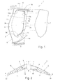
- number 1 indicates as a whole a lightweight turbomachine blade, which may be used to advantage, for example, in the compressor or front fan of a preferably, though not necessarily, aircraft turbine engine.
- Lightweight blade 1 is made of metal, and substantially comprises a lower coupling root 2 designed to fit and lock rigidly to the turbine engine hub or centre blade mounting disk (not shown); an airfoil-shaped oblong member 3 which cantilevered extends from coupling root 2, so as to cantilevered project substantially radially outwards of the hub or blade mounting disk (not shown) when coupling root 2 is fixed inside the hub or centre blade mounting disk, and inside has a large closed weight-reducing cavity 4, the three-dimensional shape of which preferably, though not necessarily, substantially reproduces, to a smaller scale, the three-dimensional shape of airfoil-shaped oblong member 3 as a whole; and an upper coupling head 5, which is located at the second end of airfoil-shaped oblong member 3, i.e. at the opposite end to coupling root 2, and is designed to fit and lock rigidly to the turbine engine outer blade mounting ring (not shown).
- airfoil-shaped oblong member 3 is designed to joint/connect coupling root 2 rigidly to coupling head 5.
- coupling root 2 airfoil-shaped oblong member 3, and coupling head 5 are preferably, though not necessarily, made of titanium alloy, aluminium alloy, or special high-strength steel.
- Airfoil-shaped oblong member 3 in turn, comprises a substantially airfoil-shaped, main plate-like element 6 which connects directly to coupling root 2 and coupling head 5, and which, substantially in the centre of one of its two major faces, has at least one hollow weight-reducing seat 6a of predetermined shape; and a cover plate 7 which closes the opening of hollow seat 6a to form the inner cavity 4 and complete the outer profile of airfoil-shaped oblong member 3.
- hollow weight-reducing seat 6a preferably extends over more than 40% of the total area of the major face of main plate-like element 6 in which hollow seat 6a is formed.
- cover plate 7 instead is complementary in shape to, and serves to airtight seal, the opening of hollow seat 6a.
- cover plate 7 is preferably fixed irremovably to the opening of hollow seat 6a in main plate-like element 6 by a weld bead 8 preferably extending seamlessly along the whole peripheral edge of cover plate 7.
- the shape of hollow seat 6a also roughly reproduces, to a smaller scale, the three-dimensional shape of airfoil-shaped oblong member 3 as a whole.
- main plate-like element 6 in turn is divided into a lower connecting fin 9, which cantilevered projects from coupling root 2 towards coupling head 5 and is formed in one piece with coupling root 2; an upper connecting fin 10, which cantilevered projects from coupling head 5 towards coupling root 2 and is formed in one piece with coupling head 5; and a centre plate-like body 11, which is located between the two connecting fins 9 and 10, is shaped/designed to form an extension of connecting fins 9 and 10, and is butt-welded to, to form one piece with, connecting fins 9 and 10.
- Centre plate-like body 11 is also shaped to at least partly bound/form hollow seat 6a of main plate-like element 6.
- the lower edge 11a of centre plate-like body 11 and the ridge 9a of lower connecting fin 9 are complementary in shape, and are butt welded to each other so that centre plate-like body 11 forms one piece with lower connecting fin 9; and the upper edge 11b of centre plate-like body 11 and the ridge 10b of upper connecting fin 10 are complementary in shape, and are butt welded to each other so that centre plate-like body 11 forms one piece with upper connecting fin 10.
- lower edge 11a of centre plate-like body 11 and ridge 9a of lower connecting fin 9 preferably extend from the leading edge 3a to the trailing edge 3b of airfoil-shaped oblong member 3 along a curved, preferably, though not necessarily, substantially Q (omega) shaped path.
- upper edge 11b of centre plate-like body 11 and ridge 10b of upper connecting fin 10 preferably also extend from the leading edge 3a to the trailing edge 3b of airfoil-shaped oblong member 3 along a curved, preferably, though not necessarily, substantially Q (omega) shaped path.
- the method of producing lightweight blade 1 comprises:
- the method of producing lightweight blade 1 comprises twisting and curving a flat plate 100 by means of a forming process (i.e. plastic deformation of the plate, with no appreciable reduction in its nominal thickness) so that the centreline surface M of the resulting blank plate 101 substantially matches the centreline surface P of the designed centre plate-like body 11.
- a forming process i.e. plastic deformation of the plate, with no appreciable reduction in its nominal thickness
- the 'centreline surface' is the locus/set of points inside the centre plate-like body, which are locally equidistant from the surfaces forming the two major faces of the centre plate-like body.
- the centreline surface M of blank plate 101 is therefore the curved surface formed by the points locally equidistant from the two faces of blank plate 101.
- the centreline surface P of centre plate-like body 11 is the curved surface formed by the points locally equidistant from the surfaces of the two faces of centre plate-like body 11, also taking into account the depression formed by the portion of hollow weight-reducing seat 6a in centre plate-like body 11.
- centreline surface P of centre plate-like body 11 is also determined by the shape of the portion of hollow weight-reducing seat 6a formed in centre plate-like body 11.
- thickness s of flat plate 100 preferably over-approximates the maximum thickness of centre plate-like body 11 of blade 1.
- the difference between the thickness s of flat metal plate 100 and the maximum thickness of centre plate-like body 11 must preferably be less than 2 mm (millimetres).
- the thickness s of flat plate 100 ranges between 5 mm and 40 mm (millimetres).
- flat metal plate 100 of constant thickness over-approximating the maximum thickness of centre plate-like body 11 is preferably obtained by appropriately cutting a large flat metal plate (not shown) of constant thickness greater than the maximum thickness of the centre plate-like body 11 of the airfoil-shaped oblong member 3 of the to-be-made blade 1.
- the method of producing blade 1 comprises cutting, from a large flat metal plate (not shown) of constant thickness over-approximating the maximum thickness of centre plate-like body 11, a plate portion with a contour over-approximating the contour, flat spread-out on the laying plane, of the centre plate-like body 11 of the airfoil-shaped oblong member 3 of the blade 1 to be made, thus to obtain the flat plate 100.
- the thickness of the flat metal plate preferably over-approximates the maximum thickness of centre plate-like body 11 of blade 1, and preferably ranges between 5 mm and 40 mm (millimetres).
- the method of producing blade 1 also comprises
- the method of producing blade 1 then comprises:
- the method of producing blade 1 preferably comprises shaping the lower edge 101a of blank plate 101 and the ridge 103a of projecting appendage 103, so that they extend from the leading edge 3a to the trailing edge 3b of airfoil-shaped oblong member 3 along a curved, preferably, though not necessarily, substantially Q (omega) shaped path.
- the method of producing blade 1 also comprises:
- the method of producing blade 1 then comprises:
- the method of producing blade 1 preferably comprises shaping the upper edge 101b of blank plate 101 and the ridge 105b of projecting appendage 105, so that they extend from the leading edge 3a to the trailing edge 3b of airfoil-shaped oblong member 3 along a curved, preferably, though not necessarily, substantially Q (omega) shaped path.
- the method of producing blade 1 comprises trimming/machining, by milling or other material-removing machining operation, the excess material from the resulting part to obtain coupling root 2, main plate-like element 6 of airfoil-shaped oblong member 3, and coupling head 5 of blade 1 of the desired shape.
- the method of producing blade 1 comprises:
- the method of producing blade 1 comprises closing, preferably sealing, the opening of hollow seat 6a in one of the two faces of main plate-like element 6 by means of a further plate-like element 106 of predetermined thickness, so as to complete the outer profile of airfoil-shaped oblong member 3 and at the same time form the inner cavity 4 in airfoil-shaped oblong member 3.
- the method of producing blade 1 preferably comprises:
- Plate-like element 106 thus forms the cover plate 7 of the airfoil-shaped oblong member.
- the method of producing blade 1 comprises preferably fixing plate-like element 106 irremovably to main plate-like element 6 by means of a weld bead preferably extending seamlessly along the entire peripheral edge of plate-like element 106; and then trimming/machining, by milling or other material-removing machining operation, excess metal off the weld between plate-like element 106 and main plate-like element 6.
- the method of producing lightweight blade 1 preferably provides to obtain plate-like element 106 by cutting, from a large flat, preferably 1-4 mm (millimetre) thick metal sheet (not shown), a plate portion complementary in shape to the contour of the opening of hollow seat 6a.
- the method of producing blade 1 as described has numerous advantages.
- centre plate-like body 11 of main plate-like element 6 by sheet metal forming the flat plate 100, i.e. by press-forming flat plate 100 with no appreciable reduction in the nominal thickness of the plate, greatly reduces the manufacturing cost of blade 1. Which cost saving is considerable in the case of large-size blades 1.
- Sheet metal forming of a flat plate in fact, is a processing technique which is different from forging, which produces a plastic deformation of the plate with no appreciable reduction in its nominal thickness, and which requires much less energy, with all the economic advantages this entails.
- the method of producing blade 1 allows the semifinished parts 102 and 104, eventually forming coupling root 2 and coupling head 5 of blade 1, to be produced separately using production processes best suited to the three-dimensional shape and desired mechanical characteristics of each part.
- blade 1 may have no coupling head 5.
- main plate-like element 6 of airfoil-shaped oblong member 3 is made up of the lower connecting fin 9 which cantilevered projects from, and is formed in one piece with, the coupling root 2; and of centre plate-like body 11 which only forms an extension of lower connecting fin 9, and is butt-welded to, to form one piece with, lower connecting fin 9.
Landscapes
- Engineering & Computer Science (AREA)
- Mechanical Engineering (AREA)
- General Engineering & Computer Science (AREA)
- Architecture (AREA)
- Structures Of Non-Positive Displacement Pumps (AREA)
- Pallets (AREA)
Applications Claiming Priority (1)
| Application Number | Priority Date | Filing Date | Title |
|---|---|---|---|
| IT000030A ITTV20130030A1 (it) | 2013-02-28 | 2013-02-28 | Metodo di costruzione di una paletta per turbomacchine |
Publications (2)
| Publication Number | Publication Date |
|---|---|
| EP2772614A1 true EP2772614A1 (de) | 2014-09-03 |
| EP2772614B1 EP2772614B1 (de) | 2018-04-25 |
Family
ID=48184400
Family Applications (1)
| Application Number | Title | Priority Date | Filing Date |
|---|---|---|---|
| EP14157392.3A Not-in-force EP2772614B1 (de) | 2013-02-28 | 2014-02-28 | Turbomaschinenschaufelherstellungsverfahren |
Country Status (3)
| Country | Link |
|---|---|
| US (1) | US20140237821A1 (de) |
| EP (1) | EP2772614B1 (de) |
| IT (1) | ITTV20130030A1 (de) |
Cited By (2)
| Publication number | Priority date | Publication date | Assignee | Title |
|---|---|---|---|---|
| EP3323979A1 (de) * | 2016-11-17 | 2018-05-23 | United Technologies Corporation | Schaufel mit platte mit umlaufender dichtung |
| FR3063663A1 (fr) * | 2017-03-13 | 2018-09-14 | Mecachrome France | Procede de fabrication de pieces en alliage metallique de forme complexe |
Citations (4)
| Publication number | Priority date | Publication date | Assignee | Title |
|---|---|---|---|---|
| FR2296488A1 (fr) * | 1975-01-02 | 1976-07-30 | Gen Electric | Procede et appareil pour la liaison metallurgique d'elements en superalliage |
| DE19858702A1 (de) * | 1998-12-18 | 2000-06-29 | Mtu Muenchen Gmbh | Schaufel und Rotor für eine Gasturbine und Verfahren zum Verbinden von Schaufelteilen |
| EP1462609A1 (de) * | 2003-03-28 | 2004-09-29 | Snecma Moteurs | Turbomaschinenschaufel mit vermindertem Gewicht und deren Herstellungsweise |
| EP2362066A2 (de) * | 2010-02-26 | 2011-08-31 | United Technologies Corporation | Hohl- Lüfterflügel |
Family Cites Families (2)
| Publication number | Priority date | Publication date | Assignee | Title |
|---|---|---|---|---|
| US20090277009A1 (en) * | 2004-01-09 | 2009-11-12 | Mtu Aero Engines | Method for manufacturing and/or machining components |
| GB0820424D0 (en) * | 2008-11-10 | 2008-12-17 | Rolls Royce Plc | Forming apparatus |
-
2013
- 2013-02-28 IT IT000030A patent/ITTV20130030A1/it unknown
-
2014
- 2014-02-28 EP EP14157392.3A patent/EP2772614B1/de not_active Not-in-force
- 2014-02-28 US US14/194,373 patent/US20140237821A1/en not_active Abandoned
Patent Citations (5)
| Publication number | Priority date | Publication date | Assignee | Title |
|---|---|---|---|---|
| FR2296488A1 (fr) * | 1975-01-02 | 1976-07-30 | Gen Electric | Procede et appareil pour la liaison metallurgique d'elements en superalliage |
| DE19858702A1 (de) * | 1998-12-18 | 2000-06-29 | Mtu Muenchen Gmbh | Schaufel und Rotor für eine Gasturbine und Verfahren zum Verbinden von Schaufelteilen |
| EP1462609A1 (de) * | 2003-03-28 | 2004-09-29 | Snecma Moteurs | Turbomaschinenschaufel mit vermindertem Gewicht und deren Herstellungsweise |
| US20060039792A1 (en) | 2003-03-28 | 2006-02-23 | Snecma Moteurs | Lightened turbomachine blade and its manufacturing process |
| EP2362066A2 (de) * | 2010-02-26 | 2011-08-31 | United Technologies Corporation | Hohl- Lüfterflügel |
Cited By (5)
| Publication number | Priority date | Publication date | Assignee | Title |
|---|---|---|---|---|
| EP3323979A1 (de) * | 2016-11-17 | 2018-05-23 | United Technologies Corporation | Schaufel mit platte mit umlaufender dichtung |
| US10731495B2 (en) | 2016-11-17 | 2020-08-04 | Raytheon Technologies Corporation | Airfoil with panel having perimeter seal |
| FR3063663A1 (fr) * | 2017-03-13 | 2018-09-14 | Mecachrome France | Procede de fabrication de pieces en alliage metallique de forme complexe |
| WO2018167384A1 (fr) | 2017-03-13 | 2018-09-20 | Mecachrome France | Procede de fabrication de pieces en alliage metallique de forme complexe |
| US11891916B2 (en) | 2017-03-13 | 2024-02-06 | Mecachrome France | Method for producing metal alloy parts with complex shape |
Also Published As
| Publication number | Publication date |
|---|---|
| US20140237821A1 (en) | 2014-08-28 |
| EP2772614B1 (de) | 2018-04-25 |
| ITTV20130030A1 (it) | 2014-08-29 |
Similar Documents
| Publication | Publication Date | Title |
|---|---|---|
| CN102834220B (zh) | 制作金属嵌入件以保护复合材料制成的前缘的方法 | |
| CN101985200B (zh) | 用于涡轮机翼的加强边缘的制造方法 | |
| JP3281551B2 (ja) | タービンエンジンの中空羽根の製造方法 | |
| CN104364031B (zh) | 制造用于涡轮引擎的叶片的金属加强件的方法 | |
| EP2727681A1 (de) | Herstellungsverfahren einer leichter gemachten Turbomaschinenschaufel | |
| JP6298808B2 (ja) | 複合物でできた前縁を保護するためのインサートを備えた金属補強材を形成するための方法 | |
| US9120189B2 (en) | Method of making a piece of metal reinforcement | |
| CN106794545B (zh) | 制造前缘护罩的方法 | |
| US8512002B2 (en) | Method of manufacturing an aerofoil | |
| JP2001082388A (ja) | 塑性成形ハイブリッド翼形部 | |
| RU2404039C2 (ru) | Способ изготовления деталей, образующих полую лопатку, посредством прокатки | |
| CN116323089B (zh) | 用于生产进气唇缘的环形扇区的制造 | |
| US9915272B2 (en) | Turbomachine blade and relative production method | |
| US10066492B1 (en) | Turbomachine blade and relative production method | |
| EP2772614B1 (de) | Turbomaschinenschaufelherstellungsverfahren | |
| RU2019128112A (ru) | Способ получения частей из сплавов металлов сложной формы | |
| CA2467846C (en) | Method of manufacturing a hollow blade for a turbine engine | |
| US20160256954A1 (en) | Method and system for diffusion bonded components having internal passages | |
| JP4490881B2 (ja) | Vgsタイプターボチャージャにおける可変翼の製造方法 | |
| RU2463125C2 (ru) | Способ изготовления заготовок широкохордных пустотелых лопаток вентилятора газотурбинного двигателя |
Legal Events
| Date | Code | Title | Description |
|---|---|---|---|
| PUAI | Public reference made under article 153(3) epc to a published international application that has entered the european phase |
Free format text: ORIGINAL CODE: 0009012 |
|
| 17P | Request for examination filed |
Effective date: 20140228 |
|
| AK | Designated contracting states |
Kind code of ref document: A1 Designated state(s): AL AT BE BG CH CY CZ DE DK EE ES FI FR GB GR HR HU IE IS IT LI LT LU LV MC MK MT NL NO PL PT RO RS SE SI SK SM TR |
|
| AX | Request for extension of the european patent |
Extension state: BA ME |
|
| R17P | Request for examination filed (corrected) |
Effective date: 20140820 |
|
| RBV | Designated contracting states (corrected) |
Designated state(s): AL AT BE BG CH CY CZ DE DK EE ES FI FR GB GR HR HU IE IS IT LI LT LU LV MC MK MT NL NO PL PT RO RS SE SI SK SM TR |
|
| GRAP | Despatch of communication of intention to grant a patent |
Free format text: ORIGINAL CODE: EPIDOSNIGR1 |
|
| STAA | Information on the status of an ep patent application or granted ep patent |
Free format text: STATUS: GRANT OF PATENT IS INTENDED |
|
| INTG | Intention to grant announced |
Effective date: 20171114 |
|
| GRAA | (expected) grant |
Free format text: ORIGINAL CODE: 0009210 |
|
| GRAS | Grant fee paid |
Free format text: ORIGINAL CODE: EPIDOSNIGR3 |
|
| STAA | Information on the status of an ep patent application or granted ep patent |
Free format text: STATUS: THE PATENT HAS BEEN GRANTED |
|
| AK | Designated contracting states |
Kind code of ref document: B1 Designated state(s): AL AT BE BG CH CY CZ DE DK EE ES FI FR GB GR HR HU IE IS IT LI LT LU LV MC MK MT NL NO PL PT RO RS SE SI SK SM TR |
|
| REG | Reference to a national code |
Ref country code: GB Ref legal event code: FG4D |
|
| REG | Reference to a national code |
Ref country code: CH Ref legal event code: EP |
|
| REG | Reference to a national code |
Ref country code: AT Ref legal event code: REF Ref document number: 993144 Country of ref document: AT Kind code of ref document: T Effective date: 20180515 |
|
| REG | Reference to a national code |
Ref country code: IE Ref legal event code: FG4D |
|
| REG | Reference to a national code |
Ref country code: DE Ref legal event code: R096 Ref document number: 602014024298 Country of ref document: DE |
|
| REG | Reference to a national code |
Ref country code: NL Ref legal event code: MP Effective date: 20180425 |
|
| REG | Reference to a national code |
Ref country code: LT Ref legal event code: MG4D |
|
| PG25 | Lapsed in a contracting state [announced via postgrant information from national office to epo] |
Ref country code: NL Free format text: LAPSE BECAUSE OF FAILURE TO SUBMIT A TRANSLATION OF THE DESCRIPTION OR TO PAY THE FEE WITHIN THE PRESCRIBED TIME-LIMIT Effective date: 20180425 |
|
| PG25 | Lapsed in a contracting state [announced via postgrant information from national office to epo] |
Ref country code: SE Free format text: LAPSE BECAUSE OF FAILURE TO SUBMIT A TRANSLATION OF THE DESCRIPTION OR TO PAY THE FEE WITHIN THE PRESCRIBED TIME-LIMIT Effective date: 20180425 Ref country code: FI Free format text: LAPSE BECAUSE OF FAILURE TO SUBMIT A TRANSLATION OF THE DESCRIPTION OR TO PAY THE FEE WITHIN THE PRESCRIBED TIME-LIMIT Effective date: 20180425 Ref country code: BG Free format text: LAPSE BECAUSE OF FAILURE TO SUBMIT A TRANSLATION OF THE DESCRIPTION OR TO PAY THE FEE WITHIN THE PRESCRIBED TIME-LIMIT Effective date: 20180725 Ref country code: NO Free format text: LAPSE BECAUSE OF FAILURE TO SUBMIT A TRANSLATION OF THE DESCRIPTION OR TO PAY THE FEE WITHIN THE PRESCRIBED TIME-LIMIT Effective date: 20180725 Ref country code: PL Free format text: LAPSE BECAUSE OF FAILURE TO SUBMIT A TRANSLATION OF THE DESCRIPTION OR TO PAY THE FEE WITHIN THE PRESCRIBED TIME-LIMIT Effective date: 20180425 Ref country code: ES Free format text: LAPSE BECAUSE OF FAILURE TO SUBMIT A TRANSLATION OF THE DESCRIPTION OR TO PAY THE FEE WITHIN THE PRESCRIBED TIME-LIMIT Effective date: 20180425 Ref country code: LT Free format text: LAPSE BECAUSE OF FAILURE TO SUBMIT A TRANSLATION OF THE DESCRIPTION OR TO PAY THE FEE WITHIN THE PRESCRIBED TIME-LIMIT Effective date: 20180425 |
|
| PG25 | Lapsed in a contracting state [announced via postgrant information from national office to epo] |
Ref country code: GR Free format text: LAPSE BECAUSE OF FAILURE TO SUBMIT A TRANSLATION OF THE DESCRIPTION OR TO PAY THE FEE WITHIN THE PRESCRIBED TIME-LIMIT Effective date: 20180726 Ref country code: RS Free format text: LAPSE BECAUSE OF FAILURE TO SUBMIT A TRANSLATION OF THE DESCRIPTION OR TO PAY THE FEE WITHIN THE PRESCRIBED TIME-LIMIT Effective date: 20180425 Ref country code: HR Free format text: LAPSE BECAUSE OF FAILURE TO SUBMIT A TRANSLATION OF THE DESCRIPTION OR TO PAY THE FEE WITHIN THE PRESCRIBED TIME-LIMIT Effective date: 20180425 Ref country code: LV Free format text: LAPSE BECAUSE OF FAILURE TO SUBMIT A TRANSLATION OF THE DESCRIPTION OR TO PAY THE FEE WITHIN THE PRESCRIBED TIME-LIMIT Effective date: 20180425 |
|
| REG | Reference to a national code |
Ref country code: AT Ref legal event code: MK05 Ref document number: 993144 Country of ref document: AT Kind code of ref document: T Effective date: 20180425 |
|
| PG25 | Lapsed in a contracting state [announced via postgrant information from national office to epo] |
Ref country code: PT Free format text: LAPSE BECAUSE OF FAILURE TO SUBMIT A TRANSLATION OF THE DESCRIPTION OR TO PAY THE FEE WITHIN THE PRESCRIBED TIME-LIMIT Effective date: 20180827 |
|
| REG | Reference to a national code |
Ref country code: DE Ref legal event code: R097 Ref document number: 602014024298 Country of ref document: DE |
|
| PG25 | Lapsed in a contracting state [announced via postgrant information from national office to epo] |
Ref country code: AT Free format text: LAPSE BECAUSE OF FAILURE TO SUBMIT A TRANSLATION OF THE DESCRIPTION OR TO PAY THE FEE WITHIN THE PRESCRIBED TIME-LIMIT Effective date: 20180425 Ref country code: CZ Free format text: LAPSE BECAUSE OF FAILURE TO SUBMIT A TRANSLATION OF THE DESCRIPTION OR TO PAY THE FEE WITHIN THE PRESCRIBED TIME-LIMIT Effective date: 20180425 Ref country code: RO Free format text: LAPSE BECAUSE OF FAILURE TO SUBMIT A TRANSLATION OF THE DESCRIPTION OR TO PAY THE FEE WITHIN THE PRESCRIBED TIME-LIMIT Effective date: 20180425 Ref country code: EE Free format text: LAPSE BECAUSE OF FAILURE TO SUBMIT A TRANSLATION OF THE DESCRIPTION OR TO PAY THE FEE WITHIN THE PRESCRIBED TIME-LIMIT Effective date: 20180425 Ref country code: DK Free format text: LAPSE BECAUSE OF FAILURE TO SUBMIT A TRANSLATION OF THE DESCRIPTION OR TO PAY THE FEE WITHIN THE PRESCRIBED TIME-LIMIT Effective date: 20180425 Ref country code: SK Free format text: LAPSE BECAUSE OF FAILURE TO SUBMIT A TRANSLATION OF THE DESCRIPTION OR TO PAY THE FEE WITHIN THE PRESCRIBED TIME-LIMIT Effective date: 20180425 |
|
| PG25 | Lapsed in a contracting state [announced via postgrant information from national office to epo] |
Ref country code: IT Free format text: LAPSE BECAUSE OF FAILURE TO SUBMIT A TRANSLATION OF THE DESCRIPTION OR TO PAY THE FEE WITHIN THE PRESCRIBED TIME-LIMIT Effective date: 20180425 Ref country code: SM Free format text: LAPSE BECAUSE OF FAILURE TO SUBMIT A TRANSLATION OF THE DESCRIPTION OR TO PAY THE FEE WITHIN THE PRESCRIBED TIME-LIMIT Effective date: 20180425 |
|
| PLBE | No opposition filed within time limit |
Free format text: ORIGINAL CODE: 0009261 |
|
| STAA | Information on the status of an ep patent application or granted ep patent |
Free format text: STATUS: NO OPPOSITION FILED WITHIN TIME LIMIT |
|
| 26N | No opposition filed |
Effective date: 20190128 |
|
| PG25 | Lapsed in a contracting state [announced via postgrant information from national office to epo] |
Ref country code: SI Free format text: LAPSE BECAUSE OF FAILURE TO SUBMIT A TRANSLATION OF THE DESCRIPTION OR TO PAY THE FEE WITHIN THE PRESCRIBED TIME-LIMIT Effective date: 20180425 |
|
| REG | Reference to a national code |
Ref country code: CH Ref legal event code: PL |
|
| PG25 | Lapsed in a contracting state [announced via postgrant information from national office to epo] |
Ref country code: MC Free format text: LAPSE BECAUSE OF FAILURE TO SUBMIT A TRANSLATION OF THE DESCRIPTION OR TO PAY THE FEE WITHIN THE PRESCRIBED TIME-LIMIT Effective date: 20180425 Ref country code: LU Free format text: LAPSE BECAUSE OF NON-PAYMENT OF DUE FEES Effective date: 20190228 |
|
| REG | Reference to a national code |
Ref country code: BE Ref legal event code: MM Effective date: 20190228 |
|
| REG | Reference to a national code |
Ref country code: IE Ref legal event code: MM4A |
|
| PG25 | Lapsed in a contracting state [announced via postgrant information from national office to epo] |
Ref country code: AL Free format text: LAPSE BECAUSE OF FAILURE TO SUBMIT A TRANSLATION OF THE DESCRIPTION OR TO PAY THE FEE WITHIN THE PRESCRIBED TIME-LIMIT Effective date: 20180425 |
|
| PG25 | Lapsed in a contracting state [announced via postgrant information from national office to epo] |
Ref country code: LI Free format text: LAPSE BECAUSE OF NON-PAYMENT OF DUE FEES Effective date: 20190228 Ref country code: CH Free format text: LAPSE BECAUSE OF NON-PAYMENT OF DUE FEES Effective date: 20190228 |
|
| PG25 | Lapsed in a contracting state [announced via postgrant information from national office to epo] |
Ref country code: IE Free format text: LAPSE BECAUSE OF NON-PAYMENT OF DUE FEES Effective date: 20190228 |
|
| PG25 | Lapsed in a contracting state [announced via postgrant information from national office to epo] |
Ref country code: BE Free format text: LAPSE BECAUSE OF NON-PAYMENT OF DUE FEES Effective date: 20190228 |
|
| PG25 | Lapsed in a contracting state [announced via postgrant information from national office to epo] |
Ref country code: TR Free format text: LAPSE BECAUSE OF FAILURE TO SUBMIT A TRANSLATION OF THE DESCRIPTION OR TO PAY THE FEE WITHIN THE PRESCRIBED TIME-LIMIT Effective date: 20180425 |
|
| PG25 | Lapsed in a contracting state [announced via postgrant information from national office to epo] |
Ref country code: MT Free format text: LAPSE BECAUSE OF NON-PAYMENT OF DUE FEES Effective date: 20190228 |
|
| PG25 | Lapsed in a contracting state [announced via postgrant information from national office to epo] |
Ref country code: CY Free format text: LAPSE BECAUSE OF FAILURE TO SUBMIT A TRANSLATION OF THE DESCRIPTION OR TO PAY THE FEE WITHIN THE PRESCRIBED TIME-LIMIT Effective date: 20180425 |
|
| PG25 | Lapsed in a contracting state [announced via postgrant information from national office to epo] |
Ref country code: IS Free format text: LAPSE BECAUSE OF FAILURE TO SUBMIT A TRANSLATION OF THE DESCRIPTION OR TO PAY THE FEE WITHIN THE PRESCRIBED TIME-LIMIT Effective date: 20180825 |
|
| PG25 | Lapsed in a contracting state [announced via postgrant information from national office to epo] |
Ref country code: HU Free format text: LAPSE BECAUSE OF FAILURE TO SUBMIT A TRANSLATION OF THE DESCRIPTION OR TO PAY THE FEE WITHIN THE PRESCRIBED TIME-LIMIT; INVALID AB INITIO Effective date: 20140228 |
|
| PGFP | Annual fee paid to national office [announced via postgrant information from national office to epo] |
Ref country code: GB Payment date: 20220126 Year of fee payment: 9 Ref country code: DE Payment date: 20211231 Year of fee payment: 9 |
|
| PGFP | Annual fee paid to national office [announced via postgrant information from national office to epo] |
Ref country code: FR Payment date: 20220131 Year of fee payment: 9 |
|
| PG25 | Lapsed in a contracting state [announced via postgrant information from national office to epo] |
Ref country code: MK Free format text: LAPSE BECAUSE OF FAILURE TO SUBMIT A TRANSLATION OF THE DESCRIPTION OR TO PAY THE FEE WITHIN THE PRESCRIBED TIME-LIMIT Effective date: 20180425 |
|
| REG | Reference to a national code |
Ref country code: DE Ref legal event code: R119 Ref document number: 602014024298 Country of ref document: DE |
|
| GBPC | Gb: european patent ceased through non-payment of renewal fee |
Effective date: 20230228 |
|
| PG25 | Lapsed in a contracting state [announced via postgrant information from national office to epo] |
Ref country code: GB Free format text: LAPSE BECAUSE OF NON-PAYMENT OF DUE FEES Effective date: 20230228 |
|
| PG25 | Lapsed in a contracting state [announced via postgrant information from national office to epo] |
Ref country code: GB Free format text: LAPSE BECAUSE OF NON-PAYMENT OF DUE FEES Effective date: 20230228 Ref country code: FR Free format text: LAPSE BECAUSE OF NON-PAYMENT OF DUE FEES Effective date: 20230228 Ref country code: DE Free format text: LAPSE BECAUSE OF NON-PAYMENT OF DUE FEES Effective date: 20230901 |