EP2773806B1 - A laundry dryer comprising a transportation safety member - Google Patents
A laundry dryer comprising a transportation safety member Download PDFInfo
- Publication number
- EP2773806B1 EP2773806B1 EP12788478.1A EP12788478A EP2773806B1 EP 2773806 B1 EP2773806 B1 EP 2773806B1 EP 12788478 A EP12788478 A EP 12788478A EP 2773806 B1 EP2773806 B1 EP 2773806B1
- Authority
- EP
- European Patent Office
- Prior art keywords
- drum
- transportation safety
- safety member
- laundry dryer
- shaft
- Prior art date
- Legal status (The legal status is an assumption and is not a legal conclusion. Google has not performed a legal analysis and makes no representation as to the accuracy of the status listed.)
- Not-in-force
Links
- 230000000284 resting effect Effects 0.000 claims description 15
- 239000013536 elastomeric material Substances 0.000 claims description 4
- 238000001035 drying Methods 0.000 claims description 3
- 238000000034 method Methods 0.000 description 2
- 230000007423 decrease Effects 0.000 description 1
- 238000004519 manufacturing process Methods 0.000 description 1
- 238000005406 washing Methods 0.000 description 1
Images

Classifications
-
- D—TEXTILES; PAPER
- D06—TREATMENT OF TEXTILES OR THE LIKE; LAUNDERING; FLEXIBLE MATERIALS NOT OTHERWISE PROVIDED FOR
- D06F—LAUNDERING, DRYING, IRONING, PRESSING OR FOLDING TEXTILE ARTICLES
- D06F58/00—Domestic laundry dryers
- D06F58/02—Domestic laundry dryers having dryer drums rotating about a horizontal axis
- D06F58/04—Details
-
- D—TEXTILES; PAPER
- D06—TREATMENT OF TEXTILES OR THE LIKE; LAUNDERING; FLEXIBLE MATERIALS NOT OTHERWISE PROVIDED FOR
- D06F—LAUNDERING, DRYING, IRONING, PRESSING OR FOLDING TEXTILE ARTICLES
- D06F58/00—Domestic laundry dryers
- D06F58/02—Domestic laundry dryers having dryer drums rotating about a horizontal axis
- D06F58/04—Details
- D06F58/06—Mountings for the rotating drums
Definitions
- the present invention relates to a laundry dryer comprising a transportation safety member.
- the laundry to be dried is loaded into a drum.
- the drying process is realized by this drum being driven and rotated by a motor.
- a sliding or roller bearing system is used for drums to be borne from their front side.
- the roller system is preferred, at the moments of falling and impact that can occur during transportation, deformations occur depending on the impact on the drum areas wherein the rollers are contacted.
- the aim of the present invention is the realization of a laundry dryer comprising a transportation safety member which prevents the drum from being damaged during transportation.
- the laundry dryer realized in order to attain the aim of the present invention, explicated in the first claim and the respective claims thereof, comprises a body, a drum, more than one roller which provides the drum to be borne, and a frame whereon the rollers rotating by means of the drum are mounted.
- the laundry dryer of the present invention comprises a transportation safety member having two positions. When the laundry dryer is to be transported, the transportation safety member is changed from the first position wherein it does not contact the drum to the second position wherein it separates the drum from the rollers by contacting the drum.
- the transportation safety member pushes the drum upwards.
- the drum is separated from the rollers whereon it is seated and the drum is secured against possible impacts it may be subjected to in cases such as storing and transporting the laundry dryer.
- the transportation safety member comprises a shaft with a toothed part thereon, a resting member which is located at the shaft end facing the drum, and a head allowing the screwing process of the shaft to be performed by being rotated inside the guide.
- the resting member has the same shape as the portion it touches the drum.
- the transportation safety member can lift the drum without deforming it.
- the transportation safety member has a resting member produced from elastomeric material.
- the production cost of the resting member decreases.
- the laundry dryer comprises a guide having a screw hole wherein the transportation safety member moves.
- the transportation safety member moves inside the guide at intervals of a screw pitch, the force to be applied onto the drum is provided to be controllable.
- the head of the transportation safety member bears against the stopper after the drum is separated from the rollers.
- the transportation safety member is prevented from being moved by the user more than desired and also, the drum is prevented from moving upwards more than desired.
- an opening which allows access to the transportation safety member through the base of the body, is arranged in the laundry dryer.
- the guide is positioned near one of the front corners of the body base.
- the guide is not placed right below the drum but near the front corner of the body base eccentrically with respect to the vertical axis passing through the center of the drum.
- the laundry dryer comprises two guides arranged at the front corners of the body base and two transportation safety members inserted into those guides.
- the force acting on by means of the transportation safety member is dispersed and the convex shape of the drum is preserved.
- the laundry dryer (1) comprises
- the laundry dryer (1) of the present invention comprises a transportation safety member (6) which has a first position wherein it does not contact the drum (3) and a second position wherein it contacts the drum (3) by being moved and provides the contact of the drum (3) with the rollers (4) to be broken ( Figure 1 ).
- the position of the transportation safety member (6) is changed so as to provide a certain distance (D) between the drum (3) and the rollers (4).
- the user first positions the laundry dryer (1) so as to allow access to the transportation safety member (6) and then provides the movement of the transportation safety member (6) inside the laundry dryer (1) by moving the transportation safety member (6). After the transportation safety member (6) contacts the drum (3) and separates the drum (3) from the rollers (4) as much as a certain distance (D), the laundry dryer (1) becomes ready for the transportation process ( Figure 3 ).
- the transportation safety member (6) When the laundry dryer (1) reaches the place to be transported, the transportation safety member (6) is changed from the second position to the first position. In this position, the drum (3) contacts the rollers (4). The laundry dryer (1) is positioned such that the transportation safety member (6) can be reached and then, by moving the transportation safety member (6), the drum (3) is provided to be seated onto the rollers (4) by means of the transportation safety member (6) ( Figure 2 ).
- the laundry dryer (1) comprises the transportation safety member (6) which moves the drum (3) upwards while being brought from the first position to the second position.
- the drum (3) is lifted upwards during transportation and by breaking the contact of the drum (3) with the rollers (4) damages that may occur if the laundry dryer (1) falls down are prevented.
- the transportation safety member (6) comprises a screw-shaped shaft (7) extending from the body (2) towards the drum (3), a resting member (8) which is located at the shaft (7) end facing the drum (3) and contacts the drum (3) when the transportation safety member (6) is in the second position, and a head (9) which is located at the lower end of the shaft (7) and allows the shaft (7) to be rotated.
- the pressure acting on the drum (3) by the resting member (8) is reduced and the drum (3) is prevented from being deformed due to the force applied onto the drum (3), and the distance between the transportation safety member (6) and the drum (3) is adjusted by means of the head (9) ( Figure 4 ).
- the transportation safety member (6) comprises a resting member (8) having the same shape as the portion it contacts the drum (3).
- the resting member (8) uniformly contacts the drum (3).
- the laundry dryer (1) comprises the transportation safety member (6) which has a resting member (8) produced from elastomeric material.
- the drum (3) is not damaged at the moment the resting member (8) contacts the drum (3), for example, in case that the drum (3) moves and falls down onto the resting member (8) during transportation.
- the laundry dryer (1) comprises a guide (10) which is located between the body (2) and the drum (3) and has a screw hole providing the shaft (7) of the transportation safety member (6) to be borne.
- the screw-shaped shaft (7) can be moved inside the guide (10) in the desired distance ( Figure 4, Figure 5 ).
- the laundry dryer (1) comprises a stopper (11) which is located on the guide (10) and prevents the shaft (7) from leaving the guide (10) after the shaft (7) moves towards the drum (3), and the transportation safety member (6) which has a head (9) having a diameter greater than that of the shaft (7) so as to allow the transportation safety member (6) to be stopped by bearing against the stopper (11).
- the movement of the transportation safety member (6) inside the guide (10) is limited after the drum (3) is separated from the rollers (4) and the drum (3) is prevented from hitting the upper surface of the frame (5) ( Figure 4 ).
- the laundry dryer (1) comprises an opening (12) which is arranged on the body (2) at the level of the guide (10) and allows the transportation safety member (6) to be placed into the guide (10).
- the position of the transportation safety member (6) can be changed by reaching into the guide (10) through the opening (12).
- the laundry dryer (1) comprises the guide (10) which is positioned near one of the front corners of the body base (T).
- the transportation safety member (6) can be reached easily by bringing the laundry dryer (1) to a half-angled position.
- the laundry dryer (1) comprises two guides (10) located near the front corners of the body base (T) and two transportation safety members (6) mounted to the guides (10).
- the laundry dryer (1) comprises two guides (10) located near the front corners of the body base (T) and two transportation safety members (6) mounted to the guides (10).
- the laundry dryer (1) of the present invention comprises a transportation safety member (6) that can have two positions. By changing the transportation safety member (6) to the second position, the drum (3) is separated from the rollers (4) it is seated on. Thus, the safety of the laundry dryer (1) during transportation is provided.
Landscapes
- Engineering & Computer Science (AREA)
- Textile Engineering (AREA)
- Detail Structures Of Washing Machines And Dryers (AREA)
Description
- The present invention relates to a laundry dryer comprising a transportation safety member.
- In laundry dryers, the laundry to be dried is loaded into a drum. The drying process is realized by this drum being driven and rotated by a motor. In the state of the art, a sliding or roller bearing system is used for drums to be borne from their front side. In laundry dryers wherein the roller system is preferred, at the moments of falling and impact that can occur during transportation, deformations occur depending on the impact on the drum areas wherein the rollers are contacted.
- In the state of the art European Patent No.
EP1702097 , a washer/dryer is explained wherein a fixing mechanism is utilized to temporarily fasten the washing tank, wherein the drum moves, to the body during transportation.DE 10 2005 009 230 discloses a laundry dryer with a tensioning device for centralising a drum placed on rollers. - The aim of the present invention is the realization of a laundry dryer comprising a transportation safety member which prevents the drum from being damaged during transportation.
- The laundry dryer realized in order to attain the aim of the present invention, explicated in the first claim and the respective claims thereof, comprises a body, a drum, more than one roller which provides the drum to be borne, and a frame whereon the rollers rotating by means of the drum are mounted. The laundry dryer of the present invention comprises a transportation safety member having two positions. When the laundry dryer is to be transported, the transportation safety member is changed from the first position wherein it does not contact the drum to the second position wherein it separates the drum from the rollers by contacting the drum.
- In an embodiment of the present invention, the transportation safety member pushes the drum upwards. Thus, the drum is separated from the rollers whereon it is seated and the drum is secured against possible impacts it may be subjected to in cases such as storing and transporting the laundry dryer.
- In an embodiment of the present invention, the transportation safety member comprises a shaft with a toothed part thereon, a resting member which is located at the shaft end facing the drum, and a head allowing the screwing process of the shaft to be performed by being rotated inside the guide. Thus, the control of the transportation safety member is easily realized.
- In a derivative of this embodiment, the resting member has the same shape as the portion it touches the drum. Thus, the transportation safety member can lift the drum without deforming it.
- In a derivative of this embodiment, the transportation safety member has a resting member produced from elastomeric material. Thus, the production cost of the resting member decreases.
- In an embodiment of the present invention, the laundry dryer comprises a guide having a screw hole wherein the transportation safety member moves. Thus, since the transportation safety member moves inside the guide at intervals of a screw pitch, the force to be applied onto the drum is provided to be controllable.
- In a derivative of this embodiment, during its movement inside the guide, the head of the transportation safety member bears against the stopper after the drum is separated from the rollers. Thus, the transportation safety member is prevented from being moved by the user more than desired and also, the drum is prevented from moving upwards more than desired.
- In a derivative of this embodiment, an opening, which allows access to the transportation safety member through the base of the body, is arranged in the laundry dryer.
- In another embodiment of the present invention, the guide is positioned near one of the front corners of the body base. In this embodiment, the guide is not placed right below the drum but near the front corner of the body base eccentrically with respect to the vertical axis passing through the center of the drum. Thus, the magnitude of the force component applied by the transportation safety member towards the center of the drum is reduced and the drum is prevented from being damaged.
- In another embodiment of the present invention, the laundry dryer comprises two guides arranged at the front corners of the body base and two transportation safety members inserted into those guides. Thus, the force acting on by means of the transportation safety member is dispersed and the convex shape of the drum is preserved.
- The model embodiments relating to a laundry dryer realized in order to attain the aim of the present invention are illustrated in the attached figures, where:
-
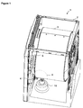
Figure 1 - is the schematic view of a laundry dryer. -
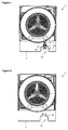
Figure 2 - is the view of detail A inFigure 1 when the transportation safety member is in the first position. -
Figure 3 - is the view of detail A inFigure 1 when the transportation safety member is in the second position. -
Figure 4 - is the schematic view of a drum and a transportation safety member when the transportation safety member is in the first position in an embodiment of the present invention. -
Figure 5 - is the schematic view of a guide in an embodiment of the present invention. - The elements illustrated in the figures are numbered as follows:
- 1.
- Laundry dryer
- 2.
- Body
- 3.
- Drum
- 4.
- Roller
- 5.
- Frame
- 6.
- Transportation safety member
- 7.
- Shaft
- 8.
- Resting member
- 9.
- Head
- 10.
- Guide
- 11.
- Stopper
- 12.
- Opening
- The laundry dryer (1) comprises
- a body (2),
- a drum (3) which rotates around the horizontal axis and wherein items to be dried are placed,
- more than one roller (4) whereon the drum (3) is seated and which supports the drum (3) by rotating around their own axes by the movement of the drum (3) during the drying process, and
- a frame (5) whereon the rollers (4) are rotatably mounted.
- The laundry dryer (1) of the present invention comprises a transportation safety member (6) which has a first position wherein it does not contact the drum (3) and a second position wherein it contacts the drum (3) by being moved and provides the contact of the drum (3) with the rollers (4) to be broken (
Figure 1 ). - When the laundry dryer (1) is to be transported, in order to provide the safety of the laundry dryer (1), the position of the transportation safety member (6) is changed so as to provide a certain distance (D) between the drum (3) and the rollers (4). The user first positions the laundry dryer (1) so as to allow access to the transportation safety member (6) and then provides the movement of the transportation safety member (6) inside the laundry dryer (1) by moving the transportation safety member (6). After the transportation safety member (6) contacts the drum (3) and separates the drum (3) from the rollers (4) as much as a certain distance (D), the laundry dryer (1) becomes ready for the transportation process (
Figure 3 ). - When the laundry dryer (1) reaches the place to be transported, the transportation safety member (6) is changed from the second position to the first position. In this position, the drum (3) contacts the rollers (4). The laundry dryer (1) is positioned such that the transportation safety member (6) can be reached and then, by moving the transportation safety member (6), the drum (3) is provided to be seated onto the rollers (4) by means of the transportation safety member (6) (
Figure 2 ). - In an embodiment of the present invention, the laundry dryer (1) comprises the transportation safety member (6) which moves the drum (3) upwards while being brought from the first position to the second position. Thus, the drum (3) is lifted upwards during transportation and by breaking the contact of the drum (3) with the rollers (4) damages that may occur if the laundry dryer (1) falls down are prevented.
- In an embodiment of the present invention, the transportation safety member (6) comprises a screw-shaped shaft (7) extending from the body (2) towards the drum (3), a resting member (8) which is located at the shaft (7) end facing the drum (3) and contacts the drum (3) when the transportation safety member (6) is in the second position, and a head (9) which is located at the lower end of the shaft (7) and allows the shaft (7) to be rotated. Thus, the pressure acting on the drum (3) by the resting member (8) is reduced and the drum (3) is prevented from being deformed due to the force applied onto the drum (3), and the distance between the transportation safety member (6) and the drum (3) is adjusted by means of the head (9) (
Figure 4 ). - In a derivative of this embodiment, the transportation safety member (6) comprises a resting member (8) having the same shape as the portion it contacts the drum (3). Thus, the resting member (8) uniformly contacts the drum (3).
- In a derivative of this embodiment, the laundry dryer (1) comprises the transportation safety member (6) which has a resting member (8) produced from elastomeric material. By means of the elastomeric material, the drum (3) is not damaged at the moment the resting member (8) contacts the drum (3), for example, in case that the drum (3) moves and falls down onto the resting member (8) during transportation.
- In an embodiment of the present invention, the laundry dryer (1) comprises a guide (10) which is located between the body (2) and the drum (3) and has a screw hole providing the shaft (7) of the transportation safety member (6) to be borne. Thus, the screw-shaped shaft (7) can be moved inside the guide (10) in the desired distance (
Figure 4, Figure 5 ). - In a derivative of this embodiment, the laundry dryer (1) comprises a stopper (11) which is located on the guide (10) and prevents the shaft (7) from leaving the guide (10) after the shaft (7) moves towards the drum (3), and the transportation safety member (6) which has a head (9) having a diameter greater than that of the shaft (7) so as to allow the transportation safety member (6) to be stopped by bearing against the stopper (11). Thus, the movement of the transportation safety member (6) inside the guide (10) is limited after the drum (3) is separated from the rollers (4) and the drum (3) is prevented from hitting the upper surface of the frame (5) (
Figure 4 ). - In a derivative of this embodiment, the laundry dryer (1) comprises an opening (12) which is arranged on the body (2) at the level of the guide (10) and allows the transportation safety member (6) to be placed into the guide (10). Thus, the position of the transportation safety member (6) can be changed by reaching into the guide (10) through the opening (12).
- In a derivative of this embodiment, the laundry dryer (1) comprises the guide (10) which is positioned near one of the front corners of the body base (T). Thus, the transportation safety member (6) can be reached easily by bringing the laundry dryer (1) to a half-angled position.
- In a derivative of this embodiment, the laundry dryer (1) comprises two guides (10) located near the front corners of the body base (T) and two transportation safety members (6) mounted to the guides (10). Thus, it is possible to lift the drum (3) in a balanced manner and separate it from the rollers (4).
- The laundry dryer (1) of the present invention comprises a transportation safety member (6) that can have two positions. By changing the transportation safety member (6) to the second position, the drum (3) is separated from the rollers (4) it is seated on. Thus, the safety of the laundry dryer (1) during transportation is provided.
- It is to be understood that the present invention is not limited to the embodiments disclosed above and a person skilled in the art can easily introduce different embodiments. These should be considered within the scope of the protection postulated by the claims of the present invention.
Claims (10)
- A laundry dryer (1) comprising- a body (2),- a drum (3) which rotates around the horizontal axis and wherein items to be dried are placed,- more than one roller (4) whereon the drum (3) is seated and which support the drum (3) by rotating around their own axes by the movement of the drum (3) during the drying process, and- a frame (5) whereon the rollers (4) are rotatably mounted,
characterized by- a transportation safety member (6) which has a first position wherein it does not contact the drum (3) and a second position wherein it contacts the drum (3) by being moved and provides the contact of the drum (3) with the rollers (4) to be broken - A laundry dryer (1) as in Claim 1, characterized by the transportation safety member (6) which moves the drum (3) upwards while being brought from the first position to the second position.
- A laundry dryer (1) as in any one of the above claims, characterized by the transportation safety member (6) that comprises a shaft (7) which extends from the body (2) towards the drum (3), a resting member (8) which is located at the shaft (7) end facing the drum (3) and contacts the drum (3) when the transportation safety member (6) is in the second position, and a head (9) which is located at the lower end of the shaft (7) and allows the shaft (7) to be rotated.
- A laundry dryer (1) as in Claim 3, characterized by the transportation safety member (6) which comprises a resting member (8) having the same shape as the portion of the drum, where it contacts the drum (3).
- A laundry dryer (1) as in Claim 3 or 4, characterized by the transportation safety member (6) which comprises a resting member (8) produced from elastomeric material.
- A laundry dryer (1) as in any one of the above claims, characterized by a guide (10) which is located between the body (2) and the drum (3) and has a screw hole providing the transportation safety member (6) to be borne.
- A laundry dryer (1) as in Claim 6, characterized by a stopper (11) which is located on the guide (10) and prevents the shaft (7) from leaving the guide (10) after the shaft (7) moves towards the drum (3), and the transportation safety member (6) which has the head (9) having a diameter greater than that of the shaft (7) so as to allow the transportation safety member (6) to be stopped by bearing against the stopper (11).
- A laundry dryer (1) as in Claim 6 or 7, characterized by an opening (12) which is arranged on the body (2) at the level of the guide (10) and allows the transportation safety member (6) to be placed into the guide (10).
- A laundry dryer (1) as in any one of the Claims 6 to 8, characterized by the guide (10) which is positioned near one of the front corners of the body base (T).
- A laundry dryer (1) as in any one of the Claims 6 to 9, characterized by two guides (10) which are located near the front corners of the body base (T).
Applications Claiming Priority (2)
| Application Number | Priority Date | Filing Date | Title |
|---|---|---|---|
| TR201111061 | 2011-11-04 | ||
| PCT/EP2012/071617 WO2013064568A1 (en) | 2011-11-04 | 2012-10-31 | A laundry dryer comprising a transportation safety member |
Publications (2)
| Publication Number | Publication Date |
|---|---|
| EP2773806A1 EP2773806A1 (en) | 2014-09-10 |
| EP2773806B1 true EP2773806B1 (en) | 2016-02-03 |
Family
ID=47216225
Family Applications (1)
| Application Number | Title | Priority Date | Filing Date |
|---|---|---|---|
| EP12788478.1A Not-in-force EP2773806B1 (en) | 2011-11-04 | 2012-10-31 | A laundry dryer comprising a transportation safety member |
Country Status (2)
| Country | Link |
|---|---|
| EP (1) | EP2773806B1 (en) |
| WO (1) | WO2013064568A1 (en) |
Cited By (1)
| Publication number | Priority date | Publication date | Assignee | Title |
|---|---|---|---|---|
| EP3470568A1 (en) | 2017-10-13 | 2019-04-17 | BSH Hausgeräte GmbH | Dryer with a safety device for protection against damage as a result of shock and method for the operation of same |
Families Citing this family (2)
| Publication number | Priority date | Publication date | Assignee | Title |
|---|---|---|---|---|
| PL3124671T3 (en) * | 2015-07-27 | 2023-01-02 | Electrolux Appliances Aktiebolag | Laundry dryer |
| CN108411554B (en) * | 2018-02-26 | 2020-07-28 | 郝影 | Horizontal washing machine |
Family Cites Families (4)
| Publication number | Priority date | Publication date | Assignee | Title |
|---|---|---|---|---|
| IT8334041V0 (en) * | 1983-09-02 | 1983-09-02 | Zanussi A Spa Industrie | SUPPORT AND HOLDING DEVICE FOR THE DRYER BASKET. |
| IT216704Z2 (en) * | 1989-06-23 | 1991-09-19 | Ocean Spa | DRYING MACHINE PERFECTED IN PARTICULAR FOR LINEN. |
| TR200603230T1 (en) | 2003-12-26 | 2007-01-22 | Ar�El�K Anon�M ��Rket� | A washer / dryer. |
| DE102005009230B4 (en) * | 2005-02-25 | 2008-12-24 | Jensen-Senking Gmbh | Drying plant with a dryer seal and centering means |
-
2012
- 2012-10-31 WO PCT/EP2012/071617 patent/WO2013064568A1/en not_active Ceased
- 2012-10-31 EP EP12788478.1A patent/EP2773806B1/en not_active Not-in-force
Cited By (2)
| Publication number | Priority date | Publication date | Assignee | Title |
|---|---|---|---|---|
| EP3470568A1 (en) | 2017-10-13 | 2019-04-17 | BSH Hausgeräte GmbH | Dryer with a safety device for protection against damage as a result of shock and method for the operation of same |
| DE102017218361A1 (en) | 2017-10-13 | 2019-04-18 | BSH Hausgeräte GmbH | Dryer with a safety device to protect against damage in case of impact and method of its operation |
Also Published As
| Publication number | Publication date |
|---|---|
| EP2773806A1 (en) | 2014-09-10 |
| WO2013064568A1 (en) | 2013-05-10 |
Similar Documents
| Publication | Publication Date | Title |
|---|---|---|
| EP2773806B1 (en) | A laundry dryer comprising a transportation safety member | |
| KR101197659B1 (en) | apparatus for reversing aluminium alloy plate | |
| KR101271786B1 (en) | Apparatus for Transferring Coil-Type Steel Sheet | |
| KR20110047040A (en) | Injury prevention device of belt member | |
| KR20130101788A (en) | Gripping apparatus for transferring | |
| KR20140056581A (en) | Apparatus for centering belt of belt conveyer | |
| TW201332408A (en) | Vertical transfer jig and apparatus for wet treatment using the same | |
| KR100845188B1 (en) | Textile tumbler machine | |
| TW200531902A (en) | Retention device for a conveyor roller and the conveyor | |
| KR100967489B1 (en) | Wire rod feeder | |
| KR20120072479A (en) | Belt conveyor | |
| KR100822343B1 (en) | Stone processing equipment | |
| KR101433609B1 (en) | basket for coating and drying | |
| KR101067847B1 (en) | Cylindrical molding machine | |
| KR101097042B1 (en) | Apparatus for Substrate Processing | |
| KR20090053981A (en) | Display Board Feeder | |
| KR101242803B1 (en) | Apparatus for supporting coil-type steel sheet | |
| KR100633114B1 (en) | Automatic dispenser | |
| KR101366176B1 (en) | Apparatus for detecting a bad-winded steel coil | |
| CN101652511A (en) | Washer / dryer with support means to protect internals during transport | |
| KR20110130670A (en) | Slip prevention device | |
| CN108217149A (en) | A kind of switching mechanism | |
| KR20090054234A (en) | Belt rolling prevention device of belt conveyor | |
| KR200373853Y1 (en) | Automatic dividing apparatus | |
| KR102360391B1 (en) | Apparatus for preventing leaned loading of stacker |
Legal Events
| Date | Code | Title | Description |
|---|---|---|---|
| PUAI | Public reference made under article 153(3) epc to a published international application that has entered the european phase |
Free format text: ORIGINAL CODE: 0009012 |
|
| 17P | Request for examination filed |
Effective date: 20140319 |
|
| AK | Designated contracting states |
Kind code of ref document: A1 Designated state(s): AL AT BE BG CH CY CZ DE DK EE ES FI FR GB GR HR HU IE IS IT LI LT LU LV MC MK MT NL NO PL PT RO RS SE SI SK SM TR |
|
| DAX | Request for extension of the european patent (deleted) | ||
| GRAP | Despatch of communication of intention to grant a patent |
Free format text: ORIGINAL CODE: EPIDOSNIGR1 |
|
| INTG | Intention to grant announced |
Effective date: 20150817 |
|
| GRAS | Grant fee paid |
Free format text: ORIGINAL CODE: EPIDOSNIGR3 |
|
| GRAA | (expected) grant |
Free format text: ORIGINAL CODE: 0009210 |
|
| AK | Designated contracting states |
Kind code of ref document: B1 Designated state(s): AL AT BE BG CH CY CZ DE DK EE ES FI FR GB GR HR HU IE IS IT LI LT LU LV MC MK MT NL NO PL PT RO RS SE SI SK SM TR |
|
| REG | Reference to a national code |
Ref country code: GB Ref legal event code: FG4D |
|
| REG | Reference to a national code |
Ref country code: AT Ref legal event code: REF Ref document number: 773770 Country of ref document: AT Kind code of ref document: T Effective date: 20160215 Ref country code: CH Ref legal event code: EP |
|
| REG | Reference to a national code |
Ref country code: IE Ref legal event code: FG4D |
|
| REG | Reference to a national code |
Ref country code: DE Ref legal event code: R096 Ref document number: 602012014487 Country of ref document: DE |
|
| REG | Reference to a national code |
Ref country code: LT Ref legal event code: MG4D Ref country code: NL Ref legal event code: MP Effective date: 20160203 |
|
| REG | Reference to a national code |
Ref country code: AT Ref legal event code: MK05 Ref document number: 773770 Country of ref document: AT Kind code of ref document: T Effective date: 20160203 |
|
| PG25 | Lapsed in a contracting state [announced via postgrant information from national office to epo] |
Ref country code: NO Free format text: LAPSE BECAUSE OF FAILURE TO SUBMIT A TRANSLATION OF THE DESCRIPTION OR TO PAY THE FEE WITHIN THE PRESCRIBED TIME-LIMIT Effective date: 20160503 Ref country code: IT Free format text: LAPSE BECAUSE OF FAILURE TO SUBMIT A TRANSLATION OF THE DESCRIPTION OR TO PAY THE FEE WITHIN THE PRESCRIBED TIME-LIMIT Effective date: 20160203 Ref country code: FI Free format text: LAPSE BECAUSE OF FAILURE TO SUBMIT A TRANSLATION OF THE DESCRIPTION OR TO PAY THE FEE WITHIN THE PRESCRIBED TIME-LIMIT Effective date: 20160203 Ref country code: HR Free format text: LAPSE BECAUSE OF FAILURE TO SUBMIT A TRANSLATION OF THE DESCRIPTION OR TO PAY THE FEE WITHIN THE PRESCRIBED TIME-LIMIT Effective date: 20160203 Ref country code: GR Free format text: LAPSE BECAUSE OF FAILURE TO SUBMIT A TRANSLATION OF THE DESCRIPTION OR TO PAY THE FEE WITHIN THE PRESCRIBED TIME-LIMIT Effective date: 20160504 Ref country code: ES Free format text: LAPSE BECAUSE OF FAILURE TO SUBMIT A TRANSLATION OF THE DESCRIPTION OR TO PAY THE FEE WITHIN THE PRESCRIBED TIME-LIMIT Effective date: 20160203 |
|
| PG25 | Lapsed in a contracting state [announced via postgrant information from national office to epo] |
Ref country code: RS Free format text: LAPSE BECAUSE OF FAILURE TO SUBMIT A TRANSLATION OF THE DESCRIPTION OR TO PAY THE FEE WITHIN THE PRESCRIBED TIME-LIMIT Effective date: 20160203 Ref country code: NL Free format text: LAPSE BECAUSE OF FAILURE TO SUBMIT A TRANSLATION OF THE DESCRIPTION OR TO PAY THE FEE WITHIN THE PRESCRIBED TIME-LIMIT Effective date: 20160203 Ref country code: PT Free format text: LAPSE BECAUSE OF FAILURE TO SUBMIT A TRANSLATION OF THE DESCRIPTION OR TO PAY THE FEE WITHIN THE PRESCRIBED TIME-LIMIT Effective date: 20160603 Ref country code: LV Free format text: LAPSE BECAUSE OF FAILURE TO SUBMIT A TRANSLATION OF THE DESCRIPTION OR TO PAY THE FEE WITHIN THE PRESCRIBED TIME-LIMIT Effective date: 20160203 Ref country code: LT Free format text: LAPSE BECAUSE OF FAILURE TO SUBMIT A TRANSLATION OF THE DESCRIPTION OR TO PAY THE FEE WITHIN THE PRESCRIBED TIME-LIMIT Effective date: 20160203 Ref country code: AT Free format text: LAPSE BECAUSE OF FAILURE TO SUBMIT A TRANSLATION OF THE DESCRIPTION OR TO PAY THE FEE WITHIN THE PRESCRIBED TIME-LIMIT Effective date: 20160203 Ref country code: IS Free format text: LAPSE BECAUSE OF FAILURE TO SUBMIT A TRANSLATION OF THE DESCRIPTION OR TO PAY THE FEE WITHIN THE PRESCRIBED TIME-LIMIT Effective date: 20160603 Ref country code: PL Free format text: LAPSE BECAUSE OF FAILURE TO SUBMIT A TRANSLATION OF THE DESCRIPTION OR TO PAY THE FEE WITHIN THE PRESCRIBED TIME-LIMIT Effective date: 20160203 Ref country code: SE Free format text: LAPSE BECAUSE OF FAILURE TO SUBMIT A TRANSLATION OF THE DESCRIPTION OR TO PAY THE FEE WITHIN THE PRESCRIBED TIME-LIMIT Effective date: 20160203 |
|
| PGFP | Annual fee paid to national office [announced via postgrant information from national office to epo] |
Ref country code: TR Payment date: 20160503 Year of fee payment: 5 |
|
| REG | Reference to a national code |
Ref country code: FR Ref legal event code: PLFP Year of fee payment: 5 |
|
| PG25 | Lapsed in a contracting state [announced via postgrant information from national office to epo] |
Ref country code: EE Free format text: LAPSE BECAUSE OF FAILURE TO SUBMIT A TRANSLATION OF THE DESCRIPTION OR TO PAY THE FEE WITHIN THE PRESCRIBED TIME-LIMIT Effective date: 20160203 Ref country code: DK Free format text: LAPSE BECAUSE OF FAILURE TO SUBMIT A TRANSLATION OF THE DESCRIPTION OR TO PAY THE FEE WITHIN THE PRESCRIBED TIME-LIMIT Effective date: 20160203 |
|
| REG | Reference to a national code |
Ref country code: DE Ref legal event code: R097 Ref document number: 602012014487 Country of ref document: DE |
|
| PG25 | Lapsed in a contracting state [announced via postgrant information from national office to epo] |
Ref country code: RO Free format text: LAPSE BECAUSE OF FAILURE TO SUBMIT A TRANSLATION OF THE DESCRIPTION OR TO PAY THE FEE WITHIN THE PRESCRIBED TIME-LIMIT Effective date: 20160203 Ref country code: CZ Free format text: LAPSE BECAUSE OF FAILURE TO SUBMIT A TRANSLATION OF THE DESCRIPTION OR TO PAY THE FEE WITHIN THE PRESCRIBED TIME-LIMIT Effective date: 20160203 Ref country code: SK Free format text: LAPSE BECAUSE OF FAILURE TO SUBMIT A TRANSLATION OF THE DESCRIPTION OR TO PAY THE FEE WITHIN THE PRESCRIBED TIME-LIMIT Effective date: 20160203 Ref country code: SM Free format text: LAPSE BECAUSE OF FAILURE TO SUBMIT A TRANSLATION OF THE DESCRIPTION OR TO PAY THE FEE WITHIN THE PRESCRIBED TIME-LIMIT Effective date: 20160203 |
|
| PLBE | No opposition filed within time limit |
Free format text: ORIGINAL CODE: 0009261 |
|
| STAA | Information on the status of an ep patent application or granted ep patent |
Free format text: STATUS: NO OPPOSITION FILED WITHIN TIME LIMIT |
|
| PG25 | Lapsed in a contracting state [announced via postgrant information from national office to epo] |
Ref country code: BE Free format text: LAPSE BECAUSE OF FAILURE TO SUBMIT A TRANSLATION OF THE DESCRIPTION OR TO PAY THE FEE WITHIN THE PRESCRIBED TIME-LIMIT Effective date: 20160203 |
|
| 26N | No opposition filed |
Effective date: 20161104 |
|
| PGFP | Annual fee paid to national office [announced via postgrant information from national office to epo] |
Ref country code: GB Payment date: 20161020 Year of fee payment: 5 Ref country code: DE Payment date: 20161020 Year of fee payment: 5 Ref country code: FR Payment date: 20161020 Year of fee payment: 5 |
|
| PG25 | Lapsed in a contracting state [announced via postgrant information from national office to epo] |
Ref country code: SI Free format text: LAPSE BECAUSE OF FAILURE TO SUBMIT A TRANSLATION OF THE DESCRIPTION OR TO PAY THE FEE WITHIN THE PRESCRIBED TIME-LIMIT Effective date: 20160203 Ref country code: BG Free format text: LAPSE BECAUSE OF FAILURE TO SUBMIT A TRANSLATION OF THE DESCRIPTION OR TO PAY THE FEE WITHIN THE PRESCRIBED TIME-LIMIT Effective date: 20160503 |
|
| REG | Reference to a national code |
Ref country code: CH Ref legal event code: PL |
|
| REG | Reference to a national code |
Ref country code: IE Ref legal event code: MM4A |
|
| PG25 | Lapsed in a contracting state [announced via postgrant information from national office to epo] |
Ref country code: LI Free format text: LAPSE BECAUSE OF NON-PAYMENT OF DUE FEES Effective date: 20161031 Ref country code: CH Free format text: LAPSE BECAUSE OF NON-PAYMENT OF DUE FEES Effective date: 20161031 |
|
| PG25 | Lapsed in a contracting state [announced via postgrant information from national office to epo] |
Ref country code: LU Free format text: LAPSE BECAUSE OF NON-PAYMENT OF DUE FEES Effective date: 20161031 |
|
| PG25 | Lapsed in a contracting state [announced via postgrant information from national office to epo] |
Ref country code: IE Free format text: LAPSE BECAUSE OF NON-PAYMENT OF DUE FEES Effective date: 20161031 |
|
| REG | Reference to a national code |
Ref country code: DE Ref legal event code: R119 Ref document number: 602012014487 Country of ref document: DE |
|
| PG25 | Lapsed in a contracting state [announced via postgrant information from national office to epo] |
Ref country code: HU Free format text: LAPSE BECAUSE OF FAILURE TO SUBMIT A TRANSLATION OF THE DESCRIPTION OR TO PAY THE FEE WITHIN THE PRESCRIBED TIME-LIMIT; INVALID AB INITIO Effective date: 20121031 |
|
| GBPC | Gb: european patent ceased through non-payment of renewal fee |
Effective date: 20171031 |
|
| PG25 | Lapsed in a contracting state [announced via postgrant information from national office to epo] |
Ref country code: MK Free format text: LAPSE BECAUSE OF FAILURE TO SUBMIT A TRANSLATION OF THE DESCRIPTION OR TO PAY THE FEE WITHIN THE PRESCRIBED TIME-LIMIT Effective date: 20160203 Ref country code: MC Free format text: LAPSE BECAUSE OF FAILURE TO SUBMIT A TRANSLATION OF THE DESCRIPTION OR TO PAY THE FEE WITHIN THE PRESCRIBED TIME-LIMIT Effective date: 20160203 Ref country code: MT Free format text: LAPSE BECAUSE OF NON-PAYMENT OF DUE FEES Effective date: 20161031 Ref country code: CY Free format text: LAPSE BECAUSE OF FAILURE TO SUBMIT A TRANSLATION OF THE DESCRIPTION OR TO PAY THE FEE WITHIN THE PRESCRIBED TIME-LIMIT Effective date: 20160203 |
|
| REG | Reference to a national code |
Ref country code: FR Ref legal event code: ST Effective date: 20180629 |
|
| PG25 | Lapsed in a contracting state [announced via postgrant information from national office to epo] |
Ref country code: DE Free format text: LAPSE BECAUSE OF NON-PAYMENT OF DUE FEES Effective date: 20180501 Ref country code: GB Free format text: LAPSE BECAUSE OF NON-PAYMENT OF DUE FEES Effective date: 20171031 |
|
| PG25 | Lapsed in a contracting state [announced via postgrant information from national office to epo] |
Ref country code: FR Free format text: LAPSE BECAUSE OF NON-PAYMENT OF DUE FEES Effective date: 20171031 |
|
| PG25 | Lapsed in a contracting state [announced via postgrant information from national office to epo] |
Ref country code: AL Free format text: LAPSE BECAUSE OF FAILURE TO SUBMIT A TRANSLATION OF THE DESCRIPTION OR TO PAY THE FEE WITHIN THE PRESCRIBED TIME-LIMIT Effective date: 20160203 |
|
| PG25 | Lapsed in a contracting state [announced via postgrant information from national office to epo] |
Ref country code: TR Free format text: LAPSE BECAUSE OF NON-PAYMENT OF DUE FEES Effective date: 20171031 |