EP2775349A1 - A method for determining an in-focus position and a vision inspection system - Google Patents
A method for determining an in-focus position and a vision inspection system Download PDFInfo
- Publication number
- EP2775349A1 EP2775349A1 EP14171189.5A EP14171189A EP2775349A1 EP 2775349 A1 EP2775349 A1 EP 2775349A1 EP 14171189 A EP14171189 A EP 14171189A EP 2775349 A1 EP2775349 A1 EP 2775349A1
- Authority
- EP
- European Patent Office
- Prior art keywords
- image data
- features
- sample
- image
- determined
- Prior art date
- Legal status (The legal status is an assumption and is not a legal conclusion. Google has not performed a legal analysis and makes no representation as to the accuracy of the status listed.)
- Granted
Links
Images





Classifications
-
- G—PHYSICS
- G03—PHOTOGRAPHY; CINEMATOGRAPHY; ANALOGOUS TECHNIQUES USING WAVES OTHER THAN OPTICAL WAVES; ELECTROGRAPHY; HOLOGRAPHY
- G03B—APPARATUS OR ARRANGEMENTS FOR TAKING PHOTOGRAPHS OR FOR PROJECTING OR VIEWING THEM; APPARATUS OR ARRANGEMENTS EMPLOYING ANALOGOUS TECHNIQUES USING WAVES OTHER THAN OPTICAL WAVES; ACCESSORIES THEREFOR
- G03B13/00—Viewfinders; Focusing aids for cameras; Means for focusing for cameras; Autofocus systems for cameras
- G03B13/32—Means for focusing
-
- G—PHYSICS
- G06—COMPUTING OR CALCULATING; COUNTING
- G06T—IMAGE DATA PROCESSING OR GENERATION, IN GENERAL
- G06T7/00—Image analysis
- G06T7/10—Segmentation; Edge detection
- G06T7/11—Region-based segmentation
-
- G—PHYSICS
- G06—COMPUTING OR CALCULATING; COUNTING
- G06T—IMAGE DATA PROCESSING OR GENERATION, IN GENERAL
- G06T7/00—Image analysis
- G06T7/90—Determination of colour characteristics
-
- G—PHYSICS
- G06—COMPUTING OR CALCULATING; COUNTING
- G06V—IMAGE OR VIDEO RECOGNITION OR UNDERSTANDING
- G06V20/00—Scenes; Scene-specific elements
- G06V20/60—Type of objects
- G06V20/69—Microscopic objects, e.g. biological cells or cellular parts
- G06V20/693—Acquisition
-
- G—PHYSICS
- G06—COMPUTING OR CALCULATING; COUNTING
- G06T—IMAGE DATA PROCESSING OR GENERATION, IN GENERAL
- G06T2207/00—Indexing scheme for image analysis or image enhancement
- G06T2207/30—Subject of image; Context of image processing
- G06T2207/30004—Biomedical image processing
- G06T2207/30024—Cell structures in vitro; Tissue sections in vitro
Definitions
- the present invention generally relates to a method for determining a difference between a sample position and an in-focus position, a vision inspection system and a control device.
- Computer-aided image analysis of biological material has become popular during the last years. For instance, computer-aided processes for counting and classifying white blood cells in a blood smear have been developed. These types of tests are e.g. an important step in the process of determining whether a patient suffers from an infection, allergy or blood cancer.
- the image data is of proper quality, involving for instance that the image data is sharp, i.e. captured with accurate focus settings.
- a common method for finding an in-focus position involves a first step of capturing several images at different positions, a second step of identifying high frequency components in the captured images and a third step of determining the image with the highest amount of high frequency components.
- the position corresponding to the image with the highest amount of high frequency components is thereafter chosen to be the in-focus position. In order to find the in-focus position it is not unlikely that as much as 20 images at different positions have to be captured.
- the image capturing process must be repeated a number of times, e.g. 20 times, for every object, which in turn implies that a large amount of image data has to be captured for every sample and that the vision inspection system must be readjusted a large number of times for every sample.
- this method consumes a lot of time and the large amount of readjustments may wear out the system.
- an objective of the invention is to solve or at least reduce the problems discussed above.
- an objective is to provide a method for determining a difference between a sample position and an in-focus position based upon image data. This implies that fewer images have to be captured in order to determine an in-focus position, and in many cases only one image is needed. By reducing the number of images the processing time will be reduced as well as the risk of wearing out the steering motor system.
- the above object is provided according to a first aspect by a method for determining a difference between a sample position and an in-focus position, said method comprising capturing image data depicting a sample, extracting a feature set from said captured image data, and classifying, by using a machine learning algorithm that is trained to associate image data features to a position difference value, said feature set into said position difference value, wherein said position difference value corresponds to said difference.
- said feature set may comprise a sub-set of contrast features.
- said sub-set of contrast features may be selected from a group consisting of a squared gradient function based upon said image data, a wavelet function based upon said image data and an auto-correlation function, such as Vollath's F 4 function or a combination of Vollath's F 4 function and Vollath's F 5 function, based upon said image data, a variance for the whole image data and a Laplace-based focus measure.
- a squared gradient function based upon said image data
- a wavelet function based upon said image data
- an auto-correlation function such as Vollath's F 4 function or a combination of Vollath's F 4 function and Vollath's F 5 function
- said contrast features may be determined for a plurality of color layers.
- said contrast features may be determined for a sub-set of said image data.
- said feature set may comprise a sub-set of directional features.
- a number of features of said sub-set of directional features may be determined by identifying differences between a plurality of color layers and determining at least one feature value based upon said determined differences.
- a number of features of said sub-set of directional features may be determined by identifying a number of different objects having different heights in said sample, determining differences for said different objects, and determining at least one feature value based upon said determined differences for said different objects.
- said sub-set of directional features may comprise a quotient between different Laplace-based focus measures according to the formula F A m , c ⁇ 1 R ⁇ F A q , c ⁇ 2 R F A n , c ⁇ 1 R ⁇ F A p , c ⁇ 2 R .
- said directional features may be determined for a sub-set of said image data.
- said feature set may comprise a sub-set of content features.
- said sub-set of content features may comprise overall content features and segmental content features.
- said overall content features may be selected from a group consisting of mean intensity for the whole image data and variance for the whole image data.
- said overall content features may be determined for a plurality of color layers.
- the method may further comprise determining foreground and background segments in said image data.
- the method may further comprise segmenting said foreground segment into segments of object classes.
- the method may further comprise determining a number of objects in at least one of said object classes.
- the method may further comprise determining a number of pixels belonging to the objects of an object class for at least one of said object classes.
- said segmental content features may be selected from a group consisting of mean intensity for foreground segments, mean intensity for background segments, variance for foreground segments, variance for background segments and an area function expressing an area distribution between different segments.
- said segmental content features may be selected from a group consisting of mean intensity for at least one of said object classes, variance for for at least one of said object classes and an area function expressing an area distribution between different object classes.
- At least one of said object classes may be selected from a group consisting of a red blood cell (RBC) object class and a white blood cell (WBC) object class.
- RBC red blood cell
- WBC white blood cell
- said foreground and background segments may be determined for a plurality of color layers.
- the area function may for instance be a function that expresses the relationship between foreground segments and background segments, such as a number of foreground segments pixels divided by a number of background segment pixels.
- the main purpose of the content features is to compensate for variations in the image that do not influence the degree/level of focus, but still influence the contrast features and directional features.
- said step of classifying said feature set into a position difference value may be performed by a support vector machine.
- a vision inspection system comprising a slide holder adapted to hold at least one slide comprising a sample, an image capturing device configured to capture image data depicting said sample, wherein said image capturing device comprises an optical system and an image sensor, a steering motor system configured to alter a distance between said sample and said optical system, a processor connected to said image capturing device and said steering motor system, wherein said processor, in association with a memory, is configured to determine a difference between a sample position and an in-focus position by receiving said image data depicting said sample from said image capturing device, extracting a feature set from said image data, classifying, by using a machine learning algorithm that is trained to associate image data features to a position difference value, said feature set into said position difference value, wherein said position difference value corresponds to said difference and instructing said steering motor system to alter said distance between said sample and said optical system in accordance to said determined difference.
- said feature set may comprise a sub-set of contrast features.
- said sub-set of contrast features may be selected from a group consisting of a squared gradient function based upon said image data, a wavelet function based upon said image data and an auto-correlation function, such as Vollath's F 4 function or a combination of Vollath's F 4 function and Vollath's F 5 function, based upon said image data, a variance for the whole image data and a Laplace-based focus measure.
- a squared gradient function based upon said image data
- a wavelet function based upon said image data
- an auto-correlation function such as Vollath's F 4 function or a combination of Vollath's F 4 function and Vollath's F 5 function
- said feature set may comprise a sub-set of directional features.
- a number of features of said sub-set of directional features may be determined by identifying differences between a plurality of color layers and determining at least one feature value based upon said determined differences.
- said sub-set of directional features may comprise a quotient between different Laplace-based focus measures according to the formula F A m , c ⁇ 1 R ⁇ F A q , c ⁇ 2 R F A n , c ⁇ 1 R ⁇ F A p , c ⁇ 2 R .
- said feature set may comprise a sub-set of content features.
- said features may be determined for a plurality of color layers.
- said features may be determined for a sub-set of said image data.
- said step of classifying said feature set into a position difference value may be performed by a support vector machine.
- a control device comprising a receiver configured to receive image data depicting said sample, a processor, in association with a memory, configured to determine a difference between a sample position and an in-focus position by extracting a feature set from said image data, classifying, by using a machine learning algorithm that is trained to associate image data features to a position difference value, said feature set into said position difference value, wherein said position difference value corresponds to said difference and a transmitter configured to transmit said determined difference.
- the above object is provided according to a fourth aspect by a computer program comprising software instructions arranged to be perform the method as described above when downloaded and run in an apparatus.
- Fig 1 generally illustrates a vision inspection system 100.
- a slide 102 comprising a sample, such as a blood sample, is placed in a slide holder 104.
- the slide holder 104 may be adapted to hold a number of slides or only one, as illustrated in fig 1 .
- An image capturing device 106 comprising an optical system 108 and an image sensor 110, is adapted to capture image data depicting the sample in the slide 102.
- a light emitting device (not shown) may be used.
- the image data captured by the image capturing device 106 can be transferred to an image processing device 112.
- the image processing device 112 may be an external apparatus, such as a personal computer, connected to the image capturing device 106. Alternatively, the image processing device 112 may be incorporated in the image capturing device 106.
- the image processing device 112 can comprise a processor 114, associated with a memory 116, configured to determine a difference between a sample position and an in-focus position. This process is further illustrated in fig 8 .
- an instruction can be transferred to a steering motor system 118.
- the steering motor system 118 can, based upon the instruction from the image processing device 112, alter the distance z between the slide 102 and the optical system 108.
- a method for inspecting samples by using the vision inspection system is generally illustrated in fig 2 .
- the vision inspection system can be loaded with one or several slides. Each slide holds a sample.
- a sample may be, but is not restricted to, a biological specimen.
- a first slide of the one or several slides is analyzed. This can be performed by moving the slide holder such that the first slide is in the field of view of the image capturing device. Alternatively, the image capturing device can be moved such that the first slide is in the field of view of the image capturing device.
- a number of objects such as white blood cells, to be analysed in further detail is recognized.
- the position of the objects can be stored.
- a fourth step 206 object image data is captured for each detected object.
- the slide holder can be moved in accordance to the stored positions.
- the image capturing device may be moved in accordance to the stored positions.
- the object image data can be pre-classified into a pre-determined classification. For instance, if the objects are white blood cells, this step may comprise classifying the white blood cells into a specific type of white blood cells.
- the object image data and associated pre-classications can be stored.
- the operator of the vision inspection system investigate image data depicting the objects for each sample together with associated pre-classifications.
- the second step 202 to the sixth step 210 can be repeated for the other slides of the vision inspection system.
- a slide overall image may be captured.
- the magnification of the image capturing device when capturing the slide overall image, may be 10X, i.e. ten times enlargement, and when capturing object image data the magnification of the image capturing device may be switched to 100X, i.e. hundreds times enlargement.
- the magnification may vary for different systems, but generally the magnification of the image capturing device is increased when switching from capturing the slide overall image to capturing the object image data.
- the optical system can be moved in order to capture image data depicting each of the detected objects in the sample.
- the slide is to be placed in an in-focus position, which means that the distance z between the slide and the optical system is to be equal to, or at least close to, the focal distance f. If the distance z is greater than the focal distance f, the system may be said to be positively defocused, and vice versa, if the distance z is less than the focal distance f, the system may be said to be negatively defocused.
- the sample for instance, is a blood sample
- the sample may be smeared onto the slide. This may imply that the sample is not fully plain, which in turn implies that the difference between the distance z and the focal distance f is to be determined each time new object image data is to be captured.
- the steering motor system may be slightly misaligned, which in turn implies that the difference between the distance z and the focal distance f is to be determined each time new object image data is to be captured.
- Fig 3 illustates an example of a negatively defocused system.
- an image capturing device 300 is fixed and a slide holder 302a/302b, holding a slide 304a/304b comprising a sample, is adapted to be altered in a vertical direction.
- the slide 304a placed on the slide holder 302a, is positioned in a position z obj .
- the system is negatively defocused, which means that the object image data will be perceived as blurry by the operator of the vision inspection system.
- a difference ⁇ z may be found. Then, by moving the slide holder in accordance to this determined difference ⁇ z a new position z f will be reached. In this new position z f , the distance z between the optical system and the slide 304b is equal, or close, to the focal distance f of the vision inspection system. Hence, the object image data captured in this position will be percieved as sharp by the operator.
- the vision inspection system may be, as illustated in fig 4 , positively defocused, i.e. the distance between an optical system of an image capturing device 400 and a slide 404 placed on a slide holder 402 is greater than the focal distance of the vision inspection system.
- the vision inspection system may be changed in such a way that the distance z is equal, or close, to the focal distance f of the vision inspection system. This may e.g. be achieved by moving the image capturing device 400 a distance, corresponding to the determined difference ⁇ z, closer to the slide 404.
- Another possiblity to change a positively defocused vision inspection system such that the distance z is equal, or close, to the focal distance f is illustrated in fig 5 .
- the vision inspection system comprises an image capturing device 500 and a slide 504 placed on a slide holder 502.
- a combination of the methods illustrated in fig 3 and fig 4 may be utilised.
- the slide 504 and the slide holder 502 are moved towards the image capturing device 500 and, as illustrated in fig 4 , the image capturing device 500 is moved towards the slide 504 and the slide holder 502.
- the slide 504 and the slide holder 502 are moved a distance (1- ⁇ ) ⁇ z, where 0 ⁇ 1, towards the image capturing device 500 and the image capturing device is moved a distance ⁇ z, where 0 ⁇ 1, towards the slide 502 and the slide holder 504.
- the focal distance f is approximately 100 ⁇ m and if the difference
- z is the distance between the optical system and the sample and f is the focal distance.
- image data 600 is assumed to consist of background and foreground.
- the foreground may comprise red blood cells (RBC) and white blood cells (WBC).
- RBC red blood cells
- WBC white blood cells
- Image data 600 captured by the image capturing device is transferred to a segmentation module 602 and to a feature extraction module 604.
- the segmentation module 602 identifies a number of different objects, in this case RBCs and WBCs. Thereafter, a mask for each of the identified objects can be generated and transferred to the feature extraction module 604. In this particular case, a mask for WBC, a mask for RBC and a mask for background is generated and transferred to the feature extraction module 604.
- the nucelus of the WBC may be of particular interest.
- a WBC nucelus mask may be used instead of, or in combination with, a WBC mask.
- the nucleus of the WBC may be esier to identify than the entire WBC. Therefore, in these embodiments, the WBC mask may be replaced by the WBC nucleus mask. Alternatively, in these embodiments, both the WBC mask and the WBC nucleus mask may be used.
- a part of the nucleus is of particular interest, or is easier to identify.
- a WBC nucleus part mask may be utilised.
- the feature extraction module 604 can extract three categories of features.
- a first category is herein referred to as contrast features 606.
- this category can comprise a number of features which in different ways express the amount of high frequency components in the image data 600.
- the content features 606 may e.g. comprise a wavelet function and a Vollath F 4 function.
- features for a sub-set of the image data may be determined, e.g. by utlizing a WBC mask or a RBC mask, content features for WBC regions or RBC regions of the image data may be determined.
- a second category is herein referred to as directional features 608.
- This category can comprise, in brief, a number of features indicating whether the system is positively defocused or negatively defocused.
- a third category is herein referred to as content features 610.
- this category can comprise a number of features that characterizes the image data 600.
- the main purpose of the content features is to compensate for variations in the image that do not influence the degree/level of focus, but still influence the contrast features and directional features.
- the features determined in the feature extraction module 604 can be transferred to a classification module 612.
- this classification module which e.g. may comprise a Support Vector Machine (SVM)
- SVM Support Vector Machine
- the difference may e.g. be expressed in steps of 0.5 ⁇ m, as illustrated in fig 6 .
- an SVM instead of using an SVM, another type of machine learning algorithm, such as an artifical neural network, a fuzzy logic algorithm or a k-nearest neighbour algorithm, may be used.
- the modules described above may be a software implemention, a hardware implementation, or a combination thereof, such as an ASIC ("Application Specific Integrated Circuit"). It will be appreciated by the skilled man in the art that the implementations of the modules may be different for different programming languages, different frameworks and different platforms.
- ASIC Application Specific Integrated Circuit
- the contrast features may be seen as features which, in different ways, express the amount of high frequency components in the image.
- the contrast features 606 may comprise a number of functions, however, in order to make a reliable result it is desirable that they fulfill the following factors as good as possible:
- contrast features Different functions may coincide with different factors. Therefore, a number of functions can be chosen as contrast features. Some of these functions may coincide fairly good with all factors, while other functions may coincide very well with one of the factors and acceptable with the other factors. In order to make a good classification in the classification module 612, it is advantageous if the sum of all contrast features fulfill the factors set forth above. It is therefore, in some embodiments, better to transfer too many contrast features than too few to the classification module 612, since, if the classification module 612 is configured accurately and trained with relevant training data, the classification module 612 may be able to estimate the relevancy of the incoming contrast features.
- These functions measure the amount of high frequencies in the image by differentiating the image and adding the differentiated values together.
- a focus function called Vollath's F 4 which is an autocorrelation function, may be included as a contrast feature.
- a combination of Vollath's F 4 and Vollath's F 5 may be included as a contrast feature.
- a wavelet function may be used a contrast feature.
- An example of a wavelet function is achieved by sub-sampling the image data to a number of sub-sampled images, e.g. four sub-sampled images referred to as LL1, HL1, LH1 and HH1, wherein the HL1, LH1 and HH1 comprises the differences and LL1 comprises a compressed version of the image data, and in a next step, LL1 may be sub-sampled into double-sub-sampled images, e.g.
- the LL1 image is sub-sampled into four double-sub-sampled images referred to as LL2, HL2, LH2 and HH2, wherein the HL2, LH2 and HH2 comprises the differences and LL2 is a compressed version of LL1.
- high frequency components are idenitfied in one of the sub-sampled images and a high frequency measure is determined, e.g. by identifying a number of pixels in the HL2 image with high intensity, removing pixels with very high intensity in order to reduce the impact of noise, adding together the remaining number of high intensity pixels into a high intensity measure and normalizing the high intensity measure by dividing the high intensity measure with the mean intensity of the LL2 image.
- the contrast features may further comprise a Laplace-based focus measure, i.e. a focus measure based on a convolution with a Laplace-like kernel.
- this focus measure may be implemented as a two dimensional convolution.
- this focus measure may be implemented as the square sum of two one dimensional convolutions, e.g.
- I c ( x , y ) is the intensity of color layer c evaluated at point (x,y), R is a subset of image points, and n ⁇ 0 is a parameter controlling the number of zeros in the Laplace-like kernel. It is also possible to use only one of F X n,c (R) and F Y n,c ( R ) as a contrast feature.
- the convolution may be limited to be made only for pixel values greater than a pre-determined threshold.
- the contrast features described above may be also be determined for specific regions of the image data. If there are clear differences between different regions of the image data, this type of contrast feature may improve the result of the classication module 612.
- a sub-set of directional features may be determined.
- a large type of object such as a WBC
- a smaller type of object such as a RBC
- This phenomena is generally illustrated in fig 7 , wherein a slide holder 700 holding a slide 702 comprising a sample, which, in turn, comprises a large type of object 704 and a small type of object 706.
- the distance between an optical system 708 of a vision inspection system (not illustrated) and the large type of object 704 may be equal, or close, to a focal distance f, at the same time as the distance between the small type of object 706 and the optical system 708 is not equal, or close, to the focal distance f.
- the different color layers may have different focal distances.
- a difference may be detected, and based on this difference an indication of whether the system is positively or negatively defocused may be achieved. Therefore, standard deviation differences for different color layers may be used as directional features.
- the standard deviation differences in different color layers may be determined for the whole image data or for specific regions of the image data, such as regions of the image data comprising large type objects and/or regions comprising small type objects.
- Another directional feature may be determined by forming quotients between different Laplace-like convolutions, varying the number of zeros of the kernel and using several layers: F A m , c ⁇ 1 R ⁇ F A q , c ⁇ 2 R F A n , c ⁇ 1 R ⁇ F A p , c ⁇ 2 R , where A denotes X or Y, i.e. F A is one of the functions F X and F Y used in the definition of the Laplace-based focus measure, m>n, p>q, c1 and c2 denote two different color layers, and R is a sub-set of image points. R may correspond to a mask from the segmentation module.
- An example of a directional feature according to the description above may be F X 30 , g R ⁇ ⁇ F X 20 , b R ⁇ F X 20 , g R ⁇ ⁇ F X 32 , b R ⁇ , where g denotes the green color layer, b denotes the blue color layer, and R is the intersection of every second column and every fourth row of R.
- the content features may be seen as features that, in different ways, express the content of the image data. For instance, if a great number of blood cells are present the amount of high frequency components will be higher than in a situation where a small number of blood cells are present.
- the main purpose of the content features is to compensate for variations in the image that do not influence the degree/level of focus, but still influence the contrast features and directional features.
- the content features may comprise a mean intensity for the whole image data, mean intensity for the background, mean intensity for the RBCs, mean intensity for the WBCs, image standard deviation for the whole image data, image standard deviation for the RBCs, image standard deviation for the WBCs, number of pixels occupied by RBCs, number of pixels occupied by WBCs, number of RBCs and/or the number of WBCs.
- Contrast features, directional features and/or content features may be determined for a sub-set of the image data by utilizing the masks generated by the segmentation module.
- contrast features, directional features and/or content features may be determined for one specific color layer or a combination of several color layers.
- contrast features, directional features and/or content features may be determined for a sub-set of the image data for one specific color layer or a combination of several color layers.
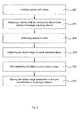
- Fig 8 illustrates a method for determining a difference between a sample position and an in-focus position.
- a first step 800 image data depicting a sample is captured.
- a feature set is extracted from the image data.
- a third step 804 the feature set is classified into a position difference value, wherein the position difference value corresponds to the difference.
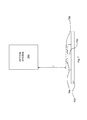
- Fig 9 illustrates a control device 900 configured to determine a difference between a sample position and an in-focus position.
- the control device 900 can comprise a reciever 902 arranged to receive image data from an image capturing device. The received image data is transferred to a processor 904, which in association with a memory 906, can be adapted to extract a feature set from the image data, and to classify the feature set into a position difference value, wherein said position difference value corresponds to the difference.
- the control device can comprise a transmitter 908 adpated to transfer the position difference value to, e.g. a steering motor system.
Landscapes
- Engineering & Computer Science (AREA)
- Physics & Mathematics (AREA)
- General Physics & Mathematics (AREA)
- Theoretical Computer Science (AREA)
- Computer Vision & Pattern Recognition (AREA)
- Multimedia (AREA)
- General Health & Medical Sciences (AREA)
- Molecular Biology (AREA)
- Biomedical Technology (AREA)
- Life Sciences & Earth Sciences (AREA)
- Health & Medical Sciences (AREA)
- Image Analysis (AREA)
- Microscoopes, Condenser (AREA)
- Automatic Focus Adjustment (AREA)
- Measurement Of Optical Distance (AREA)
- Investigating Materials By The Use Of Optical Means Adapted For Particular Applications (AREA)
- Image Processing (AREA)
Abstract
Description
- The present invention generally relates to a method for determining a difference between a sample position and an in-focus position, a vision inspection system and a control device.
- Computer-aided image analysis of biological material has become popular during the last years. For instance, computer-aided processes for counting and classifying white blood cells in a blood smear have been developed. These types of tests are e.g. an important step in the process of determining whether a patient suffers from an infection, allergy or blood cancer.
- In order to be able to make a reliable analysis it is of great importance that the image data is of proper quality, involving for instance that the image data is sharp, i.e. captured with accurate focus settings.
- Today, a common method for finding an in-focus position involves a first step of capturing several images at different positions, a second step of identifying high frequency components in the captured images and a third step of determining the image with the highest amount of high frequency components. The position corresponding to the image with the highest amount of high frequency components is thereafter chosen to be the in-focus position. In order to find the in-focus position it is not unlikely that as much as 20 images at different positions have to be captured.
- Moreover, if image data is to be captured for each of the objects to be classified, the image capturing process must be repeated a number of times, e.g. 20 times, for every object, which in turn implies that a large amount of image data has to be captured for every sample and that the vision inspection system must be readjusted a large number of times for every sample. Hence, this method consumes a lot of time and the large amount of readjustments may wear out the system.
- In view of the above, an objective of the invention is to solve or at least reduce the problems discussed above. In particular, an objective is to provide a method for determining a difference between a sample position and an in-focus position based upon image data. This implies that fewer images have to be captured in order to determine an in-focus position, and in many cases only one image is needed. By reducing the number of images the processing time will be reduced as well as the risk of wearing out the steering motor system.
- The above object is provided according to a first aspect by a method for determining a difference between a sample position and an in-focus position, said method comprising
capturing image data depicting a sample,
extracting a feature set from said captured image data, and
classifying, by using a machine learning algorithm that is trained to associate image data features to a position difference value, said feature set into said position difference value, wherein said position difference value corresponds to said difference. - Optionally, said feature set may comprise a sub-set of contrast features.
- Optionally, said sub-set of contrast features may be selected from a group consisting of a squared gradient function based upon said image data, a wavelet function based upon said image data and an auto-correlation function, such as Vollath's F4 function or a combination of Vollath's F4 function and Vollath's F5 function, based upon said image data, a variance for the whole image data and a Laplace-based focus measure.
- Optionally, said contrast features may be determined for a plurality of color layers.
- Optionally, said contrast features may be determined for a sub-set of said image data.
- Optionally, said feature set may comprise a sub-set of directional features.
- Optionally, a number of features of said sub-set of directional features may be determined by identifying differences between a plurality of color layers and determining at least one feature value based upon said determined differences.
- Optionally, a number of features of said sub-set of directional features may be determined by identifying a number of different objects having different heights in said sample, determining differences for said different objects, and determining at least one feature value based upon said determined differences for said different objects.
- Optionally, said sub-set of directional features may comprise a quotient between different Laplace-based focus measures according to the formula

- Optionally, said directional features may be determined for a sub-set of said image data.
- Optionally, said feature set may comprise a sub-set of content features.
- Optionally, said sub-set of content features may comprise overall content features and segmental content features.
- Optionally, said overall content features may be selected from a group consisting of mean intensity for the whole image data and variance for the whole image data.
- Optionally, said overall content features may be determined for a plurality of color layers.
- Optionally, the method may further comprise
determining foreground and background segments in said image data. - Optionally, the method may further comprise
segmenting said foreground segment into segments of object classes. - Optionally, the method may further comprise
determining a number of objects in at least one of said object classes. - Optionally, the method may further comprise
determining a number of pixels belonging to the objects of an object class for at least one of said object classes. - Optionally, said segmental content features may be selected from a group consisting of mean intensity for foreground segments, mean intensity for background segments, variance for foreground segments, variance for background segments and an area function expressing an area distribution between different segments.
- Optionally, said segmental content features may be selected from a group consisting of mean intensity for at least one of said object classes, variance for for at least one of said object classes and an area function expressing an area distribution between different object classes.
- Optionally, at least one of said object classes may be selected from a group consisting of a red blood cell (RBC) object class and a white blood cell (WBC) object class.
- Optionally, said foreground and background segments may be determined for a plurality of color layers.
- The area function may for instance be a function that expresses the relationship between foreground segments and background segments, such as a number of foreground segments pixels divided by a number of background segment pixels.
- The main purpose of the content features is to compensate for variations in the image that do not influence the degree/level of focus, but still influence the contrast features and directional features.
- Optionally, said step of classifying said feature set into a position difference value may be performed by a support vector machine.
- The above object is provided according to a second aspect by a vision inspection system comprising
a slide holder adapted to hold at least one slide comprising a sample,
an image capturing device configured to capture image data depicting said sample, wherein said image capturing device comprises an optical system and an image sensor,
a steering motor system configured to alter a distance between said sample and said optical system,
a processor connected to said image capturing device and said steering motor system, wherein said processor, in association with a memory, is configured to determine a difference between a sample position and an in-focus position by receiving said image data depicting said sample from said image capturing device, extracting a feature set from said image data, classifying, by using a machine learning algorithm that is trained to associate image data features to a position difference value, said feature set into said position difference value, wherein said position difference value corresponds to said difference and instructing said steering motor system to alter said distance between said sample and said optical system in accordance to said determined difference. - Optionally, said feature set may comprise a sub-set of contrast features.
- Optionally, said sub-set of contrast features may be selected from a group consisting of a squared gradient function based upon said image data, a wavelet function based upon said image data and an auto-correlation function, such as Vollath's F4 function or a combination of Vollath's F4 function and Vollath's F5 function, based upon said image data, a variance for the whole image data and a Laplace-based focus measure.
- Optionally, said feature set may comprise a sub-set of directional features.
- Optionally, a number of features of said sub-set of directional features may be determined by identifying differences between a plurality of color layers and determining at least one feature value based upon said determined differences.
- Optionally, said sub-set of directional features may comprise a quotient between different Laplace-based focus measures according to the formula

- Optionally, said feature set may comprise a sub-set of content features.
- Optionally, said features may be determined for a plurality of color layers.
- Optionally, said features may be determined for a sub-set of said image data.
- Optionally, said step of classifying said feature set into a position difference value may be performed by a support vector machine.
- The options of the first aspect are also applicable for this second aspect.
- The above object is provided according to a third aspect by a control device comprising
a receiver configured to receive image data depicting said sample,
a processor, in association with a memory, configured to determine a difference between a sample position and an in-focus position by extracting a feature set from said image data, classifying, by using a machine learning algorithm that is trained to associate image data features to a position difference value, said feature set into said position difference value, wherein said position difference value corresponds to said difference and
a transmitter configured to transmit said determined difference. - The options of the first aspect are also applicable to this third aspect.
- The above object is provided according to a fourth aspect by a computer program comprising software instructions arranged to be perform the method as described above when downloaded and run in an apparatus.
- Other objectives, features and advantages of the present invention will appear from the following detailed disclosure, from the attached dependent claims as well as from the drawings.
- Generally, all terms used in the claims are to be interpreted according to their ordinary meaning in the technical field, unless explicitly defined otherwise herein. All references to "a/an/the [element, device, component, means, step, etc]" are to be interpreted openly as referring to at least one instance of said element, device, component, means, step, etc., unless explicitly stated otherwise. The steps of any method disclosed herein do not have to be performed in the exact order disclosed, unless explicitly stated.
- The above, as well as additional objects, features and advantages of the present invention, will be better understood through the following illustrative and non-limiting detailed description of preferred embodiments of the present invention, with reference to the appended drawings, wherein:
-
Fig 1 diagrammatically illustrates a vision inspection system. -
Fig 2 illustrates a flowchart of a general method for inspecting samples using the vision inspection system. -
Fig 3 illustrates an example of a negatively defocused vision inspection system. -
Fig 4 illustrates an example of a positively defocused vision inspection system. -
Fig 5 illustrates another example of a positively defocused vision inspection system. -
Fig 6 illustrates a general overview of a method for determining a difference between a sample position and an in-focus position. -
Fig 7 illustrates an example of a situation where a large type of object in a sample is in an in-focus position at the same time as a small type of object in the sample is not in an in-focus position. -
Fig 8 illustrates a method for determining a difference between a sample position and an in-focus position. -
Fig 9 illustrates a control device adapted to determine a difference between a sample position and an in-focus position. -
Fig 1 generally illustrates avision inspection system 100. Aslide 102 comprising a sample, such as a blood sample, is placed in aslide holder 104. Theslide holder 104 may be adapted to hold a number of slides or only one, as illustrated infig 1 . Animage capturing device 106, comprising anoptical system 108 and animage sensor 110, is adapted to capture image data depicting the sample in theslide 102. Further, in order to control the light environment, and hence get image data which is easier to analyze, a light emitting device (not shown) may be used. - The image data captured by the
image capturing device 106 can be transferred to animage processing device 112. Theimage processing device 112 may be an external apparatus, such as a personal computer, connected to theimage capturing device 106. Alternatively, theimage processing device 112 may be incorporated in theimage capturing device 106. - The
image processing device 112 can comprise aprocessor 114, associated with amemory 116, configured to determine a difference between a sample position and an in-focus position. This process is further illustrated infig 8 . - When the difference is determined an instruction can be transferred to a
steering motor system 118. Thesteering motor system 118 can, based upon the instruction from theimage processing device 112, alter the distance z between theslide 102 and theoptical system 108. - A method for inspecting samples by using the vision inspection system is generally illustrated in
fig 2 . - In a
first step 200, the vision inspection system can be loaded with one or several slides. Each slide holds a sample. A sample may be, but is not restricted to, a biological specimen. - Next, in a
step 202, a first slide of the one or several slides is analyzed. This can be performed by moving the slide holder such that the first slide is in the field of view of the image capturing device. Alternatively, the image capturing device can be moved such that the first slide is in the field of view of the image capturing device. - In a
third step 204, a number of objects, such as white blood cells, to be analysed in further detail is recognized. In order to be able to perform an analysis in further detail the position of the objects can be stored. - In a
fourth step 206, object image data is captured for each detected object. In order to capture object image data for each detected object, the slide holder can be moved in accordance to the stored positions. Alternatively, instead of moving the slide holder, the image capturing device may be moved in accordance to the stored positions. - In a
fifth step 208, the object image data can be pre-classified into a pre-determined classification. For instance, if the objects are white blood cells, this step may comprise classifying the white blood cells into a specific type of white blood cells. - In a
sixth step 210, the object image data and associated pre-classications can be stored. Thus, it is possible for the operator of the vision inspection system to investigate image data depicting the objects for each sample together with associated pre-classifications. - If the vision inspection system is loaded with more than one slide, the
second step 202 to thesixth step 210 can be repeated for the other slides of the vision inspection system. - Moreover, in
step 204, a slide overall image may be captured. The magnification of the image capturing device, when capturing the slide overall image, may be 10X, i.e. ten times enlargement, and when capturing object image data the magnification of the image capturing device may be switched to 100X, i.e. hundreds times enlargement. The magnification may vary for different systems, but generally the magnification of the image capturing device is increased when switching from capturing the slide overall image to capturing the object image data. - In the above mentioned
step fig 2 , the optical system can be moved in order to capture image data depicting each of the detected objects in the sample. In order to improve the possibility of making a correct pre-classification of the object, the slide is to be placed in an in-focus position, which means that the distance z between the slide and the optical system is to be equal to, or at least close to, the focal distance f. If the distance z is greater than the focal distance f, the system may be said to be positively defocused, and vice versa, if the distance z is less than the focal distance f, the system may be said to be negatively defocused. - If the sample, for instance, is a blood sample, the sample may be smeared onto the slide. This may imply that the sample is not fully plain, which in turn implies that the difference between the distance z and the focal distance f is to be determined each time new object image data is to be captured.
- Moreover, the steering motor system may be slightly misaligned, which in turn implies that the difference between the distance z and the focal distance f is to be determined each time new object image data is to be captured.
- Further, other factors interfering with the vision inspection system, such as machine induced vibrations, may result in that the difference between the distance z and the focal distance f is preferable to be determined each time new object image data is to be captured.
-
Fig 3 illustates an example of a negatively defocused system. In this example, animage capturing device 300 is fixed and aslide holder 302a/302b, holding aslide 304a/304b comprising a sample, is adapted to be altered in a vertical direction. - In a first position, the
slide 304a, placed on theslide holder 302a, is positioned in a position zobj. In this position the system is negatively defocused, which means that the object image data will be perceived as blurry by the operator of the vision inspection system. - By analysing the image data captured in this first position, a difference Δz may be found. Then, by moving the slide holder in accordance to this determined difference Δz a new position zf will be reached. In this new position zf, the distance z between the optical system and the
slide 304b is equal, or close, to the focal distance f of the vision inspection system. Hence, the object image data captured in this position will be percieved as sharp by the operator. - In contrast to the vision inspection system illustrated in
fig 3 , the vision inspection system may be, as illustated infig 4 , positively defocused, i.e. the distance between an optical system of animage capturing device 400 and aslide 404 placed on aslide holder 402 is greater than the focal distance of the vision inspection system. - By capturing image data and determining a difference Δz based upon this captured image data, the vision inspection system may be changed in such a way that the distance z is equal, or close, to the focal distance f of the vision inspection system. This may e.g. be achieved by moving the image capturing device 400 a distance, corresponding to the determined difference Δz, closer to the
slide 404. - Another possiblity to change a positively defocused vision inspection system such that the distance z is equal, or close, to the focal distance f is illustrated in
fig 5 . - The vision inspection system comprises an
image capturing device 500 and aslide 504 placed on aslide holder 502. In order to compensate the vision inspection system in accordance to the determined difference Δz a combination of the methods illustrated infig 3 and fig 4 may be utilised. As illustratedfig 3 , theslide 504 and theslide holder 502 are moved towards theimage capturing device 500 and, as illustrated infig 4 , theimage capturing device 500 is moved towards theslide 504 and theslide holder 502. Theslide 504 and theslide holder 502 are moved a distance (1-α)Δz, where 0≤α≤1, towards theimage capturing device 500 and the image capturing device is moved a distance αΔz, where 0≤α≤1, towards theslide 502 and theslide holder 504. - In one embodiment of the vision inspection system the focal distance f is approximately 100µm and if the difference |z-f| is greater than 0.5µm the image data will be perceived as blurry, where z is the distance between the optical system and the sample and f is the focal distance. The above mentioned distances may vary in other embodiments.
- An overview of a method for determining a difference between a sample position and an in-focus position is illustrated in
fig 6 . In this overview,image data 600 is assumed to consist of background and foreground. The foreground may comprise red blood cells (RBC) and white blood cells (WBC). It will be appreciated by the skilled man in the art that the system may be changed such that other objects, instead of WBCs and RBCs, may be identified. -
Image data 600 captured by the image capturing device is transferred to asegmentation module 602 and to afeature extraction module 604. - The
segmentation module 602 identifies a number of different objects, in this case RBCs and WBCs. Thereafter, a mask for each of the identified objects can be generated and transferred to thefeature extraction module 604. In this particular case, a mask for WBC, a mask for RBC and a mask for background is generated and transferred to thefeature extraction module 604. - In some embodiments the nucelus of the WBC may be of particular interest. Hence, in these embodiments, a WBC nucelus mask may be used instead of, or in combination with, a WBC mask.
- Further, in some embodiments, the nucleus of the WBC may be esier to identify than the entire WBC. Therefore, in these embodiments, the WBC mask may be replaced by the WBC nucleus mask. Alternatively, in these embodiments, both the WBC mask and the WBC nucleus mask may be used.
- Moreover, in some embodiments, a part of the nucleus is of particular interest, or is easier to identify. In these embodiments a WBC nucleus part mask may be utilised.
- Based on the received
image data 600 and the masks transferred from thesegmentation module 602, thefeature extraction module 604 can extract three categories of features. - A first category is herein referred to as contrast features 606. In brief, this category can comprise a number of features which in different ways express the amount of high frequency components in the
image data 600. The content features 606 may e.g. comprise a wavelet function and a Vollath F4 function. Moreover, by utlizing one of the masks generated by thesegmentation module 602, features for a sub-set of the image data may be determined, e.g. by utlizing a WBC mask or a RBC mask, content features for WBC regions or RBC regions of the image data may be determined. - A second category is herein referred to as
directional features 608. This category can comprise, in brief, a number of features indicating whether the system is positively defocused or negatively defocused. - A third category is herein referred to as content features 610. In brief, this category can comprise a number of features that characterizes the
image data 600. The main purpose of the content features is to compensate for variations in the image that do not influence the degree/level of focus, but still influence the contrast features and directional features. - The features determined in the
feature extraction module 604 can be transferred to aclassification module 612. In this classification module, which e.g. may comprise a Support Vector Machine (SVM), a difference between the distance z and the focal distance f can be determined. The difference may e.g. be expressed in steps of 0.5µm, as illustrated infig 6 . - Alternatively, instead of using an SVM, another type of machine learning algorithm, such as an artifical neural network, a fuzzy logic algorithm or a k-nearest neighbour algorithm, may be used.
- The modules described above may be a software implemention, a hardware implementation, or a combination thereof, such as an ASIC ("Application Specific Integrated Circuit"). It will be appreciated by the skilled man in the art that the implementations of the modules may be different for different programming languages, different frameworks and different platforms.
- The contrast features may be seen as features which, in different ways, express the amount of high frequency components in the image.
- The contrast features 606 may comprise a number of functions, however, in order to make a reliable result it is desirable that they fulfill the following factors as good as possible:
- Accuracy
It is advantageous if the function is expressed in such a way that a distance between a current position and the in-focus position may be determined on the basis of the function, e.g. that a maximum (or minimum) of the function coincides with an image captured in the in-focus position. - Unimodality
It is advantageous if the function has only one global maximum (or minimum). - Speed
In order to be able to use the funtion in real-time applications, it is advantageous if the function is fast. - Different functions may coincide with different factors. Therefore, a number of functions can be chosen as contrast features. Some of these functions may coincide fairly good with all factors, while other functions may coincide very well with one of the factors and acceptable with the other factors. In order to make a good classification in the
classification module 612, it is advantageous if the sum of all contrast features fulfill the factors set forth above. It is therefore, in some embodiments, better to transfer too many contrast features than too few to theclassification module 612, since, if theclassification module 612 is configured accurately and trained with relevant training data, theclassification module 612 may be able to estimate the relevancy of the incoming contrast features. - Focus functions based on differentiations may be described as

where g(x,y) is the intensity level at (x,y), Θ is a threshold, and E(z)=z if z≥0, and E(z)=0 if z<0. These functions measure the the amount of high frequencies in the image by differentiating the image and adding the differentiated values together. - With the parameters set as Θ=0, m=2 and n=1 a squared gradient function is achieved. An advantage of this function is that no threshold value is needed. Another advantage is that by squaring the derivatives a sharper peak may be achieved, which implies that the maximum of the function may be easier to find.
- Focus functions based on the variance in the image data may be described as

whereg is the average intensity level in the image. - With m=2 the standard variance of the image data is achieved. This may be used as a contrast feature and/or a content feature.
- Moreover, a focus function called Vollath's F4, which is an autocorrelation function, may be included as a contrast feature. The Vollath's F4 may be described as

- Additionally, a combination of Vollath's F4 and Vollath's F5 may be included as a contrast feature. A combination may described as

- Further, a wavelet function may be used a contrast feature. An example of a wavelet function is achieved by sub-sampling the image data to a number of sub-sampled images, e.g. four sub-sampled images referred to as LL1, HL1, LH1 and HH1, wherein the HL1, LH1 and HH1 comprises the differences and LL1 comprises a compressed version of the image data, and in a next step, LL1 may be sub-sampled into double-sub-sampled images, e.g. the LL1 image is sub-sampled into four double-sub-sampled images referred to as LL2, HL2, LH2 and HH2, wherein the HL2, LH2 and HH2 comprises the differences and LL2 is a compressed version of LL1. Then, high frequency components are idenitfied in one of the sub-sampled images and a high frequency measure is determined, e.g. by identifying a number of pixels in the HL2 image with high intensity, removing pixels with very high intensity in order to reduce the impact of noise, adding together the remaining number of high intensity pixels into a high intensity measure and normalizing the high intensity measure by dividing the high intensity measure with the mean intensity of the LL2 image.
- The contrast features may further comprise a Laplace-based focus measure, i.e. a focus measure based on a convolution with a Laplace-like kernel. In one embodiment this focus measure may be implemented as a two dimensional convolution. In another embodiment this focus measure may be implemented as the square sum of two one dimensional convolutions, e.g. FX
n,c (R) + FYn,c (R), where

- Here Ic (x,y) is the intensity of color layer c evaluated at point (x,y), R is a subset of image points, and n≥0 is a parameter controlling the number of zeros in the Laplace-like kernel. It is also possible to use only one of FX
n,c (R) and FYn,c (R) as a contrast feature. - Further, the convolution may be limited to be made only for pixel values greater than a pre-determined threshold.
- Thanks to the RBC mask, the WBC mask and the background mask received from the
segmentation module 602, the contrast features described above may be also be determined for specific regions of the image data. If there are clear differences between different regions of the image data, this type of contrast feature may improve the result of theclassication module 612. - In order to determine whether the vision inspection system is positively or negatively defocused a sub-set of directional features may be determined.
- Since the objects comprised in the sample may differ in size, a large type of object, such as a WBC, may be focused, although a smaller type of object, such as a RBC, is not in focus. This phenomena is generally illustrated in
fig 7 , wherein aslide holder 700 holding aslide 702 comprising a sample, which, in turn, comprises a large type ofobject 704 and a small type ofobject 706. The distance between anoptical system 708 of a vision inspection system (not illustrated) and the large type ofobject 704 may be equal, or close, to a focal distance f, at the same time as the distance between the small type ofobject 706 and theoptical system 708 is not equal, or close, to the focal distance f. This implies that a standard deviation of the pixel intensities of the regions of the image data comprising large type of objects may be higher than the regions of the image data comprising small type of objects. Hence, differences in standard deviations for different regions of the image data may be used as directional features. - Further, since different colors have different wavelenghts, the different color layers may have different focal distances. By determining the standard deviation for each color layer, a difference may be detected, and based on this difference an indication of whether the system is positively or negatively defocused may be achieved. Therefore, standard deviation differences for different color layers may be used as directional features. The standard deviation differences in different color layers may be determined for the whole image data or for specific regions of the image data, such as regions of the image data comprising large type objects and/or regions comprising small type objects.
- The standard deviation may be described as

where Ic (x,y) is the intensity of the color layer c evaluated at point (x,y), R is a sub-set of image points, and Îc (R) is the mean intensity of color layer c over the image points in R. - Another directional feature may be determined by forming quotients between different Laplace-like convolutions, varying the number of zeros of the kernel and using several layers:
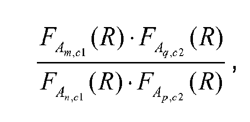
where A denotes X or Y, i.e. FA is one of the functions FX and FY used in the definition of the Laplace-based focus measure, m>n, p>q, c1 and c2 denote two different color layers, and R is a sub-set of image points. R may correspond to a mask from the segmentation module. - An example of a directional feature according to the description above may be

where g denotes the green color layer, b denotes the blue color layer, and R is the intersection of every second column and every fourth row of R. - The content features may be seen as features that, in different ways, express the content of the image data. For instance, if a great number of blood cells are present the amount of high frequency components will be higher than in a situation where a small number of blood cells are present. The main purpose of the content features is to compensate for variations in the image that do not influence the degree/level of focus, but still influence the contrast features and directional features.
- The content features may comprise a mean intensity for the whole image data, mean intensity for the background, mean intensity for the RBCs, mean intensity for the WBCs, image standard deviation for the whole image data, image standard deviation for the RBCs, image standard deviation for the WBCs, number of pixels occupied by RBCs, number of pixels occupied by WBCs, number of RBCs and/or the number of WBCs.
- Contrast features, directional features and/or content features may be determined for a sub-set of the image data by utilizing the masks generated by the segmentation module.
- Further, contrast features, directional features and/or content features may be determined for one specific color layer or a combination of several color layers.
- Moreover, contrast features, directional features and/or content features may be determined for a sub-set of the image data for one specific color layer or a combination of several color layers.
-
Fig 8 illustrates a method for determining a difference between a sample position and an in-focus position. - In a
first step 800, image data depicting a sample is captured. - In a
second step 802, a feature set is extracted from the image data. - In a
third step 804, the feature set is classified into a position difference value, wherein the position difference value corresponds to the difference. -
Fig 9 illustrates acontrol device 900 configured to determine a difference between a sample position and an in-focus position. Thecontrol device 900 can comprise areciever 902 arranged to receive image data from an image capturing device. The received image data is transferred to aprocessor 904, which in association with amemory 906, can be adapted to extract a feature set from the image data, and to classify the feature set into a position difference value, wherein said position difference value corresponds to the difference. Further, the control device can comprise atransmitter 908 adpated to transfer the position difference value to, e.g. a steering motor system. - The invention has mainly been described above with reference to a few embodiments. However, as is readily appreciated by a person skilled in the art, other embodiments than the ones disclosed above are equally possible within the scope of the invention, as defined by the appended patent claims.
- Embodiments of the invention is described with the following examples.
- 1. A method for determining a difference between a sample position and an in-focus position, said method comprising
capturing image data depicting a sample,
extracting a feature set from said captured image data, and
classifying, by using a machine learning algorithm that is trained to associate image data features to a position difference value, said feature set into said position difference value, wherein said position difference value corresponds to said difference. - 2. The method according to example 1, wherein said feature set comprises a sub-set of contrast features.
- 3. The method according to example 2, wherein said sub-set of contrast features are selected from a group consisting of a squared gradient function based upon said image data, a wavelet function based upon said image data, an auto-correlation function, such as Vollath's F4 function or a combination of Vollath's F4 function and Vollath's F5 function, based upon said image, a variance for the whole image data and a Laplace-based focus measure.
- 4. The method according to any of examples 2 or 3, wherein said contrast features are determined for a plurality of color layers.
- 5. The method according to any of examples 2 to 4, wherein said contrast features are determined for a sub-set of said image data.
- 6. The method according to any of the preceding examples, wherein said feature set comprises a sub-set of directional features.
- 7. The method according to example 6, wherein a number of features of said sub-set of directional features are determined by identifying differences between a plurality of color layers and determining at least one feature value based upon said determined differences.
- 8. The method according to any of the examples 6 or 7, wherein a number of features of said sub-set of directional features are determined by identifying a number of different objects having different heights in said sample, determining differences for said different objects, and determining at least one feature value based upon said determined differences for said different objects.
- 9. The method according to any of the examples 6 to 8, wherein said sub-set of directional features comprises a quotient between different Laplace-based focus measures according to the formula

- 10. The method according to any of the examples 6 to 9, wherein said directional features are determined for a sub-set of said image data.
- 11. The method according to any of the preceding examples, wherein said feature set comprises a sub-set of content features.
- 12. The method according to example 11, wherein said sub-set of content features comprises overall content features and segmental content features.
- 13. The method according to example 12, wherein said overall content features are selected from a group consisting of mean intensity for the whole image data and variance for the whole image data.
- 14. The method according to any of the examples 12 or 13, wherein said overall content features are determined for a plurality of color layers.
- 15. The method according to any of the preceding examples, further comprising
determining foreground and background segments in said image data. - 16. The method according to example 15, further comprising
segmenting said foreground segment into segments of object classes. - 17. The method according to example 16, further comprising
determining a number of objects in at least one of said object classes. - 18. The method according to any of the examples 16 or 17, further comprising
determining a number of pixels belonging to the objects of an object class for at least one of said object classes. - 19. The method according to any of the examples 15 to 18, wherein said segmental content features are selected from a group consisting of mean intensity for foreground segments, mean intensity for background segments, variance for foreground segments, variance for background segments and an area function expressing an area distribution between different segments.
- 20. The method according to any of the examples 16 to 18, wherein said segmental content features are selected from a group consisting of mean intensity for at least one of said object classes, variance for for at least one of said object classes and an area function expressing an area distribution between different object classes.
- 21. The method according to any of the examples 16 to 20, wherein at least one of said object classes is selected from a group consisting of a red blood cell (RBC) object class and a white blood cell (WBC) object class.
- 22. The method according to any of the examples 15 to 21, wherein said foreground and background segments are determined for a plurality of color layers.
- 23. The method according to any of the preceding examples, wherein said step of classifying said feature set into a position difference value is performed by a support vector machine.
- 24. A vision inspection system comprising
a slide holder adapted to hold at least one slide comprising a sample,
an image capturing device configured to capture image data depicting said sample, wherein said image capturing device comprises an optical system and an image sensor,
a steering motor system configured to alter a distance between said sample and said optical system,
a processor connected to said image capturing device and said steering motor system, wherein said processor, in association with a memory, is configured to determine a difference between a sample position and an in-focus position by receiving said image data depicting said sample from said image capturing device, extracting a feature set from said image data, classifying, by using a machine learning algorithm that is trained to associate image data features to a position difference value, said feature set into said position difference value, wherein said position difference value corresponds to said difference and instructing said steering motor system to alter said distance between said sample and said optical system in accordance to said determined difference. - 25. The vision inspection system according to example 24, wherein said feature set comprises a sub-set of contrast features.
- 26. The vision inspection system according to example 25, wherein said sub-set of contrast features are selected from a group consisting of a squared gradient function based upon said image data, a wavelet function based upon said image data and an auto-correlation function, such as Vollath's F4 function or a combination of Vollath's F4 function and Vollath's F5 function, based upon said image, a variance for the whole image data and a Laplace-based focus measure.
- 27. The vision inspection system according to any of the examples 24 to 26, wherein said feature set comprises a sub-set of directional features.
- 28. The vision inspection system according to example 27, wherein a number of features of said sub-set of directional features are determined by identifying differences between a plurality of color layers and determining at least one feature value based upon said determined differences.
- 29. The vision inspection system according to any of the examples 27 or 28, wherein said sub-set of directional features comprises a quotient between different Laplace-based focus measures according to the formula

- 30. The vision inspection system according to any of the examples 24 to 29, wherein said feature set comprises a sub-set of content features.
- 31. The vision inspection system according to any of examples 24 to 30, wherein said features are determined for a plurality of color layers.
- 32. The vision inspection system according to any of examples 24 to 31, wherein said features are determined for a sub-set of said image data.
- 33. The vision inspection system according to any of the examples 24 to 32, wherein said step of classifying said feature set into a position difference value is performed by a support vector machine.
- 34. A control device comprising
a receiver configured to receive image data depicting said sample,
a processor, in association with a memory, configured to determine a difference between a sample position and an in-focus position by extracting a feature set from said image data, classifying, by using a machine learning algorithm that is trained to associate image data features to a position difference value, said feature set into said position difference value, wherein said position difference value corresponds to said difference and
a transmitter configured to transmit said determined difference. - 35. A computer program comprising software instructions arranged to be perform the method according to any of the examples 1 to 23 when downloaded and run in an apparatus.
Claims (14)
- A method for determining a difference (ΔZ) between a sample position and an in-focus position relative to an optical system based on a single image, said method comprising
capturing (800) image data depicting said sample when being in said sample position,
extracting (802), from said image data, a set of features comprising a plurality of contrast features, the plurality of contrast features being generated using at least two of:a squared gradient function based upon said image data,a wavelet function based upon said image data,an auto-correlation function, such as Vollath's F4 function or a combination of Vollath's F4 function and Vollath's F5 function, based upon said image data,a variance for the whole image data, anda Laplace-based focus measure, and
classifying (804), by using a machine learning algorithm that has been trained to associate sets of features extracted from images with predetermined position difference values, said set of features into a corresponding position difference value, wherein said corresponding position difference value corresponds to said difference (ΔZ) between the sample position and the in-focus position. - The method according to claim 1, wherein the difference is positive or negative.
- The method according to any of the preceding claims, wherein said plurality of contrast features are determined for a plurality of color layers.
- The method according to any of the preceding claims, wherein at least one of said contrast features are determined for a sub-set of said image data.
- The method according to any of the preceding claims, wherein said set of features comprises a set of directional features indicating whether the system is positively defocused or negatively defocused.
- The method according to claim 5, wherein at least said directional features are determined for a single color layer.
- The method according to any of the claims 5 or 6, wherein a number of features of said sub-set of directional features are determined by identifying a number of different objects having different heights in said sample, determining differences for said different objects, and determining at least one feature value based upon said determined differences for said different objects.
- The method according to any of the claims 5 to 7, wherein said directional features are determined for a sub-set of said image data.
- The method according to any of the preceding claims, wherein said step of classifying said feature set into a position difference value is performed by a support vector machine.
- An image processing device (112) comprising
a processor (114), in association with a memory (116), being configured to determine a difference (ΔZ) between a sample position and an in-focus position relative to an optical system based on a single image, said processor being arranged to
capture image data depicting a sample when being in said sample position,
extract, from said image data, a set of features comprising a plurality of contrast features, the plurality of contrast features being generated using at least two of:a squared gradient function based upon said image data,a wavelet function based upon said image data,an auto-correlation function, such as Vollath's F4 function or a combination of Vollath's F4 function and Vollath's F5 function, based upon said image data,a variance for the whole image data, anda Laplace-based focus measure, andclassify, by using a machine learning algorithm that has been trained to associate sets of features extracted from images with predetermined position difference values, said set of features into a corresponding position difference value, wherein said corresponding position difference value corresponds to said difference (ΔZ) between the sample position and the in-focus position. - The image processing device according to claim 10, wherein said contrast features are determined for a plurality of color layers.
- The image processing device according to any of the claims 10-11, wherein said set of features comprises a set of directional features.
- A vision inspection system (100) comprising
a slide holder (104) adapted to hold at least one slide comprising a sample,
an image capturing device (106) configured to capture image data depicting said sample, wherein said image capturing device comprises an optical system (108) and an image sensor (110),
a steering motor system (118) configured to alter a distance (z) between said sample and said optical system, wherein said image capturing device (106) further comprises an image processing device (112) according to any of claims 10-12,
wherein said image processing device (112) is configured to receive said image data depicting said sample from said image capturing device, and
wherein said image processing device (112) is configured to transmit an instruction to said steering motor system to alter said distance (z) between said sample and said optical system in accordance to a distance which is determined by said image processing device (112). - A computer program comprising software instructions arranged to perform the method according to any of the claims 1 to 9 when downloaded and run in an apparatus.
Priority Applications (1)
| Application Number | Priority Date | Filing Date | Title |
|---|---|---|---|
| EP14171189.5A EP2775349B1 (en) | 2007-03-08 | 2007-03-08 | A method for determining an in-focus position and a vision inspection system |
Applications Claiming Priority (2)
| Application Number | Priority Date | Filing Date | Title |
|---|---|---|---|
| EP14171189.5A EP2775349B1 (en) | 2007-03-08 | 2007-03-08 | A method for determining an in-focus position and a vision inspection system |
| EP07103773.3A EP1986046B1 (en) | 2007-03-08 | 2007-03-08 | A method for determining an in-focus position and a vision inspection system |
Related Parent Applications (2)
| Application Number | Title | Priority Date | Filing Date |
|---|---|---|---|
| EP07103773.3A Division EP1986046B1 (en) | 2007-03-08 | 2007-03-08 | A method for determining an in-focus position and a vision inspection system |
| EP07103773.3A Division-Into EP1986046B1 (en) | 2007-03-08 | 2007-03-08 | A method for determining an in-focus position and a vision inspection system |
Publications (2)
| Publication Number | Publication Date |
|---|---|
| EP2775349A1 true EP2775349A1 (en) | 2014-09-10 |
| EP2775349B1 EP2775349B1 (en) | 2021-08-11 |
Family
ID=38229194
Family Applications (2)
| Application Number | Title | Priority Date | Filing Date |
|---|---|---|---|
| EP07103773.3A Active EP1986046B1 (en) | 2007-03-08 | 2007-03-08 | A method for determining an in-focus position and a vision inspection system |
| EP14171189.5A Active EP2775349B1 (en) | 2007-03-08 | 2007-03-08 | A method for determining an in-focus position and a vision inspection system |
Family Applications Before (1)
| Application Number | Title | Priority Date | Filing Date |
|---|---|---|---|
| EP07103773.3A Active EP1986046B1 (en) | 2007-03-08 | 2007-03-08 | A method for determining an in-focus position and a vision inspection system |
Country Status (4)
| Country | Link |
|---|---|
| US (1) | US10210376B2 (en) |
| EP (2) | EP1986046B1 (en) |
| JP (2) | JP5198476B2 (en) |
| WO (1) | WO2008107303A1 (en) |
Cited By (1)
| Publication number | Priority date | Publication date | Assignee | Title |
|---|---|---|---|---|
| DE102020124006B3 (en) | 2020-09-15 | 2022-01-05 | Laser Imaging Systems Gmbh | EXPOSURE CONTROL IN PHOTOLITHOGRAPHIC DIRECT EXPOSURE METHODS FOR CREATING CIRCUIT BOARDS OR CIRCUITS |
Families Citing this family (20)
| Publication number | Priority date | Publication date | Assignee | Title |
|---|---|---|---|---|
| US9041791B2 (en) | 2011-02-01 | 2015-05-26 | Roche Diagnostics Hematology, Inc. | Fast auto-focus in imaging |
| KR102095617B1 (en) | 2013-03-15 | 2020-03-31 | 아이리스 인터내셔널 인크. | Autofocus systems and methods for particle analysis in blood samples |
| US10831013B2 (en) | 2013-08-26 | 2020-11-10 | S.D. Sight Diagnostics Ltd. | Digital microscopy systems, methods and computer program products |
| US10482595B2 (en) * | 2014-08-27 | 2019-11-19 | S.D. Sight Diagnostics Ltd. | System and method for calculating focus variation for a digital microscope |
| JP6844564B2 (en) * | 2018-03-14 | 2021-03-17 | オムロン株式会社 | Inspection system, identification system, and learning data generator |
| CN109507792B (en) * | 2018-12-27 | 2021-07-06 | 湖南品信生物工程有限公司 | Optical microscope automatic focusing method based on machine learning |
| CN109561257B (en) * | 2019-01-18 | 2020-09-18 | 深圳看到科技有限公司 | Picture focusing method, device, terminal and corresponding storage medium |
| US20210049345A1 (en) * | 2019-08-15 | 2021-02-18 | Advanced Solutions Life Sciences, Llc | Systems and methods for automating biological structure identification utilizing machine learning |
| BR112022011312A2 (en) | 2019-12-12 | 2022-08-23 | S D Sight Diagnostics Ltd | ANALYSIS OF AN ANALYTE DISPOSED IN A MEDIUM |
| WO2021150973A1 (en) * | 2020-01-24 | 2021-07-29 | Duke University | Intelligent automated imaging system |
| JP7494490B2 (en) | 2020-03-05 | 2024-06-04 | ソニーグループ株式会社 | Signal Acquisition Device, Signal Acquisition System, and Signal Acquisition Method |
| CN111832571B (en) * | 2020-07-09 | 2021-03-05 | 哈尔滨市科佳通用机电股份有限公司 | Automatic detection method for truck brake beam strut fault |
| WO2023002678A1 (en) | 2021-07-19 | 2023-01-26 | 浜松ホトニクス株式会社 | Feature output model generation system, feature output model generation method, feature output model generation program, and feature output model |
| EP4336238A4 (en) * | 2021-07-19 | 2025-05-14 | Hamamatsu Photonics K.K. | Focus position estimation system, focus position estimation method, focus position estimation program, semiconductor inspection system, and biological observation system |
| CN117677988A (en) * | 2021-07-19 | 2024-03-08 | 浜松光子学株式会社 | Feature quantity output model generation system, feature quantity output model generation method, feature quantity output model generation program and feature quantity output model |
| CN114760415B (en) * | 2022-04-18 | 2024-02-02 | 上海千映智能科技有限公司 | Lens focusing method, system, equipment and medium |
| JP2024104391A (en) | 2023-01-24 | 2024-08-05 | 浜松ホトニクス株式会社 | Focus position estimation method, focus position estimation program, focus position estimation system, model generation method, model generation program, model generation system, and focus position estimation model |
| EP4439147A1 (en) * | 2023-03-28 | 2024-10-02 | Leica Microsystems CMS GmbH | Computer-implemented methods for manual focus adjustment of a microscope and microscopes with manual focus adjustment |
| CN117132646B (en) * | 2023-10-26 | 2024-01-05 | 湖南自兴智慧医疗科技有限公司 | Split-phase automatic focusing system based on deep learning |
| WO2026074778A1 (en) * | 2024-10-02 | 2026-04-09 | パナソニックIpマネジメント株式会社 | Focal position deviation amount correction method, focal position deviation amount correction system, and program |
Citations (3)
| Publication number | Priority date | Publication date | Assignee | Title |
|---|---|---|---|---|
| JP2000338385A (en) * | 1999-05-28 | 2000-12-08 | Ricoh Co Ltd | Automatic focusing device and focusing method thereof |
| US7034883B1 (en) * | 1999-08-10 | 2006-04-25 | Cellavision Ab | Automatic focusing |
| US20060204121A1 (en) * | 2005-03-03 | 2006-09-14 | Bryll Robert K | System and method for single image focus assessment |
Family Cites Families (22)
| Publication number | Priority date | Publication date | Assignee | Title |
|---|---|---|---|---|
| JPS63167268A (en) * | 1986-12-27 | 1988-07-11 | Hitachi Ltd | Blood image automatic classification device |
| JP2918663B2 (en) | 1990-09-06 | 1999-07-12 | 株式会社日立製作所 | Display device in microscope visual field and microscope image processing device including the same |
| US5790710A (en) * | 1991-07-12 | 1998-08-04 | Jeffrey H. Price | Autofocus system for scanning microscopy |
| US5548661A (en) * | 1991-07-12 | 1996-08-20 | Price; Jeffrey H. | Operator independent image cytometer |
| JPH07107363A (en) | 1993-10-07 | 1995-04-21 | Brother Ind Ltd | Auto focus method |
| US5544256A (en) * | 1993-10-22 | 1996-08-06 | International Business Machines Corporation | Automated defect classification system |
| JPH0887600A (en) * | 1994-09-19 | 1996-04-02 | Topcon Corp | Feature extraction device |
| AU3490695A (en) * | 1994-09-20 | 1996-04-09 | Neopath, Inc. | Cytological slide scoring apparatus |
| ATE475260T1 (en) * | 1998-11-25 | 2010-08-15 | Iridian Technologies Inc | RAPID FOCUS ASSESSMENT SYSTEM AND METHOD FOR IMAGE CAPTURE |
| US6753919B1 (en) | 1998-11-25 | 2004-06-22 | Iridian Technologies, Inc. | Fast focus assessment system and method for imaging |
| US6564194B1 (en) * | 1999-09-10 | 2003-05-13 | John R. Koza | Method and apparatus for automatic synthesis controllers |
| DE60130671D1 (en) | 2001-12-24 | 2007-11-08 | St Microelectronics Srl | Method for contrast enhancement in digital color images |
| JP3812824B2 (en) * | 2002-03-12 | 2006-08-23 | カシオ計算機株式会社 | Imaging apparatus, focusing status display method, and program |
| DE10217404A1 (en) * | 2002-04-18 | 2003-11-06 | Leica Microsystems | Autofocus method for a microscope and system for adjusting the focus for a microscope |
| JP2004070139A (en) | 2002-08-08 | 2004-03-04 | Matsushita Electric Ind Co Ltd | Microscope image capturing apparatus and microscope image capturing method |
| US7505544B2 (en) * | 2003-01-10 | 2009-03-17 | Faj International Holdings, Llc | Method and apparatus for detecting and classifying explosives and controlled substances |
| US7307783B2 (en) | 2003-02-21 | 2007-12-11 | Kla-Tencor Technologies Corporation | Catadioptric imaging system employing immersion liquid for use in broad band microscopy |
| JP4345622B2 (en) * | 2003-11-05 | 2009-10-14 | オムロン株式会社 | Eye color estimation device |
| JP3903048B2 (en) | 2004-04-26 | 2007-04-11 | キヤノン株式会社 | Image extraction method |
| JP4376145B2 (en) | 2004-07-22 | 2009-12-02 | 日立ソフトウエアエンジニアリング株式会社 | Image classification learning processing system and image identification processing system |
| DE102005024063B3 (en) * | 2005-05-25 | 2006-07-06 | Soft Imaging System Gmbh | Method for optical scanning sample involves recording of individual image whereby in each case, it is evaluated by means of adaptive sensor unit with respect to contrast totally or partly |
| US7417213B2 (en) * | 2005-06-22 | 2008-08-26 | Tripath Imaging, Inc. | Apparatus and method for rapid microscopic image focusing having a movable objective |
-
2007
- 2007-03-08 EP EP07103773.3A patent/EP1986046B1/en active Active
- 2007-03-08 EP EP14171189.5A patent/EP2775349B1/en active Active
-
2008
- 2008-02-19 JP JP2009552156A patent/JP5198476B2/en active Active
- 2008-02-19 US US12/449,873 patent/US10210376B2/en active Active - Reinstated
- 2008-02-19 WO PCT/EP2008/051993 patent/WO2008107303A1/en not_active Ceased
-
2012
- 2012-07-30 JP JP2012168747A patent/JP5461630B2/en active Active
Patent Citations (3)
| Publication number | Priority date | Publication date | Assignee | Title |
|---|---|---|---|---|
| JP2000338385A (en) * | 1999-05-28 | 2000-12-08 | Ricoh Co Ltd | Automatic focusing device and focusing method thereof |
| US7034883B1 (en) * | 1999-08-10 | 2006-04-25 | Cellavision Ab | Automatic focusing |
| US20060204121A1 (en) * | 2005-03-03 | 2006-09-14 | Bryll Robert K | System and method for single image focus assessment |
Cited By (3)
| Publication number | Priority date | Publication date | Assignee | Title |
|---|---|---|---|---|
| DE102020124006B3 (en) | 2020-09-15 | 2022-01-05 | Laser Imaging Systems Gmbh | EXPOSURE CONTROL IN PHOTOLITHOGRAPHIC DIRECT EXPOSURE METHODS FOR CREATING CIRCUIT BOARDS OR CIRCUITS |
| WO2022057981A1 (en) | 2020-09-15 | 2022-03-24 | Laser Imaging Systems Gmbh | Exposure control in photolithographic direct exposure methods for manufacturing circuit boards or circuits |
| US12169370B2 (en) | 2020-09-15 | 2024-12-17 | Laser Imaging Systems Gmbh | Exposure control in photolithographic direct exposure methods for manufacturing circuit boards or circuits |
Also Published As
| Publication number | Publication date |
|---|---|
| JP2010525374A (en) | 2010-07-22 |
| EP1986046A1 (en) | 2008-10-29 |
| US20100177187A1 (en) | 2010-07-15 |
| US10210376B2 (en) | 2019-02-19 |
| JP2013050713A (en) | 2013-03-14 |
| WO2008107303A1 (en) | 2008-09-12 |
| JP5198476B2 (en) | 2013-05-15 |
| JP5461630B2 (en) | 2014-04-02 |
| EP1986046B1 (en) | 2014-07-16 |
| EP2775349B1 (en) | 2021-08-11 |
Similar Documents
| Publication | Publication Date | Title |
|---|---|---|
| EP1986046B1 (en) | A method for determining an in-focus position and a vision inspection system | |
| EP2889619B1 (en) | Image processing device, image processing method, computer-readable medium, and image processing system | |
| US9684958B2 (en) | Image processing device, program, image processing method, computer-readable medium, and image processing system | |
| CN104487564B (en) | Image processing device, image processing method, and image processing system | |
| US11226280B2 (en) | Automated slide assessments and tracking in digital microscopy | |
| US5933519A (en) | Cytological slide scoring apparatus | |
| CN107909010B (en) | Road obstacle detection method and device | |
| Chen et al. | Deep learning based automatic immune cell detection for immunohistochemistry images | |
| US20220012884A1 (en) | Image analysis system and analysis method | |
| WO1996009594A1 (en) | Apparatus for automated identification of thick cell groupings on a biological specimen | |
| CN114332058B (en) | Methods, devices, equipment, and media for serum quality identification based on neural networks | |
| WO2014087689A1 (en) | Image processing device, image processing system, and program | |
| US8467590B2 (en) | Microscopy analysis technique | |
| EP1947441B1 (en) | Apparatus for determining positions of objects contained in a sample | |
| US8571279B2 (en) | Spot quantification apparatus, spot quantification method, and recording medium | |
| JP2023501939A (en) | Apparatus and method for identifying tube assembly type | |
| JPH10302069A (en) | Object identification device | |
| Walkowski et al. | Histopathologic patterns of nervous system tumors based on computer vision methods and whole slide imaging (WSI) |
Legal Events
| Date | Code | Title | Description |
|---|---|---|---|
| PUAI | Public reference made under article 153(3) epc to a published international application that has entered the european phase |
Free format text: ORIGINAL CODE: 0009012 |
|
| 17P | Request for examination filed |
Effective date: 20140604 |
|
| AC | Divisional application: reference to earlier application |
Ref document number: 1986046 Country of ref document: EP Kind code of ref document: P |
|
| AK | Designated contracting states |
Kind code of ref document: A1 Designated state(s): AT BE BG CH CY CZ DE DK EE ES FI FR GB GR HU IE IS IT LI LT LU LV MC MT NL PL PT RO SE SI SK TR |
|
| R17P | Request for examination filed (corrected) |
Effective date: 20150310 |
|
| RBV | Designated contracting states (corrected) |
Designated state(s): AT BE BG CH CY CZ DE DK EE ES FI FR GB GR HU IE IS IT LI LT LU LV MC MT NL PL PT RO SE SI SK TR |
|
| STAA | Information on the status of an ep patent application or granted ep patent |
Free format text: STATUS: EXAMINATION IS IN PROGRESS |
|
| 17Q | First examination report despatched |
Effective date: 20190604 |
|
| REG | Reference to a national code |
Ref country code: DE Ref legal event code: R079 Ref document number: 602007061264 Country of ref document: DE Free format text: PREVIOUS MAIN CLASS: G03B0013320000 Ipc: G06K0009000000 |
|
| RIC1 | Information provided on ipc code assigned before grant |
Ipc: G06T 7/11 20170101ALI20201223BHEP Ipc: G03B 13/32 20060101ALI20201223BHEP Ipc: G06K 9/00 20060101AFI20201223BHEP Ipc: G06T 7/90 20170101ALI20201223BHEP |
|
| GRAP | Despatch of communication of intention to grant a patent |
Free format text: ORIGINAL CODE: EPIDOSNIGR1 |
|
| STAA | Information on the status of an ep patent application or granted ep patent |
Free format text: STATUS: GRANT OF PATENT IS INTENDED |
|
| INTG | Intention to grant announced |
Effective date: 20210315 |
|
| RIN1 | Information on inventor provided before grant (corrected) |
Inventor name: ALMERS, MARTIN Inventor name: BEIJBOM, OSCAR Inventor name: HEDLUND, SVEN |
|
| GRAS | Grant fee paid |
Free format text: ORIGINAL CODE: EPIDOSNIGR3 |
|
| GRAA | (expected) grant |
Free format text: ORIGINAL CODE: 0009210 |
|
| STAA | Information on the status of an ep patent application or granted ep patent |
Free format text: STATUS: THE PATENT HAS BEEN GRANTED |
|
| AC | Divisional application: reference to earlier application |
Ref document number: 1986046 Country of ref document: EP Kind code of ref document: P |
|
| AK | Designated contracting states |
Kind code of ref document: B1 Designated state(s): AT BE BG CH CY CZ DE DK EE ES FI FR GB GR HU IE IS IT LI LT LU LV MC MT NL PL PT RO SE SI SK TR |
|
| REG | Reference to a national code |
Ref country code: GB Ref legal event code: FG4D |
|
| REG | Reference to a national code |
Ref country code: CH Ref legal event code: EP |
|
| REG | Reference to a national code |
Ref country code: DE Ref legal event code: R096 Ref document number: 602007061264 Country of ref document: DE |
|
| REG | Reference to a national code |
Ref country code: IE Ref legal event code: FG4D Ref country code: AT Ref legal event code: REF Ref document number: 1420138 Country of ref document: AT Kind code of ref document: T Effective date: 20210915 |
|
| REG | Reference to a national code |
Ref country code: DE Ref legal event code: R079 Ref document number: 602007061264 Country of ref document: DE Free format text: PREVIOUS MAIN CLASS: G06K0009000000 Ipc: G06V0010000000 |
|
| REG | Reference to a national code |
Ref country code: LT Ref legal event code: MG9D |
|
| REG | Reference to a national code |
Ref country code: NL Ref legal event code: MP Effective date: 20210811 |
|
| REG | Reference to a national code |
Ref country code: AT Ref legal event code: MK05 Ref document number: 1420138 Country of ref document: AT Kind code of ref document: T Effective date: 20210811 |
|
| PG25 | Lapsed in a contracting state [announced via postgrant information from national office to epo] |
Ref country code: SE Free format text: LAPSE BECAUSE OF FAILURE TO SUBMIT A TRANSLATION OF THE DESCRIPTION OR TO PAY THE FEE WITHIN THE PRESCRIBED TIME-LIMIT Effective date: 20210811 Ref country code: PT Free format text: LAPSE BECAUSE OF FAILURE TO SUBMIT A TRANSLATION OF THE DESCRIPTION OR TO PAY THE FEE WITHIN THE PRESCRIBED TIME-LIMIT Effective date: 20211213 Ref country code: ES Free format text: LAPSE BECAUSE OF FAILURE TO SUBMIT A TRANSLATION OF THE DESCRIPTION OR TO PAY THE FEE WITHIN THE PRESCRIBED TIME-LIMIT Effective date: 20210811 Ref country code: FI Free format text: LAPSE BECAUSE OF FAILURE TO SUBMIT A TRANSLATION OF THE DESCRIPTION OR TO PAY THE FEE WITHIN THE PRESCRIBED TIME-LIMIT Effective date: 20210811 Ref country code: LT Free format text: LAPSE BECAUSE OF FAILURE TO SUBMIT A TRANSLATION OF THE DESCRIPTION OR TO PAY THE FEE WITHIN THE PRESCRIBED TIME-LIMIT Effective date: 20210811 Ref country code: AT Free format text: LAPSE BECAUSE OF FAILURE TO SUBMIT A TRANSLATION OF THE DESCRIPTION OR TO PAY THE FEE WITHIN THE PRESCRIBED TIME-LIMIT Effective date: 20210811 Ref country code: BG Free format text: LAPSE BECAUSE OF FAILURE TO SUBMIT A TRANSLATION OF THE DESCRIPTION OR TO PAY THE FEE WITHIN THE PRESCRIBED TIME-LIMIT Effective date: 20211111 |
|
| PG25 | Lapsed in a contracting state [announced via postgrant information from national office to epo] |
Ref country code: PL Free format text: LAPSE BECAUSE OF FAILURE TO SUBMIT A TRANSLATION OF THE DESCRIPTION OR TO PAY THE FEE WITHIN THE PRESCRIBED TIME-LIMIT Effective date: 20210811 Ref country code: LV Free format text: LAPSE BECAUSE OF FAILURE TO SUBMIT A TRANSLATION OF THE DESCRIPTION OR TO PAY THE FEE WITHIN THE PRESCRIBED TIME-LIMIT Effective date: 20210811 Ref country code: GR Free format text: LAPSE BECAUSE OF FAILURE TO SUBMIT A TRANSLATION OF THE DESCRIPTION OR TO PAY THE FEE WITHIN THE PRESCRIBED TIME-LIMIT Effective date: 20211112 |
|
| PG25 | Lapsed in a contracting state [announced via postgrant information from national office to epo] |
Ref country code: NL Free format text: LAPSE BECAUSE OF FAILURE TO SUBMIT A TRANSLATION OF THE DESCRIPTION OR TO PAY THE FEE WITHIN THE PRESCRIBED TIME-LIMIT Effective date: 20210811 |
|
| PG25 | Lapsed in a contracting state [announced via postgrant information from national office to epo] |
Ref country code: DK Free format text: LAPSE BECAUSE OF FAILURE TO SUBMIT A TRANSLATION OF THE DESCRIPTION OR TO PAY THE FEE WITHIN THE PRESCRIBED TIME-LIMIT Effective date: 20210811 |
|
| REG | Reference to a national code |
Ref country code: DE Ref legal event code: R097 Ref document number: 602007061264 Country of ref document: DE |
|
| PG25 | Lapsed in a contracting state [announced via postgrant information from national office to epo] |
Ref country code: SK Free format text: LAPSE BECAUSE OF FAILURE TO SUBMIT A TRANSLATION OF THE DESCRIPTION OR TO PAY THE FEE WITHIN THE PRESCRIBED TIME-LIMIT Effective date: 20210811 Ref country code: RO Free format text: LAPSE BECAUSE OF FAILURE TO SUBMIT A TRANSLATION OF THE DESCRIPTION OR TO PAY THE FEE WITHIN THE PRESCRIBED TIME-LIMIT Effective date: 20210811 Ref country code: EE Free format text: LAPSE BECAUSE OF FAILURE TO SUBMIT A TRANSLATION OF THE DESCRIPTION OR TO PAY THE FEE WITHIN THE PRESCRIBED TIME-LIMIT Effective date: 20210811 Ref country code: CZ Free format text: LAPSE BECAUSE OF FAILURE TO SUBMIT A TRANSLATION OF THE DESCRIPTION OR TO PAY THE FEE WITHIN THE PRESCRIBED TIME-LIMIT Effective date: 20210811 |
|
| PLBE | No opposition filed within time limit |
Free format text: ORIGINAL CODE: 0009261 |
|
| STAA | Information on the status of an ep patent application or granted ep patent |
Free format text: STATUS: NO OPPOSITION FILED WITHIN TIME LIMIT |
|
| 26N | No opposition filed |
Effective date: 20220512 |
|
| PG25 | Lapsed in a contracting state [announced via postgrant information from national office to epo] |
Ref country code: IT Free format text: LAPSE BECAUSE OF FAILURE TO SUBMIT A TRANSLATION OF THE DESCRIPTION OR TO PAY THE FEE WITHIN THE PRESCRIBED TIME-LIMIT Effective date: 20210811 |
|
| PG25 | Lapsed in a contracting state [announced via postgrant information from national office to epo] |
Ref country code: SI Free format text: LAPSE BECAUSE OF FAILURE TO SUBMIT A TRANSLATION OF THE DESCRIPTION OR TO PAY THE FEE WITHIN THE PRESCRIBED TIME-LIMIT Effective date: 20210811 |
|
| PG25 | Lapsed in a contracting state [announced via postgrant information from national office to epo] |
Ref country code: MC Free format text: LAPSE BECAUSE OF FAILURE TO SUBMIT A TRANSLATION OF THE DESCRIPTION OR TO PAY THE FEE WITHIN THE PRESCRIBED TIME-LIMIT Effective date: 20210811 |
|
| REG | Reference to a national code |
Ref country code: CH Ref legal event code: PL |
|
| REG | Reference to a national code |
Ref country code: BE Ref legal event code: MM Effective date: 20220331 |
|
| PG25 | Lapsed in a contracting state [announced via postgrant information from national office to epo] |
Ref country code: LU Free format text: LAPSE BECAUSE OF NON-PAYMENT OF DUE FEES Effective date: 20220308 Ref country code: LI Free format text: LAPSE BECAUSE OF NON-PAYMENT OF DUE FEES Effective date: 20220331 Ref country code: IE Free format text: LAPSE BECAUSE OF NON-PAYMENT OF DUE FEES Effective date: 20220308 Ref country code: CH Free format text: LAPSE BECAUSE OF NON-PAYMENT OF DUE FEES Effective date: 20220331 |
|
| PG25 | Lapsed in a contracting state [announced via postgrant information from national office to epo] |
Ref country code: BE Free format text: LAPSE BECAUSE OF NON-PAYMENT OF DUE FEES Effective date: 20220331 |
|
| PG25 | Lapsed in a contracting state [announced via postgrant information from national office to epo] |
Ref country code: HU Free format text: LAPSE BECAUSE OF FAILURE TO SUBMIT A TRANSLATION OF THE DESCRIPTION OR TO PAY THE FEE WITHIN THE PRESCRIBED TIME-LIMIT; INVALID AB INITIO Effective date: 20070308 |
|
| PG25 | Lapsed in a contracting state [announced via postgrant information from national office to epo] |
Ref country code: CY Free format text: LAPSE BECAUSE OF FAILURE TO SUBMIT A TRANSLATION OF THE DESCRIPTION OR TO PAY THE FEE WITHIN THE PRESCRIBED TIME-LIMIT Effective date: 20210811 |
|
| PG25 | Lapsed in a contracting state [announced via postgrant information from national office to epo] |
Ref country code: TR Free format text: LAPSE BECAUSE OF FAILURE TO SUBMIT A TRANSLATION OF THE DESCRIPTION OR TO PAY THE FEE WITHIN THE PRESCRIBED TIME-LIMIT Effective date: 20210811 |
|
| PG25 | Lapsed in a contracting state [announced via postgrant information from national office to epo] |
Ref country code: MT Free format text: LAPSE BECAUSE OF FAILURE TO SUBMIT A TRANSLATION OF THE DESCRIPTION OR TO PAY THE FEE WITHIN THE PRESCRIBED TIME-LIMIT Effective date: 20210811 |
|
| PGFP | Annual fee paid to national office [announced via postgrant information from national office to epo] |
Ref country code: GB Payment date: 20260217 Year of fee payment: 20 |
|
| PGFP | Annual fee paid to national office [announced via postgrant information from national office to epo] |
Ref country code: DE Payment date: 20260217 Year of fee payment: 20 |
|
| PGFP | Annual fee paid to national office [announced via postgrant information from national office to epo] |
Ref country code: FR Payment date: 20260220 Year of fee payment: 20 |