EP2778210A1 - Fluoreszente Substanz und lichtemittierende Vorrichtung damit - Google Patents
Fluoreszente Substanz und lichtemittierende Vorrichtung damit Download PDFInfo
- Publication number
- EP2778210A1 EP2778210A1 EP20140156850 EP14156850A EP2778210A1 EP 2778210 A1 EP2778210 A1 EP 2778210A1 EP 20140156850 EP20140156850 EP 20140156850 EP 14156850 A EP14156850 A EP 14156850A EP 2778210 A1 EP2778210 A1 EP 2778210A1
- Authority
- EP
- European Patent Office
- Prior art keywords
- light
- fluorescent substance
- emitting device
- emitting
- wavelength range
- Prior art date
- Legal status (The legal status is an assumption and is not a legal conclusion. Google has not performed a legal analysis and makes no representation as to the accuracy of the status listed.)
- Withdrawn
Links
Images


Classifications
-
- C—CHEMISTRY; METALLURGY
- C09—DYES; PAINTS; POLISHES; NATURAL RESINS; ADHESIVES; COMPOSITIONS NOT OTHERWISE PROVIDED FOR; APPLICATIONS OF MATERIALS NOT OTHERWISE PROVIDED FOR
- C09K—MATERIALS FOR MISCELLANEOUS APPLICATIONS, NOT PROVIDED FOR ELSEWHERE
- C09K11/00—Luminescent materials, e.g. electroluminescent or chemiluminescent
- C09K11/08—Luminescent materials, e.g. electroluminescent or chemiluminescent containing inorganic luminescent materials
- C09K11/77—Luminescent materials, e.g. electroluminescent or chemiluminescent containing inorganic luminescent materials containing rare earth metals
- C09K11/7715—Luminescent materials, e.g. electroluminescent or chemiluminescent containing inorganic luminescent materials containing rare earth metals containing cerium
- C09K11/7719—Halogenides
- C09K11/772—Halogenides with alkali or alkaline earth metals
-
- C—CHEMISTRY; METALLURGY
- C09—DYES; PAINTS; POLISHES; NATURAL RESINS; ADHESIVES; COMPOSITIONS NOT OTHERWISE PROVIDED FOR; APPLICATIONS OF MATERIALS NOT OTHERWISE PROVIDED FOR
- C09K—MATERIALS FOR MISCELLANEOUS APPLICATIONS, NOT PROVIDED FOR ELSEWHERE
- C09K11/00—Luminescent materials, e.g. electroluminescent or chemiluminescent
- C09K11/08—Luminescent materials, e.g. electroluminescent or chemiluminescent containing inorganic luminescent materials
- C09K11/55—Luminescent materials, e.g. electroluminescent or chemiluminescent containing inorganic luminescent materials containing beryllium, magnesium, alkali metals or alkaline earth metals
-
- C—CHEMISTRY; METALLURGY
- C09—DYES; PAINTS; POLISHES; NATURAL RESINS; ADHESIVES; COMPOSITIONS NOT OTHERWISE PROVIDED FOR; APPLICATIONS OF MATERIALS NOT OTHERWISE PROVIDED FOR
- C09K—MATERIALS FOR MISCELLANEOUS APPLICATIONS, NOT PROVIDED FOR ELSEWHERE
- C09K11/00—Luminescent materials, e.g. electroluminescent or chemiluminescent
- C09K11/08—Luminescent materials, e.g. electroluminescent or chemiluminescent containing inorganic luminescent materials
- C09K11/0883—Arsenides; Nitrides; Phosphides
-
- C—CHEMISTRY; METALLURGY
- C09—DYES; PAINTS; POLISHES; NATURAL RESINS; ADHESIVES; COMPOSITIONS NOT OTHERWISE PROVIDED FOR; APPLICATIONS OF MATERIALS NOT OTHERWISE PROVIDED FOR
- C09K—MATERIALS FOR MISCELLANEOUS APPLICATIONS, NOT PROVIDED FOR ELSEWHERE
- C09K11/00—Luminescent materials, e.g. electroluminescent or chemiluminescent
- C09K11/08—Luminescent materials, e.g. electroluminescent or chemiluminescent containing inorganic luminescent materials
- C09K11/77—Luminescent materials, e.g. electroluminescent or chemiluminescent containing inorganic luminescent materials containing rare earth metals
- C09K11/7715—Luminescent materials, e.g. electroluminescent or chemiluminescent containing inorganic luminescent materials containing rare earth metals containing cerium
- C09K11/77218—Silicon Aluminium Nitrides or Silicon Aluminium Oxynitrides
-
- H—ELECTRICITY
- H05—ELECTRIC TECHNIQUES NOT OTHERWISE PROVIDED FOR
- H05B—ELECTRIC HEATING; ELECTRIC LIGHT SOURCES NOT OTHERWISE PROVIDED FOR; CIRCUIT ARRANGEMENTS FOR ELECTRIC LIGHT SOURCES, IN GENERAL
- H05B33/00—Electroluminescent light sources
- H05B33/12—Light sources with substantially two-dimensional [2D] radiating surfaces
- H05B33/14—Light sources with substantially two-dimensional [2D] radiating surfaces characterised by the chemical or physical composition or the arrangement of the electroluminescent material, or by the simultaneous addition of the electroluminescent material in or onto the light source
-
- H—ELECTRICITY
- H10—SEMICONDUCTOR DEVICES; ELECTRIC SOLID-STATE DEVICES NOT OTHERWISE PROVIDED FOR
- H10H—INORGANIC LIGHT-EMITTING SEMICONDUCTOR DEVICES HAVING POTENTIAL BARRIERS
- H10H20/00—Individual inorganic light-emitting semiconductor devices having potential barriers, e.g. light-emitting diodes [LED]
- H10H20/80—Constructional details
- H10H20/85—Packages
- H10H20/851—Wavelength conversion means
- H10H20/8511—Wavelength conversion means characterised by their material, e.g. binder
- H10H20/8512—Wavelength conversion materials
- H10H20/8513—Wavelength conversion materials having two or more wavelength conversion materials
-
- H—ELECTRICITY
- H10—SEMICONDUCTOR DEVICES; ELECTRIC SOLID-STATE DEVICES NOT OTHERWISE PROVIDED FOR
- H10W—GENERIC PACKAGES, INTERCONNECTIONS, CONNECTORS OR OTHER CONSTRUCTIONAL DETAILS OF DEVICES COVERED BY CLASS H10
- H10W74/00—Encapsulations, e.g. protective coatings
-
- H—ELECTRICITY
- H10—SEMICONDUCTOR DEVICES; ELECTRIC SOLID-STATE DEVICES NOT OTHERWISE PROVIDED FOR
- H10W—GENERIC PACKAGES, INTERCONNECTIONS, CONNECTORS OR OTHER CONSTRUCTIONAL DETAILS OF DEVICES COVERED BY CLASS H10
- H10W90/00—Package configurations
- H10W90/701—Package configurations characterised by the relative positions of pads or connectors relative to package parts
- H10W90/751—Package configurations characterised by the relative positions of pads or connectors relative to package parts of bond wires
- H10W90/756—Package configurations characterised by the relative positions of pads or connectors relative to package parts of bond wires between a chip and a stacked lead frame, conducting package substrate or heat sink
Definitions
- Embodiments of the present disclosure relate to a fluorescent substance usable for light-emitting devices, a light-emitting device employing that substance, and a method for producing the fluorescent substance.
- a blue LED and a yellow light-emitting fluorescent substance Y 3 Al 5 O 12 :Ce 3+ (YAG) were combined to develop a white LED, and since then various studies have been made on the applications thereof for lighting instruments, backlight sources of liquid crystal displays and the like.
- a fluorescent substance according to the embodiment of the present invention represented by the following formula (1): (M 1 - x RE x ) 2y Al z Si 10-z O u N w Cl ⁇ (1) in which M is at least one element selected from the group consisting of Ba, Sr, Ca, Mg, Li, Na and K; RE is an element selected from the group consisting of Ce, Tb, Eu and Mn; and x, y, z, u, w and ⁇ are numbers satisfying the conditions of 0 ⁇ x ⁇ 1, 0.8 ⁇ y ⁇ 1.1, 2 ⁇ z ⁇ 3.5, 0 ⁇ u ⁇ 1, 1.8 ⁇ z-u, 13 ⁇ u+w ⁇ 15, and 0 ⁇ 0.0017, respectively wherein said fluorexcent substance emits luminescence with a peak in the wavelength range of 500 to 600 nm under excitation by light in the wavelength range of 250 to 500 nm.
- the yellow light-emitting fluorescent substance is characterized by having a particular composition and by emitting luminescence with a peak in the wavelength range of 500 to 600 nm under excitation by light in the wavelength range of 250 to 500 nm. The following describes this fluorescent substance.
- the fluorescent substance according to the embodiment of the present disclosure is represented by the following formula (1): (M 1-x RE x ) 2y Al z Si 10-z O u N w Cl ⁇ (1) in which M is at least one element selected from the group consisting of Ba, Sr, Ca, Mg, Li, Na and K; RE is an element selected from the group consisting of Ce, Tb, Eu and Mn; and x, y, z, u, w and ⁇ are numbers satisfying the conditions of 0 ⁇ x ⁇ 1, 0.8 ⁇ y ⁇ 1.1, 2 ⁇ z ⁇ 3.5, 0 ⁇ u ⁇ 1, 1.8 ⁇ z-u, 13 ⁇ u+w ⁇ 15, and 0 ⁇ 0.0017, respectively; and is generally categorized into a kind of SiAION phosphor.
- This fluorescent substance emits luminescence with a peak in the wavelength range of 500 to 600 nm when excited by light in the wavelength range of 250 to 500 nm, and hence is a yellow light-emitting phosphor.
- the basic crystal structure of the fluorescent substance is essentially the same as (Sr,Ce) 2 Si 7 Al 3 ON 13 .
- M is at least one element selected from the group consisting of Ba, Sr, Ca, Mg, Li, Na and K. Among them, Sr is most preferred.
- the metal element M may be a single element, but two or more elements can be used in combination as the metal element M.
- An M-containing compound used as one of the materials is preferably nitride or carbide.
- the metal element RE functions as an emission center of the fluorescent substance.
- the fluorescent substance according to the embodiment has a crystal structure basically comprising the elements M, Al, Si, O and N, but the element M is partly replaced with the emission center element RE.
- the element RE is selected from the group consisting of Ce, Tb, Eu, and Mn. Two or more of them can be used in combination. Among them, Ce is most preferred because it enables the fluorescent substance to emit yellow luminescence in a favorable wavelength range.
- the fluorescent substance according to the embodiment further contains Al and Si, which may be partly replaced with analogous elements as long as they impair the effect of the present embodiment.
- Si may be partly replaced with Ge, Sn, Ti, Zr or Hf
- Al may be partly replaced with B, Ga, In, Sc, Y, La, Gd or Lu.
- the fluorescent substance according to the embodiment has specific composition ratios.
- the ratios represented by x, y, z, u and w need to satisfy the following particular conditions: that is, 0 ⁇ x ⁇ 1, preferably 0.001 ⁇ x ⁇ 0.5; 0.8 ⁇ y ⁇ 1.1, preferably 0.85 ⁇ y ⁇ 1.06; 2 ⁇ z ⁇ 3.5, preferably 2.5 ⁇ z ⁇ 3.3; 0 ⁇ u ⁇ 1, preferably 0.001 ⁇ u ⁇ 0.8; 1.8 ⁇ z-u, preferably 2.0 ⁇ z-u; 13 ⁇ u+w ⁇ 15, preferably 13.2 ⁇ u+w ⁇ 14.2; and 0 ⁇ 0.0017, preferably 0.0002 ⁇ 0.0012; respectively.
- the fluorescent substance can emit luminescence if the metal element M is at least partly replaced with the emission center element RE. However, if 0.1 mol% or more of the metal element M is replaced with the element RE (that is, if x is 0.001 or more), the fluorescent substance can have sufficient luminous efficiency.
- the metal element M may be completely replaced with RE (that is, x may be 1), but the replacement ratio with Ce is preferably 50 mol% or less (that is, x is preferably 0.5 or less) so as to avoid decrease of the emission probability (that kind of decrease is often referred to as "concentration quenching"). Accordingly, the number x satisfies the condition of 0 ⁇ x ⁇ 1 preferably, 0.001 ⁇ x ⁇ 0.5 more preferably.
- the number y is preferably 0.8 or more, further preferably 0.85 or more, so as to avoid formation of crystal defects and to prevent decrease of the efficiency.
- the number y is preferably 1.1 or less, further preferably 1.06 or less so that excess of the alkaline earth metal may not deposit in the form of a variant phase to decrease the luminous efficiency. Accordingly, the number y satisfies the condition of 0.8 ⁇ x ⁇ 1.1 preferably, 0.85 ⁇ x ⁇ 1.06 more preferably.
- the number z is preferably 2 or more, further preferably 2.5 or more so that excess Si may not deposit in the form of a variant phase to decrease the luminous efficiency. On the other hand, however, if it is more than 3.5, excess Al may deposit in the form of a variant phase to decrease the luminous efficiency.
- the number z is hence preferably 3.5 or less, further preferably 3.3 or less. Accordingly, the number z satisfies the condition of 2 ⁇ z ⁇ 3.5 preferably, 2.5 ⁇ z ⁇ 3.3 more preferably.
- the number u is preferably 1 or less, further preferably 0.8 or less so that crystal defects may not increase to lower the luminous efficiency.
- the fluorescent substance preferably has a high rate of absorption of blue light so as to emit luminescence very efficiently when excited by blue light. For the purpose of that, it is necessary to red-shift the absorption spectrum of the fluorescent substance and hence the number u is preferably 0.5 or less. That is because the emission and absorption spectra become both red-shifted in accordance with decrease of the number u.
- the 5d-orbitals for excited states of free Ce ion are fivefold degenerate. However, if the Ce ion constitutes a crystal, the crystal field affects the electronic state of Ce ion to resolve the degeneracy.
- the number u is preferably 0.001 or more so as to maintain the desired crystal structure and to keep properly the wavelength of the emission spectrum. Accordingly, the number u satisfies the condition of 0 ⁇ u ⁇ 1 preferably, 0.001 ⁇ u ⁇ 0.8 more preferably.
- the value of z-u is preferably 1.8 or more, further preferably 2.0 or more so that the fluorescent substance of the embodiment can retain the desired crystal structure and also so that variant phases may not be formed in the production process of the fluorescent substance.
- the value of u+w satisfies the condition of 13: ⁇ u+w ⁇ 15 preferably, 13.2 ⁇ u+w ⁇ 14.2 preferably.
- the fluorescent substance according to the embodiment is partly characterized by containing chlorine as an element constituting the crystal. If chlorine is gradually incorporated into the fluorescent substance containing no chlorine, the rate of absorption at the emission peak wavelength gradually decreases according as the amount of chlorine increases in the fluorescent substance. However, if the chlorine amount further increases to more than a certain amount, the rate of absorption tends to increase by contraries. This means that the matrix absorption, which is a factor of lowering the luminous efficiency, can be kept low if the chlorine amount is within a particular range. Accordingly, in the fluorescent substance represented by the formula (1), the number ⁇ satisfies the condition of 0 ⁇ 0.0017 preferably, 0.0002 ⁇ 0.0012 more preferably. As a result of that, the fluorescent substance according to the embodiment can have excellent luminescent properties.
- the chlorine is completely included in the crystal structure of the fluorescent substance according to the embodiment. Specifically, it can be presumed that the chlorine may be included as a monovalent ion replacing an anion such as oxygen or nitrogen in the fluorescent substance. On the other hand, however, it can be also presumed that the chlorine may be independent of the crystal structure but may be attached onto the crystal in the form of a simple substance or a compound.
- the formula (1) corresponds to an element composition determined by the elemental analysis.
- the elemental analysis of the fluorescent substance according to the embodiment can be carried out in any known manner. For example, it can be performed in the following manners.
- the elements M, Si, Al and RE can be analyzed, for example, by inductively coupled plasma emission spectroscopy (which is often referred to as "ICP emission spectroscopy"). Specifically, the sample oxynitride phosphor is weighed out in a platinum crucible, and decomposed by alkali fusion. Thereafter, an internal standard element Y is added therein to prepare a sample solution, which is then analyzed by ICP emission spectroscopy.
- an ICP emission spectrophotometer Model SPS-3520UV4000 [trademark], manufactured by SII Nano Technology Inc.) can be used, for example.
- the elements O and N can be analyzed, for example, by inert gas fusion method. Specifically, the sample oxynitride phosphor is melted by heating in a graphite crucible, and O contained in the sample is converted into CO by inert gas conveying. Further, the formed CO is oxidized into CO 2 , which is measured by use of infrared absorption to determine the oxygen content. Successively, after CO 2 is removed, the nitrogen content is measured by thermal conductimetry. As the apparatus, a TC-600 oxygen/nitrogen/hydrogen analyzer ([trademark], manufactured by LECO corporation (U.S.A.)) can be used, for example.
- the element Cl can be analyzed by ion chromatography. Specifically, the sample oxynitride phosphor is weighed out in a porcelain boat, and decomposed by heating in an oxygen and water-vapor stream to generate a gas, which is collected in an aqueous solution to prepare a sample solution.
- the sample solution can be measured with an ion chromatography instrument, such as, DX-120 ion chromatograph ([trademark], manufactured by Nippon Dionex K.K.), to determine the Cl amount.
- a method for producing the fluorescent substance is partly characterized by controlling the particle sizes of the material mixture, but it is not necessary to prepare particular apparatuses or to perform special operations and hence the production cost is not increased. The following explains the method for producing the fluorescent substance according to an embodiment of the present disclosure.
- the fluorescent substance according to the embodiment of the present disclosure can be synthesized from starting materials, such as, nitride or carbide of the element M; nitride, oxide or carbide of Al and Si; and chloride, oxide, nitride or carbonate of the emission center element RE.
- starting materials such as, nitride or carbide of the element M; nitride, oxide or carbide of Al and Si; and chloride, oxide, nitride or carbonate of the emission center element RE.
- Sr 3 N 2 , AIN, Si 3 N 4 and CeCl 3 can be used as the starting materials.
- the material Sr 3 N 2 may be replaced with Ca 3 N 2 , Ba 3 N 2 , Sr 2 N, SrN or the like or a mixture thereof.
- containing chlorine is one of the characteristics of the fluorescent substance according to the embodiment.
- the chlorine can be introduced in the form of chlorine-containing compounds of the above metal elements, such as, chlorides and chlorates thereof.
- chlorine gas or hydrochloric gas may be introduced into the firing atmosphere, so as to incorporate the chlorine into the fluorescent substance.
- the chlorine amount in the resultant fluorescent substance can be controlled by blending ratio of the materials.
- gases such as chlorine gas, which are liable to volatilize away from the material mixture.
- the powdery material mixture is generally laid in a container, such as a crucible, and then fired in a heating furnace or the like.
- the crucible is preferably filled with the material mixture in a sufficient amount, specifically, in an amount corresponding to 80% to 90% of the crucible volume.
- the material mixture is preferably tapped so that the crucible may be densely packed. It is also preferred to put the lid on the packed crucible.
- the material mixture is doubly surrounded with the two crucibles, the whole heat capacity is increased to improve heat uniformity and hence it can be expected to obtain a sample having favorable luminescent properties.
- the material mixture is preferably fired under a pressure not less than the atmospheric pressure. If silicon nitride is used as one of the materials, the pressure is further preferably 5 atm or more so as to prevent the silicon nitride from decomposing at a high temperature.
- the firing temperature is preferably 1500 to 2000°C, more preferably 1700 to 2000°C. If the temperature is lower than 1500°C, it is often difficult to produce the aimed fluorescent substance. On the other hand, if it is higher than 2000°C, it is feared that the materials or product may sublimate. Further, if the materials contain nitrides, it is preferred to fire them in a N 2 atmosphere because they tend to be oxidized. However, they may be fired in a N 2 /H 2 mixed atmosphere. As described above, the oxygen content in the atmosphere should be strictly controlled.
- the obtained powder is subjected to after-treatments such as washing, if necessary, to obtain a fluorescent substance of the present embodiment.
- the washing can be carried out, for example, by use of pure water or acid.
- the fluorescent substance according to the embodiment of the present disclosure can be combined with a light-emitting element capable of exciting it, to produce a light-emitting device.
- the light-emitting device comprises a combination of a light-emitting element serving as an excitation light source and the above yellow-light emitting fluorescent substance (Y), which emits luminescence under excitation by light radiated from the light-emitting element. Consequently, the light-emitting device gives off light synthesized from the excitation light radiated from the light-emitting element and the luminescence emitted from the yellow-light emitting fluorescent substance.
- Y yellow-light emitting fluorescent substance
- the light-emitting element such as an LED element
- the light-emitting element needs to radiate light capable of exciting the used fluorescent substance.
- the light-emitting element preferably radiates light of wavelength complementary to the luminescence emitted from the fluorescent substance
- the light-emitting element is so selected as to radiate light in the wavelength range of 250 to 500 nm.
- the light-emitting device according to the embodiment of the present disclosure can be in any form of known devices.
- Figure 1 shows a vertical sectional view schematically illustrating a light-emitting device according to an embodiment of the present disclosure.
- the light-emitting element 100 comprises leads 101 and 102, which are formed as a part of a lead frame, and also comprises a resin member 103, which is formed by integral molding with the lead frame.
- the resin member 103 has a concavity 105 in which the top opening is larger than the bottom.
- the inside wall of the concavity 105 is coated with a reflective surface 104.
- the light-emitting element 106 mounted with Ag paste or the like.
- the light-emitting element 106 include light-emitting diodes or laser diodes, such as a GaN type semiconductor light-emitting element.
- the light-emitting element is so selected as to radiate light of proper wavelength according to the combination with the fluorescent substance.
- the electrodes (not shown) of the light-emitting element 106 are connected to the leads 101 and 102 by way of bonding wires 107 and 108 made of Au or the like, respectively. The positions of the leads 101 and 102 can be adequately modified.
- the fluorescent substance according to the embodiment of the present disclosure is dispersed or precipitated in a resin layer 111 made of, for example, silicone resin in an amount of 5 to 50 wt%.
- the fluorescent substance according to the embodiment comprises an oxynitride matrix having high covalency, and hence is generally hydrophobic enough to have very good compatibility with the resin. Accordingly, scattering at the interface between the resin and the fluorescent substance is prevented sufficiently to improve the light-extraction efficiency.
- the light-emitting element 106 may be of a flip chip type in which the n- and p-electrodes are placed on the same plane. This element can avoid troubles concerning the wires, such as disconnection or dislocation of the wires and light-absorption by the wires. Accordingly, that element enables to obtain a semiconductor light-emitting device excellent both in reliability and in luminance. Further, it is also possible to use a light-emitting element 106 having an n-type substrate so as to produce a light-emitting device constituted as described below.
- an n-electrode is formed on the back surface of the n-type substrate while a p-electrode is formed on the top surface of a semiconductor layer on the substrate.
- the n- or p-electrode is mounted on one of the leads, and the p- or n-electrode is connected to the other lead by way of a wire.
- the size and kind of the light-emitting element 106 and the dimension and shape of the concavity 105 can be properly changed.
- the light-emitting device according to an embodiment of the present disclosure is not restricted to the package cup-type shown in Figure 1 , and can be freely modified.
- the fluorescent substance of the embodiment is used in a shell-type or surface-mount type light-emitting device, the same effect can be obtained.
- Sr 3 N 2 , CeCl 3 , Si 3 N 4 and AIN were prepared. They were weighed out and mixed, and the blended amounts in each example were shown in Table 1. Each material mixture was laid in a BN crucible and then fired at 1800°C for 15 hours under 7.5 atm in a N 2 atmosphere, to obtain a fluorescent substance.
- Example 1 The blended composition of Example 1 was the same as that of Example 2, but the particle size of Sr 3 N 2 was changed. Specifically, the particle size of Sr 3 N 2 in Example 1 was larger than that in Example 2. Since having the lowest melting point of the materials, CeCl 3 begins to change the state first when heated. Following that, the other materials of nitrides begin to change their states. The materials in the form of smaller particles are more reactive than those in larger particles, and accordingly they undergo the reaction so faster that the chlorine can be more easily incorporated into the crystal.
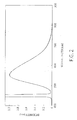
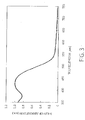
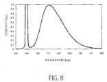
- each obtained fluorescent substance was analyzed by ICP spectroscopy. Further, the emission and absorption spectra of each fluorescent substance were measured with a fluorescence spectrophotometer (C9920-02G absolute quantum yield measurement system [trademark], manufactured by Hamamatsu Photonics K.K.).
- Figures 2 and 3 show the emission and absorption spectra in Example 1, respectively.
- Figures 4 and 5 show the emission and absorption spectra in Example 2, respectively.
- Table 2 and Figure 9 show a relation between the composition and the rate of absorption at the emission peak wavelength.
- Table 2 Composition Rate of absorption at the emission peak wavelength Com.1 (Sr 0.945 Ce 0.0195 ) 2 Si 7.5 Al 2.5 O 0.33 N 13.36 0.103 Ex.
Landscapes
- Chemical & Material Sciences (AREA)
- Inorganic Chemistry (AREA)
- Engineering & Computer Science (AREA)
- Materials Engineering (AREA)
- Organic Chemistry (AREA)
- Luminescent Compositions (AREA)
- Led Device Packages (AREA)
Applications Claiming Priority (1)
| Application Number | Priority Date | Filing Date | Title |
|---|---|---|---|
| JP2013054006A JP2014177601A (ja) | 2013-03-15 | 2013-03-15 | 黄色発光蛍光体およびそれを用いた発光装置 |
Publications (1)
| Publication Number | Publication Date |
|---|---|
| EP2778210A1 true EP2778210A1 (de) | 2014-09-17 |
Family
ID=50159140
Family Applications (1)
| Application Number | Title | Priority Date | Filing Date |
|---|---|---|---|
| EP20140156850 Withdrawn EP2778210A1 (de) | 2013-03-15 | 2014-02-26 | Fluoreszente Substanz und lichtemittierende Vorrichtung damit |
Country Status (6)
| Country | Link |
|---|---|
| US (1) | US20140265818A1 (de) |
| EP (1) | EP2778210A1 (de) |
| JP (1) | JP2014177601A (de) |
| KR (1) | KR20140113344A (de) |
| CN (1) | CN104046358A (de) |
| TW (1) | TW201437332A (de) |
Families Citing this family (2)
| Publication number | Priority date | Publication date | Assignee | Title |
|---|---|---|---|---|
| JP2014181260A (ja) * | 2013-03-18 | 2014-09-29 | Toshiba Corp | 蛍光体、発光装置、および蛍光体の製造方法 |
| US9528876B2 (en) | 2014-09-29 | 2016-12-27 | Innovative Science Tools, Inc. | Solid state broad band near-infrared light source |
Citations (5)
| Publication number | Priority date | Publication date | Assignee | Title |
|---|---|---|---|---|
| EP1296383A2 (de) * | 2001-09-20 | 2003-03-26 | Patent-Treuhand-Gesellschaft für elektrische Glühlampen mbH | Beleuchtungseinheit mit mindestens einer LED als Lichtquelle |
| US20060197439A1 (en) * | 2005-03-04 | 2006-09-07 | Dowa Mining Co., Ltd. | Phosphor and manufacturing method of the same, and light emitting device using the phosphor |
| EP1930393A1 (de) * | 2005-09-27 | 2008-06-11 | Dowa Mining Co., Ltd. | Fluoreszenzstoff, herstellungsverfahren dafür sowie davon gebrauch machende leuchtvorrichtung |
| US20100001234A1 (en) * | 2006-09-29 | 2010-01-07 | Dowa Electronics Materials Co., Ltd. | Manufacturing method of nitride phosphor or oxynitride phosphor |
| EP2463353A1 (de) * | 2009-08-06 | 2012-06-13 | Showa Denko K.K. | Fluoreszierende substanz, verfahren zu ihrer herstellung und lumineszierende vorrichtung damit |
Family Cites Families (1)
| Publication number | Priority date | Publication date | Assignee | Title |
|---|---|---|---|---|
| US9617469B2 (en) * | 2011-01-06 | 2017-04-11 | Shin-Etsu Chemical Co., Ltd. | Phosphor particles, making method, and light-emitting diode |
-
2013
- 2013-03-15 JP JP2013054006A patent/JP2014177601A/ja not_active Abandoned
-
2014
- 2014-02-17 TW TW103105104A patent/TW201437332A/zh unknown
- 2014-02-25 US US14/188,877 patent/US20140265818A1/en not_active Abandoned
- 2014-02-26 EP EP20140156850 patent/EP2778210A1/de not_active Withdrawn
- 2014-02-27 KR KR20140023072A patent/KR20140113344A/ko not_active Ceased
- 2014-03-04 CN CN201410075958.7A patent/CN104046358A/zh active Pending
Patent Citations (5)
| Publication number | Priority date | Publication date | Assignee | Title |
|---|---|---|---|---|
| EP1296383A2 (de) * | 2001-09-20 | 2003-03-26 | Patent-Treuhand-Gesellschaft für elektrische Glühlampen mbH | Beleuchtungseinheit mit mindestens einer LED als Lichtquelle |
| US20060197439A1 (en) * | 2005-03-04 | 2006-09-07 | Dowa Mining Co., Ltd. | Phosphor and manufacturing method of the same, and light emitting device using the phosphor |
| EP1930393A1 (de) * | 2005-09-27 | 2008-06-11 | Dowa Mining Co., Ltd. | Fluoreszenzstoff, herstellungsverfahren dafür sowie davon gebrauch machende leuchtvorrichtung |
| US20100001234A1 (en) * | 2006-09-29 | 2010-01-07 | Dowa Electronics Materials Co., Ltd. | Manufacturing method of nitride phosphor or oxynitride phosphor |
| EP2463353A1 (de) * | 2009-08-06 | 2012-06-13 | Showa Denko K.K. | Fluoreszierende substanz, verfahren zu ihrer herstellung und lumineszierende vorrichtung damit |
Also Published As
| Publication number | Publication date |
|---|---|
| KR20140113344A (ko) | 2014-09-24 |
| US20140265818A1 (en) | 2014-09-18 |
| TW201437332A (zh) | 2014-10-01 |
| JP2014177601A (ja) | 2014-09-25 |
| CN104046358A (zh) | 2014-09-17 |
Similar Documents
| Publication | Publication Date | Title |
|---|---|---|
| KR101246511B1 (ko) | 형광 물질, 형광 물질의 제조 방법, 발광 장치 및 발광 모듈 | |
| KR101434713B1 (ko) | 형광 물질 및 이를 사용한 발광 장치 | |
| KR101610565B1 (ko) | 형광체 및 제조 방법, 형광체를 사용하는 발광 장치 및 화상 표시 장치 | |
| JP5269163B2 (ja) | 精密に制御された元素組成物を有する蛍光体を提供する方法、同方法で提供された蛍光体、蛍光体、及び該蛍光体を含む発光デバイス | |
| JPWO2007004493A1 (ja) | 蛍光体とその製造方法および照明器具 | |
| JP6057213B2 (ja) | 蛍光体、その製造方法、発光装置および画像表示装置 | |
| WO2006080539A1 (ja) | 蛍光体とその製造方法および発光器具 | |
| JP6684412B1 (ja) | 蛍光体、その製造方法および発光装置 | |
| US20220154070A1 (en) | Nitride fluorescent material and light emission device | |
| US8652359B2 (en) | Red light-emitting fluorescent substance and light-emitting device employing the same | |
| CN107851694A (zh) | 发光器具和图像显示装置 | |
| KR102620016B1 (ko) | 적색 형광체 및 발광 장치 | |
| EP2778210A1 (de) | Fluoreszente Substanz und lichtemittierende Vorrichtung damit | |
| US9397272B2 (en) | Phosphor and light emitting device | |
| JP5646567B2 (ja) | 蛍光体の製造方法 | |
| JP2017052849A (ja) | 蛍光体、蛍光体の製造方法、およびそれを用いた発光装置 |
Legal Events
| Date | Code | Title | Description |
|---|---|---|---|
| PUAI | Public reference made under article 153(3) epc to a published international application that has entered the european phase |
Free format text: ORIGINAL CODE: 0009012 |
|
| 17P | Request for examination filed |
Effective date: 20140226 |
|
| AK | Designated contracting states |
Kind code of ref document: A1 Designated state(s): AL AT BE BG CH CY CZ DE DK EE ES FI FR GB GR HR HU IE IS IT LI LT LU LV MC MK MT NL NO PL PT RO RS SE SI SK SM TR |
|
| AX | Request for extension of the european patent |
Extension state: BA ME |
|
| STAA | Information on the status of an ep patent application or granted ep patent |
Free format text: STATUS: THE APPLICATION IS DEEMED TO BE WITHDRAWN |
|
| 18D | Application deemed to be withdrawn |
Effective date: 20160901 |