EP2780923B1 - Hvdc hybrid circuit breaker with snubber circuit - Google Patents
Hvdc hybrid circuit breaker with snubber circuit Download PDFInfo
- Publication number
- EP2780923B1 EP2780923B1 EP20110785666 EP11785666A EP2780923B1 EP 2780923 B1 EP2780923 B1 EP 2780923B1 EP 20110785666 EP20110785666 EP 20110785666 EP 11785666 A EP11785666 A EP 11785666A EP 2780923 B1 EP2780923 B1 EP 2780923B1
- Authority
- EP
- European Patent Office
- Prior art keywords
- breaker
- auxiliary
- disconnector
- circuit breaker
- series
- Prior art date
- Legal status (The legal status is an assumption and is not a legal conclusion. Google has not performed a legal analysis and makes no representation as to the accuracy of the status listed.)
- Active
Links
Images
Classifications
-
- H—ELECTRICITY
- H02—GENERATION; CONVERSION OR DISTRIBUTION OF ELECTRIC POWER
- H02H—EMERGENCY PROTECTIVE CIRCUIT ARRANGEMENTS
- H02H3/00—Emergency protective circuit arrangements for automatic disconnection directly responsive to an undesired change from normal electric working condition with or without subsequent reconnection ; integrated protection
- H02H3/20—Emergency protective circuit arrangements for automatic disconnection directly responsive to an undesired change from normal electric working condition with or without subsequent reconnection ; integrated protection responsive to excess voltage
- H02H3/22—Emergency protective circuit arrangements for automatic disconnection directly responsive to an undesired change from normal electric working condition with or without subsequent reconnection ; integrated protection responsive to excess voltage of short duration, e.g. lightning
-
- H—ELECTRICITY
- H01—ELECTRIC ELEMENTS
- H01H—ELECTRIC SWITCHES; RELAYS; SELECTORS; EMERGENCY PROTECTIVE DEVICES
- H01H9/00—Details of switching devices, not covered by groups H01H1/00 - H01H7/00
- H01H9/54—Circuit arrangements not adapted to a particular application of the switching device and for which no provision exists elsewhere
- H01H9/541—Contacts shunted by semiconductor devices
-
- H—ELECTRICITY
- H01—ELECTRIC ELEMENTS
- H01H—ELECTRIC SWITCHES; RELAYS; SELECTORS; EMERGENCY PROTECTIVE DEVICES
- H01H33/00—High-tension or heavy-current switches with arc-extinguishing or arc-preventing means
- H01H33/02—Details
- H01H33/59—Circuit arrangements not adapted to a particular application of the switch and not otherwise provided for, e.g. for ensuring operation of the switch at a predetermined point in the AC cycle
- H01H33/596—Circuit arrangements not adapted to a particular application of the switch and not otherwise provided for, e.g. for ensuring operation of the switch at a predetermined point in the AC cycle for interrupting DC
-
- H—ELECTRICITY
- H01—ELECTRIC ELEMENTS
- H01H—ELECTRIC SWITCHES; RELAYS; SELECTORS; EMERGENCY PROTECTIVE DEVICES
- H01H9/00—Details of switching devices, not covered by groups H01H1/00 - H01H7/00
- H01H9/54—Circuit arrangements not adapted to a particular application of the switching device and for which no provision exists elsewhere
- H01H9/541—Contacts shunted by semiconductor devices
- H01H9/542—Contacts shunted by static switch means
- H01H2009/544—Contacts shunted by static switch means the static switching means being an insulated gate bipolar transistor, e.g. IGBT, Darlington configuration of FET and bipolar transistor
-
- H—ELECTRICITY
- H01—ELECTRIC ELEMENTS
- H01H—ELECTRIC SWITCHES; RELAYS; SELECTORS; EMERGENCY PROTECTIVE DEVICES
- H01H9/00—Details of switching devices, not covered by groups H01H1/00 - H01H7/00
- H01H9/54—Circuit arrangements not adapted to a particular application of the switching device and for which no provision exists elsewhere
- H01H9/541—Contacts shunted by semiconductor devices
- H01H9/542—Contacts shunted by static switch means
- H01H2009/546—Contacts shunted by static switch means the static switching means being triggered by the voltage over the mechanical switch contacts
Definitions
- the invention relates in general to high voltage direct current (HVDC) hybrid circuit breakers, and more specifically to snubber circuits in such circuit breakers.
- HVDC high voltage direct current
- HVDC hybrid circuit breakers such as disclosed in WO 2011/057675 , are typically based on a combination of a solid-state main breaker connected in parallel to a series-connection of a solid-state auxiliary breaker and a mechanical disconnector.
- the principal of operation of a hybrid circuit breaker is that the main breaker, the auxiliary breaker, and the disconnector are closed during normal operation. If a trip signal is received, the hybrid circuit breaker attempts to break the current flowing through it by first opening the auxiliary breaker, thereby commutating the current flowing through the auxiliary breaker and the disconnector to the main breaker. Subsequently, the disconnector is opened for disconnecting the auxiliary breaker, and finally the main breaker is opened, resulting in a commutation of the current from the main breaker to a surge arrester connected in parallel to the main breaker.
- hybrid circuit breakers are supplied with snubber circuits in order to suppress voltage transients which arise in response to the sudden interruption of the current when the disconnector is opened.
- a snubber circuit typically comprises a capacitor which is connected in parallel to the auxiliary breaker.
- DC direct current
- Embodiments of the invention are characterized by the dependent claims.
- a DC circuit breaker comprises a main breaker, a disconnector, an auxiliary breaker, and a snubber circuit.
- the disconnector and the auxiliary breaker are connected in series.
- the series-connection of the disconnector and the auxiliary breaker is connected in parallel to the main breaker.
- the snubber circuit comprises a capacitor.
- the capacitor is connected in parallel to the auxiliary breaker.
- the circuit breaker further comprises switching means.
- the switching means is arranged for disconnecting the snubber capacitor.
- the snubber capacitor is disconnected in response to the auxiliary breaker being opened.
- a method of a DC circuit breaker comprises a main breaker, a disconnector, an auxiliary breaker, and a snubber circuit.
- the disconnector and the auxiliary breaker are connected in series.
- the series-connection of the disconnector and the auxiliary breaker is connected in parallel to the main breaker.
- the snubber circuit comprises a capacitor.
- the capacitor is connected in parallel to the auxiliary breaker.
- the method comprises disconnecting the snubber capacitor.
- the snubber capacitor is disconnected in response to the auxiliary breaker being opened.
- the present invention makes use of an understanding that an uncontrolled discharging of the snubber capacitor during the breaking operation of an HVDC hybrid circuit breaker may be prevented by providing the circuit breaker with switching means which is arranged for disconnecting the capacitor in response to the auxiliary breaker being opened.
- the switching means is opened when the auxiliary breaker is opened.
- a control unit being arranged for controlling the hybrid circuit breaker, may further be arranged for controlling the switching means so as to open the switching means at the same time as the auxiliary breaker, or shortly after.
- the switching means may be arranged for detecting a state, or a state change, of the auxiliary breaker.
- the latter may, e.g., be achieved by receiving a signal from the control unit of the hybrid circuit breaker, the signal being indicative of the state, or a state change, of the auxiliary breaker.
- the switching means may also be provided with means for detecting a state change of the auxiliary breaker by monitoring the voltage over, and/or the current through, the snubber capacitor. In this case, a sudden change in the measured quantities may be indicative of the auxiliary breaker being opened.
- An embodiment of the invention is advantageous since the problems associated with prior art hybrid circuit breakers, which problems arise due to a discharging current flowing from the capacitor through the disconnector and the main breaker, are mitigated. More specifically, the non-zero current flowing through the disconnector of a prior art hybrid circuit breaker impedes the breaking action of the disconnector. In an embodiment of the present invention on the other hand, an uncontrolled discharging of the capacitor is prevented, thereby allowing the disconnector to break the current.
- the switching means is connected in series with the snubber capacitor.
- the switching means comprises a power semiconductor switching element.
- the switching means and/or the power semiconductor switching element comprises one or more of an insulated gate bipolar transistor (IGBT) and a bi-mode insulated gate transistor (BiGT).
- IGBT insulated gate bipolar transistor
- BiGT bi-mode insulated gate transistor
- the main breaker comprises a plurality of power semiconductor switching elements.
- the switching elements are connected in series.
- the disconnector comprises a mechanical switch.
- the auxiliary breaker comprises a power semiconductor switching element.
- the auxiliary breaker may comprise a plurality of power semiconductor switching elements connected in series and/or in parallel.
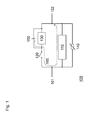
- Hybrid circuit breaker 100 comprises a main breaker 110, a fast disconnector, i.e., a high-speed switch, 120, an auxiliary breaker 130, a surge arrester 140, and a snubber capacitor 150.
- Disconnector 120 and auxiliary breaker 130 are connected in series, and the series connection of disconnector 120 and auxiliary breaker 130 is connected in parallel to main breaker 110.
- Surge arrester 140 is connected in parallel to main breaker 110 and the series-connection of disconnector 120 and auxiliary breaker 130.
- Snubber capacitor 150 is connected in parallel to auxiliary breaker 130.
- Hybrid circuit breaker 100 may be connected to an external circuit, such as an HVDC transmission line, at terminals 101 and 102.
- hybrid circuit breaker 100 may be used to connect an HVDC transmission line to a busbar of a switchyard, for the purpose of disconnecting the transmission line from the busbar in the event of a failure, or for maintenance.
- hybrid circuit breaker 100 During normal operation, main breaker 110, disconnector 120, and auxiliary breaker 130, are closed. If a trip signal is received by hybrid circuit breaker 100, circuit breaker 100 attempts to break the current flowing through it, i.e., from terminal 101 to 102, or vice versa, by first opening auxiliary breaker 130, thereby commutating the current flowing through auxiliary breaker 130 and disconnector 120 to main breaker 110. Subsequently, disconnector 120 is opened for disconnecting auxiliary breaker 130, and finally main breaker 110 is opened, resulting in a commutation of the current from main breaker 110 to surge arrester 140.
- Hybrid circuit breaker 100 is equipped with snubber capacitor 150 for the purpose of suppressing voltage transients across auxiliary breaker 130 which arise in response to the sudden interruption of the current when auxiliary breaker 130 is opened. Even though hybrid circuit breaker 100 has been described as comprising a snubber capacitor 150, it will be appreciated that more advanced snubber circuits 120 may be utilized.
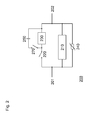
- Hybrid circuit breaker 200 is similar to circuit breaker 100, described with reference to Fig. 1 , in that it comprises a main breaker 210, a fast disconnector, i.e., a high-speed switch, 220, an auxiliary breaker 230, a surge arrester 240, and a snubber capacitor 250.
- Disconnector 220 and auxiliary breaker 230 are connected in series, and the series connection of disconnector 220 and auxiliary breaker 230 is connected in parallel to main breaker 210.
- Surge arrester 240 is connected in parallel to main breaker 210 and the series-connection of disconnector 220 and auxiliary breaker 230.
- Snubber capacitor 250 is connected in parallel to auxiliary breaker 230.
- Hybrid circuit breaker 200 may be connected to an external circuit, such as an HVDC transmission line, at terminals 201 and 202.
- hybrid circuit breaker 200 may be used to connect an HVDC transmission line to a busbar of a switchyard, for the purpose of disconnecting the transmission line from the busbar in the event of a failure, or for maintenance.
- Main breaker 210, disconnector 220, and auxiliary breaker 230 may be based on different types of breaker technologies.
- main breaker 210 and auxiliary breaker 230 may be based on solid-state switches, i.e., power semiconductor devices, such as transistors or thyristors, as is elucidated further below.
- main breaker 210 and auxiliary breaker 230 may comprise a plurality of solid-state switches connected in series.
- main breaker 210 and auxiliary breaker 230 may be based on power semiconductor switching elements connected in parallel.
- Disconnector 220 may, e.g., be based on a mechanical switch.
- Hybrid circuit breaker 200 is further configured with switching means 270, which is arranged for preventing an uncontrolled discharging of snubber capacitor 250 via disconnector 220 and main breaker 210, as was described hereinabove with reference to Fig. 1 .
- switching means 270 which is connected in series with capacitor 250, is opened together with auxiliary breaker 230, thereby disconnecting capacitor 250.
- the discharging of capacitor 250 is prevented, thereby eliminating the non-zero current through disconnector 220 during the breaking action of disconnector 220.
- disconnector 220 may break the current and disconnect auxiliary breaker 230.
- Switching means 270 may, e.g., be based on solid-state switches of the same or a similar type as main breaker 210 and auxiliary breaker 230.
- Switching means 270 may for example comprise an insulated gate bipolar transistor (IGBT) or a bi-mode insulated gate transistor (BiGT).
- IGBT insulated gate bipolar transistor
- BiGT bi-mode insulated gate transistor
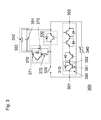
- FIG. 3 a further embodiment of a hybrid circuit breaker in accordance with the invention is illustrated.
- Hybrid circuit breaker 300 comprises a main breaker 310, a fast disconnector, i.e., a high-speed switch, 320, an auxiliary breaker 330, a surge arrester 340, a snubber circuit 350, and switching means 370.
- Disconnector 320 and auxiliary breaker 330 are connected in series, and the series connection of disconnector 320 and auxiliary breaker 330 is connected in parallel to main breaker 310.
- Surge arrester 340 is connected in parallel to main breaker 310 and the series-connection of disconnector 320 and auxiliary breaker 330.
- Snubber circuit 350 is connected in parallel to auxiliary breaker 330.
- Switching means 370 is connected in series with snubber circuit 350 and is arranged for preventing an uncontrolled discharging of snubber capacitor 350, as was described hereinbefore.
- hybrid circuit breaker 300 may be connected to an external circuit, such as an HVDC transmission line, at terminals 301 and 302.
- an external circuit such as an HVDC transmission line
- main breaker 310 is based on a series-connection of power semiconductor switching elements 380.
- Power semiconductor switching element 380 may, e.g., be based on an insulated gate bipolar transistor (IGBT) 381 and a diode 382 connected anti-parallel to transistor 381.
- IGBT insulated gate bipolar transistor
- Auxiliary breaker 330 may be based on the same or similar type of power semiconductor switching element 380.
- auxiliary breaker 330 may comprise a plurality of switching elements connected in series and/or in parallel. It will also be appreciated that main breaker 310 and auxiliary breaker 330 may comprise power semiconductor switching elements connected in parallel, thereby increasing the current rating of the respective breaker.
- Snubber circuit 350 comprises a capacitor 351 and a resistor 352 connected in parallel.
- Switching means 370 comprises a switching element 371, such as power semiconductor switching element 380 or similar, connected in series with a resistor 372.
- the series-connection of switching element 371 and resistor 372 is connected parallel to a diode 373.
- Switching means 370 and/or switching element 371 may for example comprise an IGBT or a BiGT.
- Main breaker 310, disconnector 320, auxiliary breaker 330, and switching means 370, in particular power semiconductor switching element 371, are controlled by a control unit (not shown in Fig. 3 ).
- the control unit may either be arranged at hybrid circuit breaker 300 or at an external unit, such as a control unit of an HVDC switchyard.
- an HVDC hybrid circuit breaker comprises a solid-state main breaker, a mechanical fast disconnector and a solid-state auxiliary breaker connected in series, the series-connection of the disconnector and the auxiliary breaker being connected in parallel to the main breaker, a snubber circuit comprising a capacitor, and switching means being arranged for disconnecting the snubber capacitor in response to the auxiliary breaker being opened.
Landscapes
- Engineering & Computer Science (AREA)
- Power Engineering (AREA)
- Driving Mechanisms And Operating Circuits Of Arc-Extinguishing High-Tension Switches (AREA)
Description
- The invention relates in general to high voltage direct current (HVDC) hybrid circuit breakers, and more specifically to snubber circuits in such circuit breakers.
- HVDC hybrid circuit breakers, such as disclosed in
WO 2011/057675 , are typically based on a combination of a solid-state main breaker connected in parallel to a series-connection of a solid-state auxiliary breaker and a mechanical disconnector. The principal of operation of a hybrid circuit breaker is that the main breaker, the auxiliary breaker, and the disconnector are closed during normal operation. If a trip signal is received, the hybrid circuit breaker attempts to break the current flowing through it by first opening the auxiliary breaker, thereby commutating the current flowing through the auxiliary breaker and the disconnector to the main breaker. Subsequently, the disconnector is opened for disconnecting the auxiliary breaker, and finally the main breaker is opened, resulting in a commutation of the current from the main breaker to a surge arrester connected in parallel to the main breaker. - Frequently, hybrid circuit breakers are supplied with snubber circuits in order to suppress voltage transients which arise in response to the sudden interruption of the current when the disconnector is opened. A snubber circuit typically comprises a capacitor which is connected in parallel to the auxiliary breaker.
- When the breaking operation of the hybrid circuit breaker is initiated by opening the auxiliary breaker, the snubber capacitor is charged, but as soon as the current commutates from the auxiliary breaker to the main breaker, the capacitor is discharged through the disconnector and the main breaker. This discharging process, and the resulting non-zero current through the disconnector, hinders the breaking operation of the disconnector.
- Another exaple of HVDC circuit breaker is disclosed in
EP-A-0660352 . - It is an object of the present invention to provide a more efficient alternative to the above techniques and prior art.
- More specifically, it is an object of the present invention to provide an improved HVDC hybrid circuit breaker.
- These and other objects of the present invention are achieved by means of direct current (DC) circuit breaker having the features defined in independent claim 1, and by means of the method of claim 9.
- Embodiments of the invention are characterized by the dependent claims.
- According to a first aspect of the invention, a DC circuit breaker is provided. The circuit breaker comprises a main breaker, a disconnector, an auxiliary breaker, and a snubber circuit. The disconnector and the auxiliary breaker are connected in series. The series-connection of the disconnector and the auxiliary breaker is connected in parallel to the main breaker. The snubber circuit comprises a capacitor. The capacitor is connected in parallel to the auxiliary breaker. The circuit breaker further comprises switching means. The switching means is arranged for disconnecting the snubber capacitor. The snubber capacitor is disconnected in response to the auxiliary breaker being opened.
- According to a second aspect of the invention, a method of a DC circuit breaker is provided. The circuit breaker comprises a main breaker, a disconnector, an auxiliary breaker, and a snubber circuit. The disconnector and the auxiliary breaker are connected in series. The series-connection of the disconnector and the auxiliary breaker is connected in parallel to the main breaker. The snubber circuit comprises a capacitor. The capacitor is connected in parallel to the auxiliary breaker. The method comprises disconnecting the snubber capacitor. The snubber capacitor is disconnected in response to the auxiliary breaker being opened.
- The present invention makes use of an understanding that an uncontrolled discharging of the snubber capacitor during the breaking operation of an HVDC hybrid circuit breaker may be prevented by providing the circuit breaker with switching means which is arranged for disconnecting the capacitor in response to the auxiliary breaker being opened. In other words, the switching means is opened when the auxiliary breaker is opened. For instance, a control unit being arranged for controlling the hybrid circuit breaker, may further be arranged for controlling the switching means so as to open the switching means at the same time as the auxiliary breaker, or shortly after. As an alternative, the switching means may be arranged for detecting a state, or a state change, of the auxiliary breaker. The latter may, e.g., be achieved by receiving a signal from the control unit of the hybrid circuit breaker, the signal being indicative of the state, or a state change, of the auxiliary breaker. As a further alternative, the switching means may also be provided with means for detecting a state change of the auxiliary breaker by monitoring the voltage over, and/or the current through, the snubber capacitor. In this case, a sudden change in the measured quantities may be indicative of the auxiliary breaker being opened.
- An embodiment of the invention is advantageous since the problems associated with prior art hybrid circuit breakers, which problems arise due to a discharging current flowing from the capacitor through the disconnector and the main breaker, are mitigated. More specifically, the non-zero current flowing through the disconnector of a prior art hybrid circuit breaker impedes the breaking action of the disconnector. In an embodiment of the present invention on the other hand, an uncontrolled discharging of the capacitor is prevented, thereby allowing the disconnector to break the current.
- According to an embodiment of the invention, the switching means is connected in series with the snubber capacitor.
- According to an embodiment of the invention, the switching means comprises a power semiconductor switching element.
- According to an embodiment of the invention, the switching means and/or the power semiconductor switching element comprises one or more of an insulated gate bipolar transistor (IGBT) and a bi-mode insulated gate transistor (BiGT).
- According to an embodiment of the invention, the main breaker comprises a plurality of power semiconductor switching elements. The switching elements are connected in series.
- According to an embodiment of the invention, the disconnector comprises a mechanical switch.
- According to an embodiment of the invention, the auxiliary breaker comprises a power semiconductor switching element. Further, the auxiliary breaker may comprise a plurality of power semiconductor switching elements connected in series and/or in parallel.
- Even though advantages of the present invention have in some cases been described with reference to embodiments of the hybrid circuit breaker according to the first aspect of the invention, corresponding reasoning applies to embodiments of the method according to the second aspect of the invention.
- Further objectives of, features of, and advantages with, the present invention will become apparent when studying the following detailed disclosure, the drawings and the appended claims. Those skilled in the art realize that different features of the present invention can be combined to create embodiments other than those described in the following.
- The above, as well as additional objects, features and advantages of the present invention, will be better understood through the following illustrative and non-limiting detailed description of embodiments of the present invention, with reference to the appended drawings, in which:
-
Fig. 1 is a schematic illustration of a prior art HVDC hybrid circuit breaker. -
Fig. 2 is a schematic illustration of an HVDC hybrid circuit breaker in accordance with an embodiment of the invention. -
Fig. 3 shows an HVDC hybrid circuit breaker in accordance with another embodiment of the invention. - All the figures are schematic, not necessarily to scale, and generally only show parts which are necessary in order to elucidate the invention, wherein other parts may be omitted or merely suggested.
- With reference to
Fig. 1 , a prior art HVDC hybrid circuit breaker is described. -
Hybrid circuit breaker 100 comprises amain breaker 110, a fast disconnector, i.e., a high-speed switch, 120, anauxiliary breaker 130, asurge arrester 140, and asnubber capacitor 150. Disconnector 120 andauxiliary breaker 130 are connected in series, and the series connection ofdisconnector 120 andauxiliary breaker 130 is connected in parallel tomain breaker 110.Surge arrester 140 is connected in parallel tomain breaker 110 and the series-connection ofdisconnector 120 andauxiliary breaker 130.Snubber capacitor 150 is connected in parallel toauxiliary breaker 130. -
Hybrid circuit breaker 100 may be connected to an external circuit, such as an HVDC transmission line, atterminals hybrid circuit breaker 100 may be used to connect an HVDC transmission line to a busbar of a switchyard, for the purpose of disconnecting the transmission line from the busbar in the event of a failure, or for maintenance. - In the following, the principal of operation of
hybrid circuit breaker 100 is described. During normal operation,main breaker 110,disconnector 120, andauxiliary breaker 130, are closed. If a trip signal is received byhybrid circuit breaker 100,circuit breaker 100 attempts to break the current flowing through it, i.e., fromterminal 101 to 102, or vice versa, by first openingauxiliary breaker 130, thereby commutating the current flowing throughauxiliary breaker 130 anddisconnector 120 tomain breaker 110. Subsequently,disconnector 120 is opened for disconnectingauxiliary breaker 130, and finallymain breaker 110 is opened, resulting in a commutation of the current frommain breaker 110 to surgearrester 140. -
Hybrid circuit breaker 100 is equipped withsnubber capacitor 150 for the purpose of suppressing voltage transients acrossauxiliary breaker 130 which arise in response to the sudden interruption of the current whenauxiliary breaker 130 is opened. Even thoughhybrid circuit breaker 100 has been described as comprising asnubber capacitor 150, it will be appreciated that moreadvanced snubber circuits 120 may be utilized. - A problem which arises in prior art hybrid circuit breakers, such as
hybrid circuit breaker 100 described with reference toFig. 1 , is that the chargedsnubber capacitor 150 is discharged throughdisconnector 120 andmain breaker 110 whenauxiliary breaker 130 is opened, as is illustrated byarrow 160 inFig. 1 . As a consequence of the non-zero current flowing throughdisconnector 120, the breaking action ofdisconnector 120 is hindered. - In the following, an embodiment of the invention is described with reference to
Fig. 2 . -
Hybrid circuit breaker 200 is similar tocircuit breaker 100, described with reference toFig. 1 , in that it comprises amain breaker 210, a fast disconnector, i.e., a high-speed switch, 220, anauxiliary breaker 230, asurge arrester 240, and asnubber capacitor 250.Disconnector 220 andauxiliary breaker 230 are connected in series, and the series connection ofdisconnector 220 andauxiliary breaker 230 is connected in parallel tomain breaker 210.Surge arrester 240 is connected in parallel tomain breaker 210 and the series-connection ofdisconnector 220 andauxiliary breaker 230.Snubber capacitor 250 is connected in parallel toauxiliary breaker 230. -
Hybrid circuit breaker 200 may be connected to an external circuit, such as an HVDC transmission line, atterminals hybrid circuit breaker 200 may be used to connect an HVDC transmission line to a busbar of a switchyard, for the purpose of disconnecting the transmission line from the busbar in the event of a failure, or for maintenance. -
Main breaker 210,disconnector 220, andauxiliary breaker 230 may be based on different types of breaker technologies. For instance,main breaker 210 andauxiliary breaker 230 may be based on solid-state switches, i.e., power semiconductor devices, such as transistors or thyristors, as is elucidated further below. In order to achieve higher voltage ratings,main breaker 210 andauxiliary breaker 230 may comprise a plurality of solid-state switches connected in series. Further, in order to increase the current rating,main breaker 210 andauxiliary breaker 230 may be based on power semiconductor switching elements connected in parallel.Disconnector 220 may, e.g., be based on a mechanical switch. -
Hybrid circuit breaker 200 is further configured with switching means 270, which is arranged for preventing an uncontrolled discharging ofsnubber capacitor 250 viadisconnector 220 andmain breaker 210, as was described hereinabove with reference toFig. 1 . To this end, switching means 270, which is connected in series withcapacitor 250, is opened together withauxiliary breaker 230, thereby disconnectingcapacitor 250. As a consequence, the discharging ofcapacitor 250 is prevented, thereby eliminating the non-zero current throughdisconnector 220 during the breaking action ofdisconnector 220. In that way, the problems associated with prior art hybrid circuit breakers, such ascircuit breaker 100, are mitigated, anddisconnector 220 may break the current and disconnectauxiliary breaker 230. - Switching means 270 may, e.g., be based on solid-state switches of the same or a similar type as
main breaker 210 andauxiliary breaker 230. Switching means 270 may for example comprise an insulated gate bipolar transistor (IGBT) or a bi-mode insulated gate transistor (BiGT). - In
Fig. 3 , a further embodiment of a hybrid circuit breaker in accordance with the invention is illustrated. -
Hybrid circuit breaker 300 comprises amain breaker 310, a fast disconnector, i.e., a high-speed switch, 320, anauxiliary breaker 330, asurge arrester 340, asnubber circuit 350, and switching means 370.Disconnector 320 andauxiliary breaker 330 are connected in series, and the series connection ofdisconnector 320 andauxiliary breaker 330 is connected in parallel tomain breaker 310.Surge arrester 340 is connected in parallel tomain breaker 310 and the series-connection ofdisconnector 320 andauxiliary breaker 330.Snubber circuit 350 is connected in parallel toauxiliary breaker 330. Switching means 370 is connected in series withsnubber circuit 350 and is arranged for preventing an uncontrolled discharging ofsnubber capacitor 350, as was described hereinbefore. - Similar to
circuit breakers hybrid circuit breaker 300 may be connected to an external circuit, such as an HVDC transmission line, atterminals - Further with reference to
Fig. 3 ,main breaker 310 is based on a series-connection of powersemiconductor switching elements 380. Powersemiconductor switching element 380 may, e.g., be based on an insulated gate bipolar transistor (IGBT) 381 and adiode 382 connected anti-parallel totransistor 381.Auxiliary breaker 330 may be based on the same or similar type of powersemiconductor switching element 380. Further,auxiliary breaker 330 may comprise a plurality of switching elements connected in series and/or in parallel. It will also be appreciated thatmain breaker 310 andauxiliary breaker 330 may comprise power semiconductor switching elements connected in parallel, thereby increasing the current rating of the respective breaker. -
Snubber circuit 350 comprises acapacitor 351 and aresistor 352 connected in parallel. - Switching means 370 comprises a
switching element 371, such as powersemiconductor switching element 380 or similar, connected in series with aresistor 372. The series-connection of switchingelement 371 andresistor 372 is connected parallel to adiode 373. - Switching means 370 and/or switching
element 371 may for example comprise an IGBT or a BiGT. -
Main breaker 310,disconnector 320,auxiliary breaker 330, and switching means 370, in particular powersemiconductor switching element 371, are controlled by a control unit (not shown inFig. 3 ). The control unit may either be arranged athybrid circuit breaker 300 or at an external unit, such as a control unit of an HVDC switchyard. - The person skilled in the art realizes that the present invention by no means is limited to the embodiments described above. On the contrary, many modifications and variations are possible within the scope of the appended claims.
- In conclusion, an HVDC hybrid circuit breaker is provided. The circuit breaker comprises a solid-state main breaker, a mechanical fast disconnector and a solid-state auxiliary breaker connected in series, the series-connection of the disconnector and the auxiliary breaker being connected in parallel to the main breaker, a snubber circuit comprising a capacitor, and switching means being arranged for disconnecting the snubber capacitor in response to the auxiliary breaker being opened. By disconnecting the snubber capacitor, an uncontrolled discharging of the capacitor through the disconnector and the main breaker, and the resulting non-zero current flowing through the disconnector during the breaking action, may be avoided. Further, a method of operating the HVDC hybrid circuit breaker is provided.
Claims (9)
- A direct current, DC, circuit breaker (200; 300) comprising:a main breaker (210; 310),a disconnector (220; 320) and an auxiliary breaker (230; 330) connected in series,a snubber circuit comprising a capacitor (250; 351), the capacitor being connected in parallel to the auxiliary breaker,characterised in that the series-connection of the disconnector (220; 320) and the auxiliary breaker (230; 330) is connected in parallel to the main breaker (210; 310),wherein the circuit breaker further comprises switching means (270; 371) being arranged for disconnecting the snubber capacitor in response to the auxiliary breaker being opened.
- The DC circuit breaker according to claim 1, wherein the switching means is connected in series with the snubber capacitor.
- The DC circuit breaker according to claim 1, wherein the switching means comprises a power semiconductor switching element (371, 380).
- The DC circuit breaker according to claim 3, wherein the power semiconductor switching element comprises an insulated gate bipolar transistor, IGBT (381).
- The DC circuit breaker according to claim 3, wherein the power semiconductor switching element comprises a bi-mode insulated gate transistor, BiGT.
- The DC circuit breaker according to claim 1, wherein the main breaker comprises a plurality of series-connected power semiconductor switching elements (380).
- The DC circuit breaker according to claim 1, wherein the disconnector comprises a mechanical switch.
- The DC circuit breaker according to claim 1, wherein the auxiliary breaker comprises a power semiconductor switching element (330, 380).
- A method of operating the direct current, DC, circuit breaker (200; 300) of claim 1, wherein the method comprises disconnecting the snubber capacitor in response to the auxiliary breaker being opened.
Applications Claiming Priority (1)
| Application Number | Priority Date | Filing Date | Title |
|---|---|---|---|
| PCT/EP2011/070484 WO2013071980A1 (en) | 2011-11-18 | 2011-11-18 | Hvdc hybrid circuit breaker with snubber circuit |
Publications (2)
| Publication Number | Publication Date |
|---|---|
| EP2780923A1 EP2780923A1 (en) | 2014-09-24 |
| EP2780923B1 true EP2780923B1 (en) | 2015-04-22 |
Family
ID=45002952
Family Applications (1)
| Application Number | Title | Priority Date | Filing Date |
|---|---|---|---|
| EP20110785666 Active EP2780923B1 (en) | 2011-11-18 | 2011-11-18 | Hvdc hybrid circuit breaker with snubber circuit |
Country Status (4)
| Country | Link |
|---|---|
| US (1) | US8891209B2 (en) |
| EP (1) | EP2780923B1 (en) |
| CN (1) | CN104137211B (en) |
| WO (1) | WO2013071980A1 (en) |
Cited By (2)
| Publication number | Priority date | Publication date | Assignee | Title |
|---|---|---|---|---|
| CN106711930A (en) * | 2015-07-24 | 2017-05-24 | 国网智能电网研究院 | DC circuit breaker and control method thereof |
| EP3206286A1 (en) | 2016-02-10 | 2017-08-16 | GE Energy Power Conversion Technology Ltd | Gatespannungsübersteuerung für das schalten von stossströmen in igbt schaltern |
Families Citing this family (58)
| Publication number | Priority date | Publication date | Assignee | Title |
|---|---|---|---|---|
| CA2768750C (en) | 2009-07-31 | 2017-01-31 | Areva T&D Uk Limited | Configurable hybrid converter circuit |
| WO2012044369A1 (en) | 2010-09-30 | 2012-04-05 | Abb Research Ltd. | Coordinated control of multi-terminal hvdc systems |
| EP2719062B1 (en) | 2011-06-08 | 2018-02-28 | General Electric Technology GmbH | High voltage dc/dc converter with cascaded resonant tanks |
| EP2740204B1 (en) | 2011-08-01 | 2020-09-30 | General Electric Technology GmbH | A dc to dc converter assembly |
| CN103959634B (en) | 2011-11-17 | 2017-09-01 | 通用电气技术有限公司 | The mixing AC/DC converters applied for HVDC |
| WO2013127463A1 (en) * | 2012-03-01 | 2013-09-06 | Alstom Technology Ltd | High voltage dc circuit breaker apparatus |
| CN104160572B (en) | 2012-03-01 | 2017-03-01 | 阿尔斯通技术有限公司 | Control circuit |
| CN104272416A (en) * | 2012-03-01 | 2015-01-07 | 阿尔斯通技术有限公司 | Composite high voltage DC circuit breaker |
| DE102013214627A1 (en) * | 2013-07-26 | 2015-01-29 | Siemens Aktiengesellschaft | DC switching apparatus |
| CN103746336B (en) * | 2013-12-16 | 2016-08-17 | 陈小龙 | A kind of Superfast leakage switch and control method thereof |
| US10320308B2 (en) | 2014-04-04 | 2019-06-11 | Siemens Aktiengesellschaft | Commutating circuit |
| EP2978005B1 (en) * | 2014-07-25 | 2017-05-17 | General Electric Technology GmbH | Current cut-off device on a transmission line |
| KR101641511B1 (en) * | 2014-09-18 | 2016-07-29 | 한국전기연구원 | Device for interrupting DC current and method the same |
| EP3001552A1 (en) | 2014-09-23 | 2016-03-30 | Alstom Technology Ltd | Voltage source converter and control thereof |
| JP6049957B2 (en) * | 2014-09-26 | 2016-12-21 | 三菱電機株式会社 | DC circuit breaker |
| FR3030105B1 (en) * | 2014-12-11 | 2017-05-26 | Inst Supergrid | HIGH VOLTAGE CONTINUOUS CURRENT CUTTING DEVICE |
| KR102167948B1 (en) * | 2014-12-31 | 2020-10-20 | 엘에스일렉트릭(주) | Dc circuit breaker and method for breaking of dc circuit breaker |
| EP3041015B1 (en) * | 2015-01-05 | 2020-03-25 | General Electric Technology GmbH | DC breaker |
| EP3051643B1 (en) * | 2015-01-30 | 2017-09-06 | General Electric Technology GmbH | Dc circuit breaker with counter current generation |
| CN104638605B (en) * | 2015-02-04 | 2018-02-23 | 华中科技大学 | A kind of capacitive buffer formula mixed high-voltage dc circuit breaker and its control method |
| EP3276648B1 (en) * | 2015-03-24 | 2020-01-29 | Kabushiki Kaisha Toshiba | Direct current interruption device |
| GB2541465A (en) * | 2015-08-21 | 2017-02-22 | General Electric Technology Gmbh | Electrical assembly |
| US10230260B2 (en) * | 2015-09-23 | 2019-03-12 | Abb Schweiz Ag | Fast utility disconnect switch for single conversion UPS |
| EP3157034B1 (en) | 2015-10-13 | 2018-03-21 | General Electric Technology GmbH | Mechatronic circuit-breaker device |
| CN105609344B (en) * | 2016-03-22 | 2019-06-11 | 国网天津市电力公司 | A hybrid DC circuit breaker topology |
| CN105680409B (en) * | 2016-04-19 | 2018-03-30 | 南京南瑞继保电气有限公司 | A kind of bridge circuit, DC current break-up device and its control method |
| CN105790236B (en) * | 2016-04-19 | 2018-03-13 | 南京南瑞继保电气有限公司 | A kind of DC current cutoff device and its control method |
| DE102016117004A1 (en) * | 2016-09-09 | 2018-03-15 | Eaton Industries (Austria) Gmbh | Protection device |
| CN106452035B (en) * | 2016-10-21 | 2019-05-24 | 四川大学 | A kind of buffer circuit suitable for hybrid high voltage DC breaker two-way series load current-change switch |
| DE102016120070A1 (en) * | 2016-10-21 | 2018-04-26 | Eaton Industries (Austria) Gmbh | Low-voltage protection device |
| CN106655746B (en) * | 2016-10-21 | 2019-12-03 | 四川大学 | A snubber circuit suitable for bidirectional parallel load commutation switch of hybrid HVDC circuit breaker |
| DE102016121835A1 (en) * | 2016-11-15 | 2018-05-17 | Eaton Industries (Austria) Gmbh | Low-voltage protection device |
| CN106655081B (en) * | 2016-11-30 | 2019-03-01 | 平高集团有限公司 | A DC circuit breaker and its control method |
| GB2560887A (en) | 2017-03-21 | 2018-10-03 | Gridon Ltd | AC switching arrangement |
| DE102017127076A1 (en) | 2017-11-17 | 2019-05-23 | Eaton Industries (Austria) Gmbh | Mechatronics module with a hybrid circuit arrangement |
| DE102018101312A1 (en) | 2018-01-22 | 2019-07-25 | Eaton Intelligent Power Limited | Electrical protection circuitry |
| DE102018101311A1 (en) | 2018-01-22 | 2019-07-25 | Eaton Intelligent Power Limited | Electrical protection switching arrangement |
| DE102018101677A1 (en) * | 2018-01-25 | 2019-07-25 | Eaton Intelligent Power Limited | Low-voltage protection device |
| CN108988295A (en) * | 2018-08-17 | 2018-12-11 | 中车永济电机有限公司 | It is quick break protective device in permanent magnet direct-drive system using one kind that IGBT is realized |
| WO2020061547A1 (en) * | 2018-09-21 | 2020-03-26 | North Carolina State University | Control of direct current circuit breakers with series semiconductor switches |
| US11646575B2 (en) | 2018-10-24 | 2023-05-09 | The Florida State University Research Foundation, Inc. | Direct current hybrid circuit breaker with reverse biased voltage source |
| US11424093B2 (en) | 2018-10-24 | 2022-08-23 | The Florida State University Research Foundation, Inc. | Direct current hybrid circuit breaker with reverse biased voltage source |
| WO2020101741A1 (en) * | 2018-11-13 | 2020-05-22 | Illinois Institute Of Technology | Hybrid circuit breaker using a transient commutation current injector circuit |
| FR3091408B1 (en) | 2018-12-27 | 2021-01-15 | Inst Supergrid | High voltage direct current cut-off device with adaptive oscillation circuit and control method |
| FR3091407B1 (en) | 2018-12-27 | 2021-10-29 | Inst Supergrid | High voltage direct current cut-off device with capacitive buffer circuit and control method |
| US12033818B2 (en) | 2018-12-31 | 2024-07-09 | Hitachi Energy Ltd | Circuit breaker having internal transient recovery voltage capacitor assembly |
| GB2581992A (en) * | 2019-03-06 | 2020-09-09 | Eaton Intelligent Power Ltd | Circuit breaker |
| FR3094136B1 (en) | 2019-03-22 | 2021-04-02 | Inst Supergrid | High voltage direct current cut-off device with resonator and commutation |
| WO2021119938A1 (en) * | 2019-12-16 | 2021-06-24 | 西门子股份公司 | Hybrid circuit breaker, hybrid circuit breaker system, and circuit breaker method |
| US12283447B2 (en) | 2020-02-18 | 2025-04-22 | Ujniversity of Manitoba | Direct current circuit breaker and related method |
| EP3879548B1 (en) | 2020-03-10 | 2022-12-21 | ABB Schweiz AG | Fault current limiter circuit breaker |
| US11070045B1 (en) * | 2020-06-15 | 2021-07-20 | Hong Kong Applied Science and Technology Research Institute Company Limited | Electrical protective device for low-voltage direct current (LVDC) network |
| US12586738B2 (en) * | 2021-04-01 | 2026-03-24 | Hydra-Electric Company | Electronic snubber for elimination of switch contact impedance increase and arc contaminant deposition |
| GB2606587A (en) * | 2021-05-11 | 2022-11-16 | Eaton Intelligent Power Ltd | Hybrid circuit breaker with a vacuum interrupter |
| GB2615554A (en) * | 2022-02-11 | 2023-08-16 | Eaton Intelligent Power Ltd | Hybrid circuit breaker |
| US20240195166A1 (en) * | 2022-12-13 | 2024-06-13 | Battelle Memorial Institute | Circuit Breakers and Circuit Breaker Operational Methods |
| US12695286B2 (en) | 2023-04-17 | 2026-07-28 | General Electric Company | High power bidirectional solid-state circuit breaker |
| CN119543059B (en) * | 2025-01-22 | 2025-06-06 | 苏州新能先锋检测科技有限公司 | Input switch protection device and method for DCDC converter |
Family Cites Families (10)
| Publication number | Priority date | Publication date | Assignee | Title |
|---|---|---|---|---|
| DE2136865B1 (en) * | 1971-07-23 | 1972-12-21 | Kind D | Circuit arrangement for the current-limiting interruption of direct and alternating currents of high voltage at nodes in a network |
| US4658320A (en) * | 1985-03-08 | 1987-04-14 | Elecspec Corporation | Switch contact arc suppressor |
| US5210674A (en) * | 1990-05-31 | 1993-05-11 | Mitsubishi Denki Kabushiki Kaisha | Superconducting coil protective system |
| JP3135338B2 (en) | 1992-02-21 | 2001-02-13 | 株式会社日立製作所 | Commutation type DC circuit breaker |
| SE514827C2 (en) | 1993-12-09 | 2001-04-30 | Abb Ab | DC switch for high power |
| JPH0950743A (en) * | 1995-08-08 | 1997-02-18 | Mitsubishi Electric Corp | DC cutoff device |
| ES2259409T3 (en) * | 2003-12-05 | 2006-10-01 | Societe Technique Pour L'energie Atomique Technicatome | HYBRID CIRCUIT DEVICE DEVICE. |
| JP4913761B2 (en) * | 2007-02-07 | 2012-04-11 | 株式会社ワイ・ワイ・エル | Current limiting circuit breaker |
| BR112012011543B8 (en) | 2009-11-16 | 2023-05-09 | Abb Schweiz Ag | DEVICE FOR BREAKING A DIRECT ELECTRICAL CURRENT, CURRENT LIMITING ARRANGEMENT, OUTDOOR CONNECTION INSTALLATION FOR CONNECTING AN HVDC CONVERTER AND METHOD FOR USING A DEVICE FOR INTERRUPTING A DIRECT ELECTRICAL CURRENT |
| US8148853B2 (en) * | 2009-12-30 | 2012-04-03 | American Power Conversion Corporation | Switching method and apparatus |
-
2011
- 2011-11-18 US US14/358,771 patent/US8891209B2/en active Active
- 2011-11-18 CN CN201180074926.XA patent/CN104137211B/en active Active
- 2011-11-18 WO PCT/EP2011/070484 patent/WO2013071980A1/en not_active Ceased
- 2011-11-18 EP EP20110785666 patent/EP2780923B1/en active Active
Cited By (3)
| Publication number | Priority date | Publication date | Assignee | Title |
|---|---|---|---|---|
| CN106711930A (en) * | 2015-07-24 | 2017-05-24 | 国网智能电网研究院 | DC circuit breaker and control method thereof |
| EP3206286A1 (en) | 2016-02-10 | 2017-08-16 | GE Energy Power Conversion Technology Ltd | Gatespannungsübersteuerung für das schalten von stossströmen in igbt schaltern |
| US10389262B2 (en) | 2016-02-10 | 2019-08-20 | Ge Energy Power Conversion Technology Ltd | Device for temporarily taking over electrical current from an energy transfer or distribution device, when needed |
Also Published As
| Publication number | Publication date |
|---|---|
| US20140313628A1 (en) | 2014-10-23 |
| WO2013071980A1 (en) | 2013-05-23 |
| CN104137211B (en) | 2016-01-13 |
| CN104137211A (en) | 2014-11-05 |
| US8891209B2 (en) | 2014-11-18 |
| EP2780923A1 (en) | 2014-09-24 |
Similar Documents
| Publication | Publication Date | Title |
|---|---|---|
| US8891209B2 (en) | HVDC hybrid circuit breaker with snubber circuit | |
| US9000623B2 (en) | Using the transfer switch of a hybrid circuit breaker as selector switch | |
| US9947496B2 (en) | Circuit breaker with hybrid switch | |
| EP2768102B1 (en) | Circuit interruption device | |
| EP2856590B1 (en) | Method of fault clearance | |
| US20150131189A1 (en) | Composite high voltage dc circuit breaker | |
| US11574777B2 (en) | Hybrid switching apparatus for electric grids | |
| EP2502248A1 (en) | Device and method to break the current of a power transmission or distribution line and current limiting arrangement | |
| US8724266B2 (en) | Photovoltaic switchgear with sacrificial fuse | |
| US11705714B2 (en) | Hybrid switching apparatus for electric grids | |
| CA3000574C (en) | Mechatronic circuit-breaker device | |
| CN107615431B (en) | Bidirectional power valve, control method thereof and hybrid multi-terminal high-voltage direct-current system using bidirectional power valve | |
| WO2015090365A1 (en) | Integrated series converter and circuit breaker in a power system | |
| US9893520B2 (en) | Switching device | |
| US20220172914A1 (en) | Method for coordinating protective devices in a distribution grid | |
| CN202650895U (en) | HVDC Hybrid Circuit Breaker with Snubber Circuit | |
| KR101794945B1 (en) | DC Circuit Breaker | |
| US7245031B2 (en) | Generator with integrated powerswitch | |
| CN207149448U (en) | Dc circuit breaker | |
| EP4654479A1 (en) | A switching apparatus for dc electric grids | |
| EP3958287A1 (en) | Circuit interruption assembly | |
| CN120261237A (en) | A low voltage hybrid circuit breaker and working method thereof |
Legal Events
| Date | Code | Title | Description |
|---|---|---|---|
| PUAI | Public reference made under article 153(3) epc to a published international application that has entered the european phase |
Free format text: ORIGINAL CODE: 0009012 |
|
| 17P | Request for examination filed |
Effective date: 20140618 |
|
| AK | Designated contracting states |
Kind code of ref document: A1 Designated state(s): AL AT BE BG CH CY CZ DE DK EE ES FI FR GB GR HR HU IE IS IT LI LT LU LV MC MK MT NL NO PL PT RO RS SE SI SK SM TR |
|
| GRAP | Despatch of communication of intention to grant a patent |
Free format text: ORIGINAL CODE: EPIDOSNIGR1 |
|
| DAX | Request for extension of the european patent (deleted) | ||
| INTG | Intention to grant announced |
Effective date: 20150113 |
|
| RIN1 | Information on inventor provided before grant (corrected) |
Inventor name: HASSANPOOR, ARMAN Inventor name: HAEFNER, JUERGEN |
|
| GRAS | Grant fee paid |
Free format text: ORIGINAL CODE: EPIDOSNIGR3 |
|
| GRAA | (expected) grant |
Free format text: ORIGINAL CODE: 0009210 |
|
| AK | Designated contracting states |
Kind code of ref document: B1 Designated state(s): AL AT BE BG CH CY CZ DE DK EE ES FI FR GB GR HR HU IE IS IT LI LT LU LV MC MK MT NL NO PL PT RO RS SE SI SK SM TR |
|
| REG | Reference to a national code |
Ref country code: GB Ref legal event code: FG4D |
|
| REG | Reference to a national code |
Ref country code: CH Ref legal event code: EP |
|
| REG | Reference to a national code |
Ref country code: AT Ref legal event code: REF Ref document number: 723677 Country of ref document: AT Kind code of ref document: T Effective date: 20150515 |
|
| REG | Reference to a national code |
Ref country code: IE Ref legal event code: FG4D |
|
| REG | Reference to a national code |
Ref country code: DE Ref legal event code: R096 Ref document number: 602011015980 Country of ref document: DE Effective date: 20150603 |
|
| REG | Reference to a national code |
Ref country code: SE Ref legal event code: TRGR |
|
| REG | Reference to a national code |
Ref country code: NL Ref legal event code: VDEP Effective date: 20150422 |
|
| REG | Reference to a national code |
Ref country code: AT Ref legal event code: MK05 Ref document number: 723677 Country of ref document: AT Kind code of ref document: T Effective date: 20150422 |
|
| REG | Reference to a national code |
Ref country code: LT Ref legal event code: MG4D |
|
| PG25 | Lapsed in a contracting state [announced via postgrant information from national office to epo] |
Ref country code: NL Free format text: LAPSE BECAUSE OF FAILURE TO SUBMIT A TRANSLATION OF THE DESCRIPTION OR TO PAY THE FEE WITHIN THE PRESCRIBED TIME-LIMIT Effective date: 20150422 |
|
| PG25 | Lapsed in a contracting state [announced via postgrant information from national office to epo] |
Ref country code: NO Free format text: LAPSE BECAUSE OF FAILURE TO SUBMIT A TRANSLATION OF THE DESCRIPTION OR TO PAY THE FEE WITHIN THE PRESCRIBED TIME-LIMIT Effective date: 20150722 Ref country code: PT Free format text: LAPSE BECAUSE OF FAILURE TO SUBMIT A TRANSLATION OF THE DESCRIPTION OR TO PAY THE FEE WITHIN THE PRESCRIBED TIME-LIMIT Effective date: 20150824 Ref country code: ES Free format text: LAPSE BECAUSE OF FAILURE TO SUBMIT A TRANSLATION OF THE DESCRIPTION OR TO PAY THE FEE WITHIN THE PRESCRIBED TIME-LIMIT Effective date: 20150422 Ref country code: HR Free format text: LAPSE BECAUSE OF FAILURE TO SUBMIT A TRANSLATION OF THE DESCRIPTION OR TO PAY THE FEE WITHIN THE PRESCRIBED TIME-LIMIT Effective date: 20150422 Ref country code: LT Free format text: LAPSE BECAUSE OF FAILURE TO SUBMIT A TRANSLATION OF THE DESCRIPTION OR TO PAY THE FEE WITHIN THE PRESCRIBED TIME-LIMIT Effective date: 20150422 Ref country code: FI Free format text: LAPSE BECAUSE OF FAILURE TO SUBMIT A TRANSLATION OF THE DESCRIPTION OR TO PAY THE FEE WITHIN THE PRESCRIBED TIME-LIMIT Effective date: 20150422 |
|
| REG | Reference to a national code |
Ref country code: FR Ref legal event code: PLFP Year of fee payment: 5 |
|
| PG25 | Lapsed in a contracting state [announced via postgrant information from national office to epo] |
Ref country code: GR Free format text: LAPSE BECAUSE OF FAILURE TO SUBMIT A TRANSLATION OF THE DESCRIPTION OR TO PAY THE FEE WITHIN THE PRESCRIBED TIME-LIMIT Effective date: 20150723 Ref country code: LV Free format text: LAPSE BECAUSE OF FAILURE TO SUBMIT A TRANSLATION OF THE DESCRIPTION OR TO PAY THE FEE WITHIN THE PRESCRIBED TIME-LIMIT Effective date: 20150422 Ref country code: IS Free format text: LAPSE BECAUSE OF FAILURE TO SUBMIT A TRANSLATION OF THE DESCRIPTION OR TO PAY THE FEE WITHIN THE PRESCRIBED TIME-LIMIT Effective date: 20150822 Ref country code: RS Free format text: LAPSE BECAUSE OF FAILURE TO SUBMIT A TRANSLATION OF THE DESCRIPTION OR TO PAY THE FEE WITHIN THE PRESCRIBED TIME-LIMIT Effective date: 20150422 Ref country code: AT Free format text: LAPSE BECAUSE OF FAILURE TO SUBMIT A TRANSLATION OF THE DESCRIPTION OR TO PAY THE FEE WITHIN THE PRESCRIBED TIME-LIMIT Effective date: 20150422 |
|
| REG | Reference to a national code |
Ref country code: DE Ref legal event code: R097 Ref document number: 602011015980 Country of ref document: DE |
|
| PG25 | Lapsed in a contracting state [announced via postgrant information from national office to epo] |
Ref country code: DK Free format text: LAPSE BECAUSE OF FAILURE TO SUBMIT A TRANSLATION OF THE DESCRIPTION OR TO PAY THE FEE WITHIN THE PRESCRIBED TIME-LIMIT Effective date: 20150422 Ref country code: EE Free format text: LAPSE BECAUSE OF FAILURE TO SUBMIT A TRANSLATION OF THE DESCRIPTION OR TO PAY THE FEE WITHIN THE PRESCRIBED TIME-LIMIT Effective date: 20150422 |
|
| PLBE | No opposition filed within time limit |
Free format text: ORIGINAL CODE: 0009261 |
|
| STAA | Information on the status of an ep patent application or granted ep patent |
Free format text: STATUS: NO OPPOSITION FILED WITHIN TIME LIMIT |
|
| PG25 | Lapsed in a contracting state [announced via postgrant information from national office to epo] |
Ref country code: PL Free format text: LAPSE BECAUSE OF FAILURE TO SUBMIT A TRANSLATION OF THE DESCRIPTION OR TO PAY THE FEE WITHIN THE PRESCRIBED TIME-LIMIT Effective date: 20150422 Ref country code: RO Free format text: LAPSE BECAUSE OF NON-PAYMENT OF DUE FEES Effective date: 20150422 Ref country code: SK Free format text: LAPSE BECAUSE OF FAILURE TO SUBMIT A TRANSLATION OF THE DESCRIPTION OR TO PAY THE FEE WITHIN THE PRESCRIBED TIME-LIMIT Effective date: 20150422 Ref country code: CZ Free format text: LAPSE BECAUSE OF FAILURE TO SUBMIT A TRANSLATION OF THE DESCRIPTION OR TO PAY THE FEE WITHIN THE PRESCRIBED TIME-LIMIT Effective date: 20150422 |
|
| 26N | No opposition filed |
Effective date: 20160125 |
|
| PG25 | Lapsed in a contracting state [announced via postgrant information from national office to epo] |
Ref country code: IT Free format text: LAPSE BECAUSE OF FAILURE TO SUBMIT A TRANSLATION OF THE DESCRIPTION OR TO PAY THE FEE WITHIN THE PRESCRIBED TIME-LIMIT Effective date: 20150422 |
|
| PG25 | Lapsed in a contracting state [announced via postgrant information from national office to epo] |
Ref country code: SI Free format text: LAPSE BECAUSE OF FAILURE TO SUBMIT A TRANSLATION OF THE DESCRIPTION OR TO PAY THE FEE WITHIN THE PRESCRIBED TIME-LIMIT Effective date: 20150422 |
|
| PG25 | Lapsed in a contracting state [announced via postgrant information from national office to epo] |
Ref country code: LU Free format text: LAPSE BECAUSE OF FAILURE TO SUBMIT A TRANSLATION OF THE DESCRIPTION OR TO PAY THE FEE WITHIN THE PRESCRIBED TIME-LIMIT Effective date: 20151118 Ref country code: MC Free format text: LAPSE BECAUSE OF FAILURE TO SUBMIT A TRANSLATION OF THE DESCRIPTION OR TO PAY THE FEE WITHIN THE PRESCRIBED TIME-LIMIT Effective date: 20150422 |
|
| REG | Reference to a national code |
Ref country code: CH Ref legal event code: PL |
|
| PG25 | Lapsed in a contracting state [announced via postgrant information from national office to epo] |
Ref country code: LI Free format text: LAPSE BECAUSE OF NON-PAYMENT OF DUE FEES Effective date: 20151130 Ref country code: CH Free format text: LAPSE BECAUSE OF NON-PAYMENT OF DUE FEES Effective date: 20151130 |
|
| REG | Reference to a national code |
Ref country code: IE Ref legal event code: MM4A |
|
| PG25 | Lapsed in a contracting state [announced via postgrant information from national office to epo] |
Ref country code: BE Free format text: LAPSE BECAUSE OF FAILURE TO SUBMIT A TRANSLATION OF THE DESCRIPTION OR TO PAY THE FEE WITHIN THE PRESCRIBED TIME-LIMIT Effective date: 20150422 |
|
| PG25 | Lapsed in a contracting state [announced via postgrant information from national office to epo] |
Ref country code: IE Free format text: LAPSE BECAUSE OF NON-PAYMENT OF DUE FEES Effective date: 20151118 |
|
| REG | Reference to a national code |
Ref country code: FR Ref legal event code: PLFP Year of fee payment: 6 |
|
| REG | Reference to a national code |
Ref country code: DE Ref legal event code: R081 Ref document number: 602011015980 Country of ref document: DE Owner name: HITACHI ENERGY SWITZERLAND AG, CH Free format text: FORMER OWNER: ABB TECHNOLOGY AG, ZUERICH, CH Ref country code: DE Ref legal event code: R081 Ref document number: 602011015980 Country of ref document: DE Owner name: ABB SCHWEIZ AG, CH Free format text: FORMER OWNER: ABB TECHNOLOGY AG, ZUERICH, CH Ref country code: DE Ref legal event code: R081 Ref document number: 602011015980 Country of ref document: DE Owner name: ABB POWER GRIDS SWITZERLAND AG, CH Free format text: FORMER OWNER: ABB TECHNOLOGY AG, ZUERICH, CH |
|
| PG25 | Lapsed in a contracting state [announced via postgrant information from national office to epo] |
Ref country code: SM Free format text: LAPSE BECAUSE OF FAILURE TO SUBMIT A TRANSLATION OF THE DESCRIPTION OR TO PAY THE FEE WITHIN THE PRESCRIBED TIME-LIMIT Effective date: 20150422 Ref country code: BG Free format text: LAPSE BECAUSE OF FAILURE TO SUBMIT A TRANSLATION OF THE DESCRIPTION OR TO PAY THE FEE WITHIN THE PRESCRIBED TIME-LIMIT Effective date: 20150422 |
|
| PG25 | Lapsed in a contracting state [announced via postgrant information from national office to epo] |
Ref country code: HU Free format text: LAPSE BECAUSE OF FAILURE TO SUBMIT A TRANSLATION OF THE DESCRIPTION OR TO PAY THE FEE WITHIN THE PRESCRIBED TIME-LIMIT; INVALID AB INITIO Effective date: 20111118 Ref country code: CY Free format text: LAPSE BECAUSE OF FAILURE TO SUBMIT A TRANSLATION OF THE DESCRIPTION OR TO PAY THE FEE WITHIN THE PRESCRIBED TIME-LIMIT Effective date: 20150422 |
|
| PG25 | Lapsed in a contracting state [announced via postgrant information from national office to epo] |
Ref country code: MT Free format text: LAPSE BECAUSE OF FAILURE TO SUBMIT A TRANSLATION OF THE DESCRIPTION OR TO PAY THE FEE WITHIN THE PRESCRIBED TIME-LIMIT Effective date: 20150422 |
|
| REG | Reference to a national code |
Ref country code: FR Ref legal event code: PLFP Year of fee payment: 7 |
|
| REG | Reference to a national code |
Ref country code: GB Ref legal event code: 732E Free format text: REGISTERED BETWEEN 20180426 AND 20180502 |
|
| PG25 | Lapsed in a contracting state [announced via postgrant information from national office to epo] |
Ref country code: MK Free format text: LAPSE BECAUSE OF FAILURE TO SUBMIT A TRANSLATION OF THE DESCRIPTION OR TO PAY THE FEE WITHIN THE PRESCRIBED TIME-LIMIT Effective date: 20150422 |
|
| REG | Reference to a national code |
Ref country code: DE Ref legal event code: R084 Ref document number: 602011015980 Country of ref document: DE |
|
| REG | Reference to a national code |
Ref country code: FR Ref legal event code: TP Owner name: ABB SCHWEIZ AG, CH Effective date: 20180912 |
|
| PG25 | Lapsed in a contracting state [announced via postgrant information from national office to epo] |
Ref country code: TR Free format text: LAPSE BECAUSE OF FAILURE TO SUBMIT A TRANSLATION OF THE DESCRIPTION OR TO PAY THE FEE WITHIN THE PRESCRIBED TIME-LIMIT Effective date: 20150422 Ref country code: AL Free format text: LAPSE BECAUSE OF FAILURE TO SUBMIT A TRANSLATION OF THE DESCRIPTION OR TO PAY THE FEE WITHIN THE PRESCRIBED TIME-LIMIT Effective date: 20150422 |
|
| REG | Reference to a national code |
Ref country code: DE Ref legal event code: R081 Ref document number: 602011015980 Country of ref document: DE Owner name: HITACHI ENERGY SWITZERLAND AG, CH Free format text: FORMER OWNER: ABB SCHWEIZ AG, BADEN, CH Ref country code: DE Ref legal event code: R082 Ref document number: 602011015980 Country of ref document: DE Representative=s name: DENNEMEYER & ASSOCIATES RECHTSANWALTSGESELLSCH, DE Ref country code: DE Ref legal event code: R081 Ref document number: 602011015980 Country of ref document: DE Owner name: HITACHI ENERGY LTD, CH Free format text: FORMER OWNER: ABB SCHWEIZ AG, BADEN, CH Ref country code: DE Ref legal event code: R082 Ref document number: 602011015980 Country of ref document: DE Representative=s name: DENNEMEYER & ASSOCIATES S.A., DE Ref country code: DE Ref legal event code: R081 Ref document number: 602011015980 Country of ref document: DE Owner name: ABB POWER GRIDS SWITZERLAND AG, CH Free format text: FORMER OWNER: ABB SCHWEIZ AG, BADEN, CH |
|
| REG | Reference to a national code |
Ref country code: DE Ref legal event code: R081 Ref document number: 602011015980 Country of ref document: DE Owner name: HITACHI ENERGY SWITZERLAND AG, CH Free format text: FORMER OWNER: ABB POWER GRIDS SWITZERLAND AG, BADEN, CH Ref country code: DE Ref legal event code: R081 Ref document number: 602011015980 Country of ref document: DE Owner name: HITACHI ENERGY LTD, CH Free format text: FORMER OWNER: ABB POWER GRIDS SWITZERLAND AG, BADEN, CH |
|
| P01 | Opt-out of the competence of the unified patent court (upc) registered |
Effective date: 20230527 |
|
| REG | Reference to a national code |
Ref country code: DE Ref legal event code: R082 Ref document number: 602011015980 Country of ref document: DE Representative=s name: DENNEMEYER & ASSOCIATES RECHTSANWALTSGESELLSCH, DE Ref country code: DE Ref legal event code: R082 Ref document number: 602011015980 Country of ref document: DE Representative=s name: DENNEMEYER & ASSOCIATES S.A., DE Ref country code: DE Ref legal event code: R081 Ref document number: 602011015980 Country of ref document: DE Owner name: HITACHI ENERGY LTD, CH Free format text: FORMER OWNER: HITACHI ENERGY SWITZERLAND AG, BADEN, CH |
|
| REG | Reference to a national code |
Ref country code: GB Ref legal event code: 732E Free format text: REGISTERED BETWEEN 20240718 AND 20240724 |
|
| REG | Reference to a national code |
Ref country code: DE Ref legal event code: R082 Ref document number: 602011015980 Country of ref document: DE Representative=s name: DENNEMEYER & ASSOCIATES RECHTSANWALTSGESELLSCH, DE |
|
| PGFP | Annual fee paid to national office [announced via postgrant information from national office to epo] |
Ref country code: DE Payment date: 20251119 Year of fee payment: 15 |
|
| PGFP | Annual fee paid to national office [announced via postgrant information from national office to epo] |
Ref country code: GB Payment date: 20251121 Year of fee payment: 15 |
|
| PGFP | Annual fee paid to national office [announced via postgrant information from national office to epo] |
Ref country code: FR Payment date: 20251125 Year of fee payment: 15 |
|
| PGFP | Annual fee paid to national office [announced via postgrant information from national office to epo] |
Ref country code: SE Payment date: 20251119 Year of fee payment: 15 |