EP2781771A1 - Flexible shaft with interference fit capability - Google Patents
Flexible shaft with interference fit capability Download PDFInfo
- Publication number
- EP2781771A1 EP2781771A1 EP13172343.9A EP13172343A EP2781771A1 EP 2781771 A1 EP2781771 A1 EP 2781771A1 EP 13172343 A EP13172343 A EP 13172343A EP 2781771 A1 EP2781771 A1 EP 2781771A1
- Authority
- EP
- European Patent Office
- Prior art keywords
- section
- wire
- wires
- outer layer
- shaft
- Prior art date
- Legal status (The legal status is an assumption and is not a legal conclusion. Google has not performed a legal analysis and makes no representation as to the accuracy of the status listed.)
- Granted
Links
Images

Classifications
-
- F—MECHANICAL ENGINEERING; LIGHTING; HEATING; WEAPONS; BLASTING
- F16—ENGINEERING ELEMENTS AND UNITS; GENERAL MEASURES FOR PRODUCING AND MAINTAINING EFFECTIVE FUNCTIONING OF MACHINES OR INSTALLATIONS; THERMAL INSULATION IN GENERAL
- F16C—SHAFTS; FLEXIBLE SHAFTS; ELEMENTS OR CRANKSHAFT MECHANISMS; ROTARY BODIES OTHER THAN GEARING ELEMENTS; BEARINGS
- F16C1/00—Flexible shafts; Mechanical means for transmitting movement in a flexible sheathing
- F16C1/02—Flexible shafts; Mechanical means for transmitting movement in a flexible sheathing for conveying rotary movements
- F16C1/06—Flexible shafts; Mechanical means for transmitting movement in a flexible sheathing for conveying rotary movements with guiding sheathing, tube or box
Definitions
- the present invention relates to a rotating flexible shaft having tips or ends adapted to engage mating elements of driving or driven members; and more particularly to a flexible shaft having a wire wound outer layer.
- Rotary shafts for transmitting torque typically have square ends adapted to engage square recesses of mating driving and driven parts.
- Rotary flexible shafts commonly used to transmit torque from a motor to adjust a seat in a motor vehicle, for example, are disposed within cylindrical casings which eliminate buckling and isolate the rotating shaft from contact with adjacent structures.
- cord, strand and thread are used interchangeably herein.
- European Patent EP 1286065 discloses such a shaft, in which a wire of the outer layer is omitted to leave a gap, and flocked yarn having a diameter greater than that of the outer layer wires is wound into the gap; so that the yarn contacts the inner wall of the casing and isolates the wires from the wall, thus reducing noise when the shaft is rotated.
- an object of the present invention is to provide a rotary flexible shaft that exhibits low rotational noise when coupled between driving and driven members and disposed within a surrounding casing.
- a flexible shaft which serves to transmit torque has a core and at least one layer thereon.
- the outer layer has a number of wires including at least one wire having a noncircular cross-section, the wires being helically wound in a first winding direction.
- the maximum thickness of said wire of noncircular cross-section is substantially less than the maximum diameter of the other outer layer wires.
- a strand of resilient compressible material is wound on the wire of noncircular cross-section and protrudes above the adjacent portions of the outer layer.
- the protruding parts of the resilient compressible material reduce noise when the shaft is rotated.
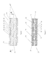
- Figure 1 is a side elevation view of a rotary flexible shaft according to the invention, disposed within a casing, showing the casing in cross-section.
- Figure 2 is a side cross-sectional view of the shaft shown in Figure 1 according to a first embodiment of the invention, taken along the cutting plane A--A of Figure 1 .
- Figure 3 is a side cross-sectional view of the shaft shown in Figure 1 according to a second and preferred embodiment of the invention, taken along the cutting plane A--A of Figure 1 .
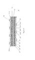
- Figure 4 is a side elevation view of a rotary flexible shaft according to a third embodiment of the invention, disposed within a casing, showing the casing in cross-section.
- Figure 5 is a side cross-sectional view of the shaft shown in Figure 4 , taken along the cutting plane B--B of Figure 4 .
- the flexible shaft 10 is disposed within a cylindrical casing 11 having an inner wall 12 which closely surrounds the shaft.
- the shaft 10 has a core which is a single wire 12 as shown in Figure 2 ; while the shafts 13 and 14 shown in Figures 3 and 5 respectively each have a core comprising one wire layer 16 helically wound on a single central wire 15.
- the flexible shafts shown in Figures 2 and 3 have the external appearance shown in Figure 1
- the shaft shown in Figure 5 has the external appearance shown in Figure 4 .
- Each of the layers shown in Figures 1 through 5 consists of five wires.
- Each of the outer layers has four wires of circular cross-section and one flat wire which has a thickness substantially less than the diameter or thickness (these terms are used interchangeably here) of the circular wires.
- the outer layer of the shaft 10 has wires 21 through 25 helically wound on the core 12 in a first winding direction.
- Wire 21 is flat and has a thickness substantially less than the thickness (or diameter) of wires 22 through 25.
- a strand 26 of resilient compressible material such as flocked yarn is helically wound on the flat wire 21.
- the strand 26 has a diameter or thickness which is such that the strand protrudes beyond the outer surfaces of the wires 22 through 25, so that when the shaft 10 is disposed within the closely surrounding casing 11 and rotated within the casing, the strand 26 engages the inner wall 27 of the casing 11 and acts as a buffer to reduce contact between the outer layer of the shaft 10 and the casing inner wall; thus reducing noise.
- flocked yarn is preferred for the strand 26
- other resilient compressible materials such as soft monofilament material, or suitable forms of flexible resilient thermoplastic or thermosetting polymers.
- Flexible shafts are frequently formed with square ends to facilitate engagement between driving and driven members.
- the ends may be formed, for example, by swaging the shaft. Since the strand 26 is flexible and resilient, it will extend beyond the adjacent wires of the shaft outer layer at the ends after the swaging process, so that the strand at the shaft ends will provide reduction of noise due to movement between the shaft ends and mating recesses at the driving and driven ends when the shaft is rotated.
- the strand 26 may be formed by applying a suitable polymer in liquid form to the flat wire 21, and causing the polymer to cure.
- the width of the flat wire 21 is preferably slightly greater than the diameter of the adjacent wires and is selected to accommodate a strand 26 of desired size.
- the wire 21 acts as a spacer to insure uniform width of the space into which the strand is wound, and prevent undesirable shifting of wires in the outer layer which could otherwise occur if the wire 26 were to be omitted as taught by the aforementioned Eichenberger patent.
- the wire 21 may be extruded from a wire of circular cross-section, and for that purpose the wire preferably comprises a ductile material such as aluminum or copper. It may alternatively comprise steel, metal alloys, or a flexible plastic.
- the flexible shaft 13 ( Figure 3 ) is similar to the shaft 10, except that the core is not a single wire, but has a layer of wires 27 through 31 helically wound thereon, in a winding circular wires 22a, 23a, 24a, 25a, and flat wire 26a.
- the flat wire may be coated with a layer 32 of glue and a relatively large number of fibers 33 may be embedded in the glue using an electrostatic or other suitable process, so that the fibers protrude beyond the outer layer of the flexible shaft 14 to engage the inner wall of the casing 27 of the casing 11, to reduce noise in the same manner as the strand 26.
- wire may have a different shape, such as a concave upper surface for helping to receive and contain the glue in the embodiment shown in Figures 4 and 5 .
Landscapes
- Engineering & Computer Science (AREA)
- General Engineering & Computer Science (AREA)
- Health & Medical Sciences (AREA)
- Oral & Maxillofacial Surgery (AREA)
- Mechanical Engineering (AREA)
- Flexible Shafts (AREA)
Abstract
Description
- This application claims the benefit of
U.S. Provisional Application Serial No. 61/803,125 filed March 19, 2013 - The present invention relates to a rotating flexible shaft having tips or ends adapted to engage mating elements of driving or driven members; and more particularly to a flexible shaft having a wire wound outer layer.
- Rotary shafts for transmitting torque typically have square ends adapted to engage square recesses of mating driving and driven parts. Rotary flexible shafts commonly used to transmit torque from a motor to adjust a seat in a motor vehicle, for example, are disposed within cylindrical casings which eliminate buckling and isolate the rotating shaft from contact with adjacent structures.
- For "perceived quality" reasons, especially in consumer products, it is desirable to reduce noise due to rattle between the rotating shaft and the surrounding casing and/or the driving and driven components to the greatest extent practicable. For this purpose it is known to replace one of the wires in the outer wire wound layer of the flexible shaft with a cord, strand or thread of relatively soft material (compared to that of the casing) such as flocked yarn. The terms cord, strand and thread are used interchangeably herein.
- Eichenberger et al. European Patent
EP 1286065 discloses such a shaft, in which a wire of the outer layer is omitted to leave a gap, and flocked yarn having a diameter greater than that of the outer layer wires is wound into the gap; so that the yarn contacts the inner wall of the casing and isolates the wires from the wall, thus reducing noise when the shaft is rotated. - However, omission of an outer layer wire in Eichenberger et al. reduces the consistency of pitch of the outer layer and allows the gap in which the yarn is disposed to vary in width as the shaft is manufactured and processed, thus diminishing the consistency of the protrusion of the flocked yarn. Omitting a wire also reduces the useful life of the shaft.
- In
U.S. Patent 3,389,579 to Werner et al. entitled Shaft Guided In A Protection Tube, noise isolation between a flexible shaft and a surrounding protection tube is provided by adhering short elastic fibers to the outer surface of the shaft or the inner surface of the protection tube, to form a brush-like layer between the shaft and tube. - In
U.S. Patent 4,411,168 to Yoshifuji entitled Inner Cable, noise due to contact between a push-pull wire wound flexible cable and a surrounding conduit is reduced by winding a hollow elastic member on the cable core between wire teeth also wound on the core, the elastic member having a greater diameter than the teeth so that only the elastic member contacts the inner surface of the conduit, thus reducing noise when the cable is moved longitudinally. - In
U.S. Patent 4,849,038 to Burghardt entitled Method For Depositing An Interlining On A Pitched Cable For Reducing Friction And Noise, a filament flocked with abrasion resistant material is wound or deposited on a wire wound flexible shaft, interleaved with the wire of the outer layer of the shaft. - In
U.S. Patent 7,717,795 to Mellor , a deformable polytetrafluoroethylene sheath is applied over the ends of a flexible shaft to reduce noise and vibration due to friction and relative movement between the shaft ends and mating recesses. - Accordingly, an object of the present invention is to provide a rotary flexible shaft that exhibits low rotational noise when coupled between driving and driven members and disposed within a surrounding casing.
- A flexible shaft which serves to transmit torque has a core and at least one layer thereon. The outer layer has a number of wires including at least one wire having a noncircular cross-section, the wires being helically wound in a first winding direction. The maximum thickness of said wire of noncircular cross-section is substantially less than the maximum diameter of the other outer layer wires. A strand of resilient compressible material is wound on the wire of noncircular cross-section and protrudes above the adjacent portions of the outer layer.
- By engaging the inner wall of a surrounding casing, and/or of the driving and driven components, the protruding parts of the resilient compressible material reduce noise when the shaft is rotated.
-
Figure 1 is a side elevation view of a rotary flexible shaft according to the invention, disposed within a casing, showing the casing in cross-section. -
Figure 2 is a side cross-sectional view of the shaft shown inFigure 1 according to a first embodiment of the invention, taken along the cutting plane A--A ofFigure 1 . -
Figure 3 is a side cross-sectional view of the shaft shown inFigure 1 according to a second and preferred embodiment of the invention, taken along the cutting plane A--A ofFigure 1 . -
Figure 4 is a side elevation view of a rotary flexible shaft according to a third embodiment of the invention, disposed within a casing, showing the casing in cross-section. -
Figure 5 is a side cross-sectional view of the shaft shown inFigure 4 , taken along the cutting plane B--B ofFigure 4 . - As shown in
Figures 1 and 2 , theflexible shaft 10 is disposed within acylindrical casing 11 having aninner wall 12 which closely surrounds the shaft. - The
shaft 10 has a core which is asingle wire 12 as shown inFigure 2 ; while theshafts Figures 3 and5 respectively each have a core comprising onewire layer 16 helically wound on a singlecentral wire 15. - The flexible shafts shown in
Figures 2 and3 have the external appearance shown inFigure 1 , while the shaft shown inFigure 5 has the external appearance shown inFigure 4 . - Each of the layers shown in
Figures 1 through 5 consists of five wires. Each of the outer layers has four wires of circular cross-section and one flat wire which has a thickness substantially less than the diameter or thickness (these terms are used interchangeably here) of the circular wires. - As shown in
Figures 1 and 2 , the outer layer of theshaft 10 haswires 21 through 25 helically wound on thecore 12 in a first winding direction.Wire 21 is flat and has a thickness substantially less than the thickness (or diameter) ofwires 22 through 25. - A
strand 26 of resilient compressible material such as flocked yarn is helically wound on theflat wire 21. - The
strand 26 has a diameter or thickness which is such that the strand protrudes beyond the outer surfaces of thewires 22 through 25, so that when theshaft 10 is disposed within the closely surroundingcasing 11 and rotated within the casing, thestrand 26 engages theinner wall 27 of thecasing 11 and acts as a buffer to reduce contact between the outer layer of theshaft 10 and the casing inner wall; thus reducing noise. - While flocked yarn is preferred for the
strand 26, other resilient compressible materials may be used, such as soft monofilament material, or suitable forms of flexible resilient thermoplastic or thermosetting polymers. - Flexible shafts are frequently formed with square ends to facilitate engagement between driving and driven members. The ends may be formed, for example, by swaging the shaft. Since the
strand 26 is flexible and resilient, it will extend beyond the adjacent wires of the shaft outer layer at the ends after the swaging process, so that the strand at the shaft ends will provide reduction of noise due to movement between the shaft ends and mating recesses at the driving and driven ends when the shaft is rotated. - Instead of flocked yarn, the
strand 26 may be formed by applying a suitable polymer in liquid form to theflat wire 21, and causing the polymer to cure. - The width of the
flat wire 21 is preferably slightly greater than the diameter of the adjacent wires and is selected to accommodate astrand 26 of desired size. Thus thewire 21 acts as a spacer to insure uniform width of the space into which the strand is wound, and prevent undesirable shifting of wires in the outer layer which could otherwise occur if thewire 26 were to be omitted as taught by the aforementioned Eichenberger patent. - The
wire 21 may be extruded from a wire of circular cross-section, and for that purpose the wire preferably comprises a ductile material such as aluminum or copper. It may alternatively comprise steel, metal alloys, or a flexible plastic. - The flexible shaft 13 (
Figure 3 ) is similar to theshaft 10, except that the core is not a single wire, but has a layer ofwires 27 through 31 helically wound thereon, in a windingcircular wires flat wire 26a. - Instead of a strand 26 (
Figures 1 and 2 ) or 26a (Figure 3 ), as shown inFigure 4 and5 the flat wire may be coated with alayer 32 of glue and a relatively large number offibers 33 may be embedded in the glue using an electrostatic or other suitable process, so that the fibers protrude beyond the outer layer of theflexible shaft 14 to engage the inner wall of thecasing 27 of thecasing 11, to reduce noise in the same manner as thestrand 26. - While a flat wire is preferred for receiving the
strand 26 or glue andfibers Figures 4 and5 .
Claims (11)
- A flexible shaft for transmitting torque, said shaft having a core and at least one layer thereon,
the outer layer comprising a plurality of wires including at least one wire having a noncircular cross-section, said wires being helically wound in a first winding direction,
the maximum thickness of said wire of noncircular cross-section being substantially less than the maximum diameter of said outer layer wires of circular cross-section; and
a strand of resilient compressible material wound on said wire of noncircular cross-section,
said strand protruding above the adjacent portions of said outer layer. - The flexible shaft according to Claim 1, wherein said core comprises an inner layer of wires helically wound in a second winding direction opposite to the first winding direction.
- The flexible shaft according to Claim 1 or 2, wherein said wire of non-circular cross-section is substantially flat.
- The flexible shaft according to Claim 1, 2 or 3, wherein said strand comprises flocked yarn.
- The flexible shaft according to Claim 1 or 2, wherein said strand comprises a thermoplastic or thermosetting material.
- A flexible shaft for transmitting torque, said shaft having a core and at least one layer thereon,
the outer layer comprising a plurality of wires having a circular cross-section and at least one wire having a noncircular cross-section, said wires being helically wound in a first winding direction,
the maximum thickness of said wire of noncircular cross-section being substantially less than the maximum diameter of said outer layer wires of circular cross-section;
a layer of glue on said wire of noncircular cross-section; and
a multiplicity of resilient fibers adhering to said glue layer, said fibers protruding above the adjacent portions of said outer layer. - A flexible shaft for transmitting torque, said shaft having a core and at least one layer thereon,
the outer layer comprising a plurality of wires having a circular cross-section and at least one wire having a noncircular cross-section, said wires being helically wound in a first winding direction,
said wire of noncircular cross-section being substantially flat with a thickness substantially less than the maximum diameter of said outer layer wires of circular cross-section; and
a strand of flocked yarn wound on said wire of noncircular cross-section,
said strand protruding above the adjacent portions of said outer layer. - In combination,
a flexible shaft for transmitting torque, said shaft having a core and at least one layer thereon,
the outer layer comprising a plurality of wires, at least one wire having a noncircular cross-section, said wires being helically wound in a first winding direction,
the maximum thickness of said wire of noncircular cross-section being less than the maximum diameter of said outer layer wires of circular cross-section; and
a strand of resilient compressible material wound on said wire of noncircular cross-section,
said strand protruding above the adjacent portions of said outer layer;
and
a casing surrounding said shaft and having an inner wall in contact with at least a portion of the outer surface of said strand;
whereby said strand engages said inner wall to reduce rattle between the inner wall and the outer layer of the shaft, thus reducing noise when the shaft is rotated within the casing. - The combination according to Claim 8, wherein said wire of non-circular cross-section is substantially flat.
- The flexible shaft according to Claim 8 or 9, wherein said strand comprises flocked yarn.
- The flexible shaft according to Claim 8, 9 or 10, wherein said strand comprises a thermoplastic or thermosetting material.
Applications Claiming Priority (2)
| Application Number | Priority Date | Filing Date | Title |
|---|---|---|---|
| US201361803125P | 2013-03-19 | 2013-03-19 | |
| US13/873,314 US8827820B1 (en) | 2013-03-19 | 2013-04-30 | Flexible shaft with interference fit capability |
Publications (2)
| Publication Number | Publication Date |
|---|---|
| EP2781771A1 true EP2781771A1 (en) | 2014-09-24 |
| EP2781771B1 EP2781771B1 (en) | 2016-01-20 |
Family
ID=48698900
Family Applications (1)
| Application Number | Title | Priority Date | Filing Date |
|---|---|---|---|
| EP13172343.9A Active EP2781771B1 (en) | 2013-03-19 | 2013-06-17 | Flexible shaft with interference fit capability |
Country Status (2)
| Country | Link |
|---|---|
| US (1) | US8827820B1 (en) |
| EP (1) | EP2781771B1 (en) |
Cited By (2)
| Publication number | Priority date | Publication date | Assignee | Title |
|---|---|---|---|---|
| EP2927518A1 (en) * | 2014-04-03 | 2015-10-07 | Daedong System Co., Ltd. | Flocked driving cable and manufacturing method thereof |
| EP3348849A1 (en) | 2017-01-11 | 2018-07-18 | Gemo G. Moritz GmbH & Co. KG | Flexible shaft with noise-reducing wrapping and method for the production of a flexible shaft with noise-reducing wrapping |
Families Citing this family (3)
| Publication number | Priority date | Publication date | Assignee | Title |
|---|---|---|---|---|
| DE102014201320B4 (en) * | 2013-11-04 | 2020-06-18 | Brose Fahrzeugteile SE & Co. Kommanditgesellschaft, Coburg | Drive shaft assembly with a flexible, flocked drive shaft, process for its manufacture and rail adjustment system |
| KR101864010B1 (en) * | 2016-05-20 | 2018-06-07 | 주식회사 대동시스템 | Automotive power transmission cables |
| US10533601B2 (en) * | 2017-03-10 | 2020-01-14 | S.S. White Technologies, Inc. | Casing for a flexible shaft assembly of a vehicle power seat adjuster |
Citations (10)
| Publication number | Priority date | Publication date | Assignee | Title |
|---|---|---|---|---|
| US2211790A (en) * | 1938-07-02 | 1940-08-20 | M R C Ltd | Flexible power transmission member |
| US3389579A (en) | 1965-04-02 | 1968-06-25 | Vdo Schindling | Shaft guided in a protection tube |
| US3391531A (en) * | 1965-03-22 | 1968-07-09 | Macwhyte Company | Strand and rope |
| DE3104819A1 (en) * | 1981-02-11 | 1982-08-19 | Nippon Cable System Inc., Takarazuka, Hyogo | Actuating cable or the like |
| US4411168A (en) | 1981-02-18 | 1983-10-25 | Nippon Cable System, Inc. | Inner cable |
| DE3513093A1 (en) * | 1985-04-12 | 1986-10-23 | Gesellschaft für Steuerungstechnik mbH & Co, 6332 Ehringshausen | Process for applying a friction-reducing and noise-reducing intermediate layer to a pitch cable |
| US4849038A (en) | 1986-04-26 | 1989-07-18 | Gesellschaft Fuer Steuerungstechnik Gmbh & Co. | Method for depositing an interlining on a pitched cable for reducing friction and noise |
| EP1286065A1 (en) | 2001-08-20 | 2003-02-26 | Otto Suhner AG | Flexible shaft with noise reducing component |
| US7717795B2 (en) | 2006-06-30 | 2010-05-18 | S.S. White Technologies Inc. | Low vibration noise flexible shaft |
| US20130000470A1 (en) * | 2009-09-25 | 2013-01-03 | Hi-Lex Corporation | Toothed cable, cable device provided with a toothed cable, and system for moving a moving object, said system provided with a toothed cable |
Family Cites Families (1)
| Publication number | Priority date | Publication date | Assignee | Title |
|---|---|---|---|---|
| US5913944A (en) * | 1997-08-14 | 1999-06-22 | Triumph Controls, Inc. | Cable assembly with telescoping core terminal |
-
2013
- 2013-04-30 US US13/873,314 patent/US8827820B1/en active Active
- 2013-06-17 EP EP13172343.9A patent/EP2781771B1/en active Active
Patent Citations (10)
| Publication number | Priority date | Publication date | Assignee | Title |
|---|---|---|---|---|
| US2211790A (en) * | 1938-07-02 | 1940-08-20 | M R C Ltd | Flexible power transmission member |
| US3391531A (en) * | 1965-03-22 | 1968-07-09 | Macwhyte Company | Strand and rope |
| US3389579A (en) | 1965-04-02 | 1968-06-25 | Vdo Schindling | Shaft guided in a protection tube |
| DE3104819A1 (en) * | 1981-02-11 | 1982-08-19 | Nippon Cable System Inc., Takarazuka, Hyogo | Actuating cable or the like |
| US4411168A (en) | 1981-02-18 | 1983-10-25 | Nippon Cable System, Inc. | Inner cable |
| DE3513093A1 (en) * | 1985-04-12 | 1986-10-23 | Gesellschaft für Steuerungstechnik mbH & Co, 6332 Ehringshausen | Process for applying a friction-reducing and noise-reducing intermediate layer to a pitch cable |
| US4849038A (en) | 1986-04-26 | 1989-07-18 | Gesellschaft Fuer Steuerungstechnik Gmbh & Co. | Method for depositing an interlining on a pitched cable for reducing friction and noise |
| EP1286065A1 (en) | 2001-08-20 | 2003-02-26 | Otto Suhner AG | Flexible shaft with noise reducing component |
| US7717795B2 (en) | 2006-06-30 | 2010-05-18 | S.S. White Technologies Inc. | Low vibration noise flexible shaft |
| US20130000470A1 (en) * | 2009-09-25 | 2013-01-03 | Hi-Lex Corporation | Toothed cable, cable device provided with a toothed cable, and system for moving a moving object, said system provided with a toothed cable |
Cited By (3)
| Publication number | Priority date | Publication date | Assignee | Title |
|---|---|---|---|---|
| EP2927518A1 (en) * | 2014-04-03 | 2015-10-07 | Daedong System Co., Ltd. | Flocked driving cable and manufacturing method thereof |
| EP3348849A1 (en) | 2017-01-11 | 2018-07-18 | Gemo G. Moritz GmbH & Co. KG | Flexible shaft with noise-reducing wrapping and method for the production of a flexible shaft with noise-reducing wrapping |
| WO2018130259A1 (en) | 2017-01-11 | 2018-07-19 | Gemo G. Moritz Gmbh & Co. Kg | Flexible shaft with noise-reducing wrapping, and method for producing a flexible shaft with a noise-reducing wrapping |
Also Published As
| Publication number | Publication date |
|---|---|
| US8827820B1 (en) | 2014-09-09 |
| EP2781771B1 (en) | 2016-01-20 |
Similar Documents
| Publication | Publication Date | Title |
|---|---|---|
| EP2781771B1 (en) | Flexible shaft with interference fit capability | |
| CN107407322B (en) | Drive cables for actuating vehicle components | |
| US6209415B1 (en) | Push-pull control cable | |
| JP3226893B2 (en) | Soundproof toothed cable | |
| EP2093438A1 (en) | Bowden cable and casing therefore | |
| EP1553226A3 (en) | Method for fabricating a cable and cable produced by this method | |
| KR101846108B1 (en) | Wire | |
| JP5091475B2 (en) | Soundproof toothed cable | |
| US8382596B2 (en) | Low noise flexible shaft | |
| JP4347441B2 (en) | Control cable inset | |
| US8162761B2 (en) | Low interface noise rotary shaft tips | |
| JPH06294460A (en) | Flocked type inner cable | |
| CN108474407B (en) | Drive cables and drive units for vehicle components | |
| US10801160B2 (en) | Draw tape for cables or similar flexible elements | |
| US8425334B2 (en) | Low noise and vibration flexible shaft | |
| JP4621322B2 (en) | Inner cable and control cable using it | |
| JP4439828B2 (en) | Control cable | |
| US2438053A (en) | Motion transmitting device | |
| DE102012104888B4 (en) | Control cable and cable window regulator | |
| WO2018199332A1 (en) | Control cable | |
| JP2002020984A (en) | Method for producing noiseproof cable having teeth | |
| JP2017040335A (en) | Control cable | |
| JP2847054B2 (en) | Ground anchor method | |
| JP6149256B2 (en) | Control cable | |
| EP2733370A1 (en) | Sheath for a remote control cable |
Legal Events
| Date | Code | Title | Description |
|---|---|---|---|
| PUAI | Public reference made under article 153(3) epc to a published international application that has entered the european phase |
Free format text: ORIGINAL CODE: 0009012 |
|
| 17P | Request for examination filed |
Effective date: 20130617 |
|
| AK | Designated contracting states |
Kind code of ref document: A1 Designated state(s): AL AT BE BG CH CY CZ DE DK EE ES FI FR GB GR HR HU IE IS IT LI LT LU LV MC MK MT NL NO PL PT RO RS SE SI SK SM TR |
|
| AX | Request for extension of the european patent |
Extension state: BA ME |
|
| R17P | Request for examination filed (corrected) |
Effective date: 20150309 |
|
| RBV | Designated contracting states (corrected) |
Designated state(s): AL AT BE BG CH CY CZ DE DK EE ES FI FR GB GR HR HU IE IS IT LI LT LU LV MC MK MT NL NO PL PT RO RS SE SI SK SM TR |
|
| GRAP | Despatch of communication of intention to grant a patent |
Free format text: ORIGINAL CODE: EPIDOSNIGR1 |
|
| RIC1 | Information provided on ipc code assigned before grant |
Ipc: F16C 1/06 20060101AFI20150630BHEP |
|
| INTG | Intention to grant announced |
Effective date: 20150717 |
|
| GRAS | Grant fee paid |
Free format text: ORIGINAL CODE: EPIDOSNIGR3 |
|
| GRAA | (expected) grant |
Free format text: ORIGINAL CODE: 0009210 |
|
| AK | Designated contracting states |
Kind code of ref document: B1 Designated state(s): AL AT BE BG CH CY CZ DE DK EE ES FI FR GB GR HR HU IE IS IT LI LT LU LV MC MK MT NL NO PL PT RO RS SE SI SK SM TR |
|
| REG | Reference to a national code |
Ref country code: GB Ref legal event code: FG4D |
|
| REG | Reference to a national code |
Ref country code: CH Ref legal event code: EP |
|
| REG | Reference to a national code |
Ref country code: IE Ref legal event code: FG4D |
|
| REG | Reference to a national code |
Ref country code: AT Ref legal event code: REF Ref document number: 771873 Country of ref document: AT Kind code of ref document: T Effective date: 20160215 |
|
| REG | Reference to a national code |
Ref country code: DE Ref legal event code: R096 Ref document number: 602013004698 Country of ref document: DE |
|
| REG | Reference to a national code |
Ref country code: FR Ref legal event code: PLFP Year of fee payment: 4 |
|
| REG | Reference to a national code |
Ref country code: LT Ref legal event code: MG4D Ref country code: NL Ref legal event code: MP Effective date: 20160120 |
|
| REG | Reference to a national code |
Ref country code: AT Ref legal event code: MK05 Ref document number: 771873 Country of ref document: AT Kind code of ref document: T Effective date: 20160120 |
|
| PG25 | Lapsed in a contracting state [announced via postgrant information from national office to epo] |
Ref country code: NL Free format text: LAPSE BECAUSE OF FAILURE TO SUBMIT A TRANSLATION OF THE DESCRIPTION OR TO PAY THE FEE WITHIN THE PRESCRIBED TIME-LIMIT Effective date: 20160120 |
|
| PG25 | Lapsed in a contracting state [announced via postgrant information from national office to epo] |
Ref country code: HR Free format text: LAPSE BECAUSE OF FAILURE TO SUBMIT A TRANSLATION OF THE DESCRIPTION OR TO PAY THE FEE WITHIN THE PRESCRIBED TIME-LIMIT Effective date: 20160120 Ref country code: GR Free format text: LAPSE BECAUSE OF FAILURE TO SUBMIT A TRANSLATION OF THE DESCRIPTION OR TO PAY THE FEE WITHIN THE PRESCRIBED TIME-LIMIT Effective date: 20160421 Ref country code: ES Free format text: LAPSE BECAUSE OF FAILURE TO SUBMIT A TRANSLATION OF THE DESCRIPTION OR TO PAY THE FEE WITHIN THE PRESCRIBED TIME-LIMIT Effective date: 20160120 Ref country code: FI Free format text: LAPSE BECAUSE OF FAILURE TO SUBMIT A TRANSLATION OF THE DESCRIPTION OR TO PAY THE FEE WITHIN THE PRESCRIBED TIME-LIMIT Effective date: 20160120 Ref country code: NO Free format text: LAPSE BECAUSE OF FAILURE TO SUBMIT A TRANSLATION OF THE DESCRIPTION OR TO PAY THE FEE WITHIN THE PRESCRIBED TIME-LIMIT Effective date: 20160420 Ref country code: IT Free format text: LAPSE BECAUSE OF FAILURE TO SUBMIT A TRANSLATION OF THE DESCRIPTION OR TO PAY THE FEE WITHIN THE PRESCRIBED TIME-LIMIT Effective date: 20160120 |
|
| PG25 | Lapsed in a contracting state [announced via postgrant information from national office to epo] |
Ref country code: AT Free format text: LAPSE BECAUSE OF FAILURE TO SUBMIT A TRANSLATION OF THE DESCRIPTION OR TO PAY THE FEE WITHIN THE PRESCRIBED TIME-LIMIT Effective date: 20160120 Ref country code: SE Free format text: LAPSE BECAUSE OF FAILURE TO SUBMIT A TRANSLATION OF THE DESCRIPTION OR TO PAY THE FEE WITHIN THE PRESCRIBED TIME-LIMIT Effective date: 20160120 Ref country code: LT Free format text: LAPSE BECAUSE OF FAILURE TO SUBMIT A TRANSLATION OF THE DESCRIPTION OR TO PAY THE FEE WITHIN THE PRESCRIBED TIME-LIMIT Effective date: 20160120 Ref country code: PT Free format text: LAPSE BECAUSE OF FAILURE TO SUBMIT A TRANSLATION OF THE DESCRIPTION OR TO PAY THE FEE WITHIN THE PRESCRIBED TIME-LIMIT Effective date: 20160520 Ref country code: PL Free format text: LAPSE BECAUSE OF FAILURE TO SUBMIT A TRANSLATION OF THE DESCRIPTION OR TO PAY THE FEE WITHIN THE PRESCRIBED TIME-LIMIT Effective date: 20160120 Ref country code: RS Free format text: LAPSE BECAUSE OF FAILURE TO SUBMIT A TRANSLATION OF THE DESCRIPTION OR TO PAY THE FEE WITHIN THE PRESCRIBED TIME-LIMIT Effective date: 20160120 Ref country code: IS Free format text: LAPSE BECAUSE OF FAILURE TO SUBMIT A TRANSLATION OF THE DESCRIPTION OR TO PAY THE FEE WITHIN THE PRESCRIBED TIME-LIMIT Effective date: 20160520 Ref country code: LV Free format text: LAPSE BECAUSE OF FAILURE TO SUBMIT A TRANSLATION OF THE DESCRIPTION OR TO PAY THE FEE WITHIN THE PRESCRIBED TIME-LIMIT Effective date: 20160120 |
|
| REG | Reference to a national code |
Ref country code: DE Ref legal event code: R097 Ref document number: 602013004698 Country of ref document: DE |
|
| PG25 | Lapsed in a contracting state [announced via postgrant information from national office to epo] |
Ref country code: DK Free format text: LAPSE BECAUSE OF FAILURE TO SUBMIT A TRANSLATION OF THE DESCRIPTION OR TO PAY THE FEE WITHIN THE PRESCRIBED TIME-LIMIT Effective date: 20160120 Ref country code: EE Free format text: LAPSE BECAUSE OF FAILURE TO SUBMIT A TRANSLATION OF THE DESCRIPTION OR TO PAY THE FEE WITHIN THE PRESCRIBED TIME-LIMIT Effective date: 20160120 |
|
| PLBE | No opposition filed within time limit |
Free format text: ORIGINAL CODE: 0009261 |
|
| STAA | Information on the status of an ep patent application or granted ep patent |
Free format text: STATUS: NO OPPOSITION FILED WITHIN TIME LIMIT |
|
| PG25 | Lapsed in a contracting state [announced via postgrant information from national office to epo] |
Ref country code: RO Free format text: LAPSE BECAUSE OF FAILURE TO SUBMIT A TRANSLATION OF THE DESCRIPTION OR TO PAY THE FEE WITHIN THE PRESCRIBED TIME-LIMIT Effective date: 20160120 Ref country code: SM Free format text: LAPSE BECAUSE OF FAILURE TO SUBMIT A TRANSLATION OF THE DESCRIPTION OR TO PAY THE FEE WITHIN THE PRESCRIBED TIME-LIMIT Effective date: 20160120 Ref country code: CZ Free format text: LAPSE BECAUSE OF FAILURE TO SUBMIT A TRANSLATION OF THE DESCRIPTION OR TO PAY THE FEE WITHIN THE PRESCRIBED TIME-LIMIT Effective date: 20160120 Ref country code: SK Free format text: LAPSE BECAUSE OF FAILURE TO SUBMIT A TRANSLATION OF THE DESCRIPTION OR TO PAY THE FEE WITHIN THE PRESCRIBED TIME-LIMIT Effective date: 20160120 |
|
| 26N | No opposition filed |
Effective date: 20161021 |
|
| PG25 | Lapsed in a contracting state [announced via postgrant information from national office to epo] |
Ref country code: BE Free format text: LAPSE BECAUSE OF FAILURE TO SUBMIT A TRANSLATION OF THE DESCRIPTION OR TO PAY THE FEE WITHIN THE PRESCRIBED TIME-LIMIT Effective date: 20160120 |
|
| PG25 | Lapsed in a contracting state [announced via postgrant information from national office to epo] |
Ref country code: MC Free format text: LAPSE BECAUSE OF FAILURE TO SUBMIT A TRANSLATION OF THE DESCRIPTION OR TO PAY THE FEE WITHIN THE PRESCRIBED TIME-LIMIT Effective date: 20160120 |
|
| REG | Reference to a national code |
Ref country code: CH Ref legal event code: PL |
|
| PG25 | Lapsed in a contracting state [announced via postgrant information from national office to epo] |
Ref country code: SI Free format text: LAPSE BECAUSE OF FAILURE TO SUBMIT A TRANSLATION OF THE DESCRIPTION OR TO PAY THE FEE WITHIN THE PRESCRIBED TIME-LIMIT Effective date: 20160120 Ref country code: BG Free format text: LAPSE BECAUSE OF FAILURE TO SUBMIT A TRANSLATION OF THE DESCRIPTION OR TO PAY THE FEE WITHIN THE PRESCRIBED TIME-LIMIT Effective date: 20160420 |
|
| REG | Reference to a national code |
Ref country code: IE Ref legal event code: MM4A |
|
| PG25 | Lapsed in a contracting state [announced via postgrant information from national office to epo] |
Ref country code: CH Free format text: LAPSE BECAUSE OF NON-PAYMENT OF DUE FEES Effective date: 20160630 Ref country code: LI Free format text: LAPSE BECAUSE OF NON-PAYMENT OF DUE FEES Effective date: 20160630 |
|
| REG | Reference to a national code |
Ref country code: FR Ref legal event code: PLFP Year of fee payment: 5 |
|
| PG25 | Lapsed in a contracting state [announced via postgrant information from national office to epo] |
Ref country code: IE Free format text: LAPSE BECAUSE OF NON-PAYMENT OF DUE FEES Effective date: 20160617 |
|
| REG | Reference to a national code |
Ref country code: FR Ref legal event code: PLFP Year of fee payment: 6 |
|
| PG25 | Lapsed in a contracting state [announced via postgrant information from national office to epo] |
Ref country code: HU Free format text: LAPSE BECAUSE OF FAILURE TO SUBMIT A TRANSLATION OF THE DESCRIPTION OR TO PAY THE FEE WITHIN THE PRESCRIBED TIME-LIMIT; INVALID AB INITIO Effective date: 20130617 |
|
| PG25 | Lapsed in a contracting state [announced via postgrant information from national office to epo] |
Ref country code: MT Free format text: LAPSE BECAUSE OF NON-PAYMENT OF DUE FEES Effective date: 20160630 Ref country code: MK Free format text: LAPSE BECAUSE OF FAILURE TO SUBMIT A TRANSLATION OF THE DESCRIPTION OR TO PAY THE FEE WITHIN THE PRESCRIBED TIME-LIMIT Effective date: 20160120 Ref country code: CY Free format text: LAPSE BECAUSE OF FAILURE TO SUBMIT A TRANSLATION OF THE DESCRIPTION OR TO PAY THE FEE WITHIN THE PRESCRIBED TIME-LIMIT Effective date: 20160120 Ref country code: LU Free format text: LAPSE BECAUSE OF NON-PAYMENT OF DUE FEES Effective date: 20160617 |
|
| PG25 | Lapsed in a contracting state [announced via postgrant information from national office to epo] |
Ref country code: AL Free format text: LAPSE BECAUSE OF FAILURE TO SUBMIT A TRANSLATION OF THE DESCRIPTION OR TO PAY THE FEE WITHIN THE PRESCRIBED TIME-LIMIT Effective date: 20160120 Ref country code: TR Free format text: LAPSE BECAUSE OF FAILURE TO SUBMIT A TRANSLATION OF THE DESCRIPTION OR TO PAY THE FEE WITHIN THE PRESCRIBED TIME-LIMIT Effective date: 20160120 |
|
| REG | Reference to a national code |
Ref country code: DE Ref legal event code: R082 Ref document number: 602013004698 Country of ref document: DE Representative=s name: D YOUNG & CO LLP, DE |
|
| PGFP | Annual fee paid to national office [announced via postgrant information from national office to epo] |
Ref country code: DE Payment date: 20250610 Year of fee payment: 13 |
|
| PGFP | Annual fee paid to national office [announced via postgrant information from national office to epo] |
Ref country code: GB Payment date: 20250616 Year of fee payment: 13 |
|
| PGFP | Annual fee paid to national office [announced via postgrant information from national office to epo] |
Ref country code: FR Payment date: 20250611 Year of fee payment: 13 |