EP2786472B1 - Elektrische maschine - Google Patents
Elektrische maschine Download PDFInfo
- Publication number
- EP2786472B1 EP2786472B1 EP12805975.5A EP12805975A EP2786472B1 EP 2786472 B1 EP2786472 B1 EP 2786472B1 EP 12805975 A EP12805975 A EP 12805975A EP 2786472 B1 EP2786472 B1 EP 2786472B1
- Authority
- EP
- European Patent Office
- Prior art keywords
- electrical machine
- machine
- winding
- cryostat
- stator
- Prior art date
- Legal status (The legal status is an assumption and is not a legal conclusion. Google has not performed a legal analysis and makes no representation as to the accuracy of the status listed.)
- Active
Links
Images

Classifications
-
- H—ELECTRICITY
- H02—GENERATION; CONVERSION OR DISTRIBUTION OF ELECTRIC POWER
- H02K—DYNAMO-ELECTRIC MACHINES
- H02K55/00—Dynamo-electric machines having windings operating at cryogenic temperatures
- H02K55/02—Dynamo-electric machines having windings operating at cryogenic temperatures of the synchronous type
-
- Y—GENERAL TAGGING OF NEW TECHNOLOGICAL DEVELOPMENTS; GENERAL TAGGING OF CROSS-SECTIONAL TECHNOLOGIES SPANNING OVER SEVERAL SECTIONS OF THE IPC; TECHNICAL SUBJECTS COVERED BY FORMER USPC CROSS-REFERENCE ART COLLECTIONS [XRACs] AND DIGESTS
- Y02—TECHNOLOGIES OR APPLICATIONS FOR MITIGATION OR ADAPTATION AGAINST CLIMATE CHANGE
- Y02E—REDUCTION OF GREENHOUSE GAS [GHG] EMISSIONS, RELATED TO ENERGY GENERATION, TRANSMISSION OR DISTRIBUTION
- Y02E40/00—Technologies for an efficient electrical power generation, transmission or distribution
- Y02E40/60—Superconducting electric elements or equipment; Power systems integrating superconducting elements or equipment
Definitions
- the invention relates to an electric machine with a stator, with a rotor and with a plurality of machine coils.
- Such electrical machines in which the rotor rotates relative to a fixed stator, are used in various embodiments in a variety of applications both as motors and as generators.
- the electric machines can be operated with three-phase current and designed as an asynchronous or synchronous machine.
- the electric machine may necessarily have a considerable weight and volume, whereby the manufacture and assembly of the electric machine is difficult. If necessary, foundations or the like specially adapted to the respective electrical machine must be provided. This results in significant costs.
- the object of the invention is therefore to further develop known electrical machines in such a way that the power density is increased, the volume and the weight of the electric machine are reduced and the dynamic operating behavior is improved.
- the EP 1 959 548 A1 discloses an electric machine having cooling means adapted to cool a superconducting material at least to below a transition temperature, the windings being of superconducting material and being operatively connected to the cooling means.
- Superconducting materials are materials whose electrical resistance falls abruptly to zero when a material-specific transition temperature falls below zero. If the windings of the machine coils cooled to below the critical temperature are subjected to an alternating current, for example, only a small energy loss occurs, which is only very slight in comparison to an ohmic resistance. As a result, strong electromagnetic fields can be generated even with comparatively small machines, which considerably increases the power density of the electrical machines and enables high dynamics.
- the electric machine with a superconducting winding can, for example, with a three-phase alternating current operate. But it is also possible to operate the electric machine with a higher-phase alternating current.
- the electric machine can be operated both in a lower speed range and at the same time high torque as well as in a so-called field weakening range up to high speeds at a constant power.
- a superconducting material for example, high-temperature superconductors in question, the critical temperature can be reached even at a temperature of minus 140 degrees Celsius.
- superconducting materials can be used, for example in tape or wire form.
- Suitable superconducting materials include the compositions YBCO (YBCO coated conductor) or BSCCO, which can have an extremely high current density at sufficiently low temperatures.
- the machine coils can be arranged both on or in the rotor and on or in the stator.
- the stator can be arranged outside (as external rotor) or inside the rotor (as internal rotor)
- the machine coils are arranged on the stator, that the stator and the machine coils are arranged inside a stator cryostat and that the stator cryostat is in operative connection with the cooling device.
- the entire stator including the stator arranged machine coils cooled below the respective transition temperature of the windings. Different cooling principles can be used.
- the stator cryostat may be a bath cryostat in which the stator and the machine coils to be cooled are surrounded by a cryogenic liquid, for example liquid nitrogen.
- a cryogenic liquid for example liquid nitrogen.
- the stator cryostat it is also possible for the stator cryostat to be a refrigerator cryostat in which the cooling takes place by means of a so-called cryo-cooler.
- the elements required for magnetic flux guidance for example iron cores arranged within the winding, are also cooled.
- the rotor and its storage facilities can be in the warm area and only the stator can be cooled with windings of the machine coils arranged thereon.
- At least one machine coil is arranged within a winding cryostat and the winding cryostat is in operative connection with the cooling device. In this way, not the entire stator space must be cooled, but only a much smaller area around the machine spools.
- the cooling power required for cooling can be further reduced in that the winding cryostat is configured torus-shaped or race-track-shaped. Within the torus formed by the winding cryostat a spool core can be arranged. Expediently, the winding cryostat has a recess adapted to a winding of the machine coil for receiving the coil core. In this way, only the windings are cooled to the transition temperature, while all other elements, such as the coil cores required for magnetic flux guidance, are operated at room temperature.
- machine coils arranged within a winding cryostat and connected to the rotor can be cooled in this way.
- the rotor is operated at room temperature.
- the winding cryostat has two coolant connections, which are arranged, for example, on the opposite sides of the winding cryostat. These coolant connections can be connected to the cooling device, for example, with suitable pipes or hose lines. A suitable cryogenic fluid, for example liquid or gaseous nitrogen, can then be passed into the winding cryostat via these lines.
- a suitable cryogenic fluid for example liquid or gaseous nitrogen
- the electric machine has two parallel to each other with respect to a rotational axis of the electric machine coaxially arranged connection rings with adapted to the coolant connections coolant connection receptacles.
- the winding cryostat can be easily arranged with the respective coolant connections in the adapted thereto coolant connection receptacles of the connection rings.
- the invention provides that the winding cryostat is arranged within a thermal insulator.
- the thermal insulator may be a radiation shielding foil or another mirror surface.
- the thermal insulator has areas in which a vacuum can be generated. In this case, it is necessary for the winding cryostat to be vacuum-tightly separated from the thermal insulator. It is also possible that there is a vacuum in the entire thermal insulator.
- the thermal insulator consists of a material which has a high electrical resistance.
- the thermal insulator of a Plastic with correspondingly high electrical resistance.
- the winding cryostat can be filled with a cryogenic fluid.
- the cryogenic fluid may be a cryogenic liquid or cooled gas.
- a cryogenic liquid for example, liquid nitrogen, liquid neon, liquid hydrogen or liquid helium come into question.
- the cooling device has a cryocooler.
- the cryocooler is a suitable heat exchanger that removes heat absorbed by the cryovluid.
- the cooling device and the respective cryostats expediently form a closed circuit, which is formed by corresponding tube or pipe connections arranged between the cooling device and the cryostat.
- a corresponding coolant pump may be provided for circulating the Kryofluids within the closed cooling circuit.
- the cooling device has a control device which is adapted to adaptively adapt a cooling capacity to a machine load.
- the control device may comprise, for example, a control valve arranged in the cooling circuit, a temperature sensor in the return of the cooling circuit and a digital-electronic calculation device, wherein the control device is adapted to a regulation of the measured return temperature with the control valve.
- the electric machine has a controllable or controllable supply device for controlling or regulating a machine speed.
- the controllable or controllable supply device may be, for example, a frequency converter.
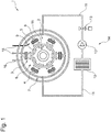
- FIG. 1 shows a schematic representation of a known electric machine 1 with a stator 2, on which a plurality of machine coils 3 are arranged. Windings 4 of the machine coils 3 are made of a superconducting material.
- the machine coils 3 have coil cores 5 and are arranged inside a stator cryostat 6.
- the stator cryostat 6 is disposed within a thermal insulator 7 which is formed by two cylindrical and coaxially arranged vacuum tubes 8, 9 and not shown vacuum tube covers.
- the stator cryostat 6 is connected to a cryocooler 10 via pipelines 11.
- a cryogenic fluid is circulated within this cooling circuit formed by the stator cryostat 6, the cryocooler 10, the pipelines 11, a coolant pump 12 and a control device 13 with the aid of the coolant pump 12 within the cooling circuit. With the control device 13, the coolant flow rate is controlled.
- the cryocooler 10, the coolant pump 12 and the control device 13 form a cooling device 14.
- the windings 4 of the machine coils 3 are supplied via electrical connections 16 via a frequency converter, not shown, with a three-phase current.
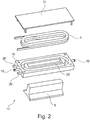
- FIG. 2 schematically an exploded view of a winding cryostat 17 according to the invention with a thermally insulated cryostat housing 18 is shown.
- a superconducting winding 4 can be arranged within the cryostat housing 18.
- the superconducting winding shown here is a "double pancake winding". Of course it could also be a "single pancake coil” used.
- the winding cryostat 17 can be closed with a winding cryostat cover 21 which can be connected to the cryostat housing 18. On the cryostat housing 18 coolant connections 19 and power connection elements 20 are arranged.
- the winding cryostat 17 has a recess 22 adapted to the spool core 5.
- FIG. 3 shows a schematic exploded view of a terminal ring 23 and a winding cryostat 17, in which a coil core 5 can be arranged.
- the coolant connection 19 of the winding cryostat 17 can be connected to a coolant connection receptacle 24 of the connection ring 23 adapted to the coolant connection 19.
- the power connection elements 20 of the winding cryostat 17 are connected to power receiving elements 25 connectable to the connection ring 23.
- the connection ring 23 has electrical connections 16 and a connection 26 that can be connected to a coolant circuit (not shown).
- connection ring 23 and one winding cryostat 17 are shown in this illustration. On the presentation of other elements of the associated electric machine has been omitted.
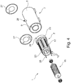
- FIG. 4 shows a schematically illustrated exploded view of an electrical machine 1.
- the electric machine 1 has a stator 2 and a rotor 15.
- the stator 2 has two connection rings 23 arranged parallel to one another and coaxial to a rotation axis of the electric machine 1. Winding cryostats 17 are arranged on the connection rings 23.
- the stator 2 can be arranged inside a thermal insulator 7.
- the thermal insulator 7 consists of a first vacuum tube 8 and a coaxial within the first vacuum tube 7 arranged second vacuum tube 9.
- the first vacuum tube 8 and the second vacuum tube 9 can be closed vacuum-tight with annular vacuum tube covers 27. With the aid of a vacuum connection 28, a vacuum can be generated within the thermal insulator 7 formed by the first vacuum tube 8, the second vacuum tube 9 and the vacuum tube covers 27 via a vacuum pump (not shown).
Landscapes
- Engineering & Computer Science (AREA)
- Power Engineering (AREA)
- Superconductive Dynamoelectric Machines (AREA)
- Motor Or Generator Cooling System (AREA)
Description
- Die Erfindung betrifft eine elektrische Maschine mit einem Stator, mit einem Rotor und mit mehreren Maschinenspulen.
- Solche elektrischen Maschinen, bei denen der Rotor relativ zu einem feststehenden Stator eine Drehbewegung ausführt, werden in unterschiedlichsten Ausführungsformen in einer Vielzahl von Anwendungsgebieten sowohl als Motoren als auch als Generatoren eingesetzt. Beispielsweise können die elektrischen Maschinen mit Drehstrom betrieben und als Asynchron- oder Synchronmaschine ausgeführt sein.
- In Abhängigkeit von der vorgesehenen Leistung der elektrischen Maschine kann die elektrische Maschine notwendigerweise ein erhebliches Gewicht und Volumen aufweisen, wodurch die Herstellung und Montage der elektrischen Maschine erschwert wird. Gegebenenfalls müssen speziell an die jeweilige elektrische Maschine angepasste Fundamente oder dergleichen bereitgestellt werden. Dies hat erhebliche Kosten zur Folge.
- Für einige Anwendungen werden zudem elektrische Maschinen mit sehr kurzen Anregelzeiten bzw. einem schnellen, dynamischen Betriebsverhalten benötigt. Beispielsweise werden solche elektrischen Maschinen als Belastungseinrichtungen für hochdynamische Motorenprüfstände eingesetzt. Herkömmliche elektrische Maschinen können die steigenden Anforderungen in diesem Bereich häufig nicht oder nur unzureichend erfüllen. Aufgabe der Erfindung ist es daher, bekannte elektrische Maschinen dahingehend weiter zu entwickeln, dass die Leistungsdichte erhöht, das Volumen und das Gewicht der elektrischen Maschine reduziert und das dynamische Betriebsverhalten verbessert wird.
- Diese Aufgabe wird erfindungsgemäß durch die Merkmale des Anspruchs 1 gelöst.
- Die
EP 1 959 548 A1 offenbart eine elektrische Maschine, die eine Kühleinrichtung aufweist, die dazu geeignet ist, ein supraleitendes Material mindestens bis unter eine Sprungtemperatur abzukühlen, wobei die Wicklungen aus supraleitender Material bestehen und mit der Kühleinrichtung in Wirkverbindung stehen. Supraleitende Materialien sind Materialien, deren elektrischer Widerstand bei Unterschreiten einer materialspezifischen Sprungtemperatur sprunghaft auf Null abfällt. Werden die bis unter die Sprungtemperatur abgekühlten Wicklungen der Maschinenspulen beispielsweise mit einem Wechselstrom beaufschlagt, tritt nur ein geringer Energieverlust ein, der gegenüber einem Ohm'schen Widerstand nur sehr gering ist. Dadurch können auch mit vergleichsweise kleinen Maschinen starke elektromagnetische Felder erzeugt werden, wodurch die Leistungsdichte der elektrischen Maschinen erheblich steigt und eine hohe Dynamik ermöglicht wird. - Die elektrische Maschine mit einer supraleitenden Wicklung kann beispielsweise mit einem dreiphasigen Wechselstrom betrieben werden. Es ist aber auch möglich, die elektrische Maschine mit einem höherphasigen Wechselstrom zu betreiben. Die elektrische Maschine kann dabei sowohl in einem niedrigeren Drehzahlbereich und gleichzeitig hohem Drehmoment als auch in einem sogenannten Feldschwächungsbereich bis zu hohen Geschwindigkeiten bei einer konstanten Leistung betrieben werden.
- Als supraleitendes Material kommen beispielsweise Hochtemperatursupraleiter in Frage, deren Sprungtemperatur bereits bei einer Temperatur von minus 140 Grad Celsius erreicht sein kann. Für die Wicklung der Maschinenspulen können supraleitende Materialien beispielsweise in Band- oder Drahtform eingesetzt werden. Als supraleitende Materialien kommen unter anderem die Zusammensetzungen YBCO (YBCO coated conductor) oder BSCCO in Frage, die bei ausreichend tiefen Temperaturen eine außerordentlich hohe Stromdichte aufweisen können.
- Die Maschinenspulen können sowohl am oder im Rotor als auch am oder im Stator angeordnet sein. Der Stator kann außerhalb (als Außenläufer) oder innerhalb des Rotors (als Innenläufer) angeordnet sein
Um an dem Stator angeordnete Maschinenspulen auf die Sprungtemperatur abkühlen zu können ist es bekannt, dass die Maschinenspulen an dem Stator angeordnet sind, dass der Stator und die Maschinenspulen innerhalb eines Statorkryostaten angeordnet sind und dass der Statorkryostat mit der Kühleinrichtung in Wirkverbindung steht. Innerhalb des Statorkryostaten wird also der gesamte Stator mitsamt den an dem Stator angeordneten Maschinenspulen unter die jeweilige Sprungtemperatur der Wicklungen abgekühlt. Dabei können verschiedene Kühlprinzipien eingesetzt werden. Beispielsweise kann es sich bei dem Statorkryostaten um einen Badkryostaten handeln, bei denen der Stator und die zu kühlenden Maschinenspulen von einer Kryoflüssigkeit, beispielsweise von flüssigem Stickstoff umgeben sind. Es ist aber auch möglich, dass es sich bei dem Statorkryostaten um einen Refrigeratorkryostaten handelt, bei dem die Kühlung durch einen sogenannten Cryo-Cooler erfolgt. - Bei dieser Anordnung werden neben den auf Sprungtemperatur abzukühlenden Wicklungen der Maschinenspulen auch die zur magnetischen Flussführung benötigten Elemente, beispielsweise innerhalb der Wicklung angeordnete Eisenkerne gekühlt. Der Rotor und dessen Lagereinrichtungen können im warmen Bereich liegen und nur der Stator mit daran angeordneten Wicklungen der Maschinenspulen gekühlt werden.
- Um die benötigte Kühlleistung zur Abkühlung der Wicklungen unter die Sprungtemperatur zu reduzieren, ist erfindungsgemäß vorgesehen, dass mindestens eine Maschinenspule innerhalb eines Wicklungskryostaten angeordnet ist und der Wicklungskryostat mit der Kühleinrichtung in Wirkverbindung steht. Auf diese Weise muss nicht der gesamte Statorraum abgekühlt werden, sondern lediglich ein wesentlich kleinerer Bereich um die Maschinenspulen.
- Die zur Abkühlung benötigte Kühlleistung kann dadurch weiter reduziert werden, dass der Wicklungskryostat torusförmig oder race-track-förmig ausgestaltet ist. Innerhalb des von dem Wicklungskryostaten gebildeten Torus kann ein Spulenkern angeordnet werden. Zweckmäßigerweise weist der Wicklungskryostat eine an eine Wicklung der Maschinenspule angepasste Ausnehmung zur Aufnahme des Spulenkerns auf. Auf diese Weise werden lediglich die Wicklungen bis zur Sprungtemperatur abgekühlt, während alle weiteren Elemente, beispielsweise die zur magnetischen Flussführung benötigten Spulenkerne, bei Raumtemperatur betrieben werden.
- Ebenso können innerhalb eines Wicklungskryostaten angeordnete und mit dem Rotor verbundene Maschinenspulen auf diese Weise gekühlt werden. Dabei wird der Rotor bei Raumtemperatur betrieben.
- Um Kühlleistung von der Kühleinrichtung auf den Wicklungskryostaten übertragen zu können, ist erfindungsgemäß vorgesehen, dass der Wicklungskryostat zwei Kühlmittelanschlüsse aufweist, die beispielsweise an den gegenüber liegenden Seiten des Wicklungskryostaten angeordnet sind. Diese Kühlmittelanschlüsse können beispielsweise mit geeigneten Rohrleitungen oder Schlauchleitungen mit der Kühleinrichtung verbunden sein. Über diese Leitungen kann dann ein geeignetes Kryofluid, beispielsweise flüssiger oder gasförmiger Stickstoff, in den Wicklungskryostat geleitet werden.
- Zur einfacheren Versorgung der mehreren Wicklungskryostaten mit dem Kryofluid ist erfindungsgemäß vorgesehen, dass die elektrische Maschine zwei parallel zueinander bezüglich einer Rotationsachse der elektrischen Maschine koaxial angeordnete Anschlussringe mit an die Kühlmittelanschlüsse angepassten Kühlmittelanschlussaufnahmen aufweist. Die Wicklungskryostaten können einfach mit den jeweiligen Kühlmittelanschlüssen in den daran angepassten Kühlmittelanschlussaufnahmen der Anschlussringe angeordnet werden.
- Um die zur Kühlung benötigte Kühlleistung zu verringern ist erfindungsgemäß vorgesehen, dass der Wicklungskryostat innerhalb eines thermischen Isolators angeordnet ist. Beispielsweise kann es sich bei dem thermischen Isolator um eine Strahlung abschirmende Folie oder um eine andere Spiegelfläche handeln.
- Es ist darüber hinaus möglich und erfindungsgemäß vorgesehen, dass der thermische Isolator Bereiche aufweist, in denen ein Vakuum erzeugbar ist. In diesem Fall ist es erforderlich, dass der Wicklungskryostat vakuumdicht von dem thermischen Isolator getrennt sind. Es ist auch möglich, dass in dem gesamten thermischen Isolator ein Vakuum herrscht.
- Um die in dem thermischen Isolator durch das von den Maschinenspulen hervorgerufene Wechselfeld erzeugten Wirbelströme zu verringern, ist erfindungsgemäß vorgesehen, dass der thermische Isolator aus einem Material besteht, das einen hohen elektrischen Widerstand aufweist. Beispielsweise kann der thermische Isolator aus einem Kunststoff mit entsprechend hohem elektrischen Widerstand bestehen.
- Bei einer besonders vorteilhaften Ausgestaltung des Erfindungsgedankens ist vorgesehen, dass der Wicklungskryostat mit einem kryogenen Fluid befüllbar ist. Bei dem kryogenen Fluid kann es sich um eine kryogene Flüssigkeit oder um gekühltes Gas handeln. Als kryogene Flüssigkeit kommen beispielsweise flüssiger Stickstoff, flüssiges Neon, flüssiger Wasserstoff oder flüssiges Helium in Frage.
- Erfindungsgemäß ist vorgesehen, dass die Kühleinrichtung einen Kryokühler aufweist. Bei dem Kryokühler handelt es sich um einen geeigneten Wärmetauscher, der von dem Kryofluid aufgenommene Wärme abführt. In diesem Fall stellen die Kühleinrichtung und die jeweiligen Kryostaten zweckmäßigerweise einen geschlossenen Kreislauf dar, der von entsprechenden zwischen der Kühleinrichtung und der Kryostaten angeordnete Schlauch- oder Rohrverbindungen gebildet wird. Zur Umwälzung des Kryofluids innerhalb des geschlossenen Kühlkreislaufs kann eine entsprechende Kühlmittelpumpe vorgesehen sein.
- Es ist aber auch möglich, die Kühleinrichtung und die Kryostaten in einem offenen Kühlkreislauf zu betreiben. Vorteilhafterweise ist vorgesehen, dass die Kühleinrichtung eine Regeleinrichtung aufweist, die dazu geeignet ist, eine Kühlleistung an eine Maschinenlast adaptiv anzupassen. Auf diese Weise können beispielsweise auch kurzfristig auftretende höhere Maschinenlasten von der elektrischen Maschine aufgenommen werden, ohne dass die Temperatur der Wicklungen die Sprungtemperatur erreicht und die Wicklungen die supraleitende Eigenschaft verlieren. Die Regeleinrichtung kann beispielsweise ein in dem Kühlkreislauf angeordnetes Regelventil, einen Temperatursensor im Rücklauf des Kühlkreislaufs und eine digital-elektronische Berechnungseinrichtung aufweisen, wobei die Regeleinrichtung an eine Regelung der gemessenen Rücklauftemperatur mit dem Regelventil angepasst ist.
- Bei einer besonders vorteilhaften Ausgestaltung der Erfindung ist vorgesehen, dass die elektrische Maschine eine steuerbare oder regelbare Versorgungseinrichtung zur Steuerung oder Regelung einer Maschinendrehzahl aufweist. Bei der steuerbaren oder regelbaren Versorgungseinrichtung kann es sich beispielsweise um einen Frequenzumrichter handeln.
- Weitere vorteilhafte Ausgestaltungen des Erfindungsgedankens werden in der Zeichnung anhand von exemplarischen Ausführungsbeispielen erläutert. Es zeigt:
-
Figur 1 eine schematische Darstellung einer bekannten elektrischen Maschine mit innerhalb eines Statorkryostaten angeordneten supraleitenden Wicklungen, -
Figur 2 eine schematisch dargestellte Explosionszeichnung eines Wicklungskryostaten, -
Figur 3 eine schematisch dargestellte Explosionszeichnung eines Wicklungskryostaten und eines Anschlussrings, -
Figur 4 eine schematisch dargestellte Explosionszeichnung einer innerhalb eines thermischen Isolators angeordneten Stators, an dem mehrere Wicklungskryostaten angeordnete sind. -
Figur 1 zeigt eine schematische Darstellung einer bekannten elektrischen Maschine 1 mit einem Stator 2, an dem mehrere Maschinenspulen 3 angeordnet sind. Wicklungen 4 der Maschinenspulen 3 bestehen aus einem supraleitenden Material. Die Maschinenspulen 3 weisen Spulenkerne 5 auf und sind innerhalb eines Statorkryostaten 6 angeordnet. Der Statorkryostat 6 ist innerhalb eines thermischen Isolators 7 angeordnet, der von zwei zylindrischen und koaxial zueinander angeordneten Vakuumröhren 8, 9 und nicht dargestellten Vakuumröhrendeckeln gebildet ist. - In der Zeichnung ist zur Veranschaulichung jeweils nur eine Maschinenspule 3, eine Wicklung 4 und ein Spulenkern 5 mit einem zugeordneten Bezugszeichen versehen.
- Der Statorkryostat 6 ist mit einem Kryokühler 10 über Rohrleitungen 11 verbunden. Ein kryogenes Fluid wird innerhalb dieses von dem Statorkryostaten 6, dem Kryokühler 10, den Rohrleitungen 11, einer Kühlmittelpumpe 12 und einer Regeleinrichtung 13 gebildeten Kühlkreislauf mit Hilfe der Kühlmittelpumpe 12 innerhalb des Kühlkreislaufs umgewälzt. Mit der Regeleinrichtung 13 wird die Kühlmitteldurchflussmenge gesteuert. Der Kryokühler 10, die Kühlmittelpumpe 12 und die Regeleinrichtung 13 bilden eine Kühleinrichtung 14.
- Im Inneren der elektrischen Maschine 1 befindet sich ein Rotor 15. Die Wicklungen 4 der Maschinenspulen 3 werden über elektrische Anschlüsse 16 über einen nicht dargestellten Frequenzumrichter mit einem Drehstrom versorgt.
- In
Figur 2 ist schematisch eine Explosionszeichnung eines erfindungsgemäßen Wicklungskryostaten 17 mit einem thermisch isolierten Kryostatgehäuse 18 dargestellt. - Innerhalb des Kryostatgehäuses 18 kann eine supraleitende Wicklung 4 angeordnet werden. Bei der hier dargestellten supraleitenden Wicklung handelt es sich um eine "Double Pancake Wicklung". Es könnte natürlich auch eine "Single pancake Spule" verwendet werden.
- Der Wicklungskryostat 17 kann mit einem mit dem Kryostatgehäuse 18 verbindbaren Wicklungskryostatdeckel 21 verschlossen werden. An dem Kryostatgehäuse 18 sind Kühlmittelanschlüsse 19 und Stromanschlusselemente 20 angeordnet. Der Wicklungskryostat 17 weist eine an den Spulenkern 5 angepasste Ausnehmung 22 auf.
-
Figur 3 zeigt eine schematisch dargestellte Explosionszeichnung eines Anschlussrings 23 und eines Wicklungskryostaten 17, in dem ein Spulenkern 5 angeordnet werden kann. Der Kühlmittelanschluss 19 des Wicklungskryostaten 17 kann mit einer an den Kühlmittelanschluss 19 angepassten Kühlmittelanschlussaufnahme 24 des Anschlussrings 23 verbunden werden. Die Stromanschlusselemente 20 des Wicklungskryostaten 17 sind mit Stromaufnahmeelementen 25 des Anschlussrings 23 verbindbar. Der Anschlussring 23 weist elektrische Anschlüsse 16 und einen mit einem nicht dargestellten Kühlmittelkreislauf verbindbaren Anschluss 26 auf. - Der Übersichtlichkeit halber ist in dieser Darstellung lediglich ein Anschlussring 23 und ein Wicklungskryostat 17 dargestellt. Auf die Darstellung weiterer Elemente der zugehörigen elektrischen Maschine wurde verzichtet.
-
Figur 4 zeigt eine schematisch dargestellte Explosionszeichnung einer elektrischen Maschine 1. Die elektrische Maschine 1 weist einen Stator 2 und einen Rotor 15 auf. Der Stator 2 weist zwei parallel zueinander und koaxial zu einer Rotationsachse der elektrischen Maschine 1 angeordnete Anschlussringe 23 auf. An den Anschlussringen 23 sind Wicklungskryostaten 17 angeordnet. Der Stator 2 kann innerhalb eines thermischen Isolators 7 angeordnet werden. Der thermische Isolator 7 besteht aus einer ersten Vakuumröhre 8 und einem innerhalb der ersten Vakuumröhre 7 koaxial angeordneten zweiten Vakuumröhre 9. Die erste Vakuumröhre 8 und die zweite Vakuumröhre 9 können mit ringförmigen Vakuumröhrendeckeln 27 vakuumdicht verschlossen werden. Mit Hilfe eine Vakuumanschlusses 28 kann über eine nicht dargestellte Vakuumpumpe ein Vakuum innerhalb des von der ersten Vakuumröhre 8, der zweiten Vakuumröhre 9 und den Vakuumröhrendeckeln 27 gebildeten thermischen Isolators 7 erzeugt werden. - Bei einer anderen konstruktiven Umsetzung könnte in einem Luftspalt der elektrischen Maschine 1 nur eine Vakuumröhre erforderlich sein, die nicht gesondert gekühlt werden muss und deren Temperatur der Umgebungstemperatur, bzw. der Raumtemperatur entsprechen kann.
Claims (12)
- Elektrische Maschine (1) mit einem Stator (2), mit einem Rotor (15) und mit mehreren Maschinenspulen (3), wobei die Maschinenspulen (3) am oder im Stator (2) angeordnet sind, wobei die elektrische Maschine (1) eine Kühleinrichtung (14) aufweist, die dazu geeignet ist, ein supraleitendes Material mindestens bis unter eine Sprungtemperatur abzukühlen, wobei eine Wicklung (4) mindestens einer Maschinenspule (3) aus dem supraleitenden Material besteht und wobei die Wicklung (4) mit der Kühleinrichtung (14) in Wirkverbindung steht, dadurch gekennzeichnet, dass die mindestens eine Maschinenspule (3) innerhalb eines Wicklungskryostaten (17) angeordnet ist und der Wicklungskryostat (17) mit der Kühleinrichtung (14) in Wirkverbindung steht, sodass nicht ein gesamter Statorraum abgekühlt werden muss, sondern lediglich ein wesentlich kleinerer Bereich um die Maschinenspulen (3).
- Elektrische Maschine (1) gemäß Anspruch 1, dadurch gekennzeichnet, dass der Wicklungskryostat (17) torusförmig ausgestaltet ist.
- Elektrische Maschine (1) gemäß Anspruch 1 oder Anspruch 2, dadurch gekennzeichnet, dass der Wicklungskryostat (17) zwei Kühlmittelanschlüsse (19) aufweist.
- Elektrische Maschine (1) gemäß Anspruch 3, dadurch gekennzeichnet, dass der Wicklungskryostat (17) an gegenüberliegenden Seiten jeweils einen Kühlmittelanschluss (19) aufweist.
- Elektrische Maschine (1) gemäß Anspruch 3 oder Anspruch 4, dadurch gekennzeichnet, dass die elektrische Maschine (1) zwei parallel zueinander und bezüglich einer Rotationsachse der elektrischen Maschine (1) koaxial angeordnete Anschlussringe (23) mit an die Kühlmittelanschlüsse (19) angepassten Kühlmittelanschlussaufnahmen (24) aufweist.
- Elektrische Maschine (1) gemäß einem der Ansprüche 1 bis 5, dadurch gekennzeichnet, dass der Wicklungskryostat (17) innerhalb eines thermischen Isolators (7) angeordnet ist.
- Elektrische Maschine (1) gemäß Anspruch 6, dadurch gekennzeichnet, dass der thermischen Isolator (7) Bereiche aufweist, in denen ein Vakuum erzeugbar ist.
- Elektrische Maschine (1) gemäß Anspruch 6 oder Anspruch 7, dadurch gekennzeichnet, dass der thermische Isolator (7) aus einem Material besteht, das einen hohen elektrischen Widerstand aufweist.
- Elektrische Maschine (1) gemäß einem der Ansprüche 1 bis 8, dadurch gekennzeichnet, dass der Wicklungskryostat (17) mit einem kryogenen Fluid befüllbar ist.
- Elektrische Maschine (1) gemäß einem der voranstehenden Ansprüche, dadurch gekennzeichnet, dass die Kühleinrichtung (14) einen Kryokühler (10) aufweist.
- Elektrische Maschine (1) gemäß einem der voranstehenden Ansprüche, dadurch gekennzeichnet, dass die Kühleinrichtung (14) eine Regeleinrichtung (13) aufweist, die dazu geeignet ist, eine Kühlleistung an eine Maschinenlast adaptiv anzupassen.
- Elektrische Maschine (1) gemäß einem der voranstehenden Ansprüche, dadurch gekennzeichnet, dass die elektrische Maschine (1) eine steuerbare oder regelbare Versorgungseinrichtung zur Steuerung oder Regelung einer Maschinendrehzahl aufweist.
Applications Claiming Priority (2)
| Application Number | Priority Date | Filing Date | Title |
|---|---|---|---|
| DE102011056008A DE102011056008A1 (de) | 2011-12-02 | 2011-12-02 | Elektrische Maschine |
| PCT/EP2012/074205 WO2013079715A2 (de) | 2011-12-02 | 2012-12-03 | Elektrische maschine |
Publications (3)
| Publication Number | Publication Date |
|---|---|
| EP2786472A2 EP2786472A2 (de) | 2014-10-08 |
| EP2786472B1 true EP2786472B1 (de) | 2018-02-14 |
| EP2786472B2 EP2786472B2 (de) | 2021-09-01 |
Family
ID=47429760
Family Applications (1)
| Application Number | Title | Priority Date | Filing Date |
|---|---|---|---|
| EP12805975.5A Active EP2786472B2 (de) | 2011-12-02 | 2012-12-03 | Elektrische maschine |
Country Status (3)
| Country | Link |
|---|---|
| EP (1) | EP2786472B2 (de) |
| DE (1) | DE102011056008A1 (de) |
| WO (1) | WO2013079715A2 (de) |
Cited By (4)
| Publication number | Priority date | Publication date | Assignee | Title |
|---|---|---|---|---|
| EP3661035A1 (de) | 2018-11-27 | 2020-06-03 | Oswald Elektromotoren Gmbh | Supraleitende elektrische maschine |
| RU2735953C1 (ru) * | 2020-05-15 | 2020-11-11 | Российская Федерация, от имени которой выступает ФОНД ПЕРСПЕКТИВНЫХ ИССЛЕДОВАНИЙ | Способ криостатирования сверхпроводниковых обмоток бесколлекторного двигателя постоянного тока |
| LU102069B1 (de) | 2020-09-17 | 2022-03-18 | Oswald Elektromotoren Gmbh | Elektrische Maschine |
| CN116529985A (zh) * | 2020-10-27 | 2023-08-01 | 塔乌电机股份有限公司 | 用于使用冷却剂罐的电机的热管理的系统和方法 |
Families Citing this family (5)
| Publication number | Priority date | Publication date | Assignee | Title |
|---|---|---|---|---|
| DE102014114451A1 (de) | 2014-10-06 | 2016-04-07 | Oswald Elektromotoren Gmbh | Elektrische Maschine |
| JP6234914B2 (ja) * | 2014-11-17 | 2017-11-22 | ジャパンスーパーコンダクタテクノロジー株式会社 | 超電導回転電機のコイル |
| DE102015117296A1 (de) | 2015-10-09 | 2017-04-13 | Oswald Elektromotoren Gmbh | Elektrische Maschine |
| DE102018206564A1 (de) * | 2018-04-27 | 2019-10-31 | Siemens Aktiengesellschaft | Supraleitende elektrische Spuleneinrichtung sowie Rotor mit Spuleneinrichtung |
| RU199121U1 (ru) * | 2020-05-18 | 2020-08-17 | Российская Федерация, от имени которой выступает ФОНД ПЕРСПЕКТИВНЫХ ИССЛЕДОВАНИЙ | Высокомоментный электродвигатель на основе высокотемпературных сверхпроводников для прямого привода пропеллера или гребного винта |
Citations (10)
| Publication number | Priority date | Publication date | Assignee | Title |
|---|---|---|---|---|
| US4808864A (en) | 1986-09-25 | 1989-02-28 | Alsthom | Superconducting electric rotating machine and its thermal insulation |
| US5670838A (en) | 1991-06-05 | 1997-09-23 | Unique Mobility, Inc. | Electrical machines |
| EP1215801A2 (de) | 2000-12-14 | 2002-06-19 | Nissan Motor Co., Ltd. | Rotierende elektrische Maschine und ihr Herstellungsverfahren |
| WO2004073144A1 (en) | 2003-02-14 | 2004-08-26 | Toyota Jidosha Kabushiki Kaisha | Stator coil module, method of manufacturing the same, and electric rotating machine |
| EP1959548A1 (de) | 2007-02-15 | 2008-08-20 | General Electric Company | Verfahren und Vorrichtung für einen von einer Windturbine angetriebenen supraleitenden Generator |
| WO2009045038A2 (en) | 2007-10-02 | 2009-04-09 | Korea Electrotechnology Research Institute | Superconducting synchronous machine |
| WO2009068844A1 (en) | 2007-11-27 | 2009-06-04 | Rolls-Royce Plc | A superconducting electrical machine |
| DE102009054790A1 (de) | 2008-12-17 | 2010-07-01 | Toyota Jidosha Kabushiki Kaisha, Toyota-shi | Supraleitendes Gerät und zugehöriger Vakuumbehälter |
| JP2011142773A (ja) | 2010-01-08 | 2011-07-21 | Sumitomo Electric Ind Ltd | 超電導コイル機器、超電導機器、および超電導コイル機器の製造方法 |
| US20110285219A1 (en) | 2011-04-27 | 2011-11-24 | General Electric Company | Electrical Machine with Superconducting Armature Coils and Other Components |
Family Cites Families (3)
| Publication number | Priority date | Publication date | Assignee | Title |
|---|---|---|---|---|
| EP0805545B1 (de) * | 1996-05-01 | 2002-03-13 | General Electric Company | Zusammenstellung einer supraleitenden Feldwicklung für eine elektrische Maschine |
| DE19804208A1 (de) * | 1998-02-03 | 1999-08-05 | Frank Belitz | Elektrischer Turbogenerator |
| PL364023A1 (en) * | 2000-12-29 | 2004-11-29 | General Electric Company | Superconductive armature winding for an electrical machine |
-
2011
- 2011-12-02 DE DE102011056008A patent/DE102011056008A1/de not_active Withdrawn
-
2012
- 2012-12-03 WO PCT/EP2012/074205 patent/WO2013079715A2/de not_active Ceased
- 2012-12-03 EP EP12805975.5A patent/EP2786472B2/de active Active
Patent Citations (10)
| Publication number | Priority date | Publication date | Assignee | Title |
|---|---|---|---|---|
| US4808864A (en) | 1986-09-25 | 1989-02-28 | Alsthom | Superconducting electric rotating machine and its thermal insulation |
| US5670838A (en) | 1991-06-05 | 1997-09-23 | Unique Mobility, Inc. | Electrical machines |
| EP1215801A2 (de) | 2000-12-14 | 2002-06-19 | Nissan Motor Co., Ltd. | Rotierende elektrische Maschine und ihr Herstellungsverfahren |
| WO2004073144A1 (en) | 2003-02-14 | 2004-08-26 | Toyota Jidosha Kabushiki Kaisha | Stator coil module, method of manufacturing the same, and electric rotating machine |
| EP1959548A1 (de) | 2007-02-15 | 2008-08-20 | General Electric Company | Verfahren und Vorrichtung für einen von einer Windturbine angetriebenen supraleitenden Generator |
| WO2009045038A2 (en) | 2007-10-02 | 2009-04-09 | Korea Electrotechnology Research Institute | Superconducting synchronous machine |
| WO2009068844A1 (en) | 2007-11-27 | 2009-06-04 | Rolls-Royce Plc | A superconducting electrical machine |
| DE102009054790A1 (de) | 2008-12-17 | 2010-07-01 | Toyota Jidosha Kabushiki Kaisha, Toyota-shi | Supraleitendes Gerät und zugehöriger Vakuumbehälter |
| JP2011142773A (ja) | 2010-01-08 | 2011-07-21 | Sumitomo Electric Ind Ltd | 超電導コイル機器、超電導機器、および超電導コイル機器の製造方法 |
| US20110285219A1 (en) | 2011-04-27 | 2011-11-24 | General Electric Company | Electrical Machine with Superconducting Armature Coils and Other Components |
Non-Patent Citations (3)
| Title |
|---|
| A. CHEN ET AL.: "Design of the Cryogenic System for a 400 kW Experimental HTS Synchronous Motor", IEEE TRANSACTIONS ON APPLIED SUPERCONDUCTIVITY, vol. 20, no. 3, June 2010 (2010-06-01), pages 2062 - 2065, XP011303025 |
| L. LI ET AL.: "Magnetic Field Distribution around Superconducting Coils in Ferromagnet- ic Environment", IEEE TRANSACTIONS ON APPLIED SUPERCONDUCTIVITY, vol. 21, no. 3, June 2011 (2011-06-01), pages 1131 - 1135, XP011325238 |
| L. LI ET AL.: "Magnetic Field Distribution around Superconducting Coils in Ferromagnetic Environment", IEEE TRANSACTIONS ON APPLIED SUPERCONDUCTIVITY, vol. 21, no. 3, June 2011 (2011-06-01), pages 1131 - 1135, XP011325238 |
Cited By (6)
| Publication number | Priority date | Publication date | Assignee | Title |
|---|---|---|---|---|
| EP3661035A1 (de) | 2018-11-27 | 2020-06-03 | Oswald Elektromotoren Gmbh | Supraleitende elektrische maschine |
| RU2735953C1 (ru) * | 2020-05-15 | 2020-11-11 | Российская Федерация, от имени которой выступает ФОНД ПЕРСПЕКТИВНЫХ ИССЛЕДОВАНИЙ | Способ криостатирования сверхпроводниковых обмоток бесколлекторного двигателя постоянного тока |
| LU102069B1 (de) | 2020-09-17 | 2022-03-18 | Oswald Elektromotoren Gmbh | Elektrische Maschine |
| EP3972090A1 (de) | 2020-09-17 | 2022-03-23 | Oswald Elektromotoren Gmbh | Elektrische maschine |
| CN116529985A (zh) * | 2020-10-27 | 2023-08-01 | 塔乌电机股份有限公司 | 用于使用冷却剂罐的电机的热管理的系统和方法 |
| EP4238206A4 (de) * | 2020-10-27 | 2024-10-23 | Tau Motors, Inc. | System und verfahren zur wärmeverwaltung elektronischer maschinen mit kühlmitteldosen |
Also Published As
| Publication number | Publication date |
|---|---|
| EP2786472B2 (de) | 2021-09-01 |
| WO2013079715A3 (de) | 2013-10-10 |
| WO2013079715A2 (de) | 2013-06-06 |
| EP2786472A2 (de) | 2014-10-08 |
| DE102011056008A1 (de) | 2013-06-06 |
Similar Documents
| Publication | Publication Date | Title |
|---|---|---|
| EP2786472B2 (de) | Elektrische maschine | |
| EP1310035B1 (de) | Kühlungsvorrichtung der rotierenden, supraleitenden wicklung einer elektrischen maschine | |
| EP3491724B1 (de) | Rotor mit spulenanordnung und wicklungsträger | |
| EP1336236B1 (de) | Supraleitungseinrichtung mit einem thermisch an eine rotierende, supraleitende wicklung angekoppelten kaltkopf einer kälteeinheit | |
| EP3609057B1 (de) | Maschinenspule für eine elektrische maschine | |
| EP3769408B1 (de) | Supraleitende elektrische spuleneinrichtung sowie rotor mit spuleneinrichtung | |
| EP3350895A1 (de) | Energieübertragungsvorrichtung für ein fahrzeug | |
| DE102010001378A1 (de) | Supraleitende Vorrichtung | |
| EP3205005B1 (de) | Elektrische maschine | |
| DE102014224363A1 (de) | Vorrichtung der Supraleitungstechnik mitSpuleneinrichtungen und Kühlvorrichtung sowie damitausgestattetes Fahrzeug | |
| EP3360237B1 (de) | Elektrische maschine | |
| DE102018215917A1 (de) | Rotor mit Rotorwicklung für Betrieb im Dauerstrommodus | |
| WO2019197307A1 (de) | Rotor mit wicklungsträger und darin eingebettetem spulenelement | |
| Bruzek et al. | Superconducting DC cables to improve the efficiency of electricity transmission and distribution networks: An overview | |
| WO2015197477A1 (de) | Elektrische maschine | |
| EP3130068A1 (de) | Elektrische maschine für hohe drehzahlen | |
| WO2019091842A1 (de) | Rotor und maschine mit p-poliger rotorwicklung | |
| DE102009009127A1 (de) | Spule für ein supraleitendes Magnetlager | |
| EP3776827A1 (de) | Rotor und maschine mit zylinderförmigem tragkörper | |
| WO2024256434A1 (de) | Pumpe für eine kryogene flüssigkeit | |
| DE102018205170A1 (de) | Maschinenkomponente sowie elektrische Maschine mit supraleitendem Spulenelement | |
| DE102016221029A1 (de) | Elektrische Spuleneinrichtung zur Strombegrenzung mit Kryostat | |
| DE102013213242A1 (de) | Spuleneinrichtung mit Spule und Kühlvorrichtung sowie Verfahren zur Kühlung einer Spule |
Legal Events
| Date | Code | Title | Description |
|---|---|---|---|
| PUAI | Public reference made under article 153(3) epc to a published international application that has entered the european phase |
Free format text: ORIGINAL CODE: 0009012 |
|
| 17P | Request for examination filed |
Effective date: 20140701 |
|
| AK | Designated contracting states |
Kind code of ref document: A2 Designated state(s): AL AT BE BG CH CY CZ DE DK EE ES FI FR GB GR HR HU IE IS IT LI LT LU LV MC MK MT NL NO PL PT RO RS SE SI SK SM TR |
|
| DAX | Request for extension of the european patent (deleted) | ||
| GRAP | Despatch of communication of intention to grant a patent |
Free format text: ORIGINAL CODE: EPIDOSNIGR1 |
|
| STAA | Information on the status of an ep patent application or granted ep patent |
Free format text: STATUS: GRANT OF PATENT IS INTENDED |
|
| INTG | Intention to grant announced |
Effective date: 20171031 |
|
| GRAS | Grant fee paid |
Free format text: ORIGINAL CODE: EPIDOSNIGR3 |
|
| GRAA | (expected) grant |
Free format text: ORIGINAL CODE: 0009210 |
|
| STAA | Information on the status of an ep patent application or granted ep patent |
Free format text: STATUS: THE PATENT HAS BEEN GRANTED |
|
| AK | Designated contracting states |
Kind code of ref document: B1 Designated state(s): AL AT BE BG CH CY CZ DE DK EE ES FI FR GB GR HR HU IE IS IT LI LT LU LV MC MK MT NL NO PL PT RO RS SE SI SK SM TR |
|
| REG | Reference to a national code |
Ref country code: GB Ref legal event code: FG4D Free format text: NOT ENGLISH |
|
| REG | Reference to a national code |
Ref country code: CH Ref legal event code: EP |
|
| REG | Reference to a national code |
Ref country code: IE Ref legal event code: FG4D Free format text: LANGUAGE OF EP DOCUMENT: GERMAN |
|
| REG | Reference to a national code |
Ref country code: DE Ref legal event code: R096 Ref document number: 502012012160 Country of ref document: DE Ref country code: AT Ref legal event code: REF Ref document number: 970470 Country of ref document: AT Kind code of ref document: T Effective date: 20180315 |
|
| REG | Reference to a national code |
Ref country code: NL Ref legal event code: MP Effective date: 20180214 |
|
| PG25 | Lapsed in a contracting state [announced via postgrant information from national office to epo] |
Ref country code: FI Free format text: LAPSE BECAUSE OF FAILURE TO SUBMIT A TRANSLATION OF THE DESCRIPTION OR TO PAY THE FEE WITHIN THE PRESCRIBED TIME-LIMIT Effective date: 20180214 Ref country code: NO Free format text: LAPSE BECAUSE OF FAILURE TO SUBMIT A TRANSLATION OF THE DESCRIPTION OR TO PAY THE FEE WITHIN THE PRESCRIBED TIME-LIMIT Effective date: 20180514 Ref country code: CY Free format text: LAPSE BECAUSE OF FAILURE TO SUBMIT A TRANSLATION OF THE DESCRIPTION OR TO PAY THE FEE WITHIN THE PRESCRIBED TIME-LIMIT Effective date: 20180214 Ref country code: ES Free format text: LAPSE BECAUSE OF FAILURE TO SUBMIT A TRANSLATION OF THE DESCRIPTION OR TO PAY THE FEE WITHIN THE PRESCRIBED TIME-LIMIT Effective date: 20180214 Ref country code: NL Free format text: LAPSE BECAUSE OF FAILURE TO SUBMIT A TRANSLATION OF THE DESCRIPTION OR TO PAY THE FEE WITHIN THE PRESCRIBED TIME-LIMIT Effective date: 20180214 Ref country code: LT Free format text: LAPSE BECAUSE OF FAILURE TO SUBMIT A TRANSLATION OF THE DESCRIPTION OR TO PAY THE FEE WITHIN THE PRESCRIBED TIME-LIMIT Effective date: 20180214 Ref country code: HR Free format text: LAPSE BECAUSE OF FAILURE TO SUBMIT A TRANSLATION OF THE DESCRIPTION OR TO PAY THE FEE WITHIN THE PRESCRIBED TIME-LIMIT Effective date: 20180214 |
|
| PG25 | Lapsed in a contracting state [announced via postgrant information from national office to epo] |
Ref country code: RS Free format text: LAPSE BECAUSE OF FAILURE TO SUBMIT A TRANSLATION OF THE DESCRIPTION OR TO PAY THE FEE WITHIN THE PRESCRIBED TIME-LIMIT Effective date: 20180214 Ref country code: BG Free format text: LAPSE BECAUSE OF FAILURE TO SUBMIT A TRANSLATION OF THE DESCRIPTION OR TO PAY THE FEE WITHIN THE PRESCRIBED TIME-LIMIT Effective date: 20180514 Ref country code: SE Free format text: LAPSE BECAUSE OF FAILURE TO SUBMIT A TRANSLATION OF THE DESCRIPTION OR TO PAY THE FEE WITHIN THE PRESCRIBED TIME-LIMIT Effective date: 20180214 Ref country code: LV Free format text: LAPSE BECAUSE OF FAILURE TO SUBMIT A TRANSLATION OF THE DESCRIPTION OR TO PAY THE FEE WITHIN THE PRESCRIBED TIME-LIMIT Effective date: 20180214 Ref country code: GR Free format text: LAPSE BECAUSE OF FAILURE TO SUBMIT A TRANSLATION OF THE DESCRIPTION OR TO PAY THE FEE WITHIN THE PRESCRIBED TIME-LIMIT Effective date: 20180515 |
|
| PG25 | Lapsed in a contracting state [announced via postgrant information from national office to epo] |
Ref country code: MT Free format text: LAPSE BECAUSE OF FAILURE TO SUBMIT A TRANSLATION OF THE DESCRIPTION OR TO PAY THE FEE WITHIN THE PRESCRIBED TIME-LIMIT Effective date: 20180214 |
|
| REG | Reference to a national code |
Ref country code: DE Ref legal event code: R026 Ref document number: 502012012160 Country of ref document: DE |
|
| PG25 | Lapsed in a contracting state [announced via postgrant information from national office to epo] |
Ref country code: PL Free format text: LAPSE BECAUSE OF FAILURE TO SUBMIT A TRANSLATION OF THE DESCRIPTION OR TO PAY THE FEE WITHIN THE PRESCRIBED TIME-LIMIT Effective date: 20180214 Ref country code: EE Free format text: LAPSE BECAUSE OF FAILURE TO SUBMIT A TRANSLATION OF THE DESCRIPTION OR TO PAY THE FEE WITHIN THE PRESCRIBED TIME-LIMIT Effective date: 20180214 Ref country code: IT Free format text: LAPSE BECAUSE OF FAILURE TO SUBMIT A TRANSLATION OF THE DESCRIPTION OR TO PAY THE FEE WITHIN THE PRESCRIBED TIME-LIMIT Effective date: 20180214 Ref country code: RO Free format text: LAPSE BECAUSE OF FAILURE TO SUBMIT A TRANSLATION OF THE DESCRIPTION OR TO PAY THE FEE WITHIN THE PRESCRIBED TIME-LIMIT Effective date: 20180214 Ref country code: AL Free format text: LAPSE BECAUSE OF FAILURE TO SUBMIT A TRANSLATION OF THE DESCRIPTION OR TO PAY THE FEE WITHIN THE PRESCRIBED TIME-LIMIT Effective date: 20180214 |
|
| PLBI | Opposition filed |
Free format text: ORIGINAL CODE: 0009260 |
|
| PLBI | Opposition filed |
Free format text: ORIGINAL CODE: 0009260 |
|
| PLAX | Notice of opposition and request to file observation + time limit sent |
Free format text: ORIGINAL CODE: EPIDOSNOBS2 |
|
| PG25 | Lapsed in a contracting state [announced via postgrant information from national office to epo] |
Ref country code: CZ Free format text: LAPSE BECAUSE OF FAILURE TO SUBMIT A TRANSLATION OF THE DESCRIPTION OR TO PAY THE FEE WITHIN THE PRESCRIBED TIME-LIMIT Effective date: 20180214 Ref country code: SK Free format text: LAPSE BECAUSE OF FAILURE TO SUBMIT A TRANSLATION OF THE DESCRIPTION OR TO PAY THE FEE WITHIN THE PRESCRIBED TIME-LIMIT Effective date: 20180214 Ref country code: DK Free format text: LAPSE BECAUSE OF FAILURE TO SUBMIT A TRANSLATION OF THE DESCRIPTION OR TO PAY THE FEE WITHIN THE PRESCRIBED TIME-LIMIT Effective date: 20180214 Ref country code: SM Free format text: LAPSE BECAUSE OF FAILURE TO SUBMIT A TRANSLATION OF THE DESCRIPTION OR TO PAY THE FEE WITHIN THE PRESCRIBED TIME-LIMIT Effective date: 20180214 |
|
| 26 | Opposition filed |
Opponent name: SIEMENS AKTIENGESELLSCHAFT Effective date: 20181026 |
|
| 26 | Opposition filed |
Opponent name: SIEMENS GAMESA RENEWABLE ENERGY GMBH & CO. KG Effective date: 20181108 |
|
| PG25 | Lapsed in a contracting state [announced via postgrant information from national office to epo] |
Ref country code: SI Free format text: LAPSE BECAUSE OF FAILURE TO SUBMIT A TRANSLATION OF THE DESCRIPTION OR TO PAY THE FEE WITHIN THE PRESCRIBED TIME-LIMIT Effective date: 20180214 |
|
| PLBB | Reply of patent proprietor to notice(s) of opposition received |
Free format text: ORIGINAL CODE: EPIDOSNOBS3 |
|
| REG | Reference to a national code |
Ref country code: CH Ref legal event code: PL |
|
| PG25 | Lapsed in a contracting state [announced via postgrant information from national office to epo] |
Ref country code: MC Free format text: LAPSE BECAUSE OF FAILURE TO SUBMIT A TRANSLATION OF THE DESCRIPTION OR TO PAY THE FEE WITHIN THE PRESCRIBED TIME-LIMIT Effective date: 20180214 Ref country code: LU Free format text: LAPSE BECAUSE OF NON-PAYMENT OF DUE FEES Effective date: 20181203 |
|
| REG | Reference to a national code |
Ref country code: IE Ref legal event code: MM4A |
|
| REG | Reference to a national code |
Ref country code: BE Ref legal event code: MM Effective date: 20181231 |
|
| PG25 | Lapsed in a contracting state [announced via postgrant information from national office to epo] |
Ref country code: IE Free format text: LAPSE BECAUSE OF NON-PAYMENT OF DUE FEES Effective date: 20181203 |
|
| PG25 | Lapsed in a contracting state [announced via postgrant information from national office to epo] |
Ref country code: BE Free format text: LAPSE BECAUSE OF NON-PAYMENT OF DUE FEES Effective date: 20181231 |
|
| PG25 | Lapsed in a contracting state [announced via postgrant information from national office to epo] |
Ref country code: LI Free format text: LAPSE BECAUSE OF NON-PAYMENT OF DUE FEES Effective date: 20181231 Ref country code: CH Free format text: LAPSE BECAUSE OF NON-PAYMENT OF DUE FEES Effective date: 20181231 |
|
| REG | Reference to a national code |
Ref country code: AT Ref legal event code: MM01 Ref document number: 970470 Country of ref document: AT Kind code of ref document: T Effective date: 20181203 |
|
| PG25 | Lapsed in a contracting state [announced via postgrant information from national office to epo] |
Ref country code: TR Free format text: LAPSE BECAUSE OF FAILURE TO SUBMIT A TRANSLATION OF THE DESCRIPTION OR TO PAY THE FEE WITHIN THE PRESCRIBED TIME-LIMIT Effective date: 20180214 |
|
| PG25 | Lapsed in a contracting state [announced via postgrant information from national office to epo] |
Ref country code: AT Free format text: LAPSE BECAUSE OF NON-PAYMENT OF DUE FEES Effective date: 20181203 |
|
| PG25 | Lapsed in a contracting state [announced via postgrant information from national office to epo] |
Ref country code: PT Free format text: LAPSE BECAUSE OF FAILURE TO SUBMIT A TRANSLATION OF THE DESCRIPTION OR TO PAY THE FEE WITHIN THE PRESCRIBED TIME-LIMIT Effective date: 20180214 |
|
| PG25 | Lapsed in a contracting state [announced via postgrant information from national office to epo] |
Ref country code: HU Free format text: LAPSE BECAUSE OF FAILURE TO SUBMIT A TRANSLATION OF THE DESCRIPTION OR TO PAY THE FEE WITHIN THE PRESCRIBED TIME-LIMIT; INVALID AB INITIO Effective date: 20121203 Ref country code: MK Free format text: LAPSE BECAUSE OF NON-PAYMENT OF DUE FEES Effective date: 20180214 |
|
| PG25 | Lapsed in a contracting state [announced via postgrant information from national office to epo] |
Ref country code: IS Free format text: LAPSE BECAUSE OF FAILURE TO SUBMIT A TRANSLATION OF THE DESCRIPTION OR TO PAY THE FEE WITHIN THE PRESCRIBED TIME-LIMIT Effective date: 20180614 |
|
| PUAH | Patent maintained in amended form |
Free format text: ORIGINAL CODE: 0009272 |
|
| STAA | Information on the status of an ep patent application or granted ep patent |
Free format text: STATUS: PATENT MAINTAINED AS AMENDED |
|
| 27A | Patent maintained in amended form |
Effective date: 20210901 |
|
| AK | Designated contracting states |
Kind code of ref document: B2 Designated state(s): AL AT BE BG CH CY CZ DE DK EE ES FI FR GB GR HR HU IE IS IT LI LT LU LV MC MK MT NL NO PL PT RO RS SE SI SK SM TR |
|
| REG | Reference to a national code |
Ref country code: DE Ref legal event code: R102 Ref document number: 502012012160 Country of ref document: DE |
|
| PGFP | Annual fee paid to national office [announced via postgrant information from national office to epo] |
Ref country code: DE Payment date: 20250912 Year of fee payment: 14 |
|
| PGFP | Annual fee paid to national office [announced via postgrant information from national office to epo] |
Ref country code: GB Payment date: 20251218 Year of fee payment: 14 |
|
| PGFP | Annual fee paid to national office [announced via postgrant information from national office to epo] |
Ref country code: FR Payment date: 20251218 Year of fee payment: 14 |