EP2789751B1 - Bord de coupe de lame pliable d'une machine de travail - Google Patents
Bord de coupe de lame pliable d'une machine de travail Download PDFInfo
- Publication number
- EP2789751B1 EP2789751B1 EP13162962.8A EP13162962A EP2789751B1 EP 2789751 B1 EP2789751 B1 EP 2789751B1 EP 13162962 A EP13162962 A EP 13162962A EP 2789751 B1 EP2789751 B1 EP 2789751B1
- Authority
- EP
- European Patent Office
- Prior art keywords
- central
- flanking
- cutting
- face
- apexed
- Prior art date
- Legal status (The legal status is an assumption and is not a legal conclusion. Google has not performed a legal analysis and makes no representation as to the accuracy of the status listed.)
- Active
Links
Images



Classifications
-
- E—FIXED CONSTRUCTIONS
- E02—HYDRAULIC ENGINEERING; FOUNDATIONS; SOIL SHIFTING
- E02F—DREDGING; SOIL-SHIFTING
- E02F3/00—Dredgers; Soil-shifting machines
- E02F3/04—Dredgers; Soil-shifting machines mechanically-driven
- E02F3/76—Graders, bulldozers, or the like with scraper plates or ploughshare-like elements; Levelling scarifying devices
- E02F3/80—Component parts
- E02F3/815—Blades; Levelling or scarifying tools
- E02F3/8152—Attachments therefor, e.g. wear resisting parts, cutting edges
-
- E—FIXED CONSTRUCTIONS
- E02—HYDRAULIC ENGINEERING; FOUNDATIONS; SOIL SHIFTING
- E02F—DREDGING; SOIL-SHIFTING
- E02F3/00—Dredgers; Soil-shifting machines
- E02F3/04—Dredgers; Soil-shifting machines mechanically-driven
- E02F3/76—Graders, bulldozers, or the like with scraper plates or ploughshare-like elements; Levelling scarifying devices
- E02F3/80—Component parts
- E02F3/815—Blades; Levelling or scarifying tools
- E02F3/8155—Blades; Levelling or scarifying tools provided with movable parts, e.g. cutting discs, vibrating teeth or the like
Definitions
- This disclosure relates to blades attached to a work machine, in particular to foldable blades that are suitable for work such as digging, soil carrying, and leveling. More particularly, this disclosure relates to the operative cutting edge of foldable blades.
- Work machines such as tractors and bulldozers are generally known. These work machines may have a wide variety of applications in construction and agricultural industries. These machines generally may have ground engaging tracks or wheels which support a chassis and an operator's cab, an engine and a blade for handling of materials. The blade may be wider than the work machine which allows the machine to handle more material thereby decreasing operating costs.
- Transportation restrictions may require that the blade does not extend beyond the width of the work machine. However, in order to comply with transportation restrictions the overall length of the blades may have to be reduced during transportation.
- Work machines may be equipped with modifiable blades that may be adapted prior to transportation to reduce their effective width. Some modifiable blades may be able to fold and/or to pivot so as to avoid extending beyond the width of the work machine.
- the operating capacity and efficiency of the work machine may be linked to the blade.
- the ability of the blade to dig into the ground may depend on the edge section (cutting edge), in particular the shape of the cutting edge, the force for pressing the cutting edge into the ground and the angle of the cutting edge when it contacts the earth. Accordingly, the operating efficiency of the blade may be determined by the structure, shape, width, height, position and digging angle of the cutting edge.
- the cutting edge of modifiable blades may need to be suitably adapted to be mounted on such blades while providing the required level of operating efficiency.
- WO1993007344 discloses a cutting edge member for blades of earth moving machines.
- the cutting edge member has interlocking engagement means with adjacent cutting edge members that have same structure.
- Each cutting edge member is adjustable and reversible in position relative to said adjacent like cutting-edge members.
- the interlocking means comprise non-tapered angled dovetailed members spaced along each side of each cutting edge member and being separated by recesses.
- US 2012/0152573A1 discloses a blade assembly having a first blade member and one or more replaceable, supplemental blade members.
- the first blade member has a supplemental blade mounting section extending laterally beyond the side edge of the first blade member on either sides to removably attach a supplemental blade members on each side, such that a side edge of the supplemental blade member abuts the side edge of the first blade member.
- the supplemental blades may be detached from the first blade member and may be shipped as loose parts.
- these supplemental blade members may have to be manually attached to the sides of the first blade member of the machine.
- US 2002/0148611A1 discloses a collapsible attachment for a blade of a bulldozer, adapted to removably attach the attachment to either sides of the blade using a fastening structure. To ease in transportation, the attachment is foldable. A pair of hinges permit a pair of wing pieces to be swung forwardly and inwardly to place the attachment in a compact state.
- US4390071 discloses a replaceable cutting blade assembly for a dozer moldboard including a center section blade having a pair of offset miters, intermediate section blades attached to either sides of the center section blade along the miter cuts, and end bits being longitudinally attached to the intermediate section blades.
- the center section blade and intermediate section blades are attached to the moldboard through a first set of bolt holes and a first edge is presented for use as the sacrificial cutting edge. After the first edge has been worn to a sufficient degree, the blades would be lowered by securing them to the moldboard through a second rows of bolts holes parallel the first rows, to present a second edge. This second sacrificial edge will be used until it is worn to an appropriate extent.
- a third working edge is presented by turning the blades end-for-end and using the second tapered edges.
- An optional fourth working edge may be had by rotating the blades prior to the time when the first sets of bolt holes have been worn through during the time the blade is attached through the second row of bolts holes.
- the present disclosure is directed, at least in part, to improving or overcoming one or more aspects of the prior art system.
- the present disclosure describes a cutting edge for a foldable blade of a work machine, the cutting edge comprising: a central member having opposed first and second apexed terminals and at least one central cutting side disposed between the first and second apexed terminals; a first flanking member having a first cutting side and a first inner inclined end, the first inner inclined end being contiguously positionable to the first apexed terminal; and a second flanking member having a second cutting side and a second inner inclined end, the second inner inclined end being contiguously positionable to the second apexed terminal, wherein the first and second flanking members and the central member are rectilinearly alignable such that the first and second cutting sides and the central cutting side form a continuous cutting verge.
- This disclosure generally relates to a cutting edge 10 for a foldable blade 100 of a work machine.
- the cutting edge 10 is mounted onto the foldable blade 100.
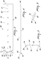
- Fig. 1 illustrates the cutting edge 10.
- the cutting edge 10 comprises a central member 12, a first flanking member 14 and a second flanking member 16.
- the central member 12 includes a first apexed terminal 18 and a second apexed terminal 20.
- the first and second apexed terminals 18, 20 are on opposed ends of the central member 12.
- Central member 12 includes a longitudinal axis 21.
- First and second apexed terminals 18, 20 are aligned on the longitudinal axis 21.
- First apex 22 of the first apexed terminal 18 and second apex 24 of the second apexed terminal 20 is positioned on the longitudinal axis 21.
- central member 12 includes at least one central cutting side 26.
- Central cutting side 26 is disposed between the first and second apexed terminals 18, 20.
- Central cutting side 26 is connected to the first and second apexed terminals 18, 20.
- Central cutting side 26 extends along the entire length of the central member 12.
- Central cutting side 26 is parallel with the longitudinal axis 21.
- the first flanking member 14 includes a first cutting side 28.
- First cutting side 28 extends along the entire side of the first flanking member 14.
- First cutting side 28 is parallel with a longitudinal axis 30 of the first flanking member 14.
- First flanking member 14 includes a first inner inclined end 32.
- First inner inclined end 32 is connected to the first cutting side 28.
- First inner inclined end 32 is angled relative to the first cutting side 28.
- First inner inclined end 32 is angled relative to the longitudinal axis 30.
- First flanking member 14 is positionable so as to be in abutting contact with central member 12.
- the first inner inclined end 32 is contiguously positionable to the first apexed terminal 18.
- First inner inclined end 32 is configured to match the configuration of the first apexed terminal 18.
- the second flanking member 16 includes a second cutting side 34.
- Second cutting side 34 extends along the entire side of the second flanking member 16. Second cutting side 34 is parallel with a longitudinal axis 36 of the second flanking member 16.
- Second flanking member 16 includes a second inner inclined end 38.
- Second inner inclined end 38 is connected to the second cutting side 34.
- Second inner inclined end 38 is angled relative to the second cutting side 34.
- Second inner inclined end 38 is angled relative to the longitudinal axis 36.
- Second flanking member 16 is positionable so as to be in abutting contact with central member 12.
- the second inner inclined end 38 is contiguously positionable to the second apexed terminal 20.
- Second inner inclined end 38 is configured to match the configuration of the second apexed terminal 20.
- first and second flanking members 14, 16 are moved relative to the central member 12.
- First and second flanking members 14, 16 and the central member 12 are positioned such that the longitudinal axes 21, 30, 36 are mutually aligned.
- First and second flanking members 14, 16 and the central member 12 are rectilinearly alignable such that the first and second cutting sides 28, 34 and the central cutting side 26 form a continuous cutting verge 40.
- First and second cutting sides 28, 34 and the central cutting side 26 are formed as a continuous edge for contacting work material or for contacting ground to be leveled.
- First and second flanking members 14, 16 are juxtaposed on opposite ends of the central member 12.
- the central member 12 further comprises a second central cutting side 42.
- Second central cutting side 42 is parallel to the central cutting side 26.
- Second central cutting side 42 is disposed between the first and second apexed terminals 18, 20.
- Second central cutting side 42 is connected to the first and second apexed terminals 18, 20.
- Second central cutting side 42 extends along the entire length of the central member 12.
- Second central cutting side 42 is parallel with the longitudinal axis 21.
- the central member 12 is rotated so that the second central cutting side 42 occupies the position of the central cutting side 26 such that the second central cutting side 42 forms a continuous blade verge with first and second cutting sides 28, 34.
- the central member 12 comprises a first central portion 44 and a second central portion 46.
- the first central portion 44 includes the first apexed terminal 18.
- the second central portion 46 includes the second apexed terminal 20.
- the first central portion 44 includes a first inner end 48 and the second central portion 46 includes a second inner end 50.
- First inner end 48 is disposed opposite the first apexed terminal 18.
- Second inner end 50 is disposed opposite the second apexed terminal 20.
- the first inner end 48 is abuttingly positionable to the second inner end 50.
- the first inner end 48 is contiguously positioned to the second inner end 50.
- the first flanking member 14 includes a first outer inclined end 52 that is opposite to the first inner inclined end 32.
- the second flanking member 16 includes a second outer inclined end 54 that is opposite to the second inner inclined end 38.
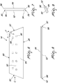
- a first central portion 44 of the central member 12 is illustrated.
- first central portion 44 includes parallel cutting sides that are portions of the central cutting side 26 and the second central cutting side 42.
- the first and second cutting side portions 56, 58 are formed between the first apexed terminal 18 and the first inner end 48.
- First and second cutting side portions 56, 58 each having a length of 1107.7mm.
- First inner end 48 has a height of 126.2mm.
- First inner end 48 is perpendicular to the first and second cutting side portions 56, 58.
- First central portion 44 includes a front central face 60.
- Front central face 60 is bounded by first and second cutting side portions 56, 58, first apexed terminal 18 and the first inner end 48.
- First central portion 44 being provided with holes 62 for receiving bolts or rivets to mount the first central portion 44 on the foldable blade 100.
- Holes 62 extends through the first central portion 44.
- the holes 62 are aligned along the longitudinal axis 21.
- the holes 62 are aligned on the longitudinal axis 21 so as to allow the central member 12 to be rotated such that second central cutting side 42 replaces the central cutting side 26 at the continuous cutting verge (40).
- the holes 62 are mutually spaced by a distance of 152.4mm. In an embodiment, the holes 62 are square shaped.
- the first apexed terminal 18 contains sloped sides 64.
- Each sloped side 64 extends between respective first and second cutting side portions 56, 58 and first apex 22.
- At least one sloped side 64 includes an angle ⁇ of 69° from the at least one central cutting side 26. Sloped sides 64 each having an angle ⁇ of 69° from the respective first and second cutting side portions 56, 58.
- Each sloped side 64 includes a length of 127.8mm.
- the second apexed terminal 20 includes sloped sides 66.
- each sloped side 66 extends between respective first and second cutting side portions 76, 78 and second apex 24.
- At least one sloped side 66 has an angle ⁇ of 69° from the at least one central cutting side 26.
- sloped sides 66 each having an angle ⁇ of 69° from the respective first and second cutting side portions 76, 78.
- each sloped side 66 has a length of 127.8mm.
- the first apex 22 of the first apexed terminal 18 extends beyond the end of the first and second cutting side portions 56, 58.
- the distance from apex 22 to the first inner end 48 is 1217.3mm.
- the longitudinal length of the apex 22 extending from a point on the longitudinal axis 21 corresponding to the end of the first and second cutting side portions 56, 58 is 109.6mm.
- the longitudinal length of the apex 24 extending from a point on the longitudinal axis 21 corresponding to the end of the respective first and second cutting side portions 76, 78 is 109.6mm.
- the apexes 22, 24 of the first and second apexed terminals 18, 20 extend beyond the respective opposite ends of the at least one central cutting side 26 at a longitudinal distance of 109.6mm
- the first central portion 44 includes a rear central face 70 opposite the front central face 60. Holes 62 extends from the front central face 60 to the rear central face 70. Front and rear central faces 60, 70 are mutually parallel. Rear central face 70 has a smaller dimension relative to the front central face 60. Rear central face 70 has a smaller surface area relative to the front central face 60.
- Front central surface 60 includes a transverse width of 254mm.
- Rear central face 70 includes a transverse width of 198.2mm.
- First and second cutting side portions 56, 58 each comprising a slanted surface 72 and a flat surface 74.
- the slanted surface 72 and the flat surface 74 are parallel to the longitudinal axis 21.
- Slanted surface 72 and the flat surface 74 extend along the entire length of the first and second cutting side portions 56, 58.
- the horizontal distance between each junction of the flat surface 74 and the oblique surface 68 from the centre of the adjacent hole 62 is 52.9mm.
- the horizontal distance is parallel to the longitudinal axis 21 of the central member 12.
- First and second cutting side portions 56, 58 includes a width of 19mm that extends between the rear central face 70 and the front central face 60.
- Each slanted surface 72 is inclined relative to the rear central face 70 at an angle of 20° to 30°.
- Each slanted surface 72 is inclined relative to the rear central face 70 at an angle of 25°.
- the vertical distance from the rear central face 70 and the front central face 60 is 27.9mm, the vertical distance is transverse to the longitudinal axis 21 of the central member 12. The vertical distance is measured from the edge of the rear central face 70 to the adjacent edge of the front central face 60.
- the edges of the rear central face 70 and the front central face 60 is parallel to the longitudinal axis 21.
- the first central portion 44 is a substantially flat panel with the apexed terminal 18 extending from the first and second cutting side portions 56, 58.
- the first apexed terminal 18 includes oblique surfaces 68 that are formed between front central face 60 and rear central face 70.
- Oblique surfaces 68 extends from respective first and second cutting side portions 56, 58 to apex 22.
- Oblique surfaces 68 is inclined from respective sloped sides 64.
- each oblique surface 68 is inclined relative to front central face 60 at an angle of 55° to 65° .
- Each oblique surface 68 is inclined relative to front central face 60 at an angle of 60°.
- the second apexed terminal 20 includes oblique surfaces 82 that are formed between front central face 60 and rear central face 70.
- Oblique surfaces 82 extends from respective first and second cutting side portions 76, 78 to apex 24.
- Oblique surfaces 82 is inclined from respective sloped sides 66.
- Each oblique surface 82 is inclined relative to front central face 60 at an angle of 59.5° to 60.5°.
- Each oblique surface 82 is inclined relative to front central face 60 at an angle of 60°.
- a first flanking member 14 is illustrated.
- First flanking member 14 includes a first limit side 80 opposite to the first cutting side 28.
- First limit side 80 is parallel to the first cutting side 28.
- First flanking member 14 includes the first outer inclined end 52 opposite to the first inner inclined end 32.
- First outer inclined end 52 and first inner inclined end 32 diverges from ends of first limit side 80 and connect to ends of first cutting side 28.
- First flanking member 14 has a trapezoidal shape.
- First limit side 80 has a length of 748mm.
- First cutting side 28 has a length of 943mm.
- First outer inclined end 52 and first inner inclined end 32 each having a length of 272.07mm.
- First inner inclined end 32 includes an angle ⁇ of 111° from the first limit side 80.
- second inclined end 38 of second flanking member 16 includes an angle ⁇ of 111° from the second limit side 90.
- First outer inclined end 52 and second outer inclined end 54 each having an angle ⁇ of 111° from the respective first and second limit sides 80, 90.
- First inclined end 32 and second inclined end 38 is configured so as to correspond with respective slopped sides 64, 66 of the central member 12.
- First flanking member 14 includes a first front flanking face 84.
- First front flanking face 84 is bounded by first outer inclined end 52, first inclined end 32, first cutting side 28 and first limit side 80.
- First flanking member 14 is provided with a set of apertures 86 and a set of openings 88 for receiving bolts or rivets to mount the first flanking member 14 on a foldable blade.
- Apertures 86 and openings 88 extends through the first flanking member 14.
- the apertures 86 is aligned along the longitudinal axis 36.
- the apertures 86 is mutually spaced by a distance of 152.4mm.
- the apertures 86 are square shaped.
- the openings 88 is positioned between the first limit side 80 and the set of apertures 86.
- the openings 88 are square shaped.
- the first flanking member 14 includes a first rear flanking face 92 opposite the first front flanking face 84. Apertures 86 and openings 88 extends from the first front flanking face 84 to the first rear flanking face 92. First front flanking face 84 and first rear flanking face 92 are mutually parallel. First rear flanking face 92 has a smaller dimension relative to the first front flanking face 84. First rear flanking face 92 has a smaller surface area relative to the first front flanking face 84.
- First front flanking face 84 includes a transverse width of 254 mm.
- First rear flanking face 92 includes a transverse width of 198.2 mm.
- First limit side 80 and first cutting side 28 each comprises a slanted surface 94 and a flat surface 96.
- the slanted surface 94 and the flat surface 96 are parallel to the longitudinal axis 36. Slanted surface 94 and the flat surface 96 extends along the entire length of the first limit side 80 and the first cutting side 28.
- First limit side 80 and first cutting side 28 includes a width of 25 mm that extends between the first front flanking face 84 and the first rear flanking face 92.
- Each slanted surface 94 is inclined relative to the first rear flanking face 92 at an angle of 20° to 30°.
- Each slanted surface 94 is inclined relative to the first rear flanking face 92 at an angle of 25°.
- the vertical distance from the first rear flanking face 92 and the first front flanking face 84 is 27.9mm.
- the first flanking member 14 is a substantially flat panel.
- the first inclined end 32 includes a first bevel surface 98 that is formed between first front flanking face 84 and the first rear flanking face 92.
- First bevel surface 98 extends between first limit side 80 and the first cutting side 28 (not shown).
- First bevel surface 98 is inclined relative to first flanking face 84.
- first outer inclined end is provided with a first outer bevel surface 99.
- the first outer bevel surface 99 is formed between first front flanking face 84 and first rear flanking faces 92.
- First outer bevel surface 99 extends between limit side 80 and cutting side 28.
- first bevel surface 98 is inclined relative to first rear flanking face 92 at an angle of 59.5° to 60.5°.
- First bevel surface 98 is inclined relative to first rear flanking face 92 at an angle of 60° .
- the second inclined end 38 includes a second bevel surface 108 that is formed between second front flanking face 110 and the second rear flanking face 112. Second bevel surface 108 extends between second limit side 114 and the second cutting side 34 (not shown). Second bevel surface 108 is inclined relative to second front flanking face 110.
- second outer inclined end 54 includes a second outer bevel surface 109.
- the second outer bevel surface 109 is formed between second front flanking face 110 and second rear flanking face 112. Second outer bevel surface 109 extends between limit side 114 and cutting side 34.
- Second bevel surface 108 is inclined relative to second rear flanking face 112 at an angle of 59.5° to 60.5°. Second bevel surface 108 is inclined relative to second rear flanking face 112 at an angle of 60°.
- the cutting edge 10 is mounted to a foldable blade 100.
- Foldable blade 100 includes a centre element 102, a first flanking element 104 and a second flanking element 106.
- Central member 12 is mounted to the centre element 102.
- First flaking member 14 is mounted to first flanking element 104.
- Second flaking member 106 is mounted to second flanking element 106.
- Foldable blade 100 is in an unfolded configuration with first and second flanking elements 104, 106 are rectilinearly aligned with the centre element 102.
- first and second flanking members 14 are positioned rectilinearly with the central member 12.
- the foldable blade 100 is in a folded configuration with first and second flanking elements 104, 106 is inclined relative to the centre element 102.
- the first and second flanking members 14, 16 is inclined relative to the central member 12.
- This disclosure describes a cutting edge 10 for a foldable blade 100 of a work machine.
- the foldable blade 100 is folded so that the overall length thereof is reduced for transportation of the work machine.
- the cutting edge 10 includes at least three members 12, 14, 16.
- the cutting edge 10 includes four members with first and second central portions 44, 46.
- the cutting edge 10 is mounted to the foldable blade 100.
- flanking members 14, 16 is positioned so as to be rectilinearly aligned to the central member 12.
- First and second inclined ends 32, 38 are suitably configured to correspond with the first and second apexed terminals 18, 20 so that the flanking members 14, 16 are flush with the central member 12.
- the central cutting side 26 is aligned with the first and second cutting sides 28, 34 so as to form a continuous cutting verge 40.
- the cutting verge 40 contacts the work materials during work operations.
Landscapes
- Engineering & Computer Science (AREA)
- Mechanical Engineering (AREA)
- Mining & Mineral Resources (AREA)
- Civil Engineering (AREA)
- General Engineering & Computer Science (AREA)
- Structural Engineering (AREA)
- Sawing (AREA)
- Harvester Elements (AREA)
Claims (10)
- Un bord de coupe (10) pour une lame pliante (100) d'une machine de travail, le bord de coupe (10) comprenant : un élément central (12) ayant des première et seconde terminaisons à apex (18, 20) et au moins un côté coupant central (26) disposé entre les première et seconde terminaisons à apex (18, 20) ; un premier élément adjacent (14) ayant un premier côté coupant (28) et une première extrémité intérieure inclinée (32), la première extrémité intérieure inclinée (32) étant positionnable de manière contiguë à la première terminaison à apex (18) ; et un second élément adjacent (16) ayant un second côté coupant (34) et une seconde extrémité intérieure inclinée (38), la seconde extrémité intérieure inclinée (38) étant positionnable de manière contiguë à la seconde terminaison à apex (20), les premier et second éléments adjacents (14, 16) et l'élément central (12) étant alignables rectilignement de façon que les premier et second côtés coupants (28, 34) et le côté coupant central (26) forment une rive de coupe continue (40), l'élément central (12) comprenant un second côté coupant central (42) parallèle au au moins un côté coupant central (26), et l'élément central (12) étant rotatif de façon que le second côté coupant central (42) forme la rive de coupe continue (40) avec les premier et second côtés coupants (28, 34), caractérisé en ce que les première et seconde terminaisons à apex (18, 20) ont des surfaces obliques (68, 82) formées entre une face centrale avant (60) et une face centrale arrière (70) de l'élément central (12), la première extrémité intérieure inclinée (32) ayant une première surface biseautée (98) formée entre une première face adjacente avant (84) et une première face adjacente arrière (92) du premier élément adjacent (14), et la seconde extrémité intérieure inclinée (38) ayant une seconde surface biseautée (108) formée entre une seconde face adjacente avant (110) et une seconde face adjacente arrière (112) du second élément adjacent (16).
- Le bord de coupe (10) selon la revendication 1, dans lequel les première et seconde terminaisons à apex (18, 20) ont des côtés pentus respectifs (64, 66), au moins un côté pentu respectif (64, 66) ayant un angle (α) de 69° à partir d'au moins un côté coupant (26).
- Le bord de coupe (10) selon l'une quelconque des revendications précédentes, dans lequel les apex (22, 24) des première et seconde terminaisons à apex (18, 20) s'étendant au-delà des extrémités opposées respectives du au moins un côté coupant central (26) sur une distance longitudinale de 109,6 mm.
- Le bord de coupe (10) selon la revendication 1, dans lequel chaque surface oblique (68, 82) a un angle de 59,5° à 60,5° à partir de la face centrale avant (60).
- Le bord de coupe (10) selon l'une quelconque des revendications précédentes, dans lequel la première extrémité intérieure inclinée (32) et la seconde extrémité intérieure inclinée (38) ayant des angles de 69° respectivement à partir des premier et second côtés limites (80, 90).
- Le bord de coupe (10) selon la revendication 1, dans lequel la première surface biseautée (98) a un angle de 59,5° à 60,5° à partir de la première face adjacente arrière (92) et la seconde surface biseautée (108) a un angle de 59,5° à 60,5° par rapport à la seconde face adjacente arrière (112).
- Le bord de coupe (10) selon l'une quelconque des revendications précédentes, dans lequel l'élément central (12) comprend une première portion centrale (44) ayant la première terminaison à apex (18) et une seconde portion centrale (46) ayant la seconde terminaison à apex (20).
- Le bord de coupe (10) selon la revendication 7, dans lequel la première portion centrale (44) a une première extrémité intérieure (48) à l'opposé de la première terminaison à apex (18), et la seconde portion centrale (46) a une seconde extrémité intérieure (50) à l'opposé de la seconde terminaison à apex (20), la première extrémité intérieure (48) étant positionnable en butée contre la seconde extrémité intérieure (50) .
- Le bord de coupe (10) selon l'une quelconque des revendications précédentes, dans lequel des trous (62) sont ménagés le long de l'axe longitudinal (21) de l'élément central (12), de façon à permettre la rotation de l'élément central (12) de façon que le second côté coupant central (42) remplace le au moins un côté coupant central (26) au niveau de la rive de coupe continue (40).
- Une lame pliante (100) d'une machine de travail, la lame pliante (100) comprenant un bord de coupe (10) de l'une quelconque des revendications précédentes, dans lequel l'élément central (12) est monté sur une partie centrale (102), le premier élément adjacent (14) étant monté sur une première partie adjacente (104), et le second élément adjacent (16) étant monté sur la seconde partie adjacente (106), de façon que le bord de coupe (10) soit aligné pour former une rive de coupe continue (40) lorsque les première et seconde parties adjacentes (104, 106) sont alignées rectilignement avec la partie centrale (102).
Priority Applications (2)
| Application Number | Priority Date | Filing Date | Title |
|---|---|---|---|
| EP13162962.8A EP2789751B1 (fr) | 2013-04-09 | 2013-04-09 | Bord de coupe de lame pliable d'une machine de travail |
| CN201420165152.2U CN203768965U (zh) | 2013-04-09 | 2014-04-08 | 作业机器的可折叠铲刀的切削刃 |
Applications Claiming Priority (1)
| Application Number | Priority Date | Filing Date | Title |
|---|---|---|---|
| EP13162962.8A EP2789751B1 (fr) | 2013-04-09 | 2013-04-09 | Bord de coupe de lame pliable d'une machine de travail |
Publications (2)
| Publication Number | Publication Date |
|---|---|
| EP2789751A1 EP2789751A1 (fr) | 2014-10-15 |
| EP2789751B1 true EP2789751B1 (fr) | 2018-10-10 |
Family
ID=48050545
Family Applications (1)
| Application Number | Title | Priority Date | Filing Date |
|---|---|---|---|
| EP13162962.8A Active EP2789751B1 (fr) | 2013-04-09 | 2013-04-09 | Bord de coupe de lame pliable d'une machine de travail |
Country Status (2)
| Country | Link |
|---|---|
| EP (1) | EP2789751B1 (fr) |
| CN (1) | CN203768965U (fr) |
Families Citing this family (3)
| Publication number | Priority date | Publication date | Assignee | Title |
|---|---|---|---|---|
| CN105178374B (zh) * | 2014-11-27 | 2018-05-08 | 上海彭浦机器厂有限公司 | 一种折叠式推土铲及推土机 |
| US10633820B2 (en) * | 2016-12-22 | 2020-04-28 | Caterpillar Inc. | Cutter for dozing blade assembly and body section for same |
| JP7008556B2 (ja) * | 2018-03-26 | 2022-02-10 | 本田技研工業株式会社 | 切除用刃具 |
Citations (1)
| Publication number | Priority date | Publication date | Assignee | Title |
|---|---|---|---|---|
| US4390071A (en) * | 1979-11-23 | 1983-06-28 | Paper, Calmenson & Co. | Replaceable cutting blade assembly for dozers |
Family Cites Families (4)
| Publication number | Priority date | Publication date | Assignee | Title |
|---|---|---|---|---|
| US5396963A (en) | 1991-10-09 | 1995-03-14 | Curry; John N. | Blades for earth moving machines |
| US6112438A (en) * | 1998-08-14 | 2000-09-05 | Pro-Tech Welding & Fabrication, Inc. | Snow plow |
| US6484813B2 (en) * | 2001-04-16 | 2002-11-26 | Tapio Construction, Inc. | Bulldozer attachment to facilitate grading |
| US8689897B2 (en) * | 2010-12-18 | 2014-04-08 | Caterpillar Inc. | Tractor blade assembly |
-
2013
- 2013-04-09 EP EP13162962.8A patent/EP2789751B1/fr active Active
-
2014
- 2014-04-08 CN CN201420165152.2U patent/CN203768965U/zh not_active Expired - Lifetime
Patent Citations (1)
| Publication number | Priority date | Publication date | Assignee | Title |
|---|---|---|---|---|
| US4390071A (en) * | 1979-11-23 | 1983-06-28 | Paper, Calmenson & Co. | Replaceable cutting blade assembly for dozers |
Also Published As
| Publication number | Publication date |
|---|---|
| EP2789751A1 (fr) | 2014-10-15 |
| CN203768965U (zh) | 2014-08-13 |
Similar Documents
| Publication | Publication Date | Title |
|---|---|---|
| US3961788A (en) | Bulldozer blade with improved tip and end bit | |
| AU2015336923B9 (en) | Wear protection assembly | |
| US8689897B2 (en) | Tractor blade assembly | |
| CA1044728A (fr) | Rive coupante amovible et adaptateur de dents de creusage pour bennes de chargeuses | |
| US8875422B2 (en) | Excavating bucket for construction machine | |
| CN106687646B (zh) | 机具切割边缘磨损构件 | |
| US8966791B2 (en) | Staggered edge excavator buckets | |
| EP2789751B1 (fr) | Bord de coupe de lame pliable d'une machine de travail | |
| CN106715805A (zh) | 机具磨损构件 | |
| WO2016022420A1 (fr) | Élément d'usure d'instrument à haute performance | |
| US20150060097A1 (en) | Implement End Cutting-Bit | |
| US20140041886A1 (en) | Cutter For Dozing Blade, Service Package, And Method | |
| EP2154294A1 (fr) | Lame de raclage extensible | |
| US7351028B2 (en) | Work machine adapter and method | |
| ES3058544T3 (en) | Overlapping cutting edge tip system | |
| US4407081A (en) | Bucket tooth attachment means | |
| CN106715804A (zh) | 机具端部刀头磨损构件 | |
| RU2722637C2 (ru) | Изнашиваемый элемент | |
| CN107075831A (zh) | 具有磨损指示器的机具磨损构件 | |
| US20110126434A1 (en) | Angled edge bucket excavation tool | |
| US20130161037A1 (en) | Track-type tractor, dozing blade assembly, and dozing blade with steep center segment | |
| US3038267A (en) | Bulldozer for heavy duty and ripping operations | |
| CN111877425A (zh) | 用于刀片的耐磨板 | |
| CN104011303A (zh) | 用于铲斗的附装件 | |
| US4601119A (en) | Corner tooth for a bucket |
Legal Events
| Date | Code | Title | Description |
|---|---|---|---|
| PUAI | Public reference made under article 153(3) epc to a published international application that has entered the european phase |
Free format text: ORIGINAL CODE: 0009012 |
|
| 17P | Request for examination filed |
Effective date: 20130409 |
|
| AK | Designated contracting states |
Kind code of ref document: A1 Designated state(s): AL AT BE BG CH CY CZ DE DK EE ES FI FR GB GR HR HU IE IS IT LI LT LU LV MC MK MT NL NO PL PT RO RS SE SI SK SM TR |
|
| AX | Request for extension of the european patent |
Extension state: BA ME |
|
| R17P | Request for examination filed (corrected) |
Effective date: 20150227 |
|
| RBV | Designated contracting states (corrected) |
Designated state(s): AL AT BE BG CH CY CZ DE DK EE ES FI FR GB GR HR HU IE IS IT LI LT LU LV MC MK MT NL NO PL PT RO RS SE SI SK SM TR |
|
| STAA | Information on the status of an ep patent application or granted ep patent |
Free format text: STATUS: EXAMINATION IS IN PROGRESS |
|
| 17Q | First examination report despatched |
Effective date: 20161021 |
|
| GRAP | Despatch of communication of intention to grant a patent |
Free format text: ORIGINAL CODE: EPIDOSNIGR1 |
|
| STAA | Information on the status of an ep patent application or granted ep patent |
Free format text: STATUS: GRANT OF PATENT IS INTENDED |
|
| INTG | Intention to grant announced |
Effective date: 20180423 |
|
| GRAS | Grant fee paid |
Free format text: ORIGINAL CODE: EPIDOSNIGR3 |
|
| GRAA | (expected) grant |
Free format text: ORIGINAL CODE: 0009210 |
|
| STAA | Information on the status of an ep patent application or granted ep patent |
Free format text: STATUS: THE PATENT HAS BEEN GRANTED |
|
| AK | Designated contracting states |
Kind code of ref document: B1 Designated state(s): AL AT BE BG CH CY CZ DE DK EE ES FI FR GB GR HR HU IE IS IT LI LT LU LV MC MK MT NL NO PL PT RO RS SE SI SK SM TR |
|
| REG | Reference to a national code |
Ref country code: GB Ref legal event code: FG4D |
|
| REG | Reference to a national code |
Ref country code: CH Ref legal event code: EP Ref country code: AT Ref legal event code: REF Ref document number: 1051412 Country of ref document: AT Kind code of ref document: T Effective date: 20181015 |
|
| REG | Reference to a national code |
Ref country code: IE Ref legal event code: FG4D |
|
| REG | Reference to a national code |
Ref country code: DE Ref legal event code: R096 Ref document number: 602013044728 Country of ref document: DE |
|
| REG | Reference to a national code |
Ref country code: CH Ref legal event code: NV Representative=s name: MODIANO AND PARTNERS S.A., CH |
|
| REG | Reference to a national code |
Ref country code: NL Ref legal event code: MP Effective date: 20181010 |
|
| REG | Reference to a national code |
Ref country code: LT Ref legal event code: MG4D |
|
| REG | Reference to a national code |
Ref country code: AT Ref legal event code: MK05 Ref document number: 1051412 Country of ref document: AT Kind code of ref document: T Effective date: 20181010 |
|
| PG25 | Lapsed in a contracting state [announced via postgrant information from national office to epo] |
Ref country code: NL Free format text: LAPSE BECAUSE OF FAILURE TO SUBMIT A TRANSLATION OF THE DESCRIPTION OR TO PAY THE FEE WITHIN THE PRESCRIBED TIME-LIMIT Effective date: 20181010 |
|
| PG25 | Lapsed in a contracting state [announced via postgrant information from national office to epo] |
Ref country code: ES Free format text: LAPSE BECAUSE OF FAILURE TO SUBMIT A TRANSLATION OF THE DESCRIPTION OR TO PAY THE FEE WITHIN THE PRESCRIBED TIME-LIMIT Effective date: 20181010 Ref country code: LV Free format text: LAPSE BECAUSE OF FAILURE TO SUBMIT A TRANSLATION OF THE DESCRIPTION OR TO PAY THE FEE WITHIN THE PRESCRIBED TIME-LIMIT Effective date: 20181010 Ref country code: AT Free format text: LAPSE BECAUSE OF FAILURE TO SUBMIT A TRANSLATION OF THE DESCRIPTION OR TO PAY THE FEE WITHIN THE PRESCRIBED TIME-LIMIT Effective date: 20181010 Ref country code: FI Free format text: LAPSE BECAUSE OF FAILURE TO SUBMIT A TRANSLATION OF THE DESCRIPTION OR TO PAY THE FEE WITHIN THE PRESCRIBED TIME-LIMIT Effective date: 20181010 Ref country code: NO Free format text: LAPSE BECAUSE OF FAILURE TO SUBMIT A TRANSLATION OF THE DESCRIPTION OR TO PAY THE FEE WITHIN THE PRESCRIBED TIME-LIMIT Effective date: 20190110 Ref country code: IS Free format text: LAPSE BECAUSE OF FAILURE TO SUBMIT A TRANSLATION OF THE DESCRIPTION OR TO PAY THE FEE WITHIN THE PRESCRIBED TIME-LIMIT Effective date: 20190210 Ref country code: PL Free format text: LAPSE BECAUSE OF FAILURE TO SUBMIT A TRANSLATION OF THE DESCRIPTION OR TO PAY THE FEE WITHIN THE PRESCRIBED TIME-LIMIT Effective date: 20181010 Ref country code: HR Free format text: LAPSE BECAUSE OF FAILURE TO SUBMIT A TRANSLATION OF THE DESCRIPTION OR TO PAY THE FEE WITHIN THE PRESCRIBED TIME-LIMIT Effective date: 20181010 Ref country code: LT Free format text: LAPSE BECAUSE OF FAILURE TO SUBMIT A TRANSLATION OF THE DESCRIPTION OR TO PAY THE FEE WITHIN THE PRESCRIBED TIME-LIMIT Effective date: 20181010 Ref country code: BG Free format text: LAPSE BECAUSE OF FAILURE TO SUBMIT A TRANSLATION OF THE DESCRIPTION OR TO PAY THE FEE WITHIN THE PRESCRIBED TIME-LIMIT Effective date: 20190110 |
|
| PG25 | Lapsed in a contracting state [announced via postgrant information from national office to epo] |
Ref country code: GR Free format text: LAPSE BECAUSE OF FAILURE TO SUBMIT A TRANSLATION OF THE DESCRIPTION OR TO PAY THE FEE WITHIN THE PRESCRIBED TIME-LIMIT Effective date: 20190111 Ref country code: SE Free format text: LAPSE BECAUSE OF FAILURE TO SUBMIT A TRANSLATION OF THE DESCRIPTION OR TO PAY THE FEE WITHIN THE PRESCRIBED TIME-LIMIT Effective date: 20181010 Ref country code: PT Free format text: LAPSE BECAUSE OF FAILURE TO SUBMIT A TRANSLATION OF THE DESCRIPTION OR TO PAY THE FEE WITHIN THE PRESCRIBED TIME-LIMIT Effective date: 20190210 Ref country code: AL Free format text: LAPSE BECAUSE OF FAILURE TO SUBMIT A TRANSLATION OF THE DESCRIPTION OR TO PAY THE FEE WITHIN THE PRESCRIBED TIME-LIMIT Effective date: 20181010 Ref country code: RS Free format text: LAPSE BECAUSE OF FAILURE TO SUBMIT A TRANSLATION OF THE DESCRIPTION OR TO PAY THE FEE WITHIN THE PRESCRIBED TIME-LIMIT Effective date: 20181010 |
|
| REG | Reference to a national code |
Ref country code: DE Ref legal event code: R097 Ref document number: 602013044728 Country of ref document: DE |
|
| PG25 | Lapsed in a contracting state [announced via postgrant information from national office to epo] |
Ref country code: CZ Free format text: LAPSE BECAUSE OF FAILURE TO SUBMIT A TRANSLATION OF THE DESCRIPTION OR TO PAY THE FEE WITHIN THE PRESCRIBED TIME-LIMIT Effective date: 20181010 Ref country code: IT Free format text: LAPSE BECAUSE OF FAILURE TO SUBMIT A TRANSLATION OF THE DESCRIPTION OR TO PAY THE FEE WITHIN THE PRESCRIBED TIME-LIMIT Effective date: 20181010 Ref country code: DK Free format text: LAPSE BECAUSE OF FAILURE TO SUBMIT A TRANSLATION OF THE DESCRIPTION OR TO PAY THE FEE WITHIN THE PRESCRIBED TIME-LIMIT Effective date: 20181010 |
|
| PLBE | No opposition filed within time limit |
Free format text: ORIGINAL CODE: 0009261 |
|
| STAA | Information on the status of an ep patent application or granted ep patent |
Free format text: STATUS: NO OPPOSITION FILED WITHIN TIME LIMIT |
|
| PG25 | Lapsed in a contracting state [announced via postgrant information from national office to epo] |
Ref country code: SK Free format text: LAPSE BECAUSE OF FAILURE TO SUBMIT A TRANSLATION OF THE DESCRIPTION OR TO PAY THE FEE WITHIN THE PRESCRIBED TIME-LIMIT Effective date: 20181010 Ref country code: RO Free format text: LAPSE BECAUSE OF FAILURE TO SUBMIT A TRANSLATION OF THE DESCRIPTION OR TO PAY THE FEE WITHIN THE PRESCRIBED TIME-LIMIT Effective date: 20181010 Ref country code: EE Free format text: LAPSE BECAUSE OF FAILURE TO SUBMIT A TRANSLATION OF THE DESCRIPTION OR TO PAY THE FEE WITHIN THE PRESCRIBED TIME-LIMIT Effective date: 20181010 Ref country code: SM Free format text: LAPSE BECAUSE OF FAILURE TO SUBMIT A TRANSLATION OF THE DESCRIPTION OR TO PAY THE FEE WITHIN THE PRESCRIBED TIME-LIMIT Effective date: 20181010 |
|
| 26N | No opposition filed |
Effective date: 20190711 |
|
| PG25 | Lapsed in a contracting state [announced via postgrant information from national office to epo] |
Ref country code: SI Free format text: LAPSE BECAUSE OF FAILURE TO SUBMIT A TRANSLATION OF THE DESCRIPTION OR TO PAY THE FEE WITHIN THE PRESCRIBED TIME-LIMIT Effective date: 20181010 |
|
| REG | Reference to a national code |
Ref country code: BE Ref legal event code: MM Effective date: 20190430 |
|
| GBPC | Gb: european patent ceased through non-payment of renewal fee |
Effective date: 20190409 |
|
| PG25 | Lapsed in a contracting state [announced via postgrant information from national office to epo] |
Ref country code: LU Free format text: LAPSE BECAUSE OF NON-PAYMENT OF DUE FEES Effective date: 20190409 Ref country code: MC Free format text: LAPSE BECAUSE OF FAILURE TO SUBMIT A TRANSLATION OF THE DESCRIPTION OR TO PAY THE FEE WITHIN THE PRESCRIBED TIME-LIMIT Effective date: 20181010 |
|
| PG25 | Lapsed in a contracting state [announced via postgrant information from national office to epo] |
Ref country code: GB Free format text: LAPSE BECAUSE OF NON-PAYMENT OF DUE FEES Effective date: 20190409 |
|
| PG25 | Lapsed in a contracting state [announced via postgrant information from national office to epo] |
Ref country code: BE Free format text: LAPSE BECAUSE OF NON-PAYMENT OF DUE FEES Effective date: 20190430 |
|
| PG25 | Lapsed in a contracting state [announced via postgrant information from national office to epo] |
Ref country code: TR Free format text: LAPSE BECAUSE OF FAILURE TO SUBMIT A TRANSLATION OF THE DESCRIPTION OR TO PAY THE FEE WITHIN THE PRESCRIBED TIME-LIMIT Effective date: 20181010 |
|
| PG25 | Lapsed in a contracting state [announced via postgrant information from national office to epo] |
Ref country code: IE Free format text: LAPSE BECAUSE OF NON-PAYMENT OF DUE FEES Effective date: 20190409 |
|
| PG25 | Lapsed in a contracting state [announced via postgrant information from national office to epo] |
Ref country code: CY Free format text: LAPSE BECAUSE OF FAILURE TO SUBMIT A TRANSLATION OF THE DESCRIPTION OR TO PAY THE FEE WITHIN THE PRESCRIBED TIME-LIMIT Effective date: 20181010 |
|
| PG25 | Lapsed in a contracting state [announced via postgrant information from national office to epo] |
Ref country code: MT Free format text: LAPSE BECAUSE OF FAILURE TO SUBMIT A TRANSLATION OF THE DESCRIPTION OR TO PAY THE FEE WITHIN THE PRESCRIBED TIME-LIMIT Effective date: 20181010 Ref country code: HU Free format text: LAPSE BECAUSE OF FAILURE TO SUBMIT A TRANSLATION OF THE DESCRIPTION OR TO PAY THE FEE WITHIN THE PRESCRIBED TIME-LIMIT; INVALID AB INITIO Effective date: 20130409 |
|
| PG25 | Lapsed in a contracting state [announced via postgrant information from national office to epo] |
Ref country code: MK Free format text: LAPSE BECAUSE OF FAILURE TO SUBMIT A TRANSLATION OF THE DESCRIPTION OR TO PAY THE FEE WITHIN THE PRESCRIBED TIME-LIMIT Effective date: 20181010 |
|
| REG | Reference to a national code |
Ref country code: DE Ref legal event code: R081 Ref document number: 602013044728 Country of ref document: DE Owner name: CATERPILLAR FRANCE S.A.S., FR Free format text: FORMER OWNER: CATERPILLAR FRANCE, GRENOBLE, FR |
|
| P01 | Opt-out of the competence of the unified patent court (upc) registered |
Effective date: 20230517 |
|
| PGFP | Annual fee paid to national office [announced via postgrant information from national office to epo] |
Ref country code: DE Payment date: 20250319 Year of fee payment: 13 |
|
| PGFP | Annual fee paid to national office [announced via postgrant information from national office to epo] |
Ref country code: CH Payment date: 20250501 Year of fee payment: 13 |
|
| PGFP | Annual fee paid to national office [announced via postgrant information from national office to epo] |
Ref country code: FR Payment date: 20260319 Year of fee payment: 14 |