EP2796649A1 - Closing system of a room by means of pull sliding panels and kit for assembly of said system - Google Patents
Closing system of a room by means of pull sliding panels and kit for assembly of said system Download PDFInfo
- Publication number
- EP2796649A1 EP2796649A1 EP20140165321 EP14165321A EP2796649A1 EP 2796649 A1 EP2796649 A1 EP 2796649A1 EP 20140165321 EP20140165321 EP 20140165321 EP 14165321 A EP14165321 A EP 14165321A EP 2796649 A1 EP2796649 A1 EP 2796649A1
- Authority
- EP
- European Patent Office
- Prior art keywords
- panel
- panels
- abutment
- pulling
- closing
- Prior art date
- Legal status (The legal status is an assumption and is not a legal conclusion. Google has not performed a legal analysis and makes no representation as to the accuracy of the status listed.)
- Withdrawn
Links
Images




Classifications
-
- E—FIXED CONSTRUCTIONS
- E05—LOCKS; KEYS; WINDOW OR DOOR FITTINGS; SAFES
- E05D—HINGES OR SUSPENSION DEVICES FOR DOORS, WINDOWS OR WINGS
- E05D15/00—Suspension arrangements for wings
- E05D15/06—Suspension arrangements for wings for wings sliding horizontally more or less in their own plane
- E05D15/08—Suspension arrangements for wings for wings sliding horizontally more or less in their own plane consisting of two or more independent parts movable each in its own guides
-
- E—FIXED CONSTRUCTIONS
- E05—LOCKS; KEYS; WINDOW OR DOOR FITTINGS; SAFES
- E05F—DEVICES FOR MOVING WINGS INTO OPEN OR CLOSED POSITION; CHECKS FOR WINGS; WING FITTINGS NOT OTHERWISE PROVIDED FOR, CONCERNED WITH THE FUNCTIONING OF THE WING
- E05F17/00—Special devices for shifting a plurality of wings operated simultaneously
- E05F2017/005—Special devices for shifting a plurality of wings operated simultaneously for sliding wings
- E05F2017/007—Special devices for shifting a plurality of wings operated simultaneously for sliding wings with means for interlocking the wings
-
- E—FIXED CONSTRUCTIONS
- E05—LOCKS; KEYS; WINDOW OR DOOR FITTINGS; SAFES
- E05Y—INDEXING SCHEME ASSOCIATED WITH SUBCLASSES E05D AND E05F, RELATING TO CONSTRUCTION ELEMENTS, ELECTRIC CONTROL, POWER SUPPLY, POWER SIGNAL OR TRANSMISSION, USER INTERFACES, MOUNTING OR COUPLING, DETAILS, ACCESSORIES, AUXILIARY OPERATIONS NOT OTHERWISE PROVIDED FOR, APPLICATION THEREOF
- E05Y2201/00—Constructional elements; Accessories therefor
- E05Y2201/20—Brakes; Disengaging means; Holders; Stops; Valves; Accessories therefor
- E05Y2201/218—Holders
- E05Y2201/22—Locks
-
- E—FIXED CONSTRUCTIONS
- E05—LOCKS; KEYS; WINDOW OR DOOR FITTINGS; SAFES
- E05Y—INDEXING SCHEME ASSOCIATED WITH SUBCLASSES E05D AND E05F, RELATING TO CONSTRUCTION ELEMENTS, ELECTRIC CONTROL, POWER SUPPLY, POWER SIGNAL OR TRANSMISSION, USER INTERFACES, MOUNTING OR COUPLING, DETAILS, ACCESSORIES, AUXILIARY OPERATIONS NOT OTHERWISE PROVIDED FOR, APPLICATION THEREOF
- E05Y2900/00—Application of doors, windows, wings or fittings thereof
- E05Y2900/10—Application of doors, windows, wings or fittings thereof for buildings or parts thereof
- E05Y2900/13—Type of wing
- E05Y2900/132—Doors
Definitions
- the present invention relates to the field of doors for closing rooms inside buildings. More in particular, the invention relates to a closing system of a room by means of pull sliding panels, preferably but not exclusively of the type made of glass or crystal.
- the invention also relates to a kit for assembly of the aforesaid closing system.
- the panels are hung from trolleys sliding on guides fixed to the ceiling or to the wall, and movement of the panels generally takes place by pulling.
- the user pulls the panel that will be the end closing panel of the opening of the room; during translation, this panel, by means of abutment bodies positioned at the upper trolleys, comes into contact with counter-abutment bodies present on the trolleys of the immediately contiguous panel, pulling it toward the closed position.
- the second panel moved will be provided with abutment bodies and the third panel will be provided with counter-abutment bodies, so that during movement of the second panel the third panel is also moved.
- the movement for opening the room i.e. movement of the panels toward the stacked position, takes place substantially in the opposite direction, again by pulling.
- a first problem is linked, for example, to the footprint of the panels when they are in stacked position.
- the abutment bodies and the counter-abutment bodies are spaced apart on the trolleys, above the panels, with a configuration that obliges the outer edges of the panels, i.e. the edges facing the closed position, to remain staggered from one another, with an evident increase in the footprint of the stacked position and reduction of the opening of the room, which increases as the number of sliding panels used increases.
- the panels tend to pivot about an axis corresponding substantially to the sliding surface of the trolleys on the guides.
- the panels due to imperfections during installation or small variations in the structure with which they are associated, can often lose their correct horizontal arrangement, so that the panels tend to move toward the stacked or closed position, even when this is not required.
- the main object of the present invention is to solve the aforesaid problems by producing a closing system of a room by means of pull sliding panels, which is of simple construction, and a kit for the assembly of said system.
- Another important object of the present invention is that of producing a closing system of a room by means of pull sliding panels that is reliable in its operation.
- Yet another important object of the present invention is that of producing a closing system of a room by means of pull sliding panels that is simple to install.
- One more important object of the present invention is that of producing a closing system of a room by means of pull sliding panels that overcomes or reduces possible pivoting of the panels during movement.
- a further important object of the present invention is that of producing a closing system of a room by means of pull sliding panels that allows stable positioning of the panels in the operating positions thereof.
- the invention relates in particular to sliding panels without a perimeter frame in which pulling devices could be concealed.
- the invention relates to a system provided with elements or kits to be fitted substantially on the outer surface of the panels. It is understood that these elements or kits could also be fitted to the outer surface of panels with a perimeter frame.
- the closing system of a room by means of pull sliding panels comprises:
- the closing system of a room comprises at least three panels; of said at least three panels there are present a last panel adapted to close the room on the opposite side thereof with respect to the first panel, and a second last panel that precedes the last panel; in proximity of the inner and outer edges of the second last panel there are associated said abutment elements for pulling contiguous panels; there being associated with said last panel at least one said guiding and pulling unit fixed in proximity of the outer edge of the last panel, which comprises a portion of sliding guide for the lower edge of the second last panel, and counter abutment portions for abutment elements of the second last panel; the system is such that in the movement from the stacked/open position to the closed position, the abutment element associated with the inner edge of the second last panel that precedes the last panel in movement, impacts against a first counter abutment portion of the guiding and pulling unit associated with the last panel that follows, pulling with it said last panel, while, in the movement from the closed position to the stacked/open position
- a said guiding and pulling unit comprising a portion of sliding guide for the lower edge of the contiguous panel that precedes it, and counter abutment portions for abutment elements of the contiguous panel that precedes it, so that in the movement from the stacked/open position to the closed position, an abutment element, associated with the inner edge of the panel that precedes said intermediate panel, impacts against a first said counter abutment portion associated with said intermediate panel that follows, pulling with it the intermediate panel, while, in the movement from the closed position to the stacked/open position, the abutment element associated with the outer edge of the panel that precedes the intermediate
- intermediate panel can also be intended as the last panel, i.e. a panel subsequent to the first panel; therefore, in a system with two panels, intermediate panel can also be intended as the second and last panel of the system.
- each panel pulls a respective contiguous panel both in the movement to close the room, and in the movement to stack/open the panels (in the closing movement the contiguous panel moved is pulled, while in the opening movement the contiguous panel moved is pushed).
- the abutment elements for pulling contiguous panels, and the at least one guiding and pulling unit fixed in proximity of the outer edge at least of said second panel, or of the intermediate panel, are fixed close to the lower edge of the respective panels.
- the abutment elements for pulling contiguous panels, and the at least one guiding and pulling unit can be designed to be fixed at a distance from the lower edge comprised between around 1/20 and 1/200 of the height of the panel to which they are fixed. It must be clear that the distance from the lower edge is fixed and cannot be varied during use; the range indicated above is a range related to the design phase of the system.
- the outer edges of the panels are substantially aligned when the panels are in said stacked position.
- the system can comprise a guide to be fixed to the floor in which there is arranged slidingly the last panel of the series of panels, i.e. the last panel to be pulled during the opening movement.
- the guiding and pulling unit comprises a sandwich locking portion to the outer edge of the intermediate panel; from one side of the locking portion there extends an appendage forming a said abutment element; on the side of the locking portion, opposite said appendage with respect to the panel, there is defined, at a distance from the lower edge of the panel substantially corresponding to the distance of the appendage from the lower edge, a pair of seats open in opposite directions toward the opening or closing direction of the panels, for housing a respective said appendage, in which there are defined respective counter abutment portions for the abutment elements of the panel that precedes in movement; this guiding and pulling unit comprises, on the same side of the panel in which the seats are present, the aforesaid portion of sliding guide for the panel that precedes in movement.
- the locking portion can have a distance from the lower edge of the panel at least equal to or greater than the depth of said guide portion; said guide portion is below the seats and projects laterally therefrom.
- the seats, the guide portion and at least part of the locking portion are produced in a single piece.
- the abutment elements for pulling contiguous panels, fixed in proximity of the two edges, outer and inner, of the end closing panel and of the inner edge of the at least one intermediate panel comprise a said appendage adapted to be associated with the counter abutment portions of a related guiding and pulling unit of the contiguous intermediate panel.
- abutment units each comprising an abutment element; these abutment units comprise respective sandwich locking portions to the panel; preferably said locking portions comprise a plate and a counter plate arranged on opposite sides of said panel, and a screw for connection of said plate and counter plate passing through said panel.
- a said guiding and pulling unit fixed in proximity of the outer edge and an abutment unit comprising at least one said abutment element;
- the abutment unit comprises respective sandwich locking portions to the panel;
- the locking portions comprise a plate and a counter plate arranged on opposite sides of said sheet, and a screw for connection of said plate and counter plate passing through the panel.
- this reversible coupling is of the type for elastic deformation.
- the aforesaid appendage is surrounded by an elastic ring, preferably made of rubber or the like.
- the seat in which the appendage must abut can have a concave C-shaped configuration with dimensions such as to urge the elastic ring to temporarily deform by compression during the step of inserting the appendage into said seat; this seat urges the appendage into position when it is inserted therein; the step of removal of the appendage from the seat occurs with a thrust such as to overcome the elastic deformation of the ring for removal from the seat.
- the invention relates to a kit for assembly of a closing system of a room by means of pull sliding panels according to one or more of the preceding embodiments, comprising at least
- the kit comprises, for a system that comprises a number "n” of sliding panels, "n-1” abutment units to be fixed in proximity of the inner edge of the panels, with the exclusion of the last panel "n", an abutment unit to be fixed to the outer edge of the first panel (end closing), and “n-1” guiding and pulling units to be fixed to the outer edge of the panels with the exclusion of the first panel; preferably the system is also provided with a floor guide for the last panel "n".
- a closing system of a room by means of pull sliding panels is indicated as a whole with the number 10.
- the system 10 is provided with a series of three panels 11, indicated respectively with 11', 11 ", and 11'"; hereinafter, elements associated with a specific panel shall also be indicated with a corresponding number of apostrophes; when features associated with a panel are indicated without apostrophes, this means that they can concern all the panels, unless otherwise apparent from the context.
- These panels 11 slide parallel to one another from a first stacked position, as shown in Figs. 1, 2, 3 and 4 , to a second position, for closing the opening of a room, as shown in Fig.
- the panels 11 are made, for example, of sheets, preferably flat and preferably of the same width, height and thickness. Width is intended as the dimension orthogonal to the vertical extension of the sheet when positioned upright, hereinafter referred to as "height".
- the term sheet or the term panel shall be used at times to indicate the same object.
- the sheets are made of glass or crystal. It is clear that in other examples these sheets can be made of any other material, for example wood, marble, resin, plastic, combinations of these, etc.
- the sheets in the stacked position, are superimposed frontally, with the outer edges, indicated with 12A, which are substantially aligned, as clearly visible in Fig. 3 and in Fig. 4 . Therefore, alignment takes place along a line L orthogonal to the plane of the sheets or to the direction of their movement.
- the term inner edge, indicated with 12B is intended as the edge of the sheets, i.e. the face of the sheet related to the thickness, facing the stacked position, i.e. the edge of the sheets that during movement from the closed position to the stacked position reaches the stacked position first.
- the term outer edge 12A is therefore intended as the opposite edge of the sheets, i.e. the edge facing the direction of closing of the room.
- the panels when in the stacked position, are contained inside a cavity 13.
- the cavity 13 is formed by a single concealing wall 13A, for example formed by a static sheet fixed to the ceiling and to the floor by means of a frame 13B.
- the cavity 13 is therefore open on the side opposite the static sheet 13A with respect to the panels 11, and on the side relating to the area from which the panels 11 exit from this cavity.
- the area from which the sheets 11 exit from the cavity 13 coincides approximately with the plane of alignment of the outer edges 12A of the sheets, coinciding in turn with the outer edge 13C of the static sheet 13A, as shown in Fig. 4 .
- the outer edges 12A of the sheets can be inside the cavity 13, or outside the cavity.
- this cavity can be closed on both sides of the panels, for example by two static sheets, as shown in the example of Fig. 19 .
- the cavity 13 can be produced close to a structural element, a masonry wall (such as the example of Fig. 21 ), a plasterboard wall, etc.
- Each panel is supported by at least one trolley 14 (more preferably at least two trolleys), arranged sliding on a respective track 15, for example fixed to a ceiling 16 opposite a floor 17.
- the panels 11 are thus hung from the trolleys 14.
- tracks 15 and trolleys 14 are longitudinal sliding means for the panels 11.
- the system is provided with a series of three panels 11.
- a first panel 11' corresponding to the one that will be the end closing panel of the room, is moved toward the closed position.
- This first panel 11' translates ( Fig. 5 ), and during its translation, when it is extracted for the majority of its width from the cavity 13, by means of striker means described hereinafter, "couples" a second panel 11 ", contiguous thereto, pulling this with it ( Fig. 6 ).
- the second panel 11 " which is an intermediate panel in the series of panels of which the system is composed, in its translation ( Fig. 6 ), when it is extracted for the majority of its width from the cavity 13, by means of striker means, couples the third intermediate panel 11'", pulling this with it ( Fig. 7 ).
- the third panel 11'" is also extracted for the majority of its width from of the cavity 13, the room is closed, i.e. the closed position ( Fig. 8 ) has been reached.
- elements associated with the first panel will also be indicated with an apostrophe, elements associated with the second panel with two apostrophes, and elements associated with the third panel with three apostrophes.
- the second intermediate panel 11" is also defined intermediate panel that follows (or following) the end closing panel 11' during movement, or intermediate panel that precedes the third intermediate panel 11'" during movement. Therefore, the first panel 11' precedes the second intermediate panel 11".
- the third intermediate panel 11'" is also defined panel that follows (or following) the second intermediate panel.
- the panel that is pulled is a panel following the panel that pulls, while the panel that pulls is the panel that precedes the panel pulled thereby.
- the aforesaid striker means which allow pulling of a panel by the panel that precedes it during the closing movement, are provided with abutment elements 18R-19R for pulling contiguous panels, better described hereinafter, fixed in proximity of the two edges, outer 12A and inner 12B, of each panel, with the exception of the inner edge 12B'" of the last panel, i.e. the third intermediate panel 11'", clearly visible in Figs. 4 to 9 .
- each unit 20 comprises a portion of sliding guide 21 for the lower edge 12C of the panel that precedes the closing movement of the room (panel that precedes: i.e. the first end closing panel 11' in the case of the unit 20", or the second intermediate panel 11" in the case of the unit 20"').
- each unit 20 also comprises counter abutment portions 22 (clearly visible in Figs.
- the abutment element 19R acts by pulling during the closing movement, while the abutment element 18R acts during the opening movement).
- the abutment element 19R' associated with the inner edge 12B' of the end closing panel 11' that precedes the second intermediate panel 11" (intermediate panel 20" to the outer edge 12A" of which the guiding and pulling unit 20" is fixed) abuts against the counter abutment portion 22 (better described below) of the unit 20", pulling this with it, and therefore pulling with it the whole second intermediate panel 11 "( figure 5, 6 and 16 ).
- the system 10 can be provided with a guide 23, to be fixed to the floor 17, in which there is arranged slidingly the last panel of the series (i.e. the last panel to be pulled into the closed position during the closing movement), that is, in this example, the third intermediate panel 11'" of said series of panels.
- this guide 23 is of a length that is less than the width of this latter panel 11'". Even more preferably, this guide 23 is completely contained in the cavity 13, for example aligned with its outer end 23A with the outer edge 13C of the static sheet 13A (i.e. with the edges 12A of the panels 11).
- the guide 23 has a U-shaped cross section.
- the guiding and pulling unit 20 (see, for example, Figs. 10, 11, 12 and 13 , in which the sheet 11 is not visible) comprises a sandwich locking portion 24 to the outer edge 12A of the intermediate panel 11 to which it is fixed, formed by a plate 24A and a counter plate 24B arranged on opposite sides of the sheet 11, and a screw 24C for connection of the plate and of the counter plate, passing through this sheet.
- the plate 24A has a shaped part 24D adapted to abut against the outer edge 12A of the sheet 11, which also allows the unit 20 correct to maintain the correct orientation with respect to both the edges 12A and 12C.
- the guiding and pulling unit 20 also comprises the aforesaid abutment element 18R related to the outer edge 12A.
- the aforesaid abutment element 18R related to the outer edge 12A.
- this appendage also numbered with 18R for simplicity, extends from the counter plate 24B.
- a pair of seats 25 open in opposite directions toward the opening or closing direction of the panels, for receiving a respective appendage 18R or 19R.
- the guiding and pulling unit 20 also comprises, on the same side of the panel 11 in which the seats 25 are present, the portion 21 of sliding guide for the panel that precedes in movement, as described above.
- the seats 25, the guide portion 21 and at least part of said locking portion, for example, the plate 24A are produced in a single piece.
- the locking portion 24 has a distance D (for example measured from the lowest point of the counter plate 24B) from the lower edge 12C of the panel 11 at least equal to or greater than the depth P of the guide portion (for example measured vertically from the bottom of the guide portion to the horizontal projection of the lowest point of the same point of the locking portion 24 from which the distance D from the lower edge 12C was measured).
- the guide portion 21 is lower than the seats 25 and is preferably projecting laterally therefrom (in practice, it projects laterally and downward).
- This guide portion 21 has, for example, a guide cavity 21 A with U-shaped cross section.
- the abutment elements 19R are preferably in the form of appendages that project laterally from abutment units 26 fixed at the inner edges 12B of the panels (with the exclusion of the last panel to be pulled, in the case of three panels, the third intermediate panel 11"'). These appendages, also numbered with 19R for simplicity, are preferably identical to the appendages 18R.
- Each abutment unit 26 (see for example Figs. 14 and 15 , in which the sheet 11 is not represented) has a further sandwich locking portion 24bis which comprises, similarly to the case of the guiding and pulling units 20, for example a further plate 24a and a further counter plate 24b arranged on opposite sides of the respective sheet, and a further screw 24c for connection of said plate and counter plate passing through said sheet.
- the further plate 24a has a further shaped part 24d adapted to abut against the inner edge 12A of the sheet 11.
- the appendage 19R projects from the further counter plate 24b.
- abutment unit 26bis similar to the abutment unit 26', arranged in proximity of the outer edge 12A' of the panel, substantially at the same height and position as the abutment unit 26'.
- the abutment elements 18R and 19R are adapted to abut against the counter abutment portions 22 of the guiding and pulling units 20.
- the appendages that form the abutment elements 18R and 19R preferably have cylindrical symmetry and are surrounded by an elastic ring 27, for example an O-ring, made of rubber or other similar material.
- an elastic ring 27 for example an O-ring, made of rubber or other similar material.
- each opposed seat 25 has a concave configuration, for example C-shaped, with dimensions such as to urge the elastic ring 27 to temporarily deform by compression during the step of inserting the appendage into the seat; when the appendage is inserted into the seat, the shape of this urges this appendage to remain in position; the step of removal of the appendage from the seat takes place simply with a thrust, in the opening direction of the seat, such as to overcome the elastic deformation of the ring.
- each seat 25 is formed by two opposed concave portions 25a, defined on the top and on the bottom, facing each other, one side of which is produced by the cusps defining the counter abutment portions 22.
- the outer edges 12A are preferably aligned with one another along L. In other embodiments, the outer edges 12A may not be aligned. For example, in certain cases, it may be useful to fix a handle to the first panel 11' and therefore the outer edge of the first panel must protrude slightly with respect to the outer edges of the other panels (which can be aligned with one another); In this case, it will be necessary to fix the abutment element 18R' at a greater distance from the outer edge 12A' with respect to the distance related to the case of alignment (i.e. a greater distance with respect to the distance of the related seat 25 from the outer edge 12A" of the second panel 11 ").
- the lower edge 12C' of the first panel 11' is inserted in the guide portion 21" of the guiding and pulling unit 20" fixed to the second panel 11 ", just as the lower edge 12C" of the second panel 11" is inserted in the guide portion 21'" of the guiding and pulling unit 20'" fixed to the third panel 11'".
- the lower edge 12C'" of the third and last panel 11'" is inserted in the floor guide 23.
- the user starts to push the first panel 11' toward the closed position, overcoming the slight resistance for elastic deformation (viscoelastic or similar) of the ring 27 on the seat 25 of the guiding and pulling unit 20", so that the appendage 18R' of the abutment unit 26bis is removed from the seat 25.
- the panel 11' thus slides with its lower edge portion 12C' ( Fig. 5 ) inside the guide portion 21" of the guiding and pulling unit 20".
- the appendage 19R' of the abutment unit 26' of the first panel 11' is inserted in the seat 25 of the guiding and pulling unit 20" of the second panel 11 ", deforming its ring 27 and abutting against the counter abutment portion 22 of the guiding and pulling unit 20".
- the second panel 11" also starts to translate toward the closed position ( Fig. 6 ).
- the second panel 11" slides with its lower edge portion 12C" inside the guide portion 21'" of the guiding and pulling unit 20"'.
- the appendage 19R" of the guiding and pulling unit 20" of the second panel 11" is inserted in the seat 25 of the guiding and pulling unit 20'" of the third panel 11"', deforming its ring 27 and abutting against the counter abutment portion 22 of the guiding and pulling unit 20"'.
- the third panel 11"' also starts to translate toward the closed position ( Fig. 7 ).
- the third panel 11'" slides with its lower edge portion 12C'" inside the floor guide 23.
- the outer edge 12A' of the first panel 11' reaches the jamb S, the closed position of the room is reached. In this position, the third panel 11'" is still inside the floor guide 23 ( Fig. 8 ).
- the user can push the first panel 11' toward the stacked position; by doing this, the slight resistance of the seat 25 of the second guiding and pulling unit 20" on the ring 27 of the abutment element 19R' of the abutment unit 26' is overcome.
- the first panel 11' slides in the guide portion 21" of the guiding and pulling unit 20" of the second panel 11" (still not moving) ( Fig. 9 ) until the abutment element 18R' of the abutment unit 16bis is inserted in the seat 25 of the second guiding and pulling unit 20", abutting against the counter abutment portion 22 and thereby also translating the second panel 11".
- the movement continues in the same way until all the panels return inside the cavity 13.
- the user can pull the first panel 11' and this, instead of immediately detaching from the second panel 11" translating with respect thereto, can immediately move the second panel (in practice, the first and the second panel still move together with the two panels not superimposed).
- the second panel can immediately separate from the third panel 11'", with the first panel-second panel assembly translating in relation to the third panel (with this the movement of the panels then follows the movement described above, i.e.
- the second panel which abuts on the third panel, becoming aligned with this in stacked position and the first panel that starts to translate with respect to the second panel, returning inside the cavity), or the second panel can remain beside the third panel, while the first panel detaches from the second, moving in relation to the second-third panel assembly, as in the case described above.
- the same can take place in the case of the movement to close the room, i.e. during movement of the first panel, for example, the second panel can immediately move together with it (i.e. superimposed with the outer edges aligned), subsequently pulling the third panel.
- the "detachment" combinations of the panels can be many. In practice, the order of "detachment" of the panels can be random, although naturally all following the movement of the first panel.
- a limit stop (not shown in the figures) can be present for the last panel of the system, when arranged to close, together with the other panels, the room, preferably arranged on the upper track, in which the related trolley slides. This stop identifies the closed position of the last panel, beyond which it can no longer move forward.
- a limit stop (not shown in the figures) can also be present in the stacked position of the last panel, so as to prevent it from being inserted into the cavity 13 beyond this position. More in general, limit stops can be present in the related closing position of the room and stacking position for each panel of the system.
- the invention also relates to a kit for assembly of a closing system of a room by means of pull sliding panels according to one or more of the possible embodiments indicated above, which comprises at least the abutment elements 18R, 19R, for pulling contiguous panels 11, to be fixed in proximity of two edges 12A and 12B, outer and inner, at least of the end closing panel 11' and/or of an intermediate panel 11' and 11".
- the kit comprises, for a system that comprises a number "n” of sliding panels, "n-1” abutment units 26 to be fixed in proximity of the inner edge 12B of the panels, with the exclusion of the last panel "n”, an abutment unit 26bis to be fixed to the outer edge 12A' of the end closing panel 11', and "n-1" guiding and pulling units 20 to be fixed to the outer edge 12A of the panels with the exclusion of the first panel 11'; preferably the system is also provided with a floor guide 23 for the last panel 11 n .
- the panels are properly guided during their travel, eliminating the effect of pivoting about the upper track in which the trolleys from which the panels are hung slide.
- the abutment method of the abutment elements and of the counter abutment portions makes it possible to ensure the stability of the positions of the panels even in the presence of small imprecisions in the horizontality of the sliding system of the panels, while at the same time minimizing the noise in movement of the panels.
Landscapes
- Engineering & Computer Science (AREA)
- Mechanical Engineering (AREA)
- Power-Operated Mechanisms For Wings (AREA)
- Wing Frames And Configurations (AREA)
Abstract
Description
- The present invention relates to the field of doors for closing rooms inside buildings. More in particular, the invention relates to a closing system of a room by means of pull sliding panels, preferably but not exclusively of the type made of glass or crystal.
- The invention also relates to a kit for assembly of the aforesaid closing system.
- For many years now there have been known systems for closing rooms that involve the use of doors formed by sliding panels, that slide parallel to one another, from a stacked position, in which the panels are all grouped together on one side of the opening for accessing the room, superimposed laterally on one another, to a closed position, in which they extend to close the opening, with small edge portions superimposed laterally on one another, have been known for many years now.
- In the majority of these systems, the panels are hung from trolleys sliding on guides fixed to the ceiling or to the wall, and movement of the panels generally takes place by pulling. In practice, from the stacked position, using, for example, a handle, the user pulls the panel that will be the end closing panel of the opening of the room; during translation, this panel, by means of abutment bodies positioned at the upper trolleys, comes into contact with counter-abutment bodies present on the trolleys of the immediately contiguous panel, pulling it toward the closed position. In the case in which there are three panels, the second panel moved will be provided with abutment bodies and the third panel will be provided with counter-abutment bodies, so that during movement of the second panel the third panel is also moved. The movement for opening the room, i.e. movement of the panels toward the stacked position, takes place substantially in the opposite direction, again by pulling.
- Although these systems have been known for some time, they have various problems. A first problem is linked, for example, to the footprint of the panels when they are in stacked position. In fact, in this position the abutment bodies and the counter-abutment bodies are spaced apart on the trolleys, above the panels, with a configuration that obliges the outer edges of the panels, i.e. the edges facing the closed position, to remain staggered from one another, with an evident increase in the footprint of the stacked position and reduction of the opening of the room, which increases as the number of sliding panels used increases.
- Moreover, it is possible for foreign bodies to enter the spaces above the panels, between the guides, the trolleys and the abutment bodies and the counter-abutment bodies, blocking movement of the panels or causing noise; in these cases it is necessary to use a ladder to remove the protection that conceal the guides and the trolleys and eliminate the foreign bodies.
- Moreover, in the prior art systems described above, the panels tend to pivot about an axis corresponding substantially to the sliding surface of the trolleys on the guides. To prevent this, there are sometimes embedded in the floor lower guides for guide elements associated with the lower edge of the panels, to constrain them to the floor and prevent pivoting; clearly, the use of a guide embedded in the floor leads to problems during installation and of maintenance, related to the possibility of foreign bodies entering this guide.
- In addition, in the systems described above, the panels, due to imperfections during installation or small variations in the structure with which they are associated, can often lose their correct horizontal arrangement, so that the panels tend to move toward the stacked or closed position, even when this is not required.
- The main object of the present invention is to solve the aforesaid problems by producing a closing system of a room by means of pull sliding panels, which is of simple construction, and a kit for the assembly of said system.
- Another important object of the present invention is that of producing a closing system of a room by means of pull sliding panels that is reliable in its operation.
- Yet another important object of the present invention is that of producing a closing system of a room by means of pull sliding panels that is simple to install.
- One more important object of the present invention is that of producing a closing system of a room by means of pull sliding panels that overcomes or reduces possible pivoting of the panels during movement.
- A further important object of the present invention is that of producing a closing system of a room by means of pull sliding panels that allows stable positioning of the panels in the operating positions thereof.
- These and other objects, which will be more apparent below, are achieved with a closing system of a room by means of pull sliding panels as claimed in claim 1 set forth below, and with a kit for assembly as claimed in
claim 20. - The invention relates in particular to sliding panels without a perimeter frame in which pulling devices could be concealed. The invention relates to a system provided with elements or kits to be fitted substantially on the outer surface of the panels. It is understood that these elements or kits could also be fitted to the outer surface of panels with a perimeter frame.
- Therefore, according to a first aspect, the closing system of a room by means of pull sliding panels, according to the invention, comprises:
- a series of at least two panels sliding parallel to one another from a first stacked/open position in which they are substantially superimposed frontally, to a second closed position for closing a room in which the panels are moved apart from one another, and vice versa; in this series there are comprised at least a first panel and a second panel, with said first end closing panel of the room that precedes said second panel during movement,
- longitudinal sliding means for the panels, arranged above said panels, from which the panels are hung,
- abutment elements for pulling contiguous panels, fixed in proximity of the two edges, outer and inner, at least of the first end closing panel,
- at least one guiding and pulling unit fixed in proximity of the outer edge of at least said second panel, comprising
- o a portion of sliding guide for the lower edge of said first end panel, and
- o counter abutment portions for said abutment elements of said end panel,
- According to preferred embodiments, the closing system of a room according to the invention comprises at least three panels; of said at least three panels there are present a last panel adapted to close the room on the opposite side thereof with respect to the first panel, and a second last panel that precedes the last panel; in proximity of the inner and outer edges of the second last panel there are associated said abutment elements for pulling contiguous panels; there being associated with said last panel at least one said guiding and pulling unit fixed in proximity of the outer edge of the last panel, which comprises a portion of sliding guide for the lower edge of the second last panel, and counter abutment portions for abutment elements of the second last panel; the system is such that in the movement from the stacked/open position to the closed position, the abutment element associated with the inner edge of the second last panel that precedes the last panel in movement, impacts against a first counter abutment portion of the guiding and pulling unit associated with the last panel that follows, pulling with it said last panel, while, in the movement from the closed position to the stacked/open position, the abutment element associated with the outer edge of the second last panel impacts against the second counter abutment portion of the guiding and pulling unit associated with the last panel, pulling this with it.
- It can be said, according to preferred embodiments, that in the closing system of a room according to the invention, which comprises at least three panels, there is present at least one intermediate panel comprised between the first panel and the last panel adapted to close the room; in proximity of the inner and outer edges of this intermediate panel there are associated with said abutment elements for pulling contiguous panels; there is associated with the outer edge of said intermediate panel a said guiding and pulling unit, comprising a portion of sliding guide for the lower edge of the contiguous panel that precedes it, and counter abutment portions for abutment elements of the contiguous panel that precedes it, so that in the movement from the stacked/open position to the closed position, an abutment element, associated with the inner edge of the panel that precedes said intermediate panel, impacts against a first said counter abutment portion associated with said intermediate panel that follows, pulling with it the intermediate panel, while, in the movement from the closed position to the stacked/open position, the abutment element associated with the outer edge of the panel that precedes the intermediate panel impacts against the second counter abutment portion of the guiding and pulling unit of said intermediate panel, pulling this with it.
- In the description that follows, intermediate panel can also be intended as the last panel, i.e. a panel subsequent to the first panel; therefore, in a system with two panels, intermediate panel can also be intended as the second and last panel of the system.
- In general, as will be more apparent hereinafter and according to the typical configuration of sliding panel system, each panel, with the exception of the last panel (i.e. the one opposite the first panel that closes the opening of the room with respect to any other intermediate panels), pulls a respective contiguous panel both in the movement to close the room, and in the movement to stack/open the panels (in the closing movement the contiguous panel moved is pulled, while in the opening movement the contiguous panel moved is pushed).
- Preferably, the abutment elements for pulling contiguous panels, and the at least one guiding and pulling unit fixed in proximity of the outer edge at least of said second panel, or of the intermediate panel, are fixed close to the lower edge of the respective panels. Purely by way of example, the abutment elements for pulling contiguous panels, and the at least one guiding and pulling unit can be designed to be fixed at a distance from the lower edge comprised between around 1/20 and 1/200 of the height of the panel to which they are fixed. It must be clear that the distance from the lower edge is fixed and cannot be varied during use; the range indicated above is a range related to the design phase of the system.
- Preferably, the outer edges of the panels are substantially aligned when the panels are in said stacked position.
- Advantageously, the system can comprise a guide to be fixed to the floor in which there is arranged slidingly the last panel of the series of panels, i.e. the last panel to be pulled during the opening movement.
- According to preferred embodiments, the guiding and pulling unit comprises a sandwich locking portion to the outer edge of the intermediate panel; from one side of the locking portion there extends an appendage forming a said abutment element; on the side of the locking portion, opposite said appendage with respect to the panel, there is defined, at a distance from the lower edge of the panel substantially corresponding to the distance of the appendage from the lower edge, a pair of seats open in opposite directions toward the opening or closing direction of the panels, for housing a respective said appendage, in which there are defined respective counter abutment portions for the abutment elements of the panel that precedes in movement; this guiding and pulling unit comprises, on the same side of the panel in which the seats are present, the aforesaid portion of sliding guide for the panel that precedes in movement. Advantageously, the locking portion can have a distance from the lower edge of the panel at least equal to or greater than the depth of said guide portion; said guide portion is below the seats and projects laterally therefrom.
- Preferably, in this guiding and pulling unit, the seats, the guide portion and at least part of the locking portion are produced in a single piece.
- Preferably, the abutment elements for pulling contiguous panels, fixed in proximity of the two edges, outer and inner, of the end closing panel and of the inner edge of the at least one intermediate panel comprise a said appendage adapted to be associated with the counter abutment portions of a related guiding and pulling unit of the contiguous intermediate panel.
- Advantageously, there are associated with the first panel, i.e. the end closing panel, two abutment units each comprising an abutment element; these abutment units comprise respective sandwich locking portions to the panel; preferably said locking portions comprise a plate and a counter plate arranged on opposite sides of said panel, and a screw for connection of said plate and counter plate passing through said panel.
- Preferably, there are associated with at least one intermediate panel, on opposite edges, a said guiding and pulling unit fixed in proximity of the outer edge and an abutment unit comprising at least one said abutment element; the abutment unit comprises respective sandwich locking portions to the panel; preferably, the locking portions comprise a plate and a counter plate arranged on opposite sides of said sheet, and a screw for connection of said plate and counter plate passing through the panel.
- Preferably, there is present a reversible coupling between the abutment element and the related counter abutment portion; preferably this reversible coupling is of the type for elastic deformation.
- Advantageously, the aforesaid appendage is surrounded by an elastic ring, preferably made of rubber or the like. Advantageously, the seat in which the appendage must abut can have a concave C-shaped configuration with dimensions such as to urge the elastic ring to temporarily deform by compression during the step of inserting the appendage into said seat; this seat urges the appendage into position when it is inserted therein; the step of removal of the appendage from the seat occurs with a thrust such as to overcome the elastic deformation of the ring for removal from the seat.
- According to another aspect, the invention relates to a kit for assembly of a closing system of a room by means of pull sliding panels according to one or more of the preceding embodiments, comprising at least
- the aforesaid abutment elements for pulling contiguous panels, to be fixed in proximity of the two edges, outer and inner, at least of said end closing panel and/or of one intermediate panel,
- said at least one guiding and pulling unit to be fixed in proximity of the outer edge of said at least one intermediate panel.
- Preferably, the kit comprises, for a system that comprises a number "n" of sliding panels, "n-1" abutment units to be fixed in proximity of the inner edge of the panels, with the exclusion of the last panel "n", an abutment unit to be fixed to the outer edge of the first panel (end closing), and "n-1" guiding and pulling units to be fixed to the outer edge of the panels with the exclusion of the first panel; preferably the system is also provided with a floor guide for the last panel "n".
- Further characteristics and advantages of the invention will be more apparent from the description of a preferred but non-exclusive embodiment thereof, illustrated by way of non-limiting example in the accompanying drawings, wherein:
-
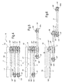
Fig. 1 represents a partly sectional side view of a closing system of a room by means of pull sliding panels according to the invention, wherein the panels are in stacked position; -
Fig. 2 is a sectional detail of the view ofFig. 1 , relating to the lower part of the panels, taken along a vertical plane orthogonal to the panels; -
Fig. 3 is an axonometric view of a portion of the group of panels ofFig. 1 ; -
Figs. 4 to 8 are sectional plan views of the panels of the system ofFig. 1 , relating to movement of the panels from the stacked position in which the opening of the room is open, to the closed position of the opening of the room; -
Fig. 9 is a sectional plan view of the panels of the system ofFig. 1 , relating to the first movement of the end closing panel from the position ofFig. 8 toward the open position; -
Fig. 10 is a sectional plan view, taken along a horizontal plane X-X, of a guiding and pulling unit of the system ofFig. 1 ; -
Fig. 11 is a a sectional side view, taken along a vertical plane XI-XI, of the guiding and pulling unit ofFig. 10 ; -
Fig. 12 is an axonometric view of the guiding and pulling unit ofFig. 10 ; -
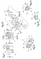
Fig. 13 is an exploded axonometric view of the guiding and pulling unit ofFig. 10 , oriented in the opposite direction with respect toFig. 12 ; -
Fig. 14 is an axonometric view of an abutment element for pulling contiguous panels of the system according to the preceding figures; -
Fig. 15 is a sectional plan view, taken along a horizontal plane, of the abutment element ofFig. 14 ; -
Fig. 16 is a axonometric view from below of two contiguous panels in a system according to the preceding figures, highlighting a guiding and pulling unit and an abutment element coupled together; -
Fig. 17 is a partly sectional front view of a first guiding and pulling unit according to the preceding figures, of a further guiding and pulling unit and of an abutment element, the last two show partly schematized with broken lines and adapted to abut with the first unit for the pulling steps, in one or other direction, of the panel with which this first unit is associated; -
Figs. 18 to 21 show four different configurations of systems according to the invention, in which different stacking cavities, and versions with different numbers of panels, can be seen. - With reference to the aforesaid figures, a closing system of a room by means of pull sliding panels is indicated as a whole with the
number 10. - In this example, the
system 10 is provided with a series of threepanels 11, indicated respectively with 11', 11 ", and 11'"; hereinafter, elements associated with a specific panel shall also be indicated with a corresponding number of apostrophes; when features associated with a panel are indicated without apostrophes, this means that they can concern all the panels, unless otherwise apparent from the context. Thesepanels 11 slide parallel to one another from a first stacked position, as shown inFigs. 1, 2, 3 and4 , to a second position, for closing the opening of a room, as shown inFig. 8 the opening for access to the room is not explicitly indicated in the figures; more generally, the "closed position of the room" will be indicated hereinafter; the jamb against which the panels abut when closed is indicated with the letter S inFigs. 7, 8 and 9 . - The
panels 11 are made, for example, of sheets, preferably flat and preferably of the same width, height and thickness. Width is intended as the dimension orthogonal to the vertical extension of the sheet when positioned upright, hereinafter referred to as "height". Hereinafter, the term sheet or the term panel shall be used at times to indicate the same object. - In this example, the sheets are made of glass or crystal. It is clear that in other examples these sheets can be made of any other material, for example wood, marble, resin, plastic, combinations of these, etc.
- Advantageously, in preferred embodiments, in the stacked position, the sheets are superimposed frontally, with the outer edges, indicated with 12A, which are substantially aligned, as clearly visible in
Fig. 3 and inFig. 4 . Therefore, alignment takes place along a line L orthogonal to the plane of the sheets or to the direction of their movement. Hereinafter, the term inner edge, indicated with 12B, is intended as the edge of the sheets, i.e. the face of the sheet related to the thickness, facing the stacked position, i.e. the edge of the sheets that during movement from the closed position to the stacked position reaches the stacked position first. The termouter edge 12A is therefore intended as the opposite edge of the sheets, i.e. the edge facing the direction of closing of the room. - Preferably, when in the stacked position, the panels are contained inside a
cavity 13. In this example, thecavity 13 is formed by a single concealingwall 13A, for example formed by a static sheet fixed to the ceiling and to the floor by means of aframe 13B. Thecavity 13 is therefore open on the side opposite thestatic sheet 13A with respect to thepanels 11, and on the side relating to the area from which thepanels 11 exit from this cavity. - As an example example, the area from which the
sheets 11 exit from thecavity 13 coincides approximately with the plane of alignment of theouter edges 12A of the sheets, coinciding in turn with theouter edge 13C of thestatic sheet 13A, as shown inFig. 4 . In other embodiments, theouter edges 12A of the sheets can be inside thecavity 13, or outside the cavity. - In other embodiments, this cavity can be closed on both sides of the panels, for example by two static sheets, as shown in the example of
Fig. 19 . In other examples, thecavity 13 can be produced close to a structural element, a masonry wall (such as the example ofFig. 21 ), a plasterboard wall, etc. - Each panel is supported by at least one trolley 14 (more preferably at least two trolleys), arranged sliding on a
respective track 15, for example fixed to aceiling 16 opposite afloor 17. Thepanels 11 are thus hung from thetrolleys 14. In practice, tracks 15 andtrolleys 14 are longitudinal sliding means for thepanels 11. - In the example of
Fig. 1 , the system is provided with a series of threepanels 11. In a known manner, the system provides that from the stacked position, a first panel 11', corresponding to the one that will be the end closing panel of the room, is moved toward the closed position. This first panel 11' translates (Fig. 5 ), and during its translation, when it is extracted for the majority of its width from thecavity 13, by means of striker means described hereinafter, "couples" asecond panel 11 ", contiguous thereto, pulling this with it (Fig. 6 ). - Similarly, the
second panel 11 ", which is an intermediate panel in the series of panels of which the system is composed, in its translation (Fig. 6 ), when it is extracted for the majority of its width from thecavity 13, by means of striker means, couples the third intermediate panel 11'", pulling this with it (Fig. 7 ). When the third panel 11'" is also extracted for the majority of its width from of thecavity 13, the room is closed, i.e. the closed position (Fig. 8 ) has been reached. As already stated, hereinafter elements associated with the first panel will also be indicated with an apostrophe, elements associated with the second panel with two apostrophes, and elements associated with the third panel with three apostrophes. - Hereinafter, the second
intermediate panel 11" is also defined intermediate panel that follows (or following) the end closing panel 11' during movement, or intermediate panel that precedes the third intermediate panel 11'" during movement. Therefore, the first panel 11' precedes the secondintermediate panel 11". Similarly, during the closing movement, the third intermediate panel 11'" is also defined panel that follows (or following) the second intermediate panel. In practice, the panel that is pulled is a panel following the panel that pulls, while the panel that pulls is the panel that precedes the panel pulled thereby. - The aforesaid striker means, which allow pulling of a panel by the panel that precedes it during the closing movement, are provided with
abutment elements 18R-19R for pulling contiguous panels, better described hereinafter, fixed in proximity of the two edges, outer 12A and inner 12B, of each panel, with the exception of theinner edge 12B'" of the last panel, i.e. the third intermediate panel 11'", clearly visible inFigs. 4 to 9 . - Moreover, there are also present, for the second
intermediate panel 11" and the third intermediate panel 11'", respective guiding and pulling units, numbered respectively with 20" and 20"', fixed in proximity of the respectiveouter edges 12A. Each unit 20 (i.e. 20" and 20'") comprises a portion of slidingguide 21 for thelower edge 12C of the panel that precedes the closing movement of the room (panel that precedes: i.e. the first end closing panel 11' in the case of theunit 20", or the secondintermediate panel 11" in the case of theunit 20"'). Moreover, eachunit 20 also comprises counter abutment portions 22 (clearly visible inFigs. 13 and17 ) for theabutment elements abutment element 19R acts by pulling during the closing movement, while theabutment element 18R acts during the opening movement). - In practice, in the movement from the stacked/open position to the closed position, the
abutment element 19R' associated with theinner edge 12B' of the end closing panel 11' that precedes the secondintermediate panel 11" (intermediate panel 20" to theouter edge 12A" of which the guiding and pullingunit 20" is fixed) abuts against the counter abutment portion 22 (better described below) of theunit 20", pulling this with it, and therefore pulling with it the whole secondintermediate panel 11 "(figure 5, 6 and16 ). With sliding of the secondintermediate panel 11 ", therespective abutment element 19R" associated with theinner edge 12B" of this panel, encounters thecounter abutment portion 22 of the unit 20'" fixed to theouter edge 12A'" of the third intermediate panel 11'", pulling this latter with it until the closed position (Figs. 6 ,7 ,8 and17 ) is reached. - On the contrary, in the movement from the closed position to the stacked/open position, the
abutment elements 18R associated with the outer edges of the preceding panels, impact in sequence against the secondcounter abutment portions 22 of the panels that follow, pulling with them the intermediate panels that follow toward the opening. - Advantageously, the
system 10 can be provided with aguide 23, to be fixed to thefloor 17, in which there is arranged slidingly the last panel of the series (i.e. the last panel to be pulled into the closed position during the closing movement), that is, in this example, the third intermediate panel 11'" of said series of panels. Preferably, thisguide 23 is of a length that is less than the width of this latter panel 11'". Even more preferably, thisguide 23 is completely contained in thecavity 13, for example aligned with itsouter end 23A with theouter edge 13C of thestatic sheet 13A (i.e. with theedges 12A of the panels 11). In this example, theguide 23 has a U-shaped cross section. - Preferably, the guiding and pulling unit 20 (see, for example,
Figs. 10, 11, 12 and 13 , in which thesheet 11 is not visible) comprises asandwich locking portion 24 to theouter edge 12A of theintermediate panel 11 to which it is fixed, formed by aplate 24A and acounter plate 24B arranged on opposite sides of thesheet 11, and ascrew 24C for connection of the plate and of the counter plate, passing through this sheet. Theplate 24A has a shapedpart 24D adapted to abut against theouter edge 12A of thesheet 11, which also allows theunit 20 correct to maintain the correct orientation with respect to both theedges - Advantageously, in preferred embodiments, the guiding and pulling
unit 20 also comprises theaforesaid abutment element 18R related to theouter edge 12A. For example, from one side of thesandwich locking portion 24 there extends an appendage that forms thisabutment element 18R. For example, this appendage, also numbered with 18R for simplicity, extends from thecounter plate 24B. - Preferably, on the side of the locking
portion 24, opposite theappendage 18R with respect to thepanel 11, there is defined, at a distance F from thelower edge 12C of thepanel 11 substantially corresponding to the distance of theappendage 24 from thislower edge 12C, a pair ofseats 25, open in opposite directions toward the opening or closing direction of the panels, for receiving arespective appendage seats 25 there are defined respectivecounter abutment portions 22 for theabutment elements - Advantageously, the guiding and pulling
unit 20 also comprises, on the same side of thepanel 11 in which theseats 25 are present, theportion 21 of sliding guide for the panel that precedes in movement, as described above. - Preferably, in the guiding and pulling
unit 20, theseats 25, theguide portion 21 and at least part of said locking portion, for example, theplate 24A, are produced in a single piece. - With particular reference to
figure. 2 , it can be noted how, preferably, the lockingportion 24 has a distance D (for example measured from the lowest point of thecounter plate 24B) from thelower edge 12C of thepanel 11 at least equal to or greater than the depth P of the guide portion (for example measured vertically from the bottom of the guide portion to the horizontal projection of the lowest point of the same point of the lockingportion 24 from which the distance D from thelower edge 12C was measured). - The
guide portion 21 is lower than theseats 25 and is preferably projecting laterally therefrom (in practice, it projects laterally and downward). Thisguide portion 21 has, for example, aguide cavity 21 A with U-shaped cross section. - According to the description above, it is clear that there are present two guiding and pulling
units 20" and 20"', fixed in proximity of the respectiveouter edges 12A" and 12A'" of the secondintermediate panel 11" and thirdintermediate panel 11"' (last panel of the series to be pulled toward the closed position). It should be noted that the figures show anappendage 18R"', i.e. projecting from the third guiding and pullingunit 20"', which has no practical function, as it does not require to abut against anything, but is provided purely for aesthetic purposes and industrial convenience (besides having the practical use of serving as a threaded seat to tighten thescrew 24C and lock the unit 20). - In the case in which the panels are two in number (as in
Fig. 18 ), there will be present a single guiding and pullingunit 20", on the secondintermediate panel 11" (the same reference numbers as in the preceding case are maintained); also in this case theappendage 18R" is provided purely for aesthetic purposes and industrial convenience. - In the case of more than three panels, for example five panels, as in
Fig. 20 ., there are present four guiding and pullingunits 20", 20"', 20IV and 20V, for fourrespective panels 11", 11"', 11IV and 11V (last panel); also in this case theappendage 18RV is provided purely for aesthetic purposes and industrial convenience (besides having, as already mentioned, the practical use of serving as a threaded seat to tighten thescrew 24C and lock the unit 20). - Generalizing, it can be said that given a number n of panels (with a minimum of two sliding panels), there will be present n-1 guiding and pulling
units 20. - The
abutment elements 19R are preferably in the form of appendages that project laterally fromabutment units 26 fixed at theinner edges 12B of the panels (with the exclusion of the last panel to be pulled, in the case of three panels, the thirdintermediate panel 11"'). These appendages, also numbered with 19R for simplicity, are preferably identical to theappendages 18R. Each abutment unit 26 (see for exampleFigs. 14 and 15 , in which thesheet 11 is not represented) has a further sandwich locking portion 24bis which comprises, similarly to the case of the guiding and pullingunits 20, for example afurther plate 24a and afurther counter plate 24b arranged on opposite sides of the respective sheet, and afurther screw 24c for connection of said plate and counter plate passing through said sheet. Also in this case, thefurther plate 24a has a further shapedpart 24d adapted to abut against theinner edge 12A of thesheet 11. Theappendage 19R projects from thefurther counter plate 24b. - Similarly, only for the first panel 11', there is present a further abutment unit 26bis, similar to the abutment unit 26', arranged in proximity of the
outer edge 12A' of the panel, substantially at the same height and position as the abutment unit 26'. - Now, as stated, the
abutment elements counter abutment portions 22 of the guiding and pullingunits 20. The appendages that form theabutment elements elastic ring 27, for example an O-ring, made of rubber or other similar material. When theappendages seats 25 and abut against thecounter abutment portions 22, advantageously there is present a reversible coupling between them, so that there is a certain degree of tightness between abutment appendage andrelated seat 25. This reversible coupling takes place through the elastic deformation of the ring. - Advantageously, each
opposed seat 25 has a concave configuration, for example C-shaped, with dimensions such as to urge theelastic ring 27 to temporarily deform by compression during the step of inserting the appendage into the seat; when the appendage is inserted into the seat, the shape of this urges this appendage to remain in position; the step of removal of the appendage from the seat takes place simply with a thrust, in the opening direction of the seat, such as to overcome the elastic deformation of the ring. - It can be noted how in
Figs. 13 and17 , the twoopposed seats 25 are shaped like a C without the back, i.e. the seat, on the top and on the bottom, has two opposed cusps that define thecounter abutment portions 22. The space between the two cusps would correspond to back part of the C-shape seat. According to another point of view, each seat is formed by two opposedconcave portions 25a, defined on the top and on the bottom, facing each other, one side of which is produced by the cusps defining thecounter abutment portions 22. - As stated before, the
outer edges 12A are preferably aligned with one another along L. In other embodiments, theouter edges 12A may not be aligned. For example, in certain cases, it may be useful to fix a handle to the first panel 11' and therefore the outer edge of the first panel must protrude slightly with respect to the outer edges of the other panels (which can be aligned with one another); In this case, it will be necessary to fix theabutment element 18R' at a greater distance from theouter edge 12A' with respect to the distance related to the case of alignment (i.e. a greater distance with respect to the distance of therelated seat 25 from theouter edge 12A" of thesecond panel 11 "). - Operation of the system is as follows. With reference to the stacked/closed position, in which all the panels are aligned with their
outer edge 12A on the line L (Fig. 4 ). The first panel 11' has theappendage 18R' of the abutment unit 26bis inserted in theseat 25 of the guiding and pullingunit 20" fixed to thesecond panel 11 "; similarly, thesecond panel 11" has theappendage 18R" projecting from its guiding and pullingunit 20" inserted in theseat 25 of the guiding and pulling unit 20'" fixed to the third panel 11'". Thelower edge 12C' of the first panel 11' is inserted in theguide portion 21" of the guiding and pullingunit 20" fixed to thesecond panel 11 ", just as thelower edge 12C" of thesecond panel 11" is inserted in the guide portion 21'" of the guiding and pulling unit 20'" fixed to the third panel 11'". Thelower edge 12C'" of the third and last panel 11'" is inserted in thefloor guide 23. - The user starts to push the first panel 11' toward the closed position, overcoming the slight resistance for elastic deformation (viscoelastic or similar) of the
ring 27 on theseat 25 of the guiding and pullingunit 20", so that theappendage 18R' of the abutment unit 26bis is removed from theseat 25. The panel 11' thus slides with itslower edge portion 12C' (Fig. 5 ) inside theguide portion 21" of the guiding and pullingunit 20". At a certain point, theappendage 19R' of the abutment unit 26' of the first panel 11' is inserted in theseat 25 of the guiding and pullingunit 20" of thesecond panel 11 ", deforming itsring 27 and abutting against thecounter abutment portion 22 of the guiding and pullingunit 20". - Continuing translation of the first panel 11', the
second panel 11" also starts to translate toward the closed position (Fig. 6 ). Thesecond panel 11" slides with itslower edge portion 12C" inside the guide portion 21'" of the guiding and pullingunit 20"'. - At a certain point, the
appendage 19R" of the guiding and pullingunit 20" of thesecond panel 11" is inserted in theseat 25 of the guiding and pulling unit 20'" of thethird panel 11"', deforming itsring 27 and abutting against thecounter abutment portion 22 of the guiding and pullingunit 20"'. Continuing translation of the first panel 11', thethird panel 11"' also starts to translate toward the closed position (Fig. 7 ). The third panel 11'" slides with itslower edge portion 12C'" inside thefloor guide 23. When theouter edge 12A' of the first panel 11' reaches the jamb S, the closed position of the room is reached. In this position, the third panel 11'" is still inside the floor guide 23 (Fig. 8 ). - From the closed position, the user can push the first panel 11' toward the stacked position; by doing this, the slight resistance of the
seat 25 of the second guiding and pullingunit 20" on thering 27 of theabutment element 19R' of the abutment unit 26' is overcome. At this point the first panel 11' slides in theguide portion 21" of the guiding and pullingunit 20" of thesecond panel 11" (still not moving) (Fig. 9 ) until theabutment element 18R' of the abutment unit 16bis is inserted in theseat 25 of the second guiding and pullingunit 20", abutting against thecounter abutment portion 22 and thereby also translating thesecond panel 11". The movement continues in the same way until all the panels return inside thecavity 13. - From a practical point of view, in the case of use of
abutment elements 18R-19R that reversibly couple with the counter abutment portions (for example appendages withrings 27 coupled with the seats 25), the order in which the panels detach from one another, both in the closing movement of the room, and in the opening/stacking movement, can be random (in practice depending on the force required for the panels to "detach" from one another). - For example, in the case of three panels, during opening of the room, the user can pull the first panel 11' and this, instead of immediately detaching from the
second panel 11" translating with respect thereto, can immediately move the second panel (in practice, the first and the second panel still move together with the two panels not superimposed). At this point the second panel can immediately separate from the third panel 11'", with the first panel-second panel assembly translating in relation to the third panel (with this the movement of the panels then follows the movement described above, i.e. the second panel which abuts on the third panel, becoming aligned with this in stacked position and the first panel that starts to translate with respect to the second panel, returning inside the cavity), or the second panel can remain beside the third panel, while the first panel detaches from the second, moving in relation to the second-third panel assembly, as in the case described above. The same can take place in the case of the movement to close the room, i.e. during movement of the first panel, for example, the second panel can immediately move together with it (i.e. superimposed with the outer edges aligned), subsequently pulling the third panel. The "detachment" combinations of the panels can be many. In practice, the order of "detachment" of the panels can be random, although naturally all following the movement of the first panel. - In general, a limit stop (not shown in the figures) can be present for the last panel of the system, when arranged to close, together with the other panels, the room, preferably arranged on the upper track, in which the related trolley slides. This stop identifies the closed position of the last panel, beyond which it can no longer move forward. Advantageously, a limit stop (not shown in the figures) can also be present in the stacked position of the last panel, so as to prevent it from being inserted into the
cavity 13 beyond this position. More in general, limit stops can be present in the related closing position of the room and stacking position for each panel of the system. - The invention also relates to a kit for assembly of a closing system of a room by means of pull sliding panels according to one or more of the possible embodiments indicated above, which comprises at least the
abutment elements contiguous panels 11, to be fixed in proximity of twoedges intermediate panel 11' and 11". - Preferably, the kit comprises, for a system that comprises a number "n" of sliding panels, "n-1"
abutment units 26 to be fixed in proximity of theinner edge 12B of the panels, with the exclusion of the last panel "n", an abutment unit 26bis to be fixed to theouter edge 12A' of the end closing panel 11', and "n-1" guiding and pullingunits 20 to be fixed to theouter edge 12A of the panels with the exclusion of the first panel 11'; preferably the system is also provided with afloor guide 23 for thelast panel 11n. - The system and the related kit thus described achieve the set objects. In fact, through the abutment elements positioned in the lower part of the panels, the outer edges of the panels can be maintained aligned with one another when in stacked position. Moreover, with this configuration, the risks of malfunction of the system are very low and maintenance of the system is facilitated.
- Further, the panels are properly guided during their travel, eliminating the effect of pivoting about the upper track in which the trolleys from which the panels are hung slide.
- In addition, the abutment method of the abutment elements and of the counter abutment portions makes it possible to ensure the stability of the positions of the panels even in the presence of small imprecisions in the horizontality of the sliding system of the panels, while at the same time minimizing the noise in movement of the panels.
- It is understood that the drawings only show possible non-limiting embodiments of the invention, which can vary in form and arrangement without however departing from the scope of the concept on which the invention is based. Any reference numerals in the appended claims are provided purely for the purpose of facilitating the reading thereof in the light of the description above and of the accompanying drawings, and do not in any way limit the scope of protection.
Claims (20)
- A closing system (10) of a room by means of pull sliding panels, comprising:- a series of at least two panels (11) sliding parallel to one another from a first stacked/open position in which they are substantially superimposed frontally, to a second closed position for closing a room in which the panels (11) are moved apart from one another, and vice versa, there being comprised in said series at least one intermediate panel (11 ", 11"') and one end closing panel (11') for closing the room that precedes said at least one intermediate panel during movement,- longitudinal sliding means (14, 15) for said panels (11), arranged above said panels, from which said panels (11) are hung,- abutment elements (18R, 19R) for pulling contiguous panels, fixed in proximity of the two edges (12A, 12B), outer and inner, at least of said end closing panel (11') and/or of one intermediate panel (11 "),- at least one guiding and pulling unit (20) fixed in proximity of the outer edge (12A) of said at least one intermediate panel (11 ", 11'"), defined as following intermediate panel, comprisingso that in the movement from the stacked/open position to the closed position, the abutment element (19R', 19R") associated with the inner edge of said end panel (11') or of said intermediate panel (11 ") that precedes said following intermediate panel (11'"), impacts against a first said counter abutment portion (22) of said following intermediate panel (11 ", 11'"), pulling with it said following intermediate panel (11 ", 11'"), while, in the movement from the closed position to the stacked/open position, the abutment element (18R', 18R") associated with the outer edge of said end panel (11') or with said intermediate panel (11 ") that precedes it, impacts against the second counter abutment portion of said following intermediate panel (11 ", 11'"), pulling with it the same following intermediate panel (11 ", 11"') toward the closed position.o a portion (21) of sliding guide for the sliding of the lower edge (12C) of said end panel (11') or of an intermediate panel (11 ") that precedes, in movement, said following intermediate panel (11'"), ando counter abutment portions (22) for said abutment elements (18R', 19R') of said end panel (11') or for abutment elements (18R", 19R") of said intermediate panel (11 ") which precedes said following intermediate panel (11'") in movement,
- The closing system of a room according to claim 1, wherein the outer edges (12A) of said panels (11) are substantially aligned when the panels (11) are in said stacked position.
- The closing system of a room according to claim 1 or 2, comprising a guide (23) to be fixed to the floor in which there is arranged slidingly the last panel (11"') of said series of panels, i.e. the last panel to be pulled in closed position during the closing movement.
- The closing system of a room according to claim 3, wherein the length of said guide (23) is less than the width of said last panel (11"').
- The closing system of a room according to one or more of the preceding claims, wherein said panels (11) in said stacked position, are contained inside a cavity (13), preferably with the outer edges (12A) of said panels substantially aligned with one another and with the edge (13C) of said cavity (13).
- Closing system of a room according to claims 3 and 5, wherein said guide (23) is contained completely in said cavity (13).
- Closing system of a room according to one or more of the preceding claims, wherein said at least one guiding and pulling unit (20) comprises a sandwich locking portion (24) to the outer edge (12A) of the intermediate panel (11", 11'"), from one side of said locking portion (24) there extends an appendage forming a said abutment element (18R"), on the side of said locking portion (24), opposite said appendage (18R", 18R'") with respect to the panel (11 "), there being defined, at a distance (D) from the lower edge (12C) of the panel substantially corresponding to the distance of the appendage (18R", 18R'") from said lower edge (12C), a pair of seats (25) open in opposite directions toward the opening or closing directions of the panels, for receiving a respective said appendage (18R, 19R), in which there are defined respective said counter abutment portions (22) for the abutment elements (18R, 19R) of the panel that precedes in movement; said guiding and pulling unit (20) comprising, on the same side of the panel in which said seats (25) are present, said portion (21", 21'") of sliding guide for the panel (11', 11 ") that precedes in movement.
- Closing system of a room according to claim 7, wherein said locking portion (24) has a distance (P) from the lower edge (12C) of the panel at least equal to or greater than the depth of said guide portion (21); said guide portion (21) being below said seats (25) and projecting laterally therefrom.
- Closing system of a room according to claim 7 or 8, wherein said sandwich locking portion (24) comprises a plate (24A) and a counter plate (24B) arranged on opposite sides of said panel (11), and a screw (24C) for connection of said plate and counter plate passing through said panel.
- Closing system of a room according to claim 7, 8 or 9, wherein, in said guiding and pulling unit (20), said seats (25), said guide portion (21) and at least part of said locking portion (24) form a single piece.
- Closing system of a room according to one or more of claims 7 to 10, wherein said abutment elements (18R', 19R', 18R", 19R") for pulling contiguous panels, fixed in proximity of the two edges (12A', 12B'), outer and inner, of said end closing panel (11') and of the inner edge (12B") of said at least one intermediate panel (11") comprise a said appendage adapted to associate with said counter abutment portions (22) of a said guiding and pulling unit (20", 20'") of the contiguous intermediate panel.
- Closing system of a room according to one or more of the preceding claims, wherein there are associated with said end closing panel (11') two abutment units (26bis, 26') each comprising a said abutment element (18R', 19R'); said abutment units (26bis, 26') comprising respective sandwich locking portions (24bis) to the panel (11'); preferably, said locking portions (24bis) comprising a plate (24a) and a counter plate (24b) arranged on opposite sides of said panel (11), and a screw (24c) for connection of said plate and counter plate passing through said panel (11').
- Closing system of a room according to one or more of the preceding claims, wherein there is associated with at least one said intermediate panel (11 ") a said guiding and pulling unit (20") fixed in proximity of the outer edge (12A") and, in the case in which said intermediate panel is not the last panel of the series, also an abutment unit (26") comprising at least one said abutment element (18R"); said abutment unit (26") comprising a said sandwich locking portion (24") to the inner edge (12B") of said panel (11"); preferably said locking portion comprising a plate and a counter plate arranged on opposite sides of said sheet, and a connection screw of said plate and counter plate passing through said panel.
- Closing system of a room according to one or more of the preceding claims, wherein there is present a reversible coupling between said abutment element (18R, 19R) and the related counter abutment portion (22); preferably said reversible coupling being of the type for elastic deformation.
- Closing system of a room according to claims 7 and 13, wherein said appendage (18R, 19R) is surrounded by an elastic ring (27), preferably made of rubber or the like; said seat (25) having a concave configuration, preferably C-shaped, with dimensions such as to urge the elastic ring (27) to temporarily deform by compression during the step of inserting the appendage into said seat (25); said seat urging said appendage into position when it is inserted therein; the step of removal of the appendage from the seat occurring with a thrust such as to overcome the deformation of the ring (27) for removal from the seat (25).
- Closing system of a room according to one or more of the preceding claims, wherein said longitudinal sliding means for said panels comprise tracks (15) arranged above said panels (11), and trolleys (14) from which said panels are hung, sliding in said tracks.
- Closing system of a room according to one or more of the preceding claims, wherein said panels are made of glass or crystal.
- Closing system of a room according to one or more of the preceding claims, wherein said series of panels (11) comprises at least a first panel (11') and a second panel (11 "), with said first panel (11'), for closing the end of the room, which precedes the second panel (11 ") during movement; said abutment elements (18R', 19R') for pulling contiguous panels being fixed in proximity of the two edges (12A', 12B'), outer and inner, of at least said first end closing panel (11'); said at least one guiding and pulling unit (20") being fixed in proximity of the outer edge (12A") at least of said second panel (11"), said guiding and pulling unit (20") comprising a portion (21 ") of sliding guide for the lower edge (12C') of said first panel (11'), and counter abutment portions (22) for said abutment elements (18R', 19R') of said first panel (11'), so that in the movement from the stacked /open position to the closed position, the abutment element (19R') associated with the inner edge (12B') of the first panel (11') that precedes the second panel (11") in movement, impacts against a first said counter abutment portion (22) associated with the guiding and pulling unit (20") of the second panel (11 ") which follows, pulling with it this second panel, while, in the movement from the closed position to the stacked/open position, the abutment element (18R') associated with the outer edge (12A') of the first panel (11') impacts against the second counter abutment portion (22) of the guiding and pulling unit (20") of the second panel (11 "), pulling this with it.
- The closing system of a room according to one or more of the preceding claims, which comprises at least three panels (11', 11 ", 11'"); of said at least three panels there are present a last panel (11'") adapted to close the room on the opposite side thereof with respect to the first panel (11'), and a second last panel (11 ") that precedes the last panel (11 "); in proximity of the inner and outer edges (12B", 12A") of the second last panel (11") there are associated said abutment elements (18R", 19R") for pulling contiguous panels (11', 11'"); there being associated with said last panel (11'") at least one said guiding and pulling unit (20'") fixed in proximity of the outer edge (12A'") of the last panel (11'"), which comprises a portion (21) of sliding guide for the lower edge (12C'") of the second last panel, and counter abutment portions (22) for abutment elements of the second last panel (18R", 19R"); the system is such that in the movement from the stacked/open position to the closed position, the abutment element (19R") associated with the inner edge (12B") of the second last panel (11 ") that precedes the last panel (11'") in movement, impacts against a first counter abutment portion (22) of the guiding and pulling unit (20'") associated with the last panel (11'") that follows, pulling with it said last panel (11'"), while, in the movement from the closed position to the stacked/open position, the abutment element (18R") associated with the outer edge (12A") of the second last panel (11") impacts against the second counter abutment portion (22) of the guiding and pulling unit (20"') associated with the last panel (11'"), pulling this with it.
- A kit for assembly of a closing system of a room by means of pull sliding panels according to one or more of the preceding claims, comprising at least- said abutment elements (18R, 19R) for pulling contiguous panels, to be fixed in proximity of the two edges (12A, 12B), outer and inner, at least of said end closing panel (11') and/or of one intermediate panel (11 ", 11'"),- said at least one guiding and pulling unit (20) to be fixed in proximity of the outer edge (12A) of said at least one intermediate panel (11 ", 11"').
Applications Claiming Priority (1)
| Application Number | Priority Date | Filing Date | Title |
|---|---|---|---|
| IT000087A ITFI20130087A1 (en) | 2013-04-22 | 2013-04-22 | "SYSTEM FOR CLOSING A COMPARTMENT BY DRIVING SLIDING DOORS AND ASSEMBLY KIT FOR SUCH SYSTEM" |
Publications (1)
| Publication Number | Publication Date |
|---|---|
| EP2796649A1 true EP2796649A1 (en) | 2014-10-29 |
Family
ID=48703659
Family Applications (1)
| Application Number | Title | Priority Date | Filing Date |
|---|---|---|---|
| EP20140165321 Withdrawn EP2796649A1 (en) | 2013-04-22 | 2014-04-18 | Closing system of a room by means of pull sliding panels and kit for assembly of said system |
Country Status (2)
| Country | Link |
|---|---|
| EP (1) | EP2796649A1 (en) |
| IT (1) | ITFI20130087A1 (en) |
Cited By (2)
| Publication number | Priority date | Publication date | Assignee | Title |
|---|---|---|---|---|
| EP3045630A1 (en) * | 2015-01-14 | 2016-07-20 | DORMA Deutschland GmbH | Guiding device for the guiding a door leaf of a sliding door |
| EP3211162B1 (en) * | 2016-02-23 | 2026-04-08 | Gebr. Willach GmbH | Sliding door system |
Citations (2)
| Publication number | Priority date | Publication date | Assignee | Title |
|---|---|---|---|---|
| US2833346A (en) * | 1956-01-30 | 1958-05-06 | Acme Appliance Mfg Company | Sliding door assembly |
| US7458410B1 (en) * | 2003-11-28 | 2008-12-02 | Dan Bronner | Multiple door joining assembly |
-
2013
- 2013-04-22 IT IT000087A patent/ITFI20130087A1/en unknown
-
2014
- 2014-04-18 EP EP20140165321 patent/EP2796649A1/en not_active Withdrawn
Patent Citations (2)
| Publication number | Priority date | Publication date | Assignee | Title |
|---|---|---|---|---|
| US2833346A (en) * | 1956-01-30 | 1958-05-06 | Acme Appliance Mfg Company | Sliding door assembly |
| US7458410B1 (en) * | 2003-11-28 | 2008-12-02 | Dan Bronner | Multiple door joining assembly |
Cited By (3)
| Publication number | Priority date | Publication date | Assignee | Title |
|---|---|---|---|---|
| EP3045630A1 (en) * | 2015-01-14 | 2016-07-20 | DORMA Deutschland GmbH | Guiding device for the guiding a door leaf of a sliding door |
| EP3045630B1 (en) | 2015-01-14 | 2022-06-15 | DORMA-Glas GmbH | Guiding device for the guiding a door leaf of a sliding door |
| EP3211162B1 (en) * | 2016-02-23 | 2026-04-08 | Gebr. Willach GmbH | Sliding door system |
Also Published As
| Publication number | Publication date |
|---|---|
| ITFI20130087A1 (en) | 2014-10-23 |
Similar Documents
| Publication | Publication Date | Title |
|---|---|---|
| US8528255B2 (en) | Outward opening window unit | |
| US3744827A (en) | Hardware for a sliding door installation | |
| US11828095B2 (en) | Sliding door system capable of inline closure and capable of use with corner openings | |
| EP3094801B1 (en) | Sliding door with magnetic support | |
| US8453703B2 (en) | Self-storing vertical lift door system | |
| CN104704184A (en) | Shower door track corner connecting device, shower door frame, and shower door | |
| US20110072613A1 (en) | Spring biased roller for a shower door or the like | |
| EP2796649A1 (en) | Closing system of a room by means of pull sliding panels and kit for assembly of said system | |
| US8955254B1 (en) | Self-storing security door assembly | |
| JP2019002275A (en) | Joinery construction structure | |
| RU2490402C2 (en) | Structure to separate rooms | |
| US20060168894A1 (en) | Pre-fabricated sliding door assembly | |
| CN106320628B (en) | A kind of flat hanging plate of modeling wood and its installation and connection method and installation connecting element | |
| US11873677B2 (en) | Fenestration system with actuatable sealing device, and related devices, systems, and methods | |
| US9845626B2 (en) | Removable window sash system with integrated spring biased retainer | |
| CN104574604B (en) | Intelligent building door control system containing rolling balls | |
| RU155874U1 (en) | GUIDE PROFILE | |
| GB2490574A (en) | Portable temporary door lock | |
| US7461908B1 (en) | Cabinet locking system | |
| CN208416374U (en) | A kind of anti-theft type aluminum-coated wood window | |
| GB2480616A (en) | Secondary glazing system | |
| AU2024264672A1 (en) | A Shower Recess and Kit | |
| CN203515233U (en) | Adsorption-type shockproof door | |
| EP3779113A1 (en) | Door/window with fixed wing for outdoors settings | |
| CN117905363A (en) | Frameless door plate assembly and assembly type wallboard hidden door |
Legal Events
| Date | Code | Title | Description |
|---|---|---|---|
| PUAI | Public reference made under article 153(3) epc to a published international application that has entered the european phase |
Free format text: ORIGINAL CODE: 0009012 |
|
| 17P | Request for examination filed |
Effective date: 20140418 |
|
| AK | Designated contracting states |
Kind code of ref document: A1 Designated state(s): AL AT BE BG CH CY CZ DE DK EE ES FI FR GB GR HR HU IE IS IT LI LT LU LV MC MK MT NL NO PL PT RO RS SE SI SK SM TR |
|
| AX | Request for extension of the european patent |
Extension state: BA ME |
|
| R17P | Request for examination filed (corrected) |
Effective date: 20150429 |
|
| RBV | Designated contracting states (corrected) |
Designated state(s): AL AT BE BG CH CY CZ DE DK EE ES FI FR GB GR HR HU IE IS IT LI LT LU LV MC MK MT NL NO PL PT RO RS SE SI SK SM TR |
|
| GRAP | Despatch of communication of intention to grant a patent |
Free format text: ORIGINAL CODE: EPIDOSNIGR1 |
|
| RIC1 | Information provided on ipc code assigned before grant |
Ipc: E05D 15/08 20060101AFI20150828BHEP Ipc: E05F 17/00 20060101ALI20150828BHEP |
|
| INTG | Intention to grant announced |
Effective date: 20150922 |
|
| STAA | Information on the status of an ep patent application or granted ep patent |
Free format text: STATUS: THE APPLICATION IS DEEMED TO BE WITHDRAWN |
|
| 18D | Application deemed to be withdrawn |
Effective date: 20160203 |