EP2802062A1 - Elektrischer Generator für einen Windkraftgenerator - Google Patents
Elektrischer Generator für einen Windkraftgenerator Download PDFInfo
- Publication number
- EP2802062A1 EP2802062A1 EP13002449.0A EP13002449A EP2802062A1 EP 2802062 A1 EP2802062 A1 EP 2802062A1 EP 13002449 A EP13002449 A EP 13002449A EP 2802062 A1 EP2802062 A1 EP 2802062A1
- Authority
- EP
- European Patent Office
- Prior art keywords
- stator
- electric generator
- rotatable support
- rotor
- magnetic
- Prior art date
- Legal status (The legal status is an assumption and is not a legal conclusion. Google has not performed a legal analysis and makes no representation as to the accuracy of the status listed.)
- Withdrawn
Links
- 230000005291 magnetic effect Effects 0.000 claims abstract description 49
- 239000003302 ferromagnetic material Substances 0.000 claims abstract description 3
- 238000004804 winding Methods 0.000 claims description 20
- RYGMFSIKBFXOCR-UHFFFAOYSA-N Copper Chemical compound [Cu] RYGMFSIKBFXOCR-UHFFFAOYSA-N 0.000 claims description 5
- 229910052802 copper Inorganic materials 0.000 claims description 5
- 239000010949 copper Substances 0.000 claims description 5
- OKTJSMMVPCPJKN-UHFFFAOYSA-N Carbon Chemical compound [C] OKTJSMMVPCPJKN-UHFFFAOYSA-N 0.000 claims description 2
- 229910052799 carbon Inorganic materials 0.000 claims description 2
- 239000002131 composite material Substances 0.000 claims description 2
- 239000000835 fiber Substances 0.000 claims 1
- 239000000696 magnetic material Substances 0.000 claims 1
- 239000000463 material Substances 0.000 description 6
- XEEYBQQBJWHFJM-UHFFFAOYSA-N Iron Chemical group [Fe] XEEYBQQBJWHFJM-UHFFFAOYSA-N 0.000 description 3
- 238000001816 cooling Methods 0.000 description 3
- 239000003822 epoxy resin Substances 0.000 description 3
- 229920000647 polyepoxide Polymers 0.000 description 3
- 230000000295 complement effect Effects 0.000 description 2
- 230000004907 flux Effects 0.000 description 2
- 238000005304 joining Methods 0.000 description 2
- 238000004519 manufacturing process Methods 0.000 description 2
- 238000000034 method Methods 0.000 description 2
- 230000001681 protective effect Effects 0.000 description 2
- 238000000926 separation method Methods 0.000 description 2
- 230000015572 biosynthetic process Effects 0.000 description 1
- 239000012809 cooling fluid Substances 0.000 description 1
- 230000001419 dependent effect Effects 0.000 description 1
- 238000006073 displacement reaction Methods 0.000 description 1
- 230000001747 exhibiting effect Effects 0.000 description 1
- 230000005294 ferromagnetic effect Effects 0.000 description 1
- 238000009434 installation Methods 0.000 description 1
- 229910052742 iron Inorganic materials 0.000 description 1
- 235000000396 iron Nutrition 0.000 description 1
- 239000002648 laminated material Substances 0.000 description 1
- 238000010008 shearing Methods 0.000 description 1
- 238000004513 sizing Methods 0.000 description 1
Images


Classifications
-
- H—ELECTRICITY
- H02—GENERATION; CONVERSION OR DISTRIBUTION OF ELECTRIC POWER
- H02K—DYNAMO-ELECTRIC MACHINES
- H02K1/00—Details of the magnetic circuit
- H02K1/06—Details of the magnetic circuit characterised by the shape, form or construction
- H02K1/22—Rotating parts of the magnetic circuit
- H02K1/28—Means for mounting or fastening rotating magnetic parts on to, or to, the rotor structures
- H02K1/30—Means for mounting or fastening rotating magnetic parts on to, or to, the rotor structures using intermediate parts, e.g. spiders
-
- H—ELECTRICITY
- H02—GENERATION; CONVERSION OR DISTRIBUTION OF ELECTRIC POWER
- H02K—DYNAMO-ELECTRIC MACHINES
- H02K1/00—Details of the magnetic circuit
- H02K1/06—Details of the magnetic circuit characterised by the shape, form or construction
- H02K1/22—Rotating parts of the magnetic circuit
- H02K1/27—Rotor cores with permanent magnets
- H02K1/2793—Rotors axially facing stators
- H02K1/2795—Rotors axially facing stators the rotor consisting of two or more circumferentially positioned magnets
- H02K1/2796—Rotors axially facing stators the rotor consisting of two or more circumferentially positioned magnets where both axial sides of the rotor face a stator
-
- H—ELECTRICITY
- H02—GENERATION; CONVERSION OR DISTRIBUTION OF ELECTRIC POWER
- H02K—DYNAMO-ELECTRIC MACHINES
- H02K1/00—Details of the magnetic circuit
- H02K1/06—Details of the magnetic circuit characterised by the shape, form or construction
- H02K1/12—Stationary parts of the magnetic circuit
- H02K1/18—Means for mounting or fastening magnetic stationary parts on to, or to, the stator structures
- H02K1/182—Means for mounting or fastening magnetic stationary parts on to, or to, the stator structures to stators axially facing the rotor, i.e. with axial or conical air gap
-
- H—ELECTRICITY
- H02—GENERATION; CONVERSION OR DISTRIBUTION OF ELECTRIC POWER
- H02K—DYNAMO-ELECTRIC MACHINES
- H02K1/00—Details of the magnetic circuit
- H02K1/06—Details of the magnetic circuit characterised by the shape, form or construction
- H02K1/22—Rotating parts of the magnetic circuit
- H02K1/27—Rotor cores with permanent magnets
- H02K1/2706—Inner rotors
- H02K1/2713—Inner rotors the magnetisation axis of the magnets being axial, e.g. claw-pole type
-
- H—ELECTRICITY
- H02—GENERATION; CONVERSION OR DISTRIBUTION OF ELECTRIC POWER
- H02K—DYNAMO-ELECTRIC MACHINES
- H02K7/00—Arrangements for handling mechanical energy structurally associated with dynamo-electric machines, e.g. structural association with mechanical driving motors or auxiliary dynamo-electric machines
- H02K7/18—Structural association of electric generators with mechanical driving motors, e.g. with turbines
- H02K7/1807—Rotary generators
- H02K7/1823—Rotary generators structurally associated with turbines or similar engines
- H02K7/183—Rotary generators structurally associated with turbines or similar engines wherein the turbine is a wind turbine
-
- H—ELECTRICITY
- H02—GENERATION; CONVERSION OR DISTRIBUTION OF ELECTRIC POWER
- H02K—DYNAMO-ELECTRIC MACHINES
- H02K2201/00—Specific aspects not provided for in the other groups of this subclass relating to the magnetic circuits
- H02K2201/15—Sectional machines
-
- Y—GENERAL TAGGING OF NEW TECHNOLOGICAL DEVELOPMENTS; GENERAL TAGGING OF CROSS-SECTIONAL TECHNOLOGIES SPANNING OVER SEVERAL SECTIONS OF THE IPC; TECHNICAL SUBJECTS COVERED BY FORMER USPC CROSS-REFERENCE ART COLLECTIONS [XRACs] AND DIGESTS
- Y02—TECHNOLOGIES OR APPLICATIONS FOR MITIGATION OR ADAPTATION AGAINST CLIMATE CHANGE
- Y02E—REDUCTION OF GREENHOUSE GAS [GHG] EMISSIONS, RELATED TO ENERGY GENERATION, TRANSMISSION OR DISTRIBUTION
- Y02E10/00—Energy generation through renewable energy sources
- Y02E10/70—Wind energy
- Y02E10/72—Wind turbines with rotation axis in wind direction
Definitions
- the present invention relates to an electric generator for a wind power generator also known as eolic generator.
- the present invention finds advantageous, but not exclusive application, in wind power generators comprising the so called horizontal axis wind turbine for the production of high power electric energy, and the description that follows will make reference to this situation, without this being to be construed as a limit for the invention.
- High power eolic generators are machine capable to convert the wind kinetic energy into electric energy up to a power of a few megawatts.
- An eolic generator typically includes an electric generator kinematically coupled to an eolic turbine.
- the electric generator is a radial airgap generator comprising a stator with distributed imbricated windings.
- the electric generator is directly coupled to the eolic turbine, i.e, without intermediate overgears. As a consequence, the electric generator must operate at a low speed of rotation.
- the mass and the diameter of the generator must be reasonably limited in view of their cost and, above all, of the generator transportability, since this latter has to be raised - together with the respective eolic turbine - to the top of a tower that can be as tall as tens of meters.
- WO 2011/034336 A2 discloses a PM generator using the technique of flux-concentrating iron cores and of the transverse flux. This method, although largely studied, nevertheless brings about large losses of magnetic flux due to the use of tortuous ferromagnetic paths between the magnets and the armature.
- FR 2 926 935 A1 discloses a generator with double axial airgap in which the stator carrying the windings is positioned between two rows of facing magnets. This solution implies serious cooling problems and the strong magnetic attractions existing between stator and magnets at both sides tends to cause an unbalance at one or at the other end of the stator.
- the object of the present invention is to provide an electric generator for an eolic generator, which electric generator avoids the above disclosed drawbacks, and more precisely that is both capable of reducing the electromagnetic forces mutually acting between the magnetic rotor and the stator structure, while at the same time providing an easy and economic manufacturing.
- the invention is based on the fact that the amount of the forces acting between the magnetic rotor and the stator structure considerably determines the sizing, and therefore the practicality and the cost, of the mechanical supporting structure of the generator. Moreover, the mass of the mechanical structure of the generator, that according to the current practice largely overcomes that of the magnetically active parts, besides representing a cost by itself, also affects the structure and the cost of the whole eolic plant, both in respect of its realization and of its installation.
- reference 1 generally indicates an electric generator assembly for an eolic generator according to the present invention.
- the generator 1 comprises a fixed supporting structure 2, a double stator 3, 4 mounted on the supporting structure 2, a substantially cylindrical rotatable (rotating) support coaxially arranged with respect to the double stator 3, 4, and a permanent-magnets double rotor 6, 7 (better illustrated in Figure 2 ) mounted on the rotatable support 5.
- the rotation axis of the rotatable (rotating) support is indicated by 8.
- the rotatable support 5 is directly coupled and coaxial to an eolic turbine (not shown) to form a wind generator.
- the double stator includes two stators 3 and 4, of equal diameters, rigidly secured to the supporting structure 2 so as to be coaxial and adjoining to one other, i.e. located one above the other along the direction of the axis 8.
- the supporting structure 2 comprises a back flat ring 9 and a front flat ring 10, and the stators 3 and 4 are stacked and pressure clamped between the two rings 9 and 10 through locking pins 11 fitted in through holes formed in the rings 9 and 10 and in the carcass of the stators 3 and 4.
- Each stator 3, 4 comprises a plurality of stator segments 12 adjacent to one other and with a properly curved shape so as to impart the shape of an annulus to each of the stators 3, 4.
- each segment 12 of the stator 3 overlaps a corresponding stator segment 12 of the stator 4.
- each stator segment 12 comprises two rows of polar expansions or pole pieces 15 and 16. Between the polar expansions 15, 16 of each row there are located radial through slots, i.e. extending perpendicularly to the axis 8 (not shown in Figure 2 ), for housing the stator windings.
- Each polar expansion 15 is formed through shearing from a pack of sheet irons with the stacking direction parallel to the axis 8. In respect of a direction parallel to the axis 8, each polar expansion 15 of a row faces a corresponding polar expansion 16 of the other row.
- the double rotor comprises two rotors 6 and 7, each shaped as an annulus, with equal diameters and mounted on the rotatable support 5 along corresponding assembly circumferences in such a way that each rotor 6, 7 is located in the space between the row of polar expansions 15 and the row of polar expansions 16 of a stator 3, 4 to define a double axial air gap.
- axial air gap it is meant an air gap through which the magnetic field lines extend parallel to the axis 8.
- the rotatable support 5 rotates inside the annulus defined by the double stator 3, 4, and the two rotors 6 and 7 radially extend toward the outside, i.e. in a direction moving away from the axis 8.
- the supporting structure 2 comprises a cylindrical support 17 fixed to the back ring 9, and the rotatable support 5 is mounted on the cylindrical support 17 through a double frame ball bearing 18.
- each stator segment 12 comprise a carcass 19 of a non magnetic (amagnetic) material having a U-shaped cross section that is open toward the axis 8, the cross section resulting from an intersection with a plane containing the axis 8.
- the carcass 19 comprises two side walls 20 and 21 and a spacing member 22 for keeping the side walls 20 and 21 spaced apart at a given distance. Both side walls 20 and 21 have the same thickness, are parallel to one another and provide for inner faces 20a and 21a, with a row of polar expansions 15, 16 fixed on each face and located in the space between the side walls 20 and 21 of the carcass 19.
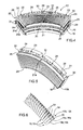
- FIG. 3 shows the walls of the teeth 15a and 16a of two polar expansions 15 and 16.
- the double axial air gap comprises a first axial air gap 23 between a face of the rotor 6, 7 and the polar expansions 15 fixed to the side wall 20, and a second axial air gap 24 between the opposite face of the rotor 6, 7 and the polar expansions 16 fixed to the other side wall 21.
- the stator windings wound around the teeth 15a and 16a For each row of polar expansions 15, 16, each stator segment 12 comprises two layers of epoxy resin 25 and 26 closing the slots between the polar expansions 15, 16 on the lower and upper parts, with the purpose of sealingly enclosing the stator windings wound around the teeth 15a and 16a.
- Figure 4 shows a single stator segment 12 without the associated rotor 6, 7 between the polar expansions 15, 16.
- the side walls 20 and 21 of the carcass 19 of each stator segment 12 have the shape, in plant, of an annulus sector whereby an annulus is formed by assembling a proper number of adjoining segments 12 ( Figure 1 ).
- the shape of the spacing member 22 is substantially that of an arc and the member is located between the two side walls 20 and 21 to maintain these latter at a mutual distance.
- Each side wall 20, 21 exhibits a plurality of through holes 28 and is arranged so that such holes 28 are coaxial to as many through holes (not shown) of the spacing member 22 to allow the passage of locking pins 11 ( Figure 1 ).
- the spacing member 22 comprise three pairs of transverse teeth 29 adapted to be coupled with corresponding pairs of notches 30 in the side walls 20 and 21 for assembling the carcass 19 and aligning the holes 28.
- the assembling of the stator segments 12 to form the double stator 3, 4 is accomplished by joining the spacing members 22 between them at their longitudinal ends by means of tightening bolts 31 to form two rings of segments 12, by stacking the two rings of segments 12 with the side walls 21 of one ring in contact with the side walls 21 of the other ring, by inserting the locking pins 11 into the holes 28 and clamping the two rings 9 and 10 around the two rings of segments 12 by means of nuts screwed to the threaded ends of the locking pins 11.
- Figure 5 shows a half of a stator segment 12, and in this particular case it shows only the wall 21 and the corresponding polar expansions 16 with the layers of epoxy resin 25 and 26 closing the corresponding slots.
- each side wall 20, 21 of the carcass 19 comprises a row of slits 32 formed on the outer surface of the wall 20, 21, uniformly distributed along the arc of the wall 20, 21 and oriented according to respective radial directions, i.e. perpendicularly to the axis 8.
- Each slit 32 radially extends for most of the height of the wall 20, 21.
- the slits 32 serve to lighten the carcass 19, but also to allow the circulation of air for cooling the air gaps 23 and 24.
- each side wall 20, 21 comprise at least an inside recess (not shown) for the circulation of a cooling fluid, capable of absorb the heat of the air circulating along the slits 32 and, therefore facilitate the cooling of the stators 3 and 4.
- each polar expansion 15, 16 formed by an intersecting plane parallel to the axis 8 has substantially an H shape and is formed by laminated material packed (stacked) along an axial direction.
- the polar expansions 15, 16 alternate with slits 33 that are substantially closed along the axial direction (i. e. parallel to the axis 8) between the heads 15b, 16b facing the axial air gaps 23, 24 and the bases 15c, 16c fixed to the corresponding side wall 20, 21 ( Figure 5 ) of the polar expansions 15, 16.
- the base 15c, 16c of each polar expansion 15, 16 comprises two comb-shaped portions 34 and 35, complementary to one another, with corresponding teeth protruding parallel to the wall 20, 21 on opposite sides of the corresponding tooth 15a, 16a. This way, by forcibly joining together the comb portions 34 with the comb portions 35 between adjacent polar expansions 15, 16, it is possible to mount the polar expansions 15, 16 along a line after the stator windings (not shown) have been wound around the teeth 15a, 16a.
- the stator windings are concentrated windings, that is they comprise, for each polar expansion 15, 16, a winding wound around the corresponding tooth 15a, 16a.
- each winding is formed by a copper sheet winding, with the sheet having a height equal to the length of the tooth 15a, 16a.
- the copper sheet winding allows a filling of the slits 33 up to 70%. An increased filling allows for building slits 33 that are shorter in the radial direction, and therefore allows to reduce the mass of the stator segments 12 while reducing at the same time the inductance of the windings, and therefore the associated voltage drop.
- the output terminals of each sheet winding are formed, for example, by copper strips of a type known as bus bars.
- each rotor 6, 7 comprise a corresponding plurality of magnetic dipoles 36, which are mounted on and uniformly distributed along the corresponding assembly circumference 6a, 7a ( Figure 3 ) of the rotatable support 5 (not shown in Figures 7 and 8 ) and laterally separated from one another in the direction of the assembly circumference 6a, 7a to prevent the magnetic field lines from being closed without completely crossing both air gaps 23 and 24.
- the side separation between the magnetic dipoles 36 allows for preventing, or at least strongly limiting, that magnetic field lines are closed through the rotor 6, 7, i.e. through adjacent magnetic dipoles 36, and the generation of non-tangential forces between the rotor 6, 7 and the stator 3, 4.
- Each magnetic dipole 36 comprises an elongated support member 37 of a ferromagnetic material ( Figure 8 ) extending along a radial direction, that is perpendicular to the axis 8, and a corresponding pair of plates 38 and 39 of permanent magnet with surfaces of opposed polarity. The plates are applied on corresponding opposed faces of the support member 37, each facing a corresponding axial air gap 23 and 24.
- Each magnetic dipole 36 is fastened to the rotatable support 5 (not shown in Figure 7 ) through a fastening member 40 integral with an end of the support member 37.
- the fastening member 40 comprises at least a shaped slot 41 for the passage of a screw to be screwed to the rotatable support 5.
- the support member 37 is made of materials known as Soft Magnetic Composites (SMC) exhibiting mechanical characteristics similar to those of the compact iron and electromagnetic characteristics similar to those of a rolled material, and this allows for reducing eddy currents.
- SMC Soft Magnetic Composites
- Such a material is for instance available with the commercial name Somaloy®,
- the transverse cross section of the support member 37 and the fastening member 40 are squared.
- the transverse cross section of the fastening member 40 is larger than that of the support member 37 so that by assembling the magnetic dipoles 36 with the fixing supports 40 adjacent to one another along the assembly circumference 6a, 7a, there is formed a certain distance or gap between adjacent supporting member 37, in other words the magnetic dipoles 36 are physically separated from one another, and therefore side air gaps are present between adjacent magnetic dipoles 36 that are capable to create a magnetic reluctance larger than the one that can be measured through the support member 37 between the two- plates 38 and 39.
- the support member 37 comprises a tooth 42 protruding from a side face of the support member 37, i.e from one of the two faces of the support member 37 transverse with respect to the faces provided with the plates 38 and 39, and a notch 43 with dimensions complementary to those of the tooth 42, this latter being formed starting from the side face opposite to that from which the tooth 42 protrudes.
- the tooth 42 of each support member 37 is adapted to be coupled with the notch 43 of an adjacent support member 37 whereby the magnetic dipoles 36 are aligned to one another along the assembly circumference 6a, 7a.
- the assembling of the magnetic dipoles 36 in the above disclosed manner defines the annulus shape of the rotor 6, 7, as shown in Figure 7 .
- each of the magnetic dipoles 36 is covered by a layer of carbon fibres (not shown) so as to realize a corresponding protective hull capable to increase the operation reliability of the electric generator 1.
- the covering is made possible by the physical separation between the magnetic dipoles 36.
- the magnetic dipoles 36 are firstly covered with the protective hull, and then they are fixed onto the rotatable support 5.
- each rotor 6, 7 comprises a plurality of elements of amagnetic material alternated with the magnetic dipoles 36 along the assembly circumference 6a, 7a to separate the magnetic dipoles 36 from one another. More particularly, each amagnetic element is arranged between two corresponding adjacent magnetic dipoles 36 and it results adjacent to the two magnetic dipoles 36 for the whole length of the corresponding support members 37.
- the generator 1 for each stator-rotor group, exhibits a relationship between the number of pairs of polar expansions 15, 16 and the number of magnetic dipoles 36 substantially comprised between 0.9 and 1.15.
- each stator segment 12 has a number of pairs of polar expansions 15, 16, equal to 36, therefore each stator 3, 4 has a number of pairs of polar expansions 15, 16 equal to 216, and each rotor 6, 7 has a number of magnetic dipoles equal to 192.
- the angle Ae is equal to 160 electric degrees, i.e. 180-20 electric degrees. Therefore, a three-phase voltage can be obtained by vectorially combining the single-phase voltages in groups of three antiseries windings, so as to cancel the 180 electric degrees phase displacement.
- the main advantage of the above disclosed electric generator 1 resides in a smaller mass in respect of known electric generators of the same power. Such mass reduction is due to a combination of characteristics.
- the structure providing for a double axial air gap allows to counterbalance the non tangential attractive forces acting between each rotor 6, 7 and the corresponding stator 3, 4.
- the formation of magnetic field lines can be strongly limited, which magnetic field lines would otherwise be closed through the rotor 6, 7, i.e. through adjacent magnetic dipoles 36, thus generating non tangential forces between each rotor 6, 7 and the corresponding stator 3, 4 also in presence of a double axial air gap structure.
- This way the double axial air gap structure and the rotor with the separate magnetic dipoles do not impose an oversizing of the supporting structure 2 to compensate non tangential forces between stator 3, 4 and rotor 6, 7.
- the deformations of such structure can be controlled with the minimum possible rigidity, since the amount of the deformations is given by the rigidity for the lever arm multiplied by the unbalancing forces.
- minimizing the required rigidity means minimizing the weight of the whole structure of the electric generator.
- the sheet copper windings allow for a greater filling of the slits 33, and therefore shorter slits can be used with all the other requirements being unchanged. This brings about a reduction of the mass of the stator segments 12.
Landscapes
- Engineering & Computer Science (AREA)
- Power Engineering (AREA)
- Life Sciences & Earth Sciences (AREA)
- Sustainable Development (AREA)
- Sustainable Energy (AREA)
- Connection Of Motors, Electrical Generators, Mechanical Devices, And The Like (AREA)
Priority Applications (1)
| Application Number | Priority Date | Filing Date | Title |
|---|---|---|---|
| EP13002449.0A EP2802062A1 (de) | 2013-05-08 | 2013-05-08 | Elektrischer Generator für einen Windkraftgenerator |
Applications Claiming Priority (1)
| Application Number | Priority Date | Filing Date | Title |
|---|---|---|---|
| EP13002449.0A EP2802062A1 (de) | 2013-05-08 | 2013-05-08 | Elektrischer Generator für einen Windkraftgenerator |
Publications (1)
| Publication Number | Publication Date |
|---|---|
| EP2802062A1 true EP2802062A1 (de) | 2014-11-12 |
Family
ID=48430414
Family Applications (1)
| Application Number | Title | Priority Date | Filing Date |
|---|---|---|---|
| EP13002449.0A Withdrawn EP2802062A1 (de) | 2013-05-08 | 2013-05-08 | Elektrischer Generator für einen Windkraftgenerator |
Country Status (1)
| Country | Link |
|---|---|
| EP (1) | EP2802062A1 (de) |
Cited By (2)
| Publication number | Priority date | Publication date | Assignee | Title |
|---|---|---|---|---|
| WO2017197497A1 (en) | 2016-04-13 | 2017-11-23 | Genesis Robotics Llp | Electric machine comprising axial thrust bearings |
| DE102022205899A1 (de) | 2022-06-10 | 2023-12-21 | Rolls-Royce Deutschland Ltd & Co Kg | Elektrische Maschine mit axialem Luftspalt für ein Luftfahrzeug |
Citations (9)
| Publication number | Priority date | Publication date | Assignee | Title |
|---|---|---|---|---|
| US6011339A (en) * | 1996-01-18 | 2000-01-04 | Shibaura Engineering Works Co., Ltd. | Motor mounted in a vehicle |
| WO2001006623A1 (en) * | 1999-04-23 | 2001-01-25 | Aerpac Holding B.V. | Generator |
| US20090072639A1 (en) * | 2007-09-19 | 2009-03-19 | Richard Lex Seneff | Segmented composite rotor |
| FR2926935A1 (fr) | 2008-01-30 | 2009-07-31 | Tecddis Sarl | Machine electrique a flux axial et a aimants permanents |
| WO2010040534A2 (de) * | 2008-10-08 | 2010-04-15 | Pro Diskus Ag | Rotor für eine elektrische maschine sowie verwendung desselben und vorrichtung und verfahren zu dessen herstellung |
| US20110042957A1 (en) | 2008-05-02 | 2011-02-24 | Hartmuth Drews | Water Wheel Comprising a Built-In Generator |
| WO2011034336A2 (ko) | 2009-09-18 | 2011-03-24 | Bang Deok Je | 직접구동식 전기기기 |
| WO2011077421A2 (en) * | 2009-12-23 | 2011-06-30 | C&F Tooling Limited | An alternator |
| US20130082545A1 (en) * | 2010-06-08 | 2013-04-04 | Kengo Goto | Linear Motor |
-
2013
- 2013-05-08 EP EP13002449.0A patent/EP2802062A1/de not_active Withdrawn
Patent Citations (10)
| Publication number | Priority date | Publication date | Assignee | Title |
|---|---|---|---|---|
| US6011339A (en) * | 1996-01-18 | 2000-01-04 | Shibaura Engineering Works Co., Ltd. | Motor mounted in a vehicle |
| WO2001006623A1 (en) * | 1999-04-23 | 2001-01-25 | Aerpac Holding B.V. | Generator |
| US20090072639A1 (en) * | 2007-09-19 | 2009-03-19 | Richard Lex Seneff | Segmented composite rotor |
| FR2926935A1 (fr) | 2008-01-30 | 2009-07-31 | Tecddis Sarl | Machine electrique a flux axial et a aimants permanents |
| US20110042957A1 (en) | 2008-05-02 | 2011-02-24 | Hartmuth Drews | Water Wheel Comprising a Built-In Generator |
| WO2010040534A2 (de) * | 2008-10-08 | 2010-04-15 | Pro Diskus Ag | Rotor für eine elektrische maschine sowie verwendung desselben und vorrichtung und verfahren zu dessen herstellung |
| WO2011034336A2 (ko) | 2009-09-18 | 2011-03-24 | Bang Deok Je | 직접구동식 전기기기 |
| US20120228965A1 (en) * | 2009-09-18 | 2012-09-13 | Bong Jun Kim | Direct-drive electric machine |
| WO2011077421A2 (en) * | 2009-12-23 | 2011-06-30 | C&F Tooling Limited | An alternator |
| US20130082545A1 (en) * | 2010-06-08 | 2013-04-04 | Kengo Goto | Linear Motor |
Cited By (7)
| Publication number | Priority date | Publication date | Assignee | Title |
|---|---|---|---|---|
| WO2017197497A1 (en) | 2016-04-13 | 2017-11-23 | Genesis Robotics Llp | Electric machine comprising axial thrust bearings |
| CN109155568A (zh) * | 2016-04-13 | 2019-01-04 | 詹尼斯机器人移动技术加拿大公司 | 包括轴向推力轴承的电机 |
| EP3443643A4 (de) * | 2016-04-13 | 2019-12-25 | Genesis Robotics and Motion Technologies Canada, ULC | Elektrische maschine mit axialdrucklagern |
| CN109155568B (zh) * | 2016-04-13 | 2021-08-03 | 詹尼斯机器人移动技术加拿大公司 | 包括轴向推力轴承的电机 |
| US11128188B2 (en) | 2016-04-13 | 2021-09-21 | Genesis Robotics And Motion Technologies Canada, Ulc | Electric machine |
| DE102022205899A1 (de) | 2022-06-10 | 2023-12-21 | Rolls-Royce Deutschland Ltd & Co Kg | Elektrische Maschine mit axialem Luftspalt für ein Luftfahrzeug |
| US12512714B2 (en) | 2022-06-10 | 2025-12-30 | Rolls-Royce Deutschland Ltd & Co Kg | Electrical machine with an axial air gap for an aircraft |
Similar Documents
| Publication | Publication Date | Title |
|---|---|---|
| TWI429168B (zh) | Permanent magnet rotating machine | |
| CN101401284B (zh) | 电机,特别是发电机 | |
| EP2869433B1 (de) | Permanentmagnetisch erregte elektrische Axialflussmaschine mit Flusskonzentration | |
| EP0627805B1 (de) | Elektromagnetische Maschine | |
| US8446121B1 (en) | High performance actuator motor | |
| CN104956573B (zh) | 电机 | |
| EP2636127B1 (de) | Segmentierter generator mit direktantrieb | |
| JP4692688B1 (ja) | 回転電機、直動電機、および風力発電システム | |
| US9722479B2 (en) | Wind turbine comprising a transverse flux electrical machine | |
| KR101239077B1 (ko) | 발전기모듈 및 이를 구비한 풍력발전장치 | |
| JP6833167B2 (ja) | 軸方向磁束回転ジェネレータ、電子回路、発電方法、電気、風力タービン、軸方向磁束回転ジェネレータの設計方法 | |
| US7982352B2 (en) | Electrical motor/generator having a number of stator pole cores being larger than a number of rotor pole shoes | |
| CN103762759B (zh) | 具有高磁隔离能力的径向磁通模块化多相电机 | |
| CN103378663B (zh) | 用于电机的机器零件的极靴结构 | |
| EP3011664B1 (de) | Elektrische maschine mit einem rotor mit schrägen permanentmagneten | |
| EP2424076B1 (de) | Segmentierte Statoranordnung | |
| GB2538516A (en) | Generator | |
| CN102545405B (zh) | 用于分段式定子组件的冷却结构 | |
| RU2581338C1 (ru) | Магнитоэлектрический генератор | |
| WO2012059109A2 (en) | Direct drive segmented generator | |
| EP2802062A1 (de) | Elektrischer Generator für einen Windkraftgenerator | |
| EP2523308B1 (de) | Blechabschnitte für ständerkern, ständerkern sowie herstellungsverfahren | |
| JP5894414B2 (ja) | 発電機 | |
| EP2713480A1 (de) | Rotor eines Permanentmagnetgenerators | |
| US20190089211A1 (en) | Electric machine comprising a stator provided with an inner tubular sleeve |
Legal Events
| Date | Code | Title | Description |
|---|---|---|---|
| PUAI | Public reference made under article 153(3) epc to a published international application that has entered the european phase |
Free format text: ORIGINAL CODE: 0009012 |
|
| 17P | Request for examination filed |
Effective date: 20130508 |
|
| AK | Designated contracting states |
Kind code of ref document: A1 Designated state(s): AL AT BE BG CH CY CZ DE DK EE ES FI FR GB GR HR HU IE IS IT LI LT LU LV MC MK MT NL NO PL PT RO RS SE SI SK SM TR |
|
| AX | Request for extension of the european patent |
Extension state: BA ME |
|
| R17P | Request for examination filed (corrected) |
Effective date: 20150512 |
|
| RBV | Designated contracting states (corrected) |
Designated state(s): AL AT BE BG CH CY CZ DE DK EE ES FI FR GB GR HR HU IE IS IT LI LT LU LV MC MK MT NL NO PL PT RO RS SE SI SK SM TR |
|
| STAA | Information on the status of an ep patent application or granted ep patent |
Free format text: STATUS: THE APPLICATION IS DEEMED TO BE WITHDRAWN |
|
| 18D | Application deemed to be withdrawn |
Effective date: 20161201 |