EP2813165B1 - Robot ménager électrique - Google Patents
Robot ménager électrique Download PDFInfo
- Publication number
- EP2813165B1 EP2813165B1 EP14177632.8A EP14177632A EP2813165B1 EP 2813165 B1 EP2813165 B1 EP 2813165B1 EP 14177632 A EP14177632 A EP 14177632A EP 2813165 B1 EP2813165 B1 EP 2813165B1
- Authority
- EP
- European Patent Office
- Prior art keywords
- vessel
- edge
- lid
- locking
- cooking vessel
- Prior art date
- Legal status (The legal status is an assumption and is not a legal conclusion. Google has not performed a legal analysis and makes no representation as to the accuracy of the status listed.)
- Active
Links
Images


Classifications
-
- A—HUMAN NECESSITIES
- A47—FURNITURE; DOMESTIC ARTICLES OR APPLIANCES; COFFEE MILLS; SPICE MILLS; SUCTION CLEANERS IN GENERAL
- A47J—KITCHEN EQUIPMENT; COFFEE MILLS; SPICE MILLS; APPARATUS FOR MAKING BEVERAGES
- A47J36/00—Parts, details or accessories of cooking-vessels
- A47J36/06—Lids or covers for cooking-vessels
- A47J36/10—Lid-locking devices
-
- A—HUMAN NECESSITIES
- A47—FURNITURE; DOMESTIC ARTICLES OR APPLIANCES; COFFEE MILLS; SPICE MILLS; SUCTION CLEANERS IN GENERAL
- A47J—KITCHEN EQUIPMENT; COFFEE MILLS; SPICE MILLS; APPARATUS FOR MAKING BEVERAGES
- A47J43/00—Implements for preparing or holding food, not provided for in other groups of this subclass
- A47J43/04—Machines for domestic use not covered elsewhere, e.g. for grinding, mixing, stirring, kneading, emulsifying, whipping or beating foodstuffs, e.g. power-driven
- A47J43/046—Machines for domestic use not covered elsewhere, e.g. for grinding, mixing, stirring, kneading, emulsifying, whipping or beating foodstuffs, e.g. power-driven with tools driven from the bottom side
-
- A—HUMAN NECESSITIES
- A47—FURNITURE; DOMESTIC ARTICLES OR APPLIANCES; COFFEE MILLS; SPICE MILLS; SUCTION CLEANERS IN GENERAL
- A47J—KITCHEN EQUIPMENT; COFFEE MILLS; SPICE MILLS; APPARATUS FOR MAKING BEVERAGES
- A47J43/00—Implements for preparing or holding food, not provided for in other groups of this subclass
- A47J43/04—Machines for domestic use not covered elsewhere, e.g. for grinding, mixing, stirring, kneading, emulsifying, whipping or beating foodstuffs, e.g. power-driven
- A47J43/07—Parts or details, e.g. mixing tools, whipping tools
- A47J43/0716—Parts or details, e.g. mixing tools, whipping tools for machines with tools driven from the lower side
-
- A—HUMAN NECESSITIES
- A47—FURNITURE; DOMESTIC ARTICLES OR APPLIANCES; COFFEE MILLS; SPICE MILLS; SUCTION CLEANERS IN GENERAL
- A47J—KITCHEN EQUIPMENT; COFFEE MILLS; SPICE MILLS; APPARATUS FOR MAKING BEVERAGES
- A47J43/00—Implements for preparing or holding food, not provided for in other groups of this subclass
- A47J43/04—Machines for domestic use not covered elsewhere, e.g. for grinding, mixing, stirring, kneading, emulsifying, whipping or beating foodstuffs, e.g. power-driven
- A47J43/07—Parts or details, e.g. mixing tools, whipping tools
- A47J43/0727—Mixing bowls
-
- A—HUMAN NECESSITIES
- A47—FURNITURE; DOMESTIC ARTICLES OR APPLIANCES; COFFEE MILLS; SPICE MILLS; SUCTION CLEANERS IN GENERAL
- A47J—KITCHEN EQUIPMENT; COFFEE MILLS; SPICE MILLS; APPARATUS FOR MAKING BEVERAGES
- A47J43/00—Implements for preparing or holding food, not provided for in other groups of this subclass
- A47J43/04—Machines for domestic use not covered elsewhere, e.g. for grinding, mixing, stirring, kneading, emulsifying, whipping or beating foodstuffs, e.g. power-driven
- A47J43/07—Parts or details, e.g. mixing tools, whipping tools
- A47J43/075—Safety devices
- A47J43/0761—Safety devices for machines with tools driven from the lower side
Definitions
- the invention relates to an electrically operated food processor according to the features of the preamble of claim 1.
- Food processors of the type in question are known. These are used, in particular, in the household sector for processing food, more preferably for preparing food. In this regard, for example, on the DE 10 2010 037892 A1 directed.
- the food processor described there has a preferably removable from a machine housing cooking vessel. This carries preferably in the bottom region of an agitator, which is drivable in particular in the assignment position of the cooking vessel in the food processor on a kitchen machine side electric motor. Further, in particular in the operation of the food processor, so preferably in the operation of the Gargefäß Disen agitator, further optionally during operation of a further preferably provided heating device for the cooking vessel, the cooking vessel is overlapped by an assignable lid.
- This cover is more preferably locked by an electric motor on the cooking vessel, so as to prevent lifting or removing the lid, especially in Rlickwerk GmbH.
- electromotively driven locking parts are provided in the aforementioned literature, which engage over the lid in the mounted on the cooking vessel position in the locked position, this further preferably at the same time engage under a vessel edge. It is known in this regard, both the cooperating with the lid edge of the vessel as well as the cooperating with the edge of the vessel area of the cover in plan to design circular, so in the circumferential direction preferably undirected placing the lid on the cooking vessel is possible.
- the invention is concerned with the task of achieving a secure locking of the lid on the cooking vessel.
- Such a torque is introduced in particular at a load from vertically below the lid edge in the locking part, including in a preferred embodiment on the elasticity of the lid, beyond optionally via a provided elastic seal a bias on the contact area or contact point between the locking member and lid outer surface is exercised ,
- a bias on the contact area or contact point between the locking member and lid outer surface is exercised .
- a certain angle of rotation alignment of the cooking vessel is predetermined relative to the locking member by formed on the cooking vessel and the locking member positive engagement means.
- the relative Rotation angle of the cooking vessel in particular to the cooking vessel of the kitchen appliance is given by the form-fitting cooperation of cooking vessel and locking part, which locking member positionally fixed, although rotatable about an axis of rotation, is arranged on the food processor.
- the one or more provided on the locking parts or the interlocking means are always offered in an insertion of the cooking vessel in the corresponding receptacle of the food processor always in the same position, so that in cooperation with the gargefäß worne positive engagement means an exact or at least approximately exact rotational angle of the cooking vessel relative to the food processor or is achieved relative to the recording.
- the interlocking means acting together still allow a relative mobility of the cooking vessel in the positive locking position by a rotation angle of 0.5 to 5 degrees, more preferably 1 to 3 degrees, more preferably, the aforementioned rotation angle range the entire area on both sides of a 0 degree ideal position includes.
- the positive locking means either on the one or more locking parts or on the cooking vessel, moreover, the positive locking means of both the or the locking parts and the cooking vessel in a preferred embodiment, only a certain rotational angle orientation of the cooking vessel relative to the locking member or to the recording of the food processor.
- the arrangement of the positive locking means provides two or more up to five rotational angle orientations of the cooking vessel relative to the locking member.
- the positive locking means of the cooking vessel are formed on the vessel edge.
- substantially radially extending webs or projections are provided, which cooperate correspondingly with the positive locking means of at least one locking part in the circumferential direction of the cooking vessel edge.
- the gargefäßrand general provided Positive locking means are preferably formed directly from the edge of the vessel, so further preferably of the same material and formed integrally therewith.
- separate means arranged in the region of the edge of the vessel can be provided, for example, projections or webs forming means attached to the edge of the vessel.
- the positive locking means at least for cooperation with the positive locking means of a locking member are spaced apart in the circumferential direction of the edge of the vessel.
- the locking part has a support region and the cooking vessel has a form-locking means adjacent to the support region.
- the support region of the locking member is used in a preferred embodiment for cooperation with the edge of the vessel, more preferably at substantially vertically downwardly open U-Querterrorismsausloom the edge of the vessel for cooperation with the resulting U-space of the vessel edge.
- the cooking vessel further preferably supports itself on the support area via the U-bar which essentially connects the vessel rim to the cooking vessel wall, wherein in a further preferred embodiment the support area is designed such that substantially also an orientation of the cooking vessel in a plane transverse to a vessel vertical axis is reached. From the aforementioned literature, the formation of such a support area on the locking part is known.
- the one or more positive locking means of the cooking vessel in particular the or in the region of the vessel edge formed interlocking means are provided in the assignment position of the cooking vessel to the locking member in the circumferential direction adjacent to the support portion of the locking member, so that at least forms a corresponding support area of the locking member, the relevant positive locking means.
- the locking part - based on a circumference of the cooking vessel - two spaced bearing areas, for the corresponding interaction with the cooking vessel, in particular with the vessel edge.
- the positive locking means of the cooking vessel are further preferably formed in the circumferential direction between the support areas, more preferably viewed in the circumferential direction in the immediate vicinity of the support areas.
- the gargefäß worne positive locking means are viewed in the circumferential direction provided on both sides outside the support areas, also here preferably further directly adjacent to these.
- the positive locking means of the cooking vessel between the bearing areas of the locking part or the bearing areas of the locking part between the positive locking means of the cooking vessel in the assignment position of the cooking vessel are preferably provided.
- the outermost edge of the cooking vessel which surrounds the support region in the vertical direction from top to bottom, to form the positive locking means of the cooking vessel, in circumferential projection on the support region of the locking member by a displacement radially inward to overlap or radially inside runs the support area. Accordingly, according to a radially offset course of the outermost edge edge of the vessel in a circumferentially limited area is preferably radially inwardly at least one positive locking means of the cooking vessel pronounced, more preferably both cooperating with a locking member positive locking means.
- a positioning over the edge of the vessel relative to the locking parts is achieved with insertion of the cooking vessel.
- two mutually parallel, provided between the edge of the vessel receiving locking members it is accordingly achieved a symmetrical positioning of the cooking vessel between the locking members and the thereto formed, preferably segmentally shaped bearing areas.
- the centering will continue here preferably achieved by a geometric embossment, for example in the form of a recess in the region of the edge of the vessel.
- the lid has a cross-section downwardly protruding edge, which overlaps the cantilevered edge of the vessel radially outward in the locking state and that the axis of rotation is radially inward to an outermost edge of the edge of the vessel and that when lying, but not in the closed position befindlichem cover meets a convex curvature of the lid edge on a deviating in cross section from a circular shape, inner peripheral edge of the locking member and by means of resilient wall and / or sealing areas from the not yet reached closure position in the closed position by the locking member can be pulled.
- a lid placed obliquely to the vessel bottom or to the vessel opening to be closed by the lid is forced into the proper vessel closure position.
- a further preferably cooperating with the Gargefäßwandung in the region of the vessel opening and arranged on the lid seal can come with placement of the lid on the edge of the vessel to an orientation of the lid, in which the cooperating with the edge of the vessel lid level in a vertical section acute angle of, for example, 1 to 10 degrees to the opening plane of the cooking vessel occupies.
- the region of the edge of the cover which points radially outwards and further preferably also towards the axially upper edge, has a curvature pointing outwards in a vertical section through the edge of the cover, which curved cover edge region in the course of the rotational displacement of at least the facing locking part with a radially inner edge
- the peripheral edge of the same cooperates.
- the rotary displacement of the locking part causes preferential sliding of the deviating from a circular inner peripheral edge of the locking member on the convex curvature of the lid edge a forced displacement of the lid portion substantially vertically downwards, preferably up to an abutment position of the lid on the peripheral edge of the vessel.
- the force required for this purpose in the locking part is received in a preferred embodiment via a cooperating with the edge of the vessel bearing point of the locking member, more preferably via a trained on the locking part support area as a reaction force.
- the radially inwardly facing contour of the locking member in the overlapping area to the lid edge is uneven, so on, in particular with respect to the Drehverlagerungsweg of the locking member.
- the inwardly facing contour is formed so that only in the locking direction of rotation of the locking member considered first portion of the contour for cooperation with the lid edge, further formed in particular with the convex shaped portion of the lid edge, while in a locking direction of rotation subsequent section of the inwardly facing contour of the locking member is formed for free, preferably spaced over-grip of the lid edge.
- the radially inward-pointing contour of the locking part is partially curved and partially rectilinear.
- the curved portion of the inwardly facing contour is at least approximately concentric with the axis of rotation of the locking member, while further preferably the rectilinear portion is directed from the curved portion substantially radially with respect to the rotational axis.
- the rectilinear portion acts accordingly in the course of the locking operation in cooperation with the lid edge in the manner of a drainage slope.
- the rectilinear section of the radially inward-pointing contour runs almost horizontally in the locking state.
- the rectilinear section runs over an at least approximately parallel section of the edge of the cover.
- An almost horizontal course here also means an orientation of the rectilinear section which encloses an acute angle of up to 5 degrees, more preferably of up to 3 degrees to a horizontal plane or to the opening plane of the vessel.
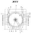
- an electrically operated food processor 1 Illustrated and described first with reference to FIG. 1 an electrically operated food processor 1.
- This first comprises a control panel 2 with preferably a plurality of controllers 3 and / or buttons and preferably a display 4 for displaying the particular parameters to be set via the controller 3 and / or buttons.
- the food processor 1 has a receptacle 5.
- a cooking vessel 6 in the form of a mixing vessel, in particular in the foot region of the same is preferably form-fitting receivable and halterbar.
- the vessel 6 is preferably formed substantially rotationally symmetrical, with a central vertical axis x.
- the vessel 6 preferably has an agitator 7. This is positively coupled in the assignment position of the vessel 6 in the receptacle 5 with a provided in the food processor 1 agitator drive.
- the vessel 6 is further closed in particular during operation of the agitator 7 and / or the heater 8 by a cover 10.
- This preferably has a central, the vertical axis x of the vessel 6 receiving, a filling opening 11, this further preferably in total substantially nikellenförmigem floor plan of the lid 10th
- the vessel 6 has a vessel wall 12 that extends upwardly from the bottom area in the vertical direction and that merges into a vessel rim 13 projecting radially outward on the vessel opening side.
- the latter is with respect to a vertical section according to Fig. 5 directed vertically downwards U-shaped, with a vertically upwardly directed, preferably parallel to the vessel bottom and thus preferably horizontally extending contact surface 14th
- the lid 10 is lower side, i. facing in allocation position substantially the contact surface 14 and the vessel interior, with a priority coaxially to the vertical axis x extending, circumferential collar 15 is provided.
- This carries a circumferential, designed to cooperate with the inner surface of the vessel wall 12 seal 18.
- the seal 18 is used in particular for fluid-tight arrangement of the lid 10 on the vessel 6 and consists in a conventional manner of a soft plastic material, for example of a thermoplastic elastomer.
- a radially outwardly extending lid edge 16 is formed. This overlaps in assignment position, the support surface 14 of the vessel edge 13 and is in the radially outer region in a substantially vertically downwardly extending edge collar 19, for embracing the radially outer U-leg of the vessel edge 13th
- the lid 10 is supported preferably on the lid edge 16, more preferably on the collar 15 on the support surface 14 of the vessel 6 from.
- the patch on the vessel 6 lid 10 is to be locked, since during operation of the food processor 1 optionally high forces, for example, by a crushing process by means of the agitator 7 and / or by a Fluid dynamics in the vessel 6 may arise.
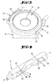
- the food processor 1 at least one locking member 17, which locks the lid 10 against the vessel 6.
- This locking member 17 is preferably elongate, wave-like, with a central, aligned in the longitudinal direction axis, which also represents a rotation axis y of the locking member 17.
- the arrangement of the rotation axis y in the illustrated embodiment is chosen so that it extends in assignment position of the cooking vessel 6 in the vessel receptacle 5 within the U-space of the vessel edge 13, further in vertical coverage by the support surface 14.
- the overall elongate cylindrical locking member 17 is arranged according to the above-described arrangement and orientation of the rotation axis y such that this with respect to a plan view (see. Fig. 2 )
- the axial length of the locking member 17 is selected so that both end portions of the same with respect to a plan view freely project beyond the secant edge, partially encompassed edge region.
- One end of the locking part 17 is connected to an electric motor 20 arranged in the food processor 1.
- the arrangement of the electric motor 20 may be selected so that its axis of rotation coincides at least in a vertical projection with the axis of rotation y of the locking member 17.
- two mutually parallel locking members 17 are provided, which are preferably rotatably driven in opposite directions in each case via an electric motor 20.
- the locking member 17 is rotatably fixed to the food processor 1 about the axis y, this the same for a total freely cantilevered arrangement.
- the overall wave-like locking member 17 is further provided with a in the illustrated embodiment, approximately over preferably 60 to 70% of the axial length of the locking member 17 extending cavity 21.
- This is designed so that in each case assigned to the viewed in the axial direction of the end portion of the cavity 21 with respect to a vertical section, ie with respect to a perpendicular to the axis of rotation y considered section, a substantially circular arc-like overreaching section 22 sets.
- This preferably extends concentrically to the axis of rotation y, wherein the covered by the overlap portion 22 cavity portion 23 is designed with respect to its radial extent as well as in terms of its extension in the circumferential direction, for substantially positive reception of the vessel edge 13 and the lid edge 16 of the patch on the vessel 6 lid 10.
- the overreaching section 22 projecting freely with respect to a vertical section in this case preferably extends like a circular arc.
- the locking regions in the region of the overlapping sections 22 which adjust as a result of the above-described embodiment are spaced apart from one another by a distance in the direction of extension of the axis of rotation y, which corresponds to approximately one third of the cover diameter in the illustrated embodiment.
- two support regions 24 are formed, in each case essentially covered, by an overlapping section 22.
- These are Favor ball-like or bale-like shape, in particular with respect to a vertical section according to Fig. 5 with a support surface, which preferably concentric with the axis of rotation y.
- the cavity 21 is formed so that in a lid release position according to Fig. 5 above the support area 24 a free vertical raising or lowering of the vessel 6 and the lid 10 can be achieved. According to the overall circular-disk-shaped configuration of the lid 10, this is non-directionally assignable to the edge of the vessel.
- the axis of rotation y of the locking part 17 preferably extends through the center of the support area 24 so as to keep the position of the vessel constant during a rotation of the locking part 17.
- the lid 10 is placed, this under direct support of the lid edge 16 on the vessel edge 13, optionally indirectly with the interposition of the seal.
- the vessel edge 13 has indentations 26 in two preferably diametrically opposite regions, more preferably in two regions which are transverse to a vessel handle 25. These are each formed by an offset radially inward of the radially outer, peripheral edge 27 of the edge of the vessel 13. This peripheral edge 27 circumferentially surrounds outside the indentations 26 formed by the bearing surfaces 14 support area in the vertical direction from top to bottom (see. Fig. 5 ).
- the indentations 26 are formed with respect to their position and their respective circumferential extent such that in the insertion position of the vessel 6 in the vessel receptacle 5, the bearing areas 24 of the locking parts 17 are received in these indentations 26, wherein each one, the indentation 26 in the circumferential direction limiting feed surface When viewed in the peripheral direction, the marginal edge 27 abuts the outside of the associated support region 24 or extends only a small distance of less than 1 mm.
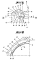
- each locking member 17 moves about the axis of rotation y and locks the lid 10 against the edge 13. If the lid 10, however, is not completely properly placed Correspondingly, for example, in an inclined position (as in Fig. 5 shown), this is pulled using the screwing locking part 17 in the closed position or urged.
- the lid edge 16 is initially provided in the transition region to the edge collar 19 outside with an outwardly facing convex curvature 30.
- the radially inward-pointing contour of the overlapping portion 22 extends non-uniformly.
- the inner contour of the locking part 17 is designed to be curved starting from essentially the end area facing the axis of rotation y, more preferably having a radius of curvature starting from the axis of rotation y approximately.
- This preferably uniformly curved contour section preferably extends over approximately two thirds of the free length of the overlapping section 22.
- the curved contour is adjoined by a contour section, which runs essentially in a straight line, preferably pointing radially inward, starting from the curved contour.
- the rectilinear contour section bears the reference numeral 31.
- the rectilinear contour section 31 of the radially inward-pointing contour of the overlap section 22 extends almost horizontally, more preferably at an acute angle of, for example, about 1 or 2 degrees radially inward (relative to the axis x) rising occupying.
- the overlapped by the rectilinear contour section 31 lid edge portion has with respect to a vertical section according to Fig. 8 a flat surface, resulting in a preferred embodiment between this surface and the facing surface of the rectilinear contour section 31, a minimal, wedge-shaped radially inner widening gap adjusts.
- each locking part 17 has two defined contact points or contact lines on the cover 10 in order to securely grasp it in all possible positions.
- the horizontal distance a corresponds in a preferred embodiment about a quarter to a half, preferably about one third of the radius between the rotation axis y and peripheral edge of the locking member 17, wherein further the contact portion 32 with respect to the vessel axis x has a greater radial dimension than the touch of the Support area 24 with the vessel edge 13th
- a bias is preferably exerted on the elasticity of the lid 10 and / or the seal 18 vertically upward in the direction of the contact region 32 between the lid edge 16 and the linearly extending contour portion 31 of the locking member 17.
- a pre-positioning in particular in the region of the locking parts 17, is provided when the vessel 6 is inserted into the vessel receptacle 5.
- the seal 18 arranged thereon comes into engagement with the inner geometry of the vessel, wherein the seal rests circumferentially in the end position and securely seals.
- a reversal of the seal 18 counteracted is also possible.
- each relative movement in particular in the circumferential direction of the cooking vessel 6 between cooking vessel 6 and lid 10, is preferably avoided.
Landscapes
- Engineering & Computer Science (AREA)
- Food Science & Technology (AREA)
- Mechanical Engineering (AREA)
- Food-Manufacturing Devices (AREA)
- Cookers (AREA)
Claims (10)
- Robot de cuisine (1) fonctionnant de manière électrique ayant un récipient de cuisson (6) et un couvercle (10) pour le récipient de cuisson (6), le couvercle (10) pouvant être verrouillé contre le récipient de cuisson (6) dans la position de fermeture, dans lequel, en outre, le récipient de cuisson (6) présente un fond de récipient de cuisson et une paroi de récipient (12) s'étendant vers le haut à partir du fond du récipient de cuisson, la paroi du récipient (12) se prolonge par un bord de récipient (13) réalisé en porte-à-faux dans la direction radiale, le couvercle (10) présente un bord de couvercle (16) qui repose en superposition avec le bord du récipient (13) dans la position de fermeture et le verrouillage est formé par une partie de verrouillage (17) destinée à saisir par le dessus le couvercle (10) qui peut être déplacée d'une position de libération à la position de verrouillage et inversement par rotation autour d'un axe (y), la partie de verrouillage (17) étant formée de façon allongée dans la direction dans laquelle l'axe (y) s'étend et, dans la position de verrouillage, saisissant le bord du récipient (13) par le dessous et le bord du couvercle (16) par le dessus, caractérisé en ce que dans l'état de verrouillage, une zone de support (24) de la partie de verrouillage (17) qui saisit le bord du récipient (13) par le dessous s'étend respectivement, au niveau de sa coopération effective avec le bord du récipient (13), par référence à une section, en décalage latéral par rapport à une zone de contact (32) de la partie de verrouillage (17) avec la surface extérieure du couvercle, le contact avec la surface extérieure du couvercle présentant une plus grande dimension radiale que le contact de la zone de support (24) avec le bord du récipient (13).
- Robot de cuisine selon la revendication 1, caractérisé en ce qu'une orientation déterminée de l'angle de rotation du récipient de cuisson (6) par rapport à la partie de verrouillage (17) est prédéfinie par des moyens d'assemblage par force mécanique (28, 29) formés sur le récipient de cuisson (6) et sur la partie de verrouillage (17).
- Robot de cuisine selon la revendication 2, caractérisé en ce que les moyens d'assemblage par force mécanique (28) du récipient de cuisson (6) sont formés sur le bord du récipient (13).
- Robot de cuisine selon la revendication 2 ou 3, caractérisé en ce qu'un moyen d'assemblage par force mécanique (28) que le récipient de cuisson (6) présente est adjacent à la zone de support (24) de la partie de verrouillage (17).
- Robot de cuisine selon l'une des revendications 1 à 4, caractérisé en ce que la partie de verrouillage (17) présente deux zones de support (24) situées à distance par référence à une circonférence du récipient de cuisson (6) et en ce que les moyens d'assemblage par force mécanique (28) du récipient de cuisson (6) sont formés entre les zones de support (24) dans la direction de la circonférence.
- Robot de cuisine selon l'une des revendications 2 à 5, caractérisé en ce qu'une arête de bord la plus à l'extérieur (27) du récipient de cuisson (6) qui saisit en l'entourant la zone de support (24) du haut vers le bas dans la direction verticale s'étend, en vue de la formation des moyens d'assemblage par force mécanique (28) du récipient de cuisson (6), dans une projection de la circonférence sur la zone de support (24) de la partie de verrouillage (17) à travers un décalage vers l'intérieur radialement en superposition ou radialement à l'intérieur par rapport à la zone de support (24).
- Robot de cuisine selon l'une des revendications précédentes, caractérisé en ce que le couvercle (10) présente une arête de bord faisant saillie vers le bas dans la section, qui dans l'état de verrouillage, saisit le bord du récipient (13) en porte-à-faux radialement vers l'extérieur par le dessus, en ce que l'axe (y) se situe radialement à l'intérieur par rapport à une arête de bord la plus à l'extérieur (27) du bord du récipient (13), en ce que lorsque le couvercle (10) est posé, mais ne se trouve pas encore dans la position de fermeture, une courbure convexe (30) du bord du couvercle (16) rencontre une arête de bord intérieure de la partie de verrouillage (17) formée en s'écartant d'une forme circulaire dans la section, et en ce que le couvercle peut être amené depuis la position de fermeture non encore atteinte jusqu'à la position de fermeture par la partie de verrouillage (17) au moyen de zones de la paroi et/ou du joint d'étanchéité flexibles élastiquement.
- Robot de cuisine selon l'une des revendications précédentes, caractérisé en ce que dans la position de fermeture, par référence à une section, un contour de la partie de verrouillage (17) se présentant vers l'intérieur radialement s'étend de façon irrégulière dans la zone de superposition jusqu'au bord du couvercle (16).
- Robot de cuisine selon la revendication 8, caractérisé en ce que le contour de la partie de verrouillage (17) se présentant vers l'intérieur radialement s'étend en partie de façon courbe et en partie de façon rectiligne.
- Robot de cuisine selon la revendication 9, caractérisé en ce que dans l'état de verrouillage, une section rectiligne (31) du contour se présentant vers l'intérieur radialement s'étend presque horizontalement.
Priority Applications (4)
| Application Number | Priority Date | Filing Date | Title |
|---|---|---|---|
| ES14177632.8T ES2553218T3 (es) | 2012-08-16 | 2012-08-16 | Máquina de cocina eléctricamente accionada |
| EP14177632.8A EP2813165B1 (fr) | 2012-08-16 | 2012-08-16 | Robot ménager électrique |
| PT141776328T PT2813165E (pt) | 2012-08-16 | 2012-08-16 | Máquina de cozinha de accionamento eléctrico |
| PL14177632T PL2813165T3 (pl) | 2012-08-16 | 2012-08-16 | Elektryczny robot kuchenny |
Applications Claiming Priority (2)
| Application Number | Priority Date | Filing Date | Title |
|---|---|---|---|
| EP14177632.8A EP2813165B1 (fr) | 2012-08-16 | 2012-08-16 | Robot ménager électrique |
| EP12180590.7A EP2698088B1 (fr) | 2012-08-16 | 2012-08-16 | Machine de cuisine électrique |
Related Parent Applications (2)
| Application Number | Title | Priority Date | Filing Date |
|---|---|---|---|
| EP12180590.7A Division EP2698088B1 (fr) | 2012-08-16 | 2012-08-16 | Machine de cuisine électrique |
| EP12180590.7A Division-Into EP2698088B1 (fr) | 2012-08-16 | 2012-08-16 | Machine de cuisine électrique |
Publications (2)
| Publication Number | Publication Date |
|---|---|
| EP2813165A1 EP2813165A1 (fr) | 2014-12-17 |
| EP2813165B1 true EP2813165B1 (fr) | 2015-09-23 |
Family
ID=46682742
Family Applications (3)
| Application Number | Title | Priority Date | Filing Date |
|---|---|---|---|
| EP14177632.8A Active EP2813165B1 (fr) | 2012-08-16 | 2012-08-16 | Robot ménager électrique |
| EP12180590.7A Active EP2698088B1 (fr) | 2012-08-16 | 2012-08-16 | Machine de cuisine électrique |
| EP14177631.0A Active EP2813164B1 (fr) | 2012-08-16 | 2012-08-16 | Robot ménager électrique |
Family Applications After (2)
| Application Number | Title | Priority Date | Filing Date |
|---|---|---|---|
| EP12180590.7A Active EP2698088B1 (fr) | 2012-08-16 | 2012-08-16 | Machine de cuisine électrique |
| EP14177631.0A Active EP2813164B1 (fr) | 2012-08-16 | 2012-08-16 | Robot ménager électrique |
Country Status (5)
| Country | Link |
|---|---|
| EP (3) | EP2813165B1 (fr) |
| CN (3) | CN107252263B (fr) |
| ES (3) | ES2553218T3 (fr) |
| PL (3) | PL2698088T3 (fr) |
| PT (3) | PT2698088E (fr) |
Cited By (3)
| Publication number | Priority date | Publication date | Assignee | Title |
|---|---|---|---|---|
| EP3875003A1 (fr) | 2020-03-06 | 2021-09-08 | Vorwerk & Co. Interholding GmbH | Récipient de préparation doté d'un dispositif de verrouillage |
| EP3875004A1 (fr) | 2020-03-06 | 2021-09-08 | Vorwerk & Co. Interholding GmbH | Récipient de préparation doté d'un dispositif de verrouillage |
| EP3875007A1 (fr) | 2020-03-06 | 2021-09-08 | Vorwerk & Co. Interholding GmbH | Récipient de préparation destiné à être raccordé à une zone de réception d'un appareil de base d'une machine de cuisine |
Families Citing this family (11)
| Publication number | Priority date | Publication date | Assignee | Title |
|---|---|---|---|---|
| DE102014112267A1 (de) | 2014-08-27 | 2016-03-03 | Vorwerk & Co. Interholding Gmbh | Küchenmaschine mit Verriegelungseinrichtung |
| DE102014112519A1 (de) | 2014-09-01 | 2016-03-03 | Vorwerk & Co. Interholding Gmbh | Abdeckelement für ein Verriegelungselement einer Küchenmaschine |
| DE102014115744A1 (de) | 2014-10-29 | 2016-05-04 | Vorwerk & Co. Interholding Gmbh | Küchenmaschine |
| DE102014119315A1 (de) * | 2014-12-22 | 2016-06-23 | Vorwerk & Co. Interholding Gmbh | Küchenmaschine, insbesondere Mixgerät |
| DE102017222457A1 (de) * | 2017-12-12 | 2019-06-13 | Vorwerk & Co. Interholding Gmbh | Speisenzubereitungsgerät mit Topfaufnahme |
| DE202018100251U1 (de) | 2018-01-17 | 2019-04-23 | Vorwerk & Co. Interholding Gmbh | Abdeckelement für ein Zubereitungsgefäß einer Küchenmaschine |
| US20210259471A1 (en) * | 2018-06-25 | 2021-08-26 | Breville Pty Limited | A blade hub assembly |
| CN113226135A (zh) * | 2018-12-21 | 2021-08-06 | 布瑞威利私人有限公司 | 搅拌器 |
| DE102019211306A1 (de) * | 2019-07-30 | 2021-02-04 | BSH Hausgeräte GmbH | Deckeleinrichtung für ein Gefäß einer Küchenmaschine, Gefäß-Deckeleinrichtungs-Kombination und Küchenmaschine |
| CN113491438B (zh) * | 2020-04-08 | 2022-06-17 | 九阳股份有限公司 | 一种电压力锅 |
| FR3111060B1 (fr) * | 2020-06-05 | 2022-04-29 | Seb Sa | Appareil de preparation culinaire |
Family Cites Families (9)
| Publication number | Priority date | Publication date | Assignee | Title |
|---|---|---|---|---|
| DE4026166A1 (de) * | 1990-08-17 | 1992-02-20 | Amc Int Alfa Metalcraft Corp | Kochgefaess |
| HUP0004662A3 (en) * | 1997-10-03 | 2001-12-28 | Seb Sa | Household electric cooking appliance, such as a food processor, comprising a simplified locking and unlocking device |
| FR2808664B1 (fr) | 2000-05-12 | 2002-07-26 | Seb Sa | Appareil electromenager de preparation culinaire comportant un dispositif de verrouillage a machoires du couvercle sur le recipient |
| DE102005028758A1 (de) * | 2005-06-22 | 2007-01-04 | Vorwerk & Co. Interholding Gmbh | Küchenmaschine mit einem Rührgefäß |
| CN2838488Y (zh) * | 2005-11-16 | 2006-11-22 | 林雅 | 一种电压力锅的内锅锁定装置 |
| EP2242405B1 (fr) * | 2008-02-08 | 2013-04-10 | Gero Vertriebs GmbH | Récipient de cuisson |
| DE102009041727A1 (de) * | 2009-09-16 | 2011-03-17 | Vorwerk & Co. Interholding Gmbh | Gefäß, insbesondere Rührgefäß für eine Küchenmaschine |
| DE102011051149B4 (de) | 2010-09-30 | 2019-09-12 | Vorwerk & Co. Interholding Gmbh | Elektrisch betriebene Küchenmaschine mit einem Gargefäß |
| DE102011050286A1 (de) * | 2011-05-11 | 2012-11-15 | Vorwerk & Co. Interholding Gmbh | Elektrisch betriebene Küchenmaschine mit einem Gargefäß |
-
2012
- 2012-08-16 EP EP14177632.8A patent/EP2813165B1/fr active Active
- 2012-08-16 PT PT121805907T patent/PT2698088E/pt unknown
- 2012-08-16 PT PT141776328T patent/PT2813165E/pt unknown
- 2012-08-16 PT PT141776310T patent/PT2813164E/pt unknown
- 2012-08-16 ES ES14177632.8T patent/ES2553218T3/es active Active
- 2012-08-16 ES ES12180590T patent/ES2530844T3/es active Active
- 2012-08-16 EP EP12180590.7A patent/EP2698088B1/fr active Active
- 2012-08-16 PL PL12180590T patent/PL2698088T3/pl unknown
- 2012-08-16 PL PL14177632T patent/PL2813165T3/pl unknown
- 2012-08-16 EP EP14177631.0A patent/EP2813164B1/fr active Active
- 2012-08-16 PL PL14177631T patent/PL2813164T3/pl unknown
- 2012-08-16 ES ES14177631.0T patent/ES2549550T3/es active Active
-
2013
- 2013-08-16 CN CN201710252192.9A patent/CN107252263B/zh active Active
- 2013-08-16 CN CN201710252130.8A patent/CN107260022B/zh active Active
- 2013-08-16 CN CN201310563641.3A patent/CN103720386B/zh active Active
Cited By (8)
| Publication number | Priority date | Publication date | Assignee | Title |
|---|---|---|---|---|
| EP3875003A1 (fr) | 2020-03-06 | 2021-09-08 | Vorwerk & Co. Interholding GmbH | Récipient de préparation doté d'un dispositif de verrouillage |
| EP3875004A1 (fr) | 2020-03-06 | 2021-09-08 | Vorwerk & Co. Interholding GmbH | Récipient de préparation doté d'un dispositif de verrouillage |
| EP3875007A1 (fr) | 2020-03-06 | 2021-09-08 | Vorwerk & Co. Interholding GmbH | Récipient de préparation destiné à être raccordé à une zone de réception d'un appareil de base d'une machine de cuisine |
| DE102021102660A1 (de) | 2020-03-06 | 2021-09-09 | Vorwerk & Co. Interholding Gesellschaft mit beschränkter Haftung | Zubereitungsgefäß mit einer Verriegelungseinrichtung |
| DE102021102660B4 (de) | 2020-03-06 | 2022-08-25 | Vorwerk & Co. Interholding Gesellschaft mit beschränkter Haftung | Zubereitungsgefäß mit einer Verriegelungseinrichtung |
| US11957275B2 (en) | 2020-03-06 | 2024-04-16 | Vorwerk &Co., Interholding GmbH | Preparation vessel for connection with a receiving area of a base unit of a food processor |
| EP4371452A2 (fr) | 2020-03-06 | 2024-05-22 | Vorwerk & Co. Interholding GmbH | Récipient de préparation destiné à être raccordé à une zone de réception d'un appareil de base d'une machine de cuisine |
| US12035849B2 (en) | 2020-03-06 | 2024-07-16 | Vorwerk & Co. Interholding Gmbh | Preparation vessel for connection with a locking assembly |
Also Published As
| Publication number | Publication date |
|---|---|
| PL2813164T3 (pl) | 2016-01-29 |
| EP2813165A1 (fr) | 2014-12-17 |
| EP2813164A1 (fr) | 2014-12-17 |
| PT2813165E (pt) | 2015-10-21 |
| EP2813164B1 (fr) | 2015-09-23 |
| ES2530844T3 (es) | 2015-03-06 |
| EP2698088B1 (fr) | 2015-01-28 |
| CN103720386B (zh) | 2017-07-14 |
| CN107252263B (zh) | 2019-09-03 |
| CN107260022A (zh) | 2017-10-20 |
| EP2698088A1 (fr) | 2014-02-19 |
| CN107260022B (zh) | 2019-10-01 |
| CN103720386A (zh) | 2014-04-16 |
| CN107252263A (zh) | 2017-10-17 |
| PT2698088E (pt) | 2015-02-10 |
| PT2813164E (pt) | 2016-01-15 |
| ES2553218T3 (es) | 2015-12-07 |
| PL2813165T3 (pl) | 2015-12-31 |
| ES2549550T3 (es) | 2015-10-29 |
| PL2698088T3 (pl) | 2015-08-31 |
Similar Documents
| Publication | Publication Date | Title |
|---|---|---|
| EP2813165B1 (fr) | Robot ménager électrique | |
| DE102011051149B4 (de) | Elektrisch betriebene Küchenmaschine mit einem Gargefäß | |
| EP2911561B1 (fr) | Robot de cuisine électrique | |
| EP2884875B1 (fr) | Robot ménager électrique | |
| EP2875762B1 (fr) | Récipient mélangeur pour un robot ménager | |
| EP3513696B1 (fr) | Robot de cuisine avec un élement de couverture pour un récipient de préparation | |
| EP2522263B1 (fr) | Machine de cuisine électrique avec récipient de cuisson | |
| EP1901640B1 (fr) | Robot menager comportant un recipient melangeur | |
| DE102009014990A1 (de) | Küchenmaschine mit einem Rührgefäß | |
| EP0292664B1 (fr) | Outil pour la préparation des aliments | |
| DE102011052745A1 (de) | Elektrisch betriebene Küchenmaschine | |
| DE102010038003B4 (de) | Deckel für ein Gargefäß sowie auf einem topfförmigen Gargefäß aufsitzender Deckel | |
| WO2015044347A1 (fr) | Dispositif pour la préparation de repas | |
| EP3468434B1 (fr) | Robot de cuisine électromotorisé | |
| EP2740392A1 (fr) | Machine de cuisine électrique | |
| DE102012103877A1 (de) | Deckel für ein Gargefäß sowie Gargefäß mit einem Deckel | |
| DE102016010675B4 (de) | Mahlbecher und Labormühle mit einem Mahlbecher | |
| DE102010016250A1 (de) | Elektromotorisch betriebene Küchenmaschine, sowie Zubereitungsgefäß | |
| DE102010037102A1 (de) | Elektromotorisch betriebene Küchenmaschine, sowie Zubereitungsgefäß | |
| DE19721302A1 (de) | Arbeitsschüssel für eine motorische Küchenmaschine |
Legal Events
| Date | Code | Title | Description |
|---|---|---|---|
| 17P | Request for examination filed |
Effective date: 20140718 |
|
| AC | Divisional application: reference to earlier application |
Ref document number: 2698088 Country of ref document: EP Kind code of ref document: P |
|
| AK | Designated contracting states |
Kind code of ref document: A1 Designated state(s): AL AT BE BG CH CY CZ DE DK EE ES FI FR GB GR HR HU IE IS IT LI LT LU LV MC MK MT NL NO PL PT RO RS SE SI SK SM TR |
|
| AX | Request for extension of the european patent |
Extension state: BA ME |
|
| PUAI | Public reference made under article 153(3) epc to a published international application that has entered the european phase |
Free format text: ORIGINAL CODE: 0009012 |
|
| R17P | Request for examination filed (corrected) |
Effective date: 20150120 |
|
| RBV | Designated contracting states (corrected) |
Designated state(s): AL AT BE BG CH CY CZ DE DK EE ES FI FR GB GR HR HU IE IS IT LI LT LU LV MC MK MT NL NO PL PT RO RS SE SI SK SM TR |
|
| GRAP | Despatch of communication of intention to grant a patent |
Free format text: ORIGINAL CODE: EPIDOSNIGR1 |
|
| RIC1 | Information provided on ipc code assigned before grant |
Ipc: A47J 36/10 20060101AFI20150211BHEP Ipc: A47J 43/046 20060101ALI20150211BHEP Ipc: A47J 43/07 20060101ALI20150211BHEP |
|
| INTG | Intention to grant announced |
Effective date: 20150306 |
|
| GRAS | Grant fee paid |
Free format text: ORIGINAL CODE: EPIDOSNIGR3 |
|
| GRAA | (expected) grant |
Free format text: ORIGINAL CODE: 0009210 |
|
| AC | Divisional application: reference to earlier application |
Ref document number: 2698088 Country of ref document: EP Kind code of ref document: P |
|
| AK | Designated contracting states |
Kind code of ref document: B1 Designated state(s): AL AT BE BG CH CY CZ DE DK EE ES FI FR GB GR HR HU IE IS IT LI LT LU LV MC MK MT NL NO PL PT RO RS SE SI SK SM TR |
|
| REG | Reference to a national code |
Ref country code: GB Ref legal event code: FG4D Free format text: NOT ENGLISH |
|
| REG | Reference to a national code |
Ref country code: CH Ref legal event code: EP |
|
| REG | Reference to a national code |
Ref country code: AT Ref legal event code: REF Ref document number: 750739 Country of ref document: AT Kind code of ref document: T Effective date: 20151015 |
|
| REG | Reference to a national code |
Ref country code: IE Ref legal event code: FG4D Free format text: LANGUAGE OF EP DOCUMENT: GERMAN Ref country code: PT Ref legal event code: SC4A Free format text: AVAILABILITY OF NATIONAL TRANSLATION Effective date: 20150928 |
|
| REG | Reference to a national code |
Ref country code: DE Ref legal event code: R096 Ref document number: 502012004711 Country of ref document: DE |
|
| REG | Reference to a national code |
Ref country code: ES Ref legal event code: FG2A Ref document number: 2553218 Country of ref document: ES Kind code of ref document: T3 Effective date: 20151207 |
|
| REG | Reference to a national code |
Ref country code: PL Ref legal event code: T3 |
|
| REG | Reference to a national code |
Ref country code: NL Ref legal event code: MP Effective date: 20150923 |
|
| PG25 | Lapsed in a contracting state [announced via postgrant information from national office to epo] |
Ref country code: FI Free format text: LAPSE BECAUSE OF FAILURE TO SUBMIT A TRANSLATION OF THE DESCRIPTION OR TO PAY THE FEE WITHIN THE PRESCRIBED TIME-LIMIT Effective date: 20150923 Ref country code: LT Free format text: LAPSE BECAUSE OF FAILURE TO SUBMIT A TRANSLATION OF THE DESCRIPTION OR TO PAY THE FEE WITHIN THE PRESCRIBED TIME-LIMIT Effective date: 20150923 Ref country code: GR Free format text: LAPSE BECAUSE OF FAILURE TO SUBMIT A TRANSLATION OF THE DESCRIPTION OR TO PAY THE FEE WITHIN THE PRESCRIBED TIME-LIMIT Effective date: 20151224 Ref country code: NO Free format text: LAPSE BECAUSE OF FAILURE TO SUBMIT A TRANSLATION OF THE DESCRIPTION OR TO PAY THE FEE WITHIN THE PRESCRIBED TIME-LIMIT Effective date: 20151223 Ref country code: LV Free format text: LAPSE BECAUSE OF FAILURE TO SUBMIT A TRANSLATION OF THE DESCRIPTION OR TO PAY THE FEE WITHIN THE PRESCRIBED TIME-LIMIT Effective date: 20150923 |
|
| REG | Reference to a national code |
Ref country code: LT Ref legal event code: MG4D |
|
| PG25 | Lapsed in a contracting state [announced via postgrant information from national office to epo] |
Ref country code: SE Free format text: LAPSE BECAUSE OF FAILURE TO SUBMIT A TRANSLATION OF THE DESCRIPTION OR TO PAY THE FEE WITHIN THE PRESCRIBED TIME-LIMIT Effective date: 20150923 Ref country code: RS Free format text: LAPSE BECAUSE OF FAILURE TO SUBMIT A TRANSLATION OF THE DESCRIPTION OR TO PAY THE FEE WITHIN THE PRESCRIBED TIME-LIMIT Effective date: 20150923 Ref country code: HR Free format text: LAPSE BECAUSE OF FAILURE TO SUBMIT A TRANSLATION OF THE DESCRIPTION OR TO PAY THE FEE WITHIN THE PRESCRIBED TIME-LIMIT Effective date: 20150923 |
|
| PG25 | Lapsed in a contracting state [announced via postgrant information from national office to epo] |
Ref country code: NL Free format text: LAPSE BECAUSE OF FAILURE TO SUBMIT A TRANSLATION OF THE DESCRIPTION OR TO PAY THE FEE WITHIN THE PRESCRIBED TIME-LIMIT Effective date: 20150923 |
|
| PG25 | Lapsed in a contracting state [announced via postgrant information from national office to epo] |
Ref country code: EE Free format text: LAPSE BECAUSE OF FAILURE TO SUBMIT A TRANSLATION OF THE DESCRIPTION OR TO PAY THE FEE WITHIN THE PRESCRIBED TIME-LIMIT Effective date: 20150923 Ref country code: IS Free format text: LAPSE BECAUSE OF FAILURE TO SUBMIT A TRANSLATION OF THE DESCRIPTION OR TO PAY THE FEE WITHIN THE PRESCRIBED TIME-LIMIT Effective date: 20160123 Ref country code: CZ Free format text: LAPSE BECAUSE OF FAILURE TO SUBMIT A TRANSLATION OF THE DESCRIPTION OR TO PAY THE FEE WITHIN THE PRESCRIBED TIME-LIMIT Effective date: 20150923 Ref country code: SK Free format text: LAPSE BECAUSE OF FAILURE TO SUBMIT A TRANSLATION OF THE DESCRIPTION OR TO PAY THE FEE WITHIN THE PRESCRIBED TIME-LIMIT Effective date: 20150923 |
|
| PG25 | Lapsed in a contracting state [announced via postgrant information from national office to epo] |
Ref country code: RO Free format text: LAPSE BECAUSE OF FAILURE TO SUBMIT A TRANSLATION OF THE DESCRIPTION OR TO PAY THE FEE WITHIN THE PRESCRIBED TIME-LIMIT Effective date: 20150923 |
|
| REG | Reference to a national code |
Ref country code: DE Ref legal event code: R097 Ref document number: 502012004711 Country of ref document: DE |
|
| PLBE | No opposition filed within time limit |
Free format text: ORIGINAL CODE: 0009261 |
|
| STAA | Information on the status of an ep patent application or granted ep patent |
Free format text: STATUS: NO OPPOSITION FILED WITHIN TIME LIMIT |
|
| REG | Reference to a national code |
Ref country code: FR Ref legal event code: PLFP Year of fee payment: 5 |
|
| 26N | No opposition filed |
Effective date: 20160624 |
|
| PG25 | Lapsed in a contracting state [announced via postgrant information from national office to epo] |
Ref country code: DK Free format text: LAPSE BECAUSE OF FAILURE TO SUBMIT A TRANSLATION OF THE DESCRIPTION OR TO PAY THE FEE WITHIN THE PRESCRIBED TIME-LIMIT Effective date: 20150923 |
|
| PG25 | Lapsed in a contracting state [announced via postgrant information from national office to epo] |
Ref country code: SI Free format text: LAPSE BECAUSE OF FAILURE TO SUBMIT A TRANSLATION OF THE DESCRIPTION OR TO PAY THE FEE WITHIN THE PRESCRIBED TIME-LIMIT Effective date: 20150923 |
|
| PG25 | Lapsed in a contracting state [announced via postgrant information from national office to epo] |
Ref country code: BE Free format text: LAPSE BECAUSE OF NON-PAYMENT OF DUE FEES Effective date: 20160831 |
|
| PG25 | Lapsed in a contracting state [announced via postgrant information from national office to epo] |
Ref country code: MC Free format text: LAPSE BECAUSE OF FAILURE TO SUBMIT A TRANSLATION OF THE DESCRIPTION OR TO PAY THE FEE WITHIN THE PRESCRIBED TIME-LIMIT Effective date: 20150923 |
|
| REG | Reference to a national code |
Ref country code: CH Ref legal event code: PL |
|
| PG25 | Lapsed in a contracting state [announced via postgrant information from national office to epo] |
Ref country code: CH Free format text: LAPSE BECAUSE OF NON-PAYMENT OF DUE FEES Effective date: 20160831 Ref country code: LI Free format text: LAPSE BECAUSE OF NON-PAYMENT OF DUE FEES Effective date: 20160831 |
|
| REG | Reference to a national code |
Ref country code: IE Ref legal event code: MM4A |
|
| PG25 | Lapsed in a contracting state [announced via postgrant information from national office to epo] |
Ref country code: IE Free format text: LAPSE BECAUSE OF NON-PAYMENT OF DUE FEES Effective date: 20160816 |
|
| REG | Reference to a national code |
Ref country code: FR Ref legal event code: PLFP Year of fee payment: 6 |
|
| PG25 | Lapsed in a contracting state [announced via postgrant information from national office to epo] |
Ref country code: LU Free format text: LAPSE BECAUSE OF NON-PAYMENT OF DUE FEES Effective date: 20160816 |
|
| PG25 | Lapsed in a contracting state [announced via postgrant information from national office to epo] |
Ref country code: HU Free format text: LAPSE BECAUSE OF FAILURE TO SUBMIT A TRANSLATION OF THE DESCRIPTION OR TO PAY THE FEE WITHIN THE PRESCRIBED TIME-LIMIT; INVALID AB INITIO Effective date: 20120816 Ref country code: SM Free format text: LAPSE BECAUSE OF FAILURE TO SUBMIT A TRANSLATION OF THE DESCRIPTION OR TO PAY THE FEE WITHIN THE PRESCRIBED TIME-LIMIT Effective date: 20150923 |
|
| PG25 | Lapsed in a contracting state [announced via postgrant information from national office to epo] |
Ref country code: MT Free format text: LAPSE BECAUSE OF FAILURE TO SUBMIT A TRANSLATION OF THE DESCRIPTION OR TO PAY THE FEE WITHIN THE PRESCRIBED TIME-LIMIT Effective date: 20150923 Ref country code: CY Free format text: LAPSE BECAUSE OF FAILURE TO SUBMIT A TRANSLATION OF THE DESCRIPTION OR TO PAY THE FEE WITHIN THE PRESCRIBED TIME-LIMIT Effective date: 20150923 Ref country code: MK Free format text: LAPSE BECAUSE OF FAILURE TO SUBMIT A TRANSLATION OF THE DESCRIPTION OR TO PAY THE FEE WITHIN THE PRESCRIBED TIME-LIMIT Effective date: 20150923 |
|
| PG25 | Lapsed in a contracting state [announced via postgrant information from national office to epo] |
Ref country code: BG Free format text: LAPSE BECAUSE OF FAILURE TO SUBMIT A TRANSLATION OF THE DESCRIPTION OR TO PAY THE FEE WITHIN THE PRESCRIBED TIME-LIMIT Effective date: 20150923 |
|
| REG | Reference to a national code |
Ref country code: FR Ref legal event code: PLFP Year of fee payment: 7 |
|
| REG | Reference to a national code |
Ref country code: AT Ref legal event code: MM01 Ref document number: 750739 Country of ref document: AT Kind code of ref document: T Effective date: 20170816 |
|
| PG25 | Lapsed in a contracting state [announced via postgrant information from national office to epo] |
Ref country code: TR Free format text: LAPSE BECAUSE OF FAILURE TO SUBMIT A TRANSLATION OF THE DESCRIPTION OR TO PAY THE FEE WITHIN THE PRESCRIBED TIME-LIMIT Effective date: 20150923 Ref country code: AL Free format text: LAPSE BECAUSE OF FAILURE TO SUBMIT A TRANSLATION OF THE DESCRIPTION OR TO PAY THE FEE WITHIN THE PRESCRIBED TIME-LIMIT Effective date: 20150923 |
|
| PG25 | Lapsed in a contracting state [announced via postgrant information from national office to epo] |
Ref country code: AT Free format text: LAPSE BECAUSE OF NON-PAYMENT OF DUE FEES Effective date: 20170816 |
|
| P01 | Opt-out of the competence of the unified patent court (upc) registered |
Effective date: 20230517 |
|
| PGFP | Annual fee paid to national office [announced via postgrant information from national office to epo] |
Ref country code: PT Payment date: 20250801 Year of fee payment: 14 Ref country code: ES Payment date: 20250917 Year of fee payment: 14 |
|
| PGFP | Annual fee paid to national office [announced via postgrant information from national office to epo] |
Ref country code: DE Payment date: 20250819 Year of fee payment: 14 |
|
| PGFP | Annual fee paid to national office [announced via postgrant information from national office to epo] |
Ref country code: PL Payment date: 20250804 Year of fee payment: 14 Ref country code: IT Payment date: 20250829 Year of fee payment: 14 |
|
| PGFP | Annual fee paid to national office [announced via postgrant information from national office to epo] |
Ref country code: GB Payment date: 20250822 Year of fee payment: 14 |
|
| PGFP | Annual fee paid to national office [announced via postgrant information from national office to epo] |
Ref country code: FR Payment date: 20250821 Year of fee payment: 14 |