EP2815190B1 - Dispositif de retenue pour un module solaire - Google Patents
Dispositif de retenue pour un module solaire Download PDFInfo
- Publication number
- EP2815190B1 EP2815190B1 EP13702206.7A EP13702206A EP2815190B1 EP 2815190 B1 EP2815190 B1 EP 2815190B1 EP 13702206 A EP13702206 A EP 13702206A EP 2815190 B1 EP2815190 B1 EP 2815190B1
- Authority
- EP
- European Patent Office
- Prior art keywords
- holder
- base plate
- support
- slot
- tongues
- Prior art date
- Legal status (The legal status is an assumption and is not a legal conclusion. Google has not performed a legal analysis and makes no representation as to the accuracy of the status listed.)
- Active
Links
Images


Classifications
-
- H—ELECTRICITY
- H10—SEMICONDUCTOR DEVICES; ELECTRIC SOLID-STATE DEVICES NOT OTHERWISE PROVIDED FOR
- H10F—INORGANIC SEMICONDUCTOR DEVICES SENSITIVE TO INFRARED RADIATION, LIGHT, ELECTROMAGNETIC RADIATION OF SHORTER WAVELENGTH OR CORPUSCULAR RADIATION
- H10F19/00—Integrated devices, or assemblies of multiple devices, comprising at least one photovoltaic cell covered by group H10F10/00, e.g. photovoltaic modules
- H10F19/80—Encapsulations or containers for integrated devices, or assemblies of multiple devices, having photovoltaic cells
-
- F—MECHANICAL ENGINEERING; LIGHTING; HEATING; WEAPONS; BLASTING
- F16—ENGINEERING ELEMENTS AND UNITS; GENERAL MEASURES FOR PRODUCING AND MAINTAINING EFFECTIVE FUNCTIONING OF MACHINES OR INSTALLATIONS; THERMAL INSULATION IN GENERAL
- F16M—FRAMES, CASINGS OR BEDS OF ENGINES, MACHINES OR APPARATUS, NOT SPECIFIC TO ENGINES, MACHINES OR APPARATUS PROVIDED FOR ELSEWHERE; STANDS; SUPPORTS
- F16M13/00—Other supports for positioning apparatus or articles; Means for steadying hand-held apparatus or articles
-
- F—MECHANICAL ENGINEERING; LIGHTING; HEATING; WEAPONS; BLASTING
- F16—ENGINEERING ELEMENTS AND UNITS; GENERAL MEASURES FOR PRODUCING AND MAINTAINING EFFECTIVE FUNCTIONING OF MACHINES OR INSTALLATIONS; THERMAL INSULATION IN GENERAL
- F16M—FRAMES, CASINGS OR BEDS OF ENGINES, MACHINES OR APPARATUS, NOT SPECIFIC TO ENGINES, MACHINES OR APPARATUS PROVIDED FOR ELSEWHERE; STANDS; SUPPORTS
- F16M7/00—Details of attaching or adjusting engine beds, frames, or supporting-legs on foundation or base; Attaching non-moving engine parts, e.g. cylinder blocks
-
- F—MECHANICAL ENGINEERING; LIGHTING; HEATING; WEAPONS; BLASTING
- F24—HEATING; RANGES; VENTILATING
- F24S—SOLAR HEAT COLLECTORS; SOLAR HEAT SYSTEMS
- F24S25/00—Arrangement of stationary mountings or supports for solar heat collector modules
- F24S25/10—Arrangement of stationary mountings or supports for solar heat collector modules extending in directions away from a supporting surface
- F24S25/13—Profile arrangements, e.g. trusses
-
- F—MECHANICAL ENGINEERING; LIGHTING; HEATING; WEAPONS; BLASTING
- F24—HEATING; RANGES; VENTILATING
- F24S—SOLAR HEAT COLLECTORS; SOLAR HEAT SYSTEMS
- F24S25/00—Arrangement of stationary mountings or supports for solar heat collector modules
- F24S25/10—Arrangement of stationary mountings or supports for solar heat collector modules extending in directions away from a supporting surface
- F24S25/16—Arrangement of interconnected standing structures; Standing structures having separate supporting portions for adjacent modules
-
- F—MECHANICAL ENGINEERING; LIGHTING; HEATING; WEAPONS; BLASTING
- F24—HEATING; RANGES; VENTILATING
- F24S—SOLAR HEAT COLLECTORS; SOLAR HEAT SYSTEMS
- F24S25/00—Arrangement of stationary mountings or supports for solar heat collector modules
- F24S25/60—Fixation means, e.g. fasteners, specially adapted for supporting solar heat collector modules
- F24S25/63—Fixation means, e.g. fasteners, specially adapted for supporting solar heat collector modules for fixing modules or their peripheral frames to supporting elements
- F24S25/632—Side connectors; Base connectors
-
- H—ELECTRICITY
- H02—GENERATION; CONVERSION OR DISTRIBUTION OF ELECTRIC POWER
- H02S—GENERATION OF ELECTRIC POWER BY CONVERSION OF INFRARED RADIATION, VISIBLE LIGHT OR ULTRAVIOLET LIGHT, e.g. USING PHOTOVOLTAIC [PV] MODULES
- H02S20/00—Supporting structures for PV modules
- H02S20/20—Supporting structures directly fixed to an immovable object
- H02S20/22—Supporting structures directly fixed to an immovable object specially adapted for buildings
- H02S20/23—Supporting structures directly fixed to an immovable object specially adapted for buildings specially adapted for roof structures
- H02S20/24—Supporting structures directly fixed to an immovable object specially adapted for buildings specially adapted for roof structures specially adapted for flat roofs
-
- H—ELECTRICITY
- H02—GENERATION; CONVERSION OR DISTRIBUTION OF ELECTRIC POWER
- H02S—GENERATION OF ELECTRIC POWER BY CONVERSION OF INFRARED RADIATION, VISIBLE LIGHT OR ULTRAVIOLET LIGHT, e.g. USING PHOTOVOLTAIC [PV] MODULES
- H02S20/00—Supporting structures for PV modules
- H02S20/30—Supporting structures being movable or adjustable, e.g. for angle adjustment
-
- F—MECHANICAL ENGINEERING; LIGHTING; HEATING; WEAPONS; BLASTING
- F24—HEATING; RANGES; VENTILATING
- F24S—SOLAR HEAT COLLECTORS; SOLAR HEAT SYSTEMS
- F24S25/00—Arrangement of stationary mountings or supports for solar heat collector modules
- F24S2025/01—Special support components; Methods of use
- F24S2025/018—Means for preventing movements, e.g. stops
-
- F—MECHANICAL ENGINEERING; LIGHTING; HEATING; WEAPONS; BLASTING
- F24—HEATING; RANGES; VENTILATING
- F24S—SOLAR HEAT COLLECTORS; SOLAR HEAT SYSTEMS
- F24S25/00—Arrangement of stationary mountings or supports for solar heat collector modules
- F24S25/60—Fixation means, e.g. fasteners, specially adapted for supporting solar heat collector modules
- F24S2025/6002—Fixation means, e.g. fasteners, specially adapted for supporting solar heat collector modules by using hooks
-
- F—MECHANICAL ENGINEERING; LIGHTING; HEATING; WEAPONS; BLASTING
- F24—HEATING; RANGES; VENTILATING
- F24S—SOLAR HEAT COLLECTORS; SOLAR HEAT SYSTEMS
- F24S30/00—Arrangements for moving or orienting solar heat collector modules
- F24S2030/10—Special components
- F24S2030/16—Hinged elements; Pin connections
-
- F—MECHANICAL ENGINEERING; LIGHTING; HEATING; WEAPONS; BLASTING
- F24—HEATING; RANGES; VENTILATING
- F24S—SOLAR HEAT COLLECTORS; SOLAR HEAT SYSTEMS
- F24S25/00—Arrangement of stationary mountings or supports for solar heat collector modules
- F24S25/60—Fixation means, e.g. fasteners, specially adapted for supporting solar heat collector modules
- F24S25/65—Fixation means, e.g. fasteners, specially adapted for supporting solar heat collector modules for coupling adjacent supporting elements, e.g. for connecting profiles together
-
- Y—GENERAL TAGGING OF NEW TECHNOLOGICAL DEVELOPMENTS; GENERAL TAGGING OF CROSS-SECTIONAL TECHNOLOGIES SPANNING OVER SEVERAL SECTIONS OF THE IPC; TECHNICAL SUBJECTS COVERED BY FORMER USPC CROSS-REFERENCE ART COLLECTIONS [XRACs] AND DIGESTS
- Y02—TECHNOLOGIES OR APPLICATIONS FOR MITIGATION OR ADAPTATION AGAINST CLIMATE CHANGE
- Y02B—CLIMATE CHANGE MITIGATION TECHNOLOGIES RELATED TO BUILDINGS, e.g. HOUSING, HOUSE APPLIANCES OR RELATED END-USER APPLICATIONS
- Y02B10/00—Integration of renewable energy sources in buildings
- Y02B10/10—Photovoltaic [PV]
-
- Y—GENERAL TAGGING OF NEW TECHNOLOGICAL DEVELOPMENTS; GENERAL TAGGING OF CROSS-SECTIONAL TECHNOLOGIES SPANNING OVER SEVERAL SECTIONS OF THE IPC; TECHNICAL SUBJECTS COVERED BY FORMER USPC CROSS-REFERENCE ART COLLECTIONS [XRACs] AND DIGESTS
- Y02—TECHNOLOGIES OR APPLICATIONS FOR MITIGATION OR ADAPTATION AGAINST CLIMATE CHANGE
- Y02B—CLIMATE CHANGE MITIGATION TECHNOLOGIES RELATED TO BUILDINGS, e.g. HOUSING, HOUSE APPLIANCES OR RELATED END-USER APPLICATIONS
- Y02B10/00—Integration of renewable energy sources in buildings
- Y02B10/20—Solar thermal
-
- Y—GENERAL TAGGING OF NEW TECHNOLOGICAL DEVELOPMENTS; GENERAL TAGGING OF CROSS-SECTIONAL TECHNOLOGIES SPANNING OVER SEVERAL SECTIONS OF THE IPC; TECHNICAL SUBJECTS COVERED BY FORMER USPC CROSS-REFERENCE ART COLLECTIONS [XRACs] AND DIGESTS
- Y02—TECHNOLOGIES OR APPLICATIONS FOR MITIGATION OR ADAPTATION AGAINST CLIMATE CHANGE
- Y02E—REDUCTION OF GREENHOUSE GAS [GHG] EMISSIONS, RELATED TO ENERGY GENERATION, TRANSMISSION OR DISTRIBUTION
- Y02E10/00—Energy generation through renewable energy sources
- Y02E10/40—Solar thermal energy, e.g. solar towers
- Y02E10/47—Mountings or tracking
-
- Y—GENERAL TAGGING OF NEW TECHNOLOGICAL DEVELOPMENTS; GENERAL TAGGING OF CROSS-SECTIONAL TECHNOLOGIES SPANNING OVER SEVERAL SECTIONS OF THE IPC; TECHNICAL SUBJECTS COVERED BY FORMER USPC CROSS-REFERENCE ART COLLECTIONS [XRACs] AND DIGESTS
- Y02—TECHNOLOGIES OR APPLICATIONS FOR MITIGATION OR ADAPTATION AGAINST CLIMATE CHANGE
- Y02E—REDUCTION OF GREENHOUSE GAS [GHG] EMISSIONS, RELATED TO ENERGY GENERATION, TRANSMISSION OR DISTRIBUTION
- Y02E10/00—Energy generation through renewable energy sources
- Y02E10/50—Photovoltaic [PV] energy
Definitions
- the invention relates to a holder for a solar module according to the preamble of claim 1.
- Such a holder is from the WO 2011/054943 A1 known.
- the known holder is adapted to the frame geometry of the solar module used in each case.
- Another holder for a solar module is from the DE 10 2010 022 556 B3 known, wherein the holder has receiving elements, each receiving element is associated with at least one attached to the base plate, variable in their distance from the receiving element support surface for supporting the side wall.
- the receiving element has a slot for insertion of the leg.
- the object of the invention is to eliminate the disadvantages of the prior art.
- a holder is to be specified which is suitable for receiving a multiplicity of different frame geometries of solar modules.
- the holder should be as simple and inexpensive to produce. Furthermore, a possible quick and easy installation of the solar module on the holder should be possible.
- a variable support surface is formed by a plurality of tongues whose distance from one end of a slot is different.
- the slot is bounded by two banks.
- the one bank of the slot is expediently inclined at an angle of 10 ° to 40 °, preferably 15 ° to 25 °, to the base plate.
- the inclination of the one bank of the slot essentially corresponds to the desired inclination of the solar module to be mounted using the holder according to the invention.
- the other bank of the slot expediently does not run parallel to one bank. It can run approximately parallel to the base plate, so that the slot opens in a V-shape. This makes it possible to introduce the leg of the frame approximately parallel to the base plate in the slot and subsequently to pivot so that it is applied to a bank substantially. In order for a side wall of the frame is simultaneously pivoted so that it passes into the region of the support surface and is supported there. Thus, the solar module is held in the pivoted state so safe and reliable in the holder.
- the fixation of the solar module. by simply plugging in and then pivoting can be performed easily and quickly. In particular, no fasteners are required
- At least one pointed projection extends from the one bank in the direction of the opposite other bank.
- several pointed projections extend in the direction of the opposite other bank.
- the proposed Pointed projections serve to pierce a possibly provided on the leg color or Eloxal Mrs or other layer, so that between the holder and the frame, an electrical contact is made. This allows a discharge of unwanted static charges from the frame via the holder to ground.
- a height of the support web corresponds to the distance of the adjacent thereto a bank of the base plate.
- the leg is not only supported by the one bank of the receiving elements, but also by the support web extending therebetween. This achieves improved load transfer from the solar module to the holder.
- the proposed holder thus allows a particularly durable recording of the frame.
- the tongues extend obliquely from the base plate in the direction of an opening plane formed by the slots.
- the tongues can be bent back into a corresponding tongue recess in the base plate. This makes it possible to first insert the frame of the solar module in the slots formed by the receiving elements, that the leg is aligned approximately parallel to the base plate. By pivoting the leg in the direction of the one bank of the slot then those tongues in the tongue recesses pushed back, which extend to below the legs of the frame.
- the longest tongue of those tongues, which is not bent back into the base plate forms the support surface for supporting the opposite side wall after the pivoting of the frame.
- a further embodiment of the invention extends from the base plate in each case opposite to the receiving element, a fixed stop.
- the fixed stop serves as a further support surface.
- the holder is thus redundant with regard to the attachment of the solar module and thus designed to be particularly secure. Even with a failure of the trained example as tongues support surface can be avoided by the proposed fixed stop a lift, for example by wind forces, the solar module from the holder.
- the holder is made of one piece of sheet metal, in particular of an aluminum or a stainless steel sheet.
- the holder can be made in particular by means of laser cutting and edges of a part.
- a support device for a solar module wherein at least one inventive holder with its base plate on a Profile rail is mounted.
- the profile rail may be, for example, a square tube.
- a support member for supporting the solar module is provided at one of the one side of the frame opposite another side at a predetermined distance from the holder.
- the support member may for example be mounted pivotably on the rail or on the frame of the solar module. Using two adjacent such support devices, it is possible to mount the solar module in the holder, to pivot and then support by means of the support member on the other side of the frame obliquely.
- the support element is expediently designed so that the solar module held in the holding element can be set up with respect to the profile rail at an angle of 10 ° to 40 °, preferably 15 ° to 25 °.
- a plurality of holders according to the invention and several, for example, pivotally supported, supporting elements are alternately mounted on a rail.
- Such supporting devices it is possible to erect several solar modules at an angle in succession.
- Such support devices are particularly suitable for Aufêtrn of solar modules on flat roofs.
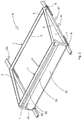
- a rectangular frame R of a solar module (not shown here) is shown here.
- the frame R has two opposing first struts 1 and two opposing second struts 2.
- the struts 2 are formed shorter than the first struts 1.
- the struts 1, 2 are each formed in the manner of a U-profile, wherein a free leg 3 faces to a frame R enclosed by the frame inside out.
- a circumferential side wall of the frame R is designated by the reference numeral 4.
- the reference symbols S1 and S2 designate supporting devices.
- Each of the support devices S1, S2 has a profile rail 5, which is formed for example from a square tube.
- a holder 6 is mounted on an upper side O of the rail 5.
- a support 7 is pivotally mounted on the rail 5.
- elastomeric elements are referred to, which are attached to a bottom U of the rail 5 and fixed, for example by means of an adhesive.
- the support 7 is formed in the manner of a U-profile. It has a profile base section 9 and two legs 10 extending opposite to each other. From the thighs 10 extend each pivot mounting portions 11 having a first opening 12 are guided by the fastening means (not shown here), so that the support 7 is pivotally supported on the rail 5.
- a first width B1 of the profile base section 9 in the vicinity of the pivot attachment sections 11 is smaller than a second width B2 in the vicinity of a free end of the support 7.
- the profile base section 9 thus has a trapezoidal shape.
- a fastening element 13 provided at the free end of the support 7 comprises fastening sections 14 which extend from the legs 10.
- Each of the attachment portions 14 has a slot 15 which opens to the profile base section 9.
- a securing portion 16 is also provided, which is formed by a bent by about 90 ° from the profile base portion 9 tab.
- the securing section 16 has a second opening 17.
- the reference numeral 18 denotes third openings, which are provided in the profile base section 9.
- holder 6 has a base plate 19, from which receiving elements 20 each having a further slot 21 extend.
- the holder 6 is mounted with respect to the support 7 on the top O of the rail 5, that the further slot 21 opens with respect to the slot 15 in an opposite direction.
- a fixed stop 22 is provided in each case.
- the one bank U1 of the further slot 21 forms here with the base plate 19 approximately at an angle of 20 °. From the one shore U1 extend in the direction of the opposite other bank U2 pointed projections 23. The pointed projections 23 are suitably hardened. Curing can be accomplished by making the pointed projections 23 by laser cutting and then rapidly cooling them. Between the receiving elements 20 a of the base plate 19 extending support web 24 is provided. A designated by the reference numeral H1 height of the support bar 24 corresponds to the distance A1 of the adjacent thereto a bank U1 of the base plate 19th
- Tongues 25a, 25b, 25c and 25d extend obliquely from the base plate 19 in the direction of an opening plane formed by the further slots 21 or the legs 3 inserted therein.
- the tongues 25a-25d differ in their length and thus in their distance from one end E of the further slot 21.
- the leg 3 may have different depths according to the lines L1, L2, L3, L4.
- the side wall 4 extends from the leg 3 in the region of the line L1.
- the side wall 4 (not shown here) would be supported by the support surface Sf formed by the tongue 25c.
- a side wall 4 extending therefrom would be supported by the support surface Sf formed by the tongue 25b.
- a leg 3 with the depth L4 serves as a support surface of the fixed stop 22nd
- the leg 3 of the frame R For mounting of the solar module in the holder 6, first, the leg 3 of the frame R in approximately parallel orientation to the base plate 19 in the other slot 21 to the concern whose end E is inserted. Then, the leg 3 is pivoted so that it comes to rest on about one bank U1. In this case, the pointed projections 23 penetrate a provided on the leg 3 anodized or colored layer. At the same time, depending on the depth L1-L4 of the leg 3, the tongues 25a-25d located under the leg 3 are bent back in the direction of the base plate 19. The longest of those tongues 25a-25d, which are not under this when pivoting the leg 3, remain in their obliquely upwardly bent position and thus form a support surface Sf for supporting the side wall 4 extending from the leg 3 (not shown here).
- Fig. 4 shows a plan view of another support 26.
- the further support 26 has a further securing portion 27.
- the further securing portion 27 in turn is substantially symmetrical and has a first tongue 28 which is provided with the second opening 17.
- first tongues 28 extend with a wide first depth in the direction of the fastening portion 14
- the second tongues 29 extend with a further second depth L2 in the direction of the fastening portion 14
- the third tongues 30 extend with a third depth L3 in the direction of the fastening portion 14.
- the first depth L1 is smaller than the second depth L2; the second depth L2 is smaller than the third depth L3.
- the further securing portion 27 it is possible to fasten 26 differently configured frame geometries by means of the further support.
- a frame R can be secured in the second opening 17, the leg 3 of which extends, for example, over the third tongues 30.
- such a frame R can be secured by bending up the first 28 and the second tongues 29.
- the proposed further support 26 is thus suitable universally for attachment of a variety of solar modules on the market.
- the holder 6 and the support 7 are advantageously formed from sheets produced by means of laser cutting, which are subsequently folded. Both the holder 6 and the support 7 are suitably made in one piece.
- the holder 6 and the support 7 each serve to support two adjacent solar modules.
- a plurality of holders 6 and supports 7 may be mounted alternately on a rail 5.
- a support device S1, S2 can be used in this case for supporting a plurality of solar modules in succession, which further improves the efficiency of the device.
Landscapes
- Engineering & Computer Science (AREA)
- General Engineering & Computer Science (AREA)
- Mechanical Engineering (AREA)
- Sustainable Energy (AREA)
- Physics & Mathematics (AREA)
- Life Sciences & Earth Sciences (AREA)
- Sustainable Development (AREA)
- Thermal Sciences (AREA)
- Chemical & Material Sciences (AREA)
- Combustion & Propulsion (AREA)
- Civil Engineering (AREA)
- Structural Engineering (AREA)
- Architecture (AREA)
- Photovoltaic Devices (AREA)
- Roof Covering Using Slabs Or Stiff Sheets (AREA)
Claims (12)
- Dispositif de retenue (6) pour un module solaire pourvu d'un cadre rectangulaire (R) qui comporte une paroi latérale périphérique (4) à partir de laquelle s'étend sur au moins une face un côté (3) orienté vers l'intérieur du cadre, en ce que le dispositif de retenue (6) comporte une plaque de base (19) à partir de laquelle s'étendent deux éléments récepteurs (20) destinés à recevoir le côté (3), en ce que chaque élément récepteur (20) est associé à au moins une surface d'appui (Sf) destinée à supporter la paroi latérale (4), située sur la plaque de base (19) et dont l'écart par rapport à l'élément récepteur (20) peut être modifié,
en ce que les éléments récepteurs (20) comportent respectivement une rainure (21) destinée à insérer le côté (3),
caractérisé en ce que
la surface d'appui (Sf) variable est formée par une pluralité de languettes (25a-25d) dont l'écart par rapport à une extrémité (E) de la rainure (21) est différent. - Dispositif de retenue (6) selon la revendication 1, en ce que l'un des bords (U1) de la rainure (21) est incliné vers la plaque de base (19) à un angle de 10 à 40°, de préférence de 15 à 25°.
- Dispositif de retenue (6) selon l'une des revendications précédentes, en ce qu'au moins une saillie pointue (23) s'étend à partir d'un bord (U1) de la rainure (21) vers l'autre bord (U2) opposé.
- Dispositif de retenue (6) selon l'une des revendications précédentes, en ce qu'une traverse support (24) s'étendant à partir de la plaque de base (19) est prévue entre les éléments récepteurs (20).
- Dispositif de retenue (6) selon la revendication 4, en ce qu'une hauteur (H1) de la traverse support (24) correspond à l'écart (A1) de l'un des bords (U1) de la rainure (21) de la plaque de base (19) qui y est adjacent.
- Dispositif de retenue (6) selon l'une des revendications précédentes, en ce que les languettes (25a-25d) s'étendent de manière inclinée à partir de la plaque de base (19) vers un plan d'ouverture formée par les rainures (21).
- Dispositif de retenue (6) selon l'une des revendications précédentes, en ce que les languettes (25a-25d) peuvent être recourbées dans un évidement de languette correspondant dans la plaque de base (19).
- Dispositif de retenue (6) selon l'une des revendications précédentes, en ce qu'une butée fixe (22) respectivement opposée aux éléments récepteurs (20) s'étend à partir de la plaque de base (19).
- Dispositif de retenue (6) selon l'une des revendications précédentes, en ce que le dispositif de retenue (6) est en une pièce, réalisé en tôle, en particulier en une tôle d'aluminium ou d'acier inoxydable.
- Dispositif de support (S1, S2) pour un module solaire, en ce qu'au moins un dispositif de retenue (6) selon l'une des revendications précédentes est monté avec sa plaque de base (19) sur un rail profilé (5).
- Dispositif de support (S1, S2) selon la revendication 10, en ce que, à un écart prédéfini du dispositif de retenue (6), un élément de support (7) est prévu pour le support du module solaire sur une autre face opposée à l'une des faces du cadre (R).
- Dispositif de support (S1, S2) selon la revendication 10 ou 11, en ce que l'élément de support (7) est réalisé de manière à ce que le rail profilé (5) du module solaire retenu dans le dispositif de retenue (6) puisse être installé à un angle de 10 à 40°, de préférence de 15 à 25°.
Applications Claiming Priority (4)
| Application Number | Priority Date | Filing Date | Title |
|---|---|---|---|
| DE202012001369 | 2012-02-13 | ||
| DE202012004333U DE202012004333U1 (de) | 2012-02-13 | 2012-05-03 | Vorrichtung zum Abstützen zumindest eines Solarmoduls |
| DE102012208480.0A DE102012208480C5 (de) | 2012-02-13 | 2012-05-21 | Halter für ein Solarmodul sowie Stützvorrichtung |
| PCT/EP2013/051373 WO2013120677A1 (fr) | 2012-02-13 | 2013-01-24 | Dispositif de retenue pour un module solaire |
Publications (2)
| Publication Number | Publication Date |
|---|---|
| EP2815190A1 EP2815190A1 (fr) | 2014-12-24 |
| EP2815190B1 true EP2815190B1 (fr) | 2016-04-27 |
Family
ID=47828259
Family Applications (2)
| Application Number | Title | Priority Date | Filing Date |
|---|---|---|---|
| EP13702206.7A Active EP2815190B1 (fr) | 2012-02-13 | 2013-01-24 | Dispositif de retenue pour un module solaire |
| EP13702207.5A Active EP2815191B1 (fr) | 2012-02-13 | 2013-01-24 | Dispositif de support pour au moins un module solaire |
Family Applications After (1)
| Application Number | Title | Priority Date | Filing Date |
|---|---|---|---|
| EP13702207.5A Active EP2815191B1 (fr) | 2012-02-13 | 2013-01-24 | Dispositif de support pour au moins un module solaire |
Country Status (8)
| Country | Link |
|---|---|
| US (2) | US9312414B2 (fr) |
| EP (2) | EP2815190B1 (fr) |
| AU (2) | AU2013220617B2 (fr) |
| CA (2) | CA2863671C (fr) |
| DE (3) | DE202012004333U1 (fr) |
| HU (2) | HUE027843T2 (fr) |
| PL (2) | PL2815191T3 (fr) |
| WO (2) | WO2013120677A1 (fr) |
Cited By (1)
| Publication number | Priority date | Publication date | Assignee | Title |
|---|---|---|---|---|
| CN105991086A (zh) * | 2015-02-13 | 2016-10-05 | 株式会社森瑞尔 | 太阳能电池板架台 |
Families Citing this family (23)
| Publication number | Priority date | Publication date | Assignee | Title |
|---|---|---|---|---|
| EP2304337A1 (fr) * | 2008-05-08 | 2011-04-06 | Solar Power, Inc. | Système de supports pour panneaux solaires montés sur toiture en terrasse |
| US20150377521A1 (en) * | 2011-03-01 | 2015-12-31 | Jonathan Port | Strap mount for solar panels |
| EP2746695A1 (fr) * | 2012-12-19 | 2014-06-25 | SST Holding GmbH | Système photovoltaïque |
| US9705447B2 (en) | 2013-03-28 | 2017-07-11 | Georgia Tech Research Corporation | Mounting clips for panel installation |
| DE202013003496U1 (de) * | 2013-03-28 | 2013-06-03 | Werner Ilzhöfer | Befestigungselement zum Befestigen von Solarmodulen an einer geneigten Dachfläche |
| WO2015042260A1 (fr) * | 2013-09-18 | 2015-03-26 | Zep Solar Llc | Réseau photovoltaïque monté à pente faible |
| CA2830914C (fr) * | 2013-10-11 | 2018-06-26 | Polar Racking Inc. | Support pour panneau solaire |
| EP3097369A1 (fr) * | 2014-01-24 | 2016-11-30 | Renusol GmbH | Unité pied d'appui servant à stabiliser des panneaux solaires sur un toit plat |
| DE102014105384B4 (de) * | 2014-04-15 | 2016-01-14 | Jürgen Rupp | Montagesystem für ein durch plattenförmige Elemente abgedecktes Flächenheiz- oder Kühlsystem |
| DE102014208303B4 (de) * | 2014-05-02 | 2022-09-01 | Werner Ilzhöfer | Befestigungsvorrichtung zur Befestigung von Photovoltaikmodulen |
| US12410015B2 (en) | 2015-01-23 | 2025-09-09 | Fluke Corporation | Solar module carriers and related systems |
| US11286114B2 (en) * | 2015-01-23 | 2022-03-29 | Vivint Solar, Inc. | Solar module carrier |
| US10036577B2 (en) * | 2015-08-07 | 2018-07-31 | David Ching | Photovoltaic module mounting and installation system |
| US9874006B1 (en) | 2016-08-01 | 2018-01-23 | Inhabit Solar, Llc | Modular roof mounting system |
| US9628019B1 (en) * | 2016-09-09 | 2017-04-18 | Polar Racking Inc. | Photovoltaic panel racking system |
| CN108645048B (zh) * | 2018-04-28 | 2020-09-22 | 济宁市兖州区龙升新能源科技有限公司 | 新型壁挂式太阳能集热板及加工方法和安装方法 |
| DE102018209482B3 (de) | 2018-06-13 | 2019-10-17 | K2 Systems Gmbh | Lagereinrichtung, Solaranlagenanordnung |
| AU2019356905B2 (en) | 2018-10-08 | 2025-04-10 | The Board Of Regents Of The University Of Oklahoma | System for mounting solar panels |
| US11444570B2 (en) | 2020-02-28 | 2022-09-13 | OffGrid Power Solutions, LLC | Modular solar skid with enclosures |
| WO2022020626A1 (fr) | 2020-07-23 | 2022-01-27 | The Board Of Regents Of The University Of Oklahoma | Adaptateur pour élément de fixation de module photovoltaïque à base de ressorts |
| EP4382825A1 (fr) * | 2022-12-06 | 2024-06-12 | voestalpine Metal Forming GmbH | Élément de support métallique pour au moins un élément solaire et installation solaire comprenant ledit élément de support. |
| USD1113652S1 (en) * | 2023-11-28 | 2026-02-17 | Guangzhou Issyzone Technology Co., Limited | Solar panel mounting bracket |
| USD1072796S1 (en) * | 2024-10-12 | 2025-04-29 | Hangzhou Sici Fangcheng Design Co., Ltd | TV stand |
Family Cites Families (39)
| Publication number | Priority date | Publication date | Assignee | Title |
|---|---|---|---|---|
| DE19934073B4 (de) * | 1999-07-19 | 2005-08-25 | Regen Energiesysteme Gmbh | Vorrichtung zur Befestigung von Solarmodulen |
| NL1017567C2 (nl) * | 2001-03-12 | 2002-09-20 | Jazo Zevenaar B V | Houder voor een fotovolta´sch paneel. |
| JP2003035016A (ja) | 2001-07-26 | 2003-02-07 | Ykk Ap Inc | 形材の固定構造およびこれを用いた太陽光発電用設置架台 |
| WO2007079382A2 (fr) * | 2005-12-28 | 2007-07-12 | Sunpower Corporation, Systems | Ensemble module photovoltaïque (pv) supporté |
| JP2008214875A (ja) * | 2007-02-28 | 2008-09-18 | Sharp Corp | 太陽電池モジュールの取付け構造 |
| DE202007006094U1 (de) * | 2007-04-27 | 2008-09-04 | Meier, Christian | Solarmodul-Anordnung mit Tragvorrichtung |
| DE202007008150U1 (de) * | 2007-06-11 | 2007-12-13 | Meier, Christian | Befestigungsvorrichtung für Solarmodule |
| DE202007008471U1 (de) | 2007-06-13 | 2007-09-27 | Leichtmetallbau Schletter Gmbh | Vorrichtung zum Verbinden einer Profilschiene mit einem anderen Bauteil |
| FR2918397A1 (fr) * | 2007-07-06 | 2009-01-09 | Terreal Soc Par Actions Simpli | Dispositif d'integration de panneau solaire sur un toit, en particulier pour du solaire photovoltaique. |
| JP4202401B1 (ja) * | 2007-08-09 | 2008-12-24 | シャープ株式会社 | 構造物設置架台、その組立方法、太陽電池モジュール、及び構造物設置架台を用いた施工構造 |
| US8505248B1 (en) * | 2007-09-21 | 2013-08-13 | Andalay Solar, Inc. | Minimal ballasted surface mounting system and method |
| NL2001092C2 (nl) * | 2007-12-14 | 2009-06-16 | Renusol Gmbh | Drager voor een zonnepaneel. |
| AT506323B1 (de) * | 2008-01-21 | 2009-08-15 | Vaillant Austria Gmbh | Vorrichtung zur befestigung eines solarkollektors |
| DE202008000997U1 (de) * | 2008-01-23 | 2008-05-15 | Solarpower Gmbh | Befestigungssystem |
| DE202008009241U1 (de) * | 2008-07-10 | 2009-11-26 | Rehau Ag + Co | Halteprofil und Dichtprofil für plattenförmige Module |
| DE102008052662A1 (de) * | 2008-10-22 | 2010-05-27 | Michelberger Energietechnik Gmbh | Montagesystem |
| DE202009003124U1 (de) | 2009-03-09 | 2009-05-20 | C&L Gmbh | Halterung für Unterkonstruktion von Solarmodulen sowie Unterkonstruktion von Solarmodulen |
| DE102009022746A1 (de) * | 2009-05-26 | 2011-05-19 | Kieselbach Solar Gmbh | Befestigungsvorrichtung für Solaranlagen |
| DE202009007481U1 (de) * | 2009-05-26 | 2010-10-07 | Rwenergy Gmbh | Solarträgerkonsole |
| DE202009007526U1 (de) * | 2009-05-27 | 2009-08-20 | Schletter Gmbh | Vorrichtung zur Befestigung einer Montageschiene an einem Gewindeschaft |
| DE112010004299A5 (de) | 2009-11-06 | 2012-09-27 | Werner Ilzhöfer | Solarmodul mit schwenkbarer stützwand |
| DE202009016197U1 (de) * | 2009-11-30 | 2010-03-25 | Vm Edelstahltechnik Gmbh | Zur Befestigung eines Gegenstandes dienendes Halteelement und Befestigungseinrichtung für Solarmodule |
| DE102010022556B3 (de) * | 2010-06-02 | 2011-06-30 | A. Raymond Et Cie S.C.S. | Vorrichtung zum Befestigen eines Solarmoduls |
| DE202010005563U1 (de) * | 2010-06-04 | 2010-09-02 | SCHÜCO International KG | Montagevorrichtung für Solarkollektoren |
| DE102010024514B4 (de) * | 2010-06-21 | 2011-12-29 | Jürgen Ulrich | Rahmen für ein Solarmodul sowie Montageverfahren für einen derartigen Rahmen |
| DE102010017705A1 (de) * | 2010-07-02 | 2012-01-05 | Patrik Diwald | Montagevorrichtung zur Anordnung von Solarmodulen |
| WO2012014203A2 (fr) * | 2010-07-26 | 2012-02-02 | Efraim Molek | Mécanisme de verrouillage pour panneaux |
| US8522491B2 (en) * | 2010-08-12 | 2013-09-03 | Centrosolar AG | Support device for mounting a solar panel and mounting system incorporating same |
| DE102010060154A1 (de) * | 2010-10-25 | 2012-04-26 | Michael Huhn | Modulblock zur Aufnahme eines Photovoltaikmoduls |
| US20120186632A1 (en) * | 2011-01-25 | 2012-07-26 | Computer Components Corporation | Mounting Assembly for Supporting a Solar Panel, and Method of Employing Same |
| US20120186169A1 (en) * | 2011-01-25 | 2012-07-26 | Paul Anthony Tomaso | Roof mount ballast solar racking system |
| US8726897B2 (en) * | 2011-03-15 | 2014-05-20 | Sunedison, Llc | Collapsible solar module support system and method for assembling the same |
| DE102011017518A1 (de) * | 2011-04-26 | 2012-10-31 | Hilti Aktiengesellschaft | Solaranordnung |
| US10302333B2 (en) * | 2011-09-30 | 2019-05-28 | Sunrun South Llc | Wind tunnel optimized solar panel system |
| US9038329B2 (en) * | 2011-10-11 | 2015-05-26 | Sunlink Corporation | Structure following roof mounted photovoltaic system |
| FR2983570B1 (fr) * | 2011-12-06 | 2018-07-06 | Terreal | Platine de fixation pour couloir lateral de systeme de panneaux photovoltaiques en couverture |
| DE202011108873U1 (de) * | 2011-12-09 | 2012-01-19 | Green Factory Gmbh | Vorrichtung zum Befestigen eines Moduls zur Nutzung von Sonnenenergie |
| DE202012002547U1 (de) * | 2012-03-14 | 2012-04-17 | Werner Ilzhöfer | Vorrichtung zum Abstützen von Solarmodulen |
| CN103258885B (zh) * | 2013-06-05 | 2015-12-23 | 友达光电股份有限公司 | 用以支撑太阳能模块的支架 |
-
2012
- 2012-05-03 DE DE202012004333U patent/DE202012004333U1/de not_active Expired - Lifetime
- 2012-05-21 DE DE102012208480.0A patent/DE102012208480C5/de active Active
- 2012-05-21 DE DE202012012485U patent/DE202012012485U1/de not_active Expired - Lifetime
-
2013
- 2013-01-24 CA CA2863671A patent/CA2863671C/fr active Active
- 2013-01-24 US US14/377,415 patent/US9312414B2/en active Active
- 2013-01-24 PL PL13702207.5T patent/PL2815191T3/pl unknown
- 2013-01-24 EP EP13702206.7A patent/EP2815190B1/fr active Active
- 2013-01-24 AU AU2013220617A patent/AU2013220617B2/en not_active Ceased
- 2013-01-24 WO PCT/EP2013/051373 patent/WO2013120677A1/fr not_active Ceased
- 2013-01-24 CA CA2864477A patent/CA2864477C/fr active Active
- 2013-01-24 HU HUE13702207A patent/HUE027843T2/en unknown
- 2013-01-24 AU AU2013220618A patent/AU2013220618A1/en not_active Abandoned
- 2013-01-24 EP EP13702207.5A patent/EP2815191B1/fr active Active
- 2013-01-24 WO PCT/EP2013/051375 patent/WO2013120678A1/fr not_active Ceased
- 2013-01-24 PL PL13702206.7T patent/PL2815190T3/pl unknown
- 2013-01-24 US US14/377,399 patent/US9406827B2/en active Active
- 2013-01-24 HU HUE13702206A patent/HUE027844T2/en unknown
Cited By (1)
| Publication number | Priority date | Publication date | Assignee | Title |
|---|---|---|---|---|
| CN105991086A (zh) * | 2015-02-13 | 2016-10-05 | 株式会社森瑞尔 | 太阳能电池板架台 |
Also Published As
| Publication number | Publication date |
|---|---|
| HUE027843T2 (en) | 2016-11-28 |
| US20140360951A1 (en) | 2014-12-11 |
| US9406827B2 (en) | 2016-08-02 |
| WO2013120678A1 (fr) | 2013-08-22 |
| CA2864477C (fr) | 2020-12-29 |
| CA2864477A1 (fr) | 2013-08-22 |
| CA2863671C (fr) | 2020-12-29 |
| EP2815190A1 (fr) | 2014-12-24 |
| US20150340987A1 (en) | 2015-11-26 |
| US9312414B2 (en) | 2016-04-12 |
| AU2013220617A1 (en) | 2014-09-04 |
| DE202012012485U1 (de) | 2013-03-21 |
| PL2815191T3 (pl) | 2016-10-31 |
| DE202012004333U1 (de) | 2013-02-01 |
| AU2013220618A1 (en) | 2014-09-04 |
| AU2013220617B2 (en) | 2017-07-13 |
| HUE027844T2 (en) | 2016-11-28 |
| PL2815190T3 (pl) | 2016-10-31 |
| EP2815191A1 (fr) | 2014-12-24 |
| EP2815191B1 (fr) | 2016-04-27 |
| WO2013120677A1 (fr) | 2013-08-22 |
| DE102012208480B3 (de) | 2013-05-08 |
| DE102012208480C5 (de) | 2017-05-04 |
| CA2863671A1 (fr) | 2013-08-22 |
Similar Documents
| Publication | Publication Date | Title |
|---|---|---|
| EP2815190B1 (fr) | Dispositif de retenue pour un module solaire | |
| EP1725068A2 (fr) | Fixation par encliquetage pour ensemble d'enceintes de haut-parleur | |
| DE102018114621A1 (de) | Trägersystem zur Anordnung einer Photovoltaikeinheit aufweisend mindestens ein Photovoltaikmodul | |
| DE202008011312U1 (de) | Verriegelungssystem zum Verriegeln von flächigen Solarmodulen | |
| EP4435201A2 (fr) | Système de façade et élément de retenue destiné à fixer des profilés visibles | |
| DE202007006094U1 (de) | Solarmodul-Anordnung mit Tragvorrichtung | |
| DE202011050810U1 (de) | Stützelement für eine Unterkonstruktion für ein Solarmodul | |
| EP2389836B1 (fr) | Rayonnage | |
| DE202010012937U1 (de) | Befestigungssystem | |
| DE102010004652A1 (de) | Indach-Solarkollektormontageanordnung | |
| DE102014208303B4 (de) | Befestigungsvorrichtung zur Befestigung von Photovoltaikmodulen | |
| EP1965625B1 (fr) | Support variable | |
| AT513687B1 (de) | Vorrichtung zur Abwehr von Vögeln, vorzugsweise von Tauben | |
| DE202010002489U1 (de) | Indach-Solarkollektormontageanordnung | |
| DE102012004773A1 (de) | Vorrichtung für die Halterung von Photovoltaikmodulen auf Freiflächen | |
| DE202010004995U1 (de) | Befestiger zur Befestigung eines ersten Bauteils an einem zweiten Bauteil | |
| DE202011002872U1 (de) | Verkaufsregal | |
| DE202012009700U1 (de) | Dachhaken | |
| DE102012102243A1 (de) | Rahmenbausatz, Solarmodulvorrichtung und Solarmodul-Montageverfahren | |
| DE202021104687U1 (de) | Schneefangstütze und Schneebremssystem | |
| DE202012102167U1 (de) | Montagevorrichtung | |
| EP2309070B1 (fr) | Elément de construction pour plaques de plafond et d'arc formeret ainsi que procédé de fabrication de celui-ci | |
| DE102023113168A1 (de) | Verbinder für eine schraublose Verbindung einer Gittermatte an einen Zaunpfosten | |
| DE202023105538U1 (de) | Befestigungsvorrichtung zur Befestigung von wenigstens einem Bauteil, insbesondere wenigstens einem Tragelement von Photovoltaik- und/oder Solarthermiemodulen, an einem geneigten Dach, sowie Verwendung einer solchen Befestigungsvorrichtung | |
| EP4459202A1 (fr) | Systeme de lestage |
Legal Events
| Date | Code | Title | Description |
|---|---|---|---|
| PUAI | Public reference made under article 153(3) epc to a published international application that has entered the european phase |
Free format text: ORIGINAL CODE: 0009012 |
|
| 17P | Request for examination filed |
Effective date: 20140911 |
|
| AK | Designated contracting states |
Kind code of ref document: A1 Designated state(s): AL AT BE BG CH CY CZ DE DK EE ES FI FR GB GR HR HU IE IS IT LI LT LU LV MC MK MT NL NO PL PT RO RS SE SI SK SM TR |
|
| AX | Request for extension of the european patent |
Extension state: BA ME |
|
| DAX | Request for extension of the european patent (deleted) | ||
| GRAP | Despatch of communication of intention to grant a patent |
Free format text: ORIGINAL CODE: EPIDOSNIGR1 |
|
| INTG | Intention to grant announced |
Effective date: 20151211 |
|
| GRAS | Grant fee paid |
Free format text: ORIGINAL CODE: EPIDOSNIGR3 |
|
| GRAA | (expected) grant |
Free format text: ORIGINAL CODE: 0009210 |
|
| TPAC | Observations filed by third parties |
Free format text: ORIGINAL CODE: EPIDOSNTIPA |
|
| AK | Designated contracting states |
Kind code of ref document: B1 Designated state(s): AL AT BE BG CH CY CZ DE DK EE ES FI FR GB GR HR HU IE IS IT LI LT LU LV MC MK MT NL NO PL PT RO RS SE SI SK SM TR |
|
| REG | Reference to a national code |
Ref country code: GB Ref legal event code: FG4D Free format text: NOT ENGLISH |
|
| REG | Reference to a national code |
Ref country code: CH Ref legal event code: EP |
|
| REG | Reference to a national code |
Ref country code: AT Ref legal event code: REF Ref document number: 795265 Country of ref document: AT Kind code of ref document: T Effective date: 20160515 |
|
| REG | Reference to a national code |
Ref country code: IE Ref legal event code: FG4D Free format text: LANGUAGE OF EP DOCUMENT: GERMAN |
|
| REG | Reference to a national code |
Ref country code: DE Ref legal event code: R096 Ref document number: 502013002776 Country of ref document: DE |
|
| REG | Reference to a national code |
Ref country code: NL Ref legal event code: FP |
|
| REG | Reference to a national code |
Ref country code: LT Ref legal event code: MG4D |
|
| PG25 | Lapsed in a contracting state [announced via postgrant information from national office to epo] |
Ref country code: LT Free format text: LAPSE BECAUSE OF FAILURE TO SUBMIT A TRANSLATION OF THE DESCRIPTION OR TO PAY THE FEE WITHIN THE PRESCRIBED TIME-LIMIT Effective date: 20160427 Ref country code: FI Free format text: LAPSE BECAUSE OF FAILURE TO SUBMIT A TRANSLATION OF THE DESCRIPTION OR TO PAY THE FEE WITHIN THE PRESCRIBED TIME-LIMIT Effective date: 20160427 Ref country code: NO Free format text: LAPSE BECAUSE OF FAILURE TO SUBMIT A TRANSLATION OF THE DESCRIPTION OR TO PAY THE FEE WITHIN THE PRESCRIBED TIME-LIMIT Effective date: 20160727 |
|
| REG | Reference to a national code |
Ref country code: HU Ref legal event code: AG4A Ref document number: E027844 Country of ref document: HU |
|
| PG25 | Lapsed in a contracting state [announced via postgrant information from national office to epo] |
Ref country code: SE Free format text: LAPSE BECAUSE OF FAILURE TO SUBMIT A TRANSLATION OF THE DESCRIPTION OR TO PAY THE FEE WITHIN THE PRESCRIBED TIME-LIMIT Effective date: 20160427 Ref country code: ES Free format text: LAPSE BECAUSE OF FAILURE TO SUBMIT A TRANSLATION OF THE DESCRIPTION OR TO PAY THE FEE WITHIN THE PRESCRIBED TIME-LIMIT Effective date: 20160427 Ref country code: RS Free format text: LAPSE BECAUSE OF FAILURE TO SUBMIT A TRANSLATION OF THE DESCRIPTION OR TO PAY THE FEE WITHIN THE PRESCRIBED TIME-LIMIT Effective date: 20160427 Ref country code: HR Free format text: LAPSE BECAUSE OF FAILURE TO SUBMIT A TRANSLATION OF THE DESCRIPTION OR TO PAY THE FEE WITHIN THE PRESCRIBED TIME-LIMIT Effective date: 20160427 Ref country code: GR Free format text: LAPSE BECAUSE OF FAILURE TO SUBMIT A TRANSLATION OF THE DESCRIPTION OR TO PAY THE FEE WITHIN THE PRESCRIBED TIME-LIMIT Effective date: 20160728 Ref country code: LV Free format text: LAPSE BECAUSE OF FAILURE TO SUBMIT A TRANSLATION OF THE DESCRIPTION OR TO PAY THE FEE WITHIN THE PRESCRIBED TIME-LIMIT Effective date: 20160427 Ref country code: PT Free format text: LAPSE BECAUSE OF FAILURE TO SUBMIT A TRANSLATION OF THE DESCRIPTION OR TO PAY THE FEE WITHIN THE PRESCRIBED TIME-LIMIT Effective date: 20160829 |
|
| REG | Reference to a national code |
Ref country code: FR Ref legal event code: PLFP Year of fee payment: 5 |
|
| REG | Reference to a national code |
Ref country code: DE Ref legal event code: R097 Ref document number: 502013002776 Country of ref document: DE |
|
| PG25 | Lapsed in a contracting state [announced via postgrant information from national office to epo] |
Ref country code: EE Free format text: LAPSE BECAUSE OF FAILURE TO SUBMIT A TRANSLATION OF THE DESCRIPTION OR TO PAY THE FEE WITHIN THE PRESCRIBED TIME-LIMIT Effective date: 20160427 Ref country code: CZ Free format text: LAPSE BECAUSE OF FAILURE TO SUBMIT A TRANSLATION OF THE DESCRIPTION OR TO PAY THE FEE WITHIN THE PRESCRIBED TIME-LIMIT Effective date: 20160427 Ref country code: DK Free format text: LAPSE BECAUSE OF FAILURE TO SUBMIT A TRANSLATION OF THE DESCRIPTION OR TO PAY THE FEE WITHIN THE PRESCRIBED TIME-LIMIT Effective date: 20160427 Ref country code: SK Free format text: LAPSE BECAUSE OF FAILURE TO SUBMIT A TRANSLATION OF THE DESCRIPTION OR TO PAY THE FEE WITHIN THE PRESCRIBED TIME-LIMIT Effective date: 20160427 Ref country code: RO Free format text: LAPSE BECAUSE OF FAILURE TO SUBMIT A TRANSLATION OF THE DESCRIPTION OR TO PAY THE FEE WITHIN THE PRESCRIBED TIME-LIMIT Effective date: 20160427 |
|
| PG25 | Lapsed in a contracting state [announced via postgrant information from national office to epo] |
Ref country code: SM Free format text: LAPSE BECAUSE OF FAILURE TO SUBMIT A TRANSLATION OF THE DESCRIPTION OR TO PAY THE FEE WITHIN THE PRESCRIBED TIME-LIMIT Effective date: 20160427 |
|
| PLBE | No opposition filed within time limit |
Free format text: ORIGINAL CODE: 0009261 |
|
| STAA | Information on the status of an ep patent application or granted ep patent |
Free format text: STATUS: NO OPPOSITION FILED WITHIN TIME LIMIT |
|
| 26N | No opposition filed |
Effective date: 20170130 |
|
| PG25 | Lapsed in a contracting state [announced via postgrant information from national office to epo] |
Ref country code: SI Free format text: LAPSE BECAUSE OF FAILURE TO SUBMIT A TRANSLATION OF THE DESCRIPTION OR TO PAY THE FEE WITHIN THE PRESCRIBED TIME-LIMIT Effective date: 20160427 |
|
| PG25 | Lapsed in a contracting state [announced via postgrant information from national office to epo] |
Ref country code: MC Free format text: LAPSE BECAUSE OF FAILURE TO SUBMIT A TRANSLATION OF THE DESCRIPTION OR TO PAY THE FEE WITHIN THE PRESCRIBED TIME-LIMIT Effective date: 20160427 |
|
| REG | Reference to a national code |
Ref country code: IE Ref legal event code: MM4A |
|
| REG | Reference to a national code |
Ref country code: DE Ref legal event code: R079 Ref document number: 502013002776 Country of ref document: DE Free format text: PREVIOUS MAIN CLASS: F24J0002520000 Ipc: F24S0025000000 |
|
| PG25 | Lapsed in a contracting state [announced via postgrant information from national office to epo] |
Ref country code: LU Free format text: LAPSE BECAUSE OF NON-PAYMENT OF DUE FEES Effective date: 20170124 |
|
| REG | Reference to a national code |
Ref country code: FR Ref legal event code: PLFP Year of fee payment: 6 |
|
| PG25 | Lapsed in a contracting state [announced via postgrant information from national office to epo] |
Ref country code: IE Free format text: LAPSE BECAUSE OF NON-PAYMENT OF DUE FEES Effective date: 20170124 |
|
| PGFP | Annual fee paid to national office [announced via postgrant information from national office to epo] |
Ref country code: NL Payment date: 20180124 Year of fee payment: 6 |
|
| PGFP | Annual fee paid to national office [announced via postgrant information from national office to epo] |
Ref country code: GB Payment date: 20180125 Year of fee payment: 6 |
|
| PGFP | Annual fee paid to national office [announced via postgrant information from national office to epo] |
Ref country code: FR Payment date: 20180124 Year of fee payment: 6 Ref country code: TR Payment date: 20180123 Year of fee payment: 6 Ref country code: BE Payment date: 20180124 Year of fee payment: 6 Ref country code: HU Payment date: 20180116 Year of fee payment: 6 Ref country code: PL Payment date: 20180117 Year of fee payment: 6 |
|
| PG25 | Lapsed in a contracting state [announced via postgrant information from national office to epo] |
Ref country code: MT Free format text: LAPSE BECAUSE OF FAILURE TO SUBMIT A TRANSLATION OF THE DESCRIPTION OR TO PAY THE FEE WITHIN THE PRESCRIBED TIME-LIMIT Effective date: 20160427 |
|
| PG25 | Lapsed in a contracting state [announced via postgrant information from national office to epo] |
Ref country code: AL Free format text: LAPSE BECAUSE OF FAILURE TO SUBMIT A TRANSLATION OF THE DESCRIPTION OR TO PAY THE FEE WITHIN THE PRESCRIBED TIME-LIMIT Effective date: 20160427 |
|
| PG25 | Lapsed in a contracting state [announced via postgrant information from national office to epo] |
Ref country code: BG Free format text: LAPSE BECAUSE OF FAILURE TO SUBMIT A TRANSLATION OF THE DESCRIPTION OR TO PAY THE FEE WITHIN THE PRESCRIBED TIME-LIMIT Effective date: 20160427 |
|
| REG | Reference to a national code |
Ref country code: NL Ref legal event code: MM Effective date: 20190201 |
|
| GBPC | Gb: european patent ceased through non-payment of renewal fee |
Effective date: 20190124 |
|
| REG | Reference to a national code |
Ref country code: BE Ref legal event code: MM Effective date: 20190131 |
|
| PG25 | Lapsed in a contracting state [announced via postgrant information from national office to epo] |
Ref country code: CY Free format text: LAPSE BECAUSE OF FAILURE TO SUBMIT A TRANSLATION OF THE DESCRIPTION OR TO PAY THE FEE WITHIN THE PRESCRIBED TIME-LIMIT Effective date: 20160427 Ref country code: NL Free format text: LAPSE BECAUSE OF NON-PAYMENT OF DUE FEES Effective date: 20190201 Ref country code: FR Free format text: LAPSE BECAUSE OF NON-PAYMENT OF DUE FEES Effective date: 20190131 |
|
| PG25 | Lapsed in a contracting state [announced via postgrant information from national office to epo] |
Ref country code: BE Free format text: LAPSE BECAUSE OF NON-PAYMENT OF DUE FEES Effective date: 20190131 Ref country code: HU Free format text: LAPSE BECAUSE OF NON-PAYMENT OF DUE FEES Effective date: 20190125 Ref country code: MK Free format text: LAPSE BECAUSE OF FAILURE TO SUBMIT A TRANSLATION OF THE DESCRIPTION OR TO PAY THE FEE WITHIN THE PRESCRIBED TIME-LIMIT Effective date: 20160427 |
|
| PG25 | Lapsed in a contracting state [announced via postgrant information from national office to epo] |
Ref country code: GB Free format text: LAPSE BECAUSE OF NON-PAYMENT OF DUE FEES Effective date: 20190124 |
|
| PG25 | Lapsed in a contracting state [announced via postgrant information from national office to epo] |
Ref country code: IS Free format text: LAPSE BECAUSE OF FAILURE TO SUBMIT A TRANSLATION OF THE DESCRIPTION OR TO PAY THE FEE WITHIN THE PRESCRIBED TIME-LIMIT Effective date: 20160827 |
|
| PG25 | Lapsed in a contracting state [announced via postgrant information from national office to epo] |
Ref country code: PL Free format text: LAPSE BECAUSE OF NON-PAYMENT OF DUE FEES Effective date: 20190124 |
|
| PG25 | Lapsed in a contracting state [announced via postgrant information from national office to epo] |
Ref country code: TR Free format text: LAPSE BECAUSE OF NON-PAYMENT OF DUE FEES Effective date: 20190124 |
|
| PGFP | Annual fee paid to national office [announced via postgrant information from national office to epo] |
Ref country code: CH Payment date: 20250201 Year of fee payment: 13 Ref country code: AT Payment date: 20250120 Year of fee payment: 13 |
|
| PGFP | Annual fee paid to national office [announced via postgrant information from national office to epo] |
Ref country code: IT Payment date: 20250131 Year of fee payment: 13 |
|
| PGFP | Annual fee paid to national office [announced via postgrant information from national office to epo] |
Ref country code: DE Payment date: 20251210 Year of fee payment: 14 |