EP2821352A1 - Underground waste container, particularly for use in urban environments - Google Patents
Underground waste container, particularly for use in urban environments Download PDFInfo
- Publication number
- EP2821352A1 EP2821352A1 EP13174633.1A EP13174633A EP2821352A1 EP 2821352 A1 EP2821352 A1 EP 2821352A1 EP 13174633 A EP13174633 A EP 13174633A EP 2821352 A1 EP2821352 A1 EP 2821352A1
- Authority
- EP
- European Patent Office
- Prior art keywords
- lid
- waste container
- lower housing
- platform
- container device
- Prior art date
- Legal status (The legal status is an assumption and is not a legal conclusion. Google has not performed a legal analysis and makes no representation as to the accuracy of the status listed.)
- Granted
Links
- 239000002699 waste material Substances 0.000 title claims abstract description 56
- 238000003780 insertion Methods 0.000 claims abstract description 57
- 230000037431 insertion Effects 0.000 claims abstract description 57
- 230000007246 mechanism Effects 0.000 claims abstract description 26
- 230000033001 locomotion Effects 0.000 claims description 9
- 230000005540 biological transmission Effects 0.000 claims description 3
- 230000002452 interceptive effect Effects 0.000 claims description 3
- 230000004044 response Effects 0.000 claims description 3
- 230000001360 synchronised effect Effects 0.000 claims description 3
- 239000003638 chemical reducing agent Substances 0.000 claims description 2
- 238000013016 damping Methods 0.000 claims description 2
- 230000006378 damage Effects 0.000 description 5
- 208000027418 Wounds and injury Diseases 0.000 description 3
- 208000014674 injury Diseases 0.000 description 3
- 230000001419 dependent effect Effects 0.000 description 1
- 230000007613 environmental effect Effects 0.000 description 1
- 239000000463 material Substances 0.000 description 1
- 238000000034 method Methods 0.000 description 1
- 238000012986 modification Methods 0.000 description 1
- 230000004048 modification Effects 0.000 description 1
- 229920003023 plastic Polymers 0.000 description 1
- 239000004033 plastic Substances 0.000 description 1
- 239000011150 reinforced concrete Substances 0.000 description 1
- 230000000007 visual effect Effects 0.000 description 1
Images


Classifications
-
- B—PERFORMING OPERATIONS; TRANSPORTING
- B65—CONVEYING; PACKING; STORING; HANDLING THIN OR FILAMENTARY MATERIAL
- B65F—GATHERING OR REMOVAL OF DOMESTIC OR LIKE REFUSE
- B65F1/00—Refuse receptacles; Accessories therefor
- B65F1/10—Refuse receptacles; Accessories therefor with refuse filling means, e.g. air-locks
-
- B—PERFORMING OPERATIONS; TRANSPORTING
- B65—CONVEYING; PACKING; STORING; HANDLING THIN OR FILAMENTARY MATERIAL
- B65F—GATHERING OR REMOVAL OF DOMESTIC OR LIKE REFUSE
- B65F1/00—Refuse receptacles; Accessories therefor
- B65F1/14—Other constructional features; Accessories
- B65F1/1426—Housings, cabinets or enclosures for refuse receptacles
- B65F1/1447—Housings, cabinets or enclosures for refuse receptacles located underground
-
- B—PERFORMING OPERATIONS; TRANSPORTING
- B65—CONVEYING; PACKING; STORING; HANDLING THIN OR FILAMENTARY MATERIAL
- B65F—GATHERING OR REMOVAL OF DOMESTIC OR LIKE REFUSE
- B65F1/00—Refuse receptacles; Accessories therefor
- B65F1/14—Other constructional features; Accessories
- B65F1/16—Lids or covers
- B65F1/1623—Lids or covers with means for assisting the opening or closing thereof, e.g. springs
- B65F1/163—Pedal-operated lids
-
- B—PERFORMING OPERATIONS; TRANSPORTING
- B65—CONVEYING; PACKING; STORING; HANDLING THIN OR FILAMENTARY MATERIAL
- B65F—GATHERING OR REMOVAL OF DOMESTIC OR LIKE REFUSE
- B65F2210/00—Equipment of refuse receptacles
- B65F2210/144—Level detecting means
- B65F2210/1443—Electrical
Definitions
- the present invention relates, in general, to the field underground waste container systems. More particularly, it relates to underground waste container devices for urban environments of the type comprising:
- a further disadvantage of the known underground waste container devices is that an electrical power supply for auxiliary functions, like waste filling level sensing, lighting, automatic alert of fault or anomaly situations, etc., needs either a connection to the electrical mains grid or a replaceable and/or rechargeable battery pack.
- a yet further disadvantage of the known underground waste container devices is a rather complex and labor intensive emptying procedure of the waste container.
- a security platform is provided which closes provisional the upper opening of the lower housing when the cover platform is removed therefrom and the waste container is hoisted out for emptying.
- the security platform is locked in its closing position by a mechanism with a button which is switched to an unlocked position upon insertion of the waste container.
- unlocking of the security platform often involves an undesirably high number of attempts of placement and insertion of the waste container for the locking mechanism to be released.
- a yet further issue with underground waste container devices is the level of safety provided for preventing a person or an object from falling into the lower housing and for preventing injury of operators involved with the emptying of the waste container.
- the object of the present invention is therefore to provide an improved underground waste container device which better addresses at least some of the described needs.
- a further object of the invention is to provide an underground waste container device which is improved with regard to user friendliness, safety, environmental sustainability.
- an underground waste container device comprises:
- the users hands are no longer required to touch potentially dirty, cold or hot surfaces.
- the inaccessibility of the lid actuating mechanism drastically reduces the number of accessible moving parts and, hence the risk of injury, damage or soiling of users and of the mechanism itself.
- the device comprises a rechargeable battery for energizing electrical auxiliary functions, and an electric generator for recharging the battery, wherein the electric generator is electrically connected to the battery and mechanically associated to one of the lid, lid actuation mechanism and pedal and configured to generate electrical current in response to the movement of the lid.
- the device comprises a safety platform connected to the lower housing and movable from a rest position away from the upper opening and not interfering with the waste container inside the lower housing, to a work position covering the upper opening, and a safety lock for locking the safety platform in the work position and releasing it therefrom, wherein the safety lock comprises at least one foot actuated member arranged to be accessible by an operators foot near an edge of the upper opening.
- an underground waste container device 1 comprises a lower housing 2, e.g. in reinforced concrete, intended to be at least partially placed in the ground and having an upper opening 3, a waste container 4, e.g. in plastics material, which can be placed into and extracted from the lower housing 2 through the upper opening 3, a cover platform 5 for opening and closing the upper opening 3, an insertion column 6 mounted on the cover platform 5 and having an insertion aperture 7 above ground level 8 and a passage channel 9 extending from the insertion aperture 7 through the cover platform 5, such that garbage inserted through the insertion aperture 7 falls through the passage channel 9 into the waste container 4 inside the lower housing 2.
- a lower housing 2 e.g. in reinforced concrete, intended to be at least partially placed in the ground and having an upper opening 3
- a waste container 4 e.g. in plastics material, which can be placed into and extracted from the lower housing 2 through the upper opening 3
- a cover platform 5 for opening and closing the upper opening 3
- an insertion column 6 mounted on the cover platform 5 and having an insertion aperture 7 above ground level
- a lid 10 is connected to the insertion column 6 and movable in an open position ( Figure 4 ) away from the insertion aperture 7 and in a closed position ( Figure 3 ) covering the insertion aperture 7.
- a pedal 11 is arranged to be accessible by a users' foot from a front side 12 of the insertion column 6 near the cover platform 5, and a lid actuating mechanism 13 is connected between the pedal 11 and the lid 10 such that actuation of the pedal 11 moves the lid 10 in the open position and release of the pedal 11 automatically moves the lid 10 back in the closed position.
- the lid actuation mechanism 13 is arranged inside an external housing 14 of the insertion column and inaccessible during use of the device 1.
- the users' hands are no longer required to touch potentially dirty, cold or hot surfaces.
- the inaccessibility of the lid actuating mechanism 13 drastically reduces the number of accessible moving parts and, hence the risk of injury, damage or soiling of the user and of the mechanism itself.
- the lid 10 may have also a handle 15 for possible manual operation and is rotatably connected to (preferably two opposite side walls 16 of) the insertion column 6 for rotating with respect to the insertion column 6 about a lid rotation axis 17 between the open and closed position.
- the pedal 11 comprises a frontal bar 18 extending outside the insertion column 6 or in a frontal cavity thereof which is freely accessible by a users' foot and two lateral lever arms 19 extending from opposite ends of the frontal bar 18 and rotatably connected to the insertion column 6 (preferably near a rear wall 20 thereof opposite the frontal bar 18), for rotating with respect to the insertion column 6 about a pedal rotation axis 20.
- the lid actuating mechanism 13 comprises one or two transmission rods 21 having a first end rotatably connected to the lid 10 in a point eccentrically with respect to the lid rotation axis 17 and a second end connected to the pedal 11 (particularly to the lever arms 13) in a point eccentrically with respect to the pedal rotation axis 20.
- a return spring or a counter weight 22 may be provided connected to the lid eccentrically to the lid rotation axis 17 such as to permanently urge the lid 10 back to the closed position.
- the entire lid actuation mechanism 13 and counterweight 22 or return spring (if provided) are preferably arranged in a gap 23 between the external housing 14 and an internal wall 23 of the insertion column 6 which forms the passage channel 9.
- the device 1 may comprise a rechargeable battery 28 or battery pack for energizing electrical auxiliary functions, e.g. waste filling level sensing means 24, lighting means 25, display or alert means 26, etc., and an electric generator 27 for recharging the battery 28, wherein the electric generator 27 is electrically connected to the battery 28 and mechanically associated to one of the lid 10, lid actuation mechanism 13 and pedal 11 and configured to generate electrical current in response to the movement of the lid 10.
- a rechargeable battery 28 or battery pack for energizing electrical auxiliary functions, e.g. waste filling level sensing means 24, lighting means 25, display or alert means 26, etc.
- an electric generator 27 for recharging the battery 28, wherein the electric generator 27 is electrically connected to the battery 28 and mechanically associated to one of the lid 10, lid actuation mechanism 13 and pedal 11 and configured to generate electrical current in response to the movement of the lid 10.
- the lid 10 forms a circular arch shaped toothed segment 29 meshing with a gear 30 of a rotor of the electric generator 27, with or without the interposition of an additional reducer gear box.
- the lid 10 may transmit its rotary motion to the rotor of the electric generator 27 by means of a (not illustrated) pulley - belt transmission.
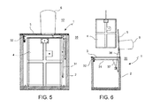
- the device 1 comprises a safety platform 31 connected to the lower housing 2 and movable from a rest position ( Figure 5 ) away from the upper opening 3 and not interfering with the waste container 4 inside the lower housing 2, to a work position ( Figures 6 , 7 ) covering the upper opening 3, and a safety lock 32 for locking the safety platform 31 in the work position and releasing it therefrom, wherein the safety lock 32 comprises at least one foot actuated member 33, e.g. lever, push button etc., arranged to be accessible by an operators' foot near an edge 34 of the upper opening 3, preferably on a rear side 35 of the device 1 opposite the front side 12 of the insertion column 6.
- the safety lock 32 comprises at least one foot actuated member 33, e.g. lever, push button etc., arranged to be accessible by an operators' foot near an edge 34 of the upper opening 3, preferably on a rear side 35 of the device 1 opposite the front side 12 of the insertion column 6.
- the cover platform 5 may be hinged to the lower housing 2, preferably on a front side thereof corresponding to the front side 12 of the insertion column 6 (compare figures 6 , 7 ).
- a spring or a spring-damper-unit or damper 36 may be connected between the lower housing 2 and the cover platform 5 to at least partially counteract the weight of the cover platform 5 and insertion column 6 and for damping its closing movement.
- the safety platform 31 is arranged inside the lower housing 2 and may be hinged to the lower housing 2 on the same side of the cover platform 5 hinge connection.
- the safety platform 31 is preferably permanently biased towards the work position, e.g. by a spring or a spring-damper-unit 37 connected between the lower housing 2 and the safety platform 31.
- a spring or a spring-damper-unit 37 connected between the lower housing 2 and the safety platform 31.
- the safety lock 32 is provided on a side of the lower housing 2 opposite the hinge of the safety platform 31 in order to achieve a safe double sided "simple beam" support without additional constraints which could lead to problems in case of deformations occurring during normal use of the device.
- the safety lock 32 comprises at least one, preferably 2 latch members 38 connected to the lower housing in a position adapted for engaging the safety platform 31 in the work position and movable, e.g. rotatable, from a release position ( Figures 10A, 10B ) to a locking position ( Figures 11A, 11B ) and vice versa.
- Each latch member 38 forms a lower bar 39 and an upper bar 40 shaped to embrace a free edge of the safety platform 31 both from below and from above when the latch member 38 is in the locking position and to withdraw completely from the safety platform 31 when the latch member 38 is in the release position.
- a synchronization mechanism e.g. a synchronization linkage 41 ( figures 9 , 10A, 11A ) or a synchronization gear 42( figures 10A, 11A ), such that the synchronized latch members 38 are all necessarily either in the locking position or in the release position.
- the foot actuated member 33 is connected to the latch member/s 38, e.g. to the synchronization mechanism 41, 42 to provide foot actuated movement of the latch member/s 38 from the locking position to the release position and viceversa.
- the foot actuated member 33 is an elongated lever portion of the synchronization linkage 41.
Landscapes
- Engineering & Computer Science (AREA)
- Mechanical Engineering (AREA)
- Refuse Receptacles (AREA)
- Processing Of Solid Wastes (AREA)
Abstract
a cover platform (5) for opening and closing the upper opening (3), an insertion column (6) mounted on the cover platform (5) and having an insertion aperture (7) for receiving garbage and guiding it into the waste container (4) in the lower housing (2), a lid (10) for covering and opening the insertion aperture (7), a lid actuation mechanism (13) arranged inside an external housing (14) of the insertion column (6) and inaccessible during use of the device (1).
Description
- The present invention relates, in general, to the field underground waste container systems. More particularly, it relates to underground waste container devices for urban environments of the type comprising:
- a lower housing intended to be at least partially placed in the ground and having an upper opening,
- a waste container which can be placed into and extracted from the lower housing through the upper opening,
- a cover platform for opening and closing the upper opening,
- an insertion column mounted on the cover platform and having an insertion aperture above ground level and a passage channel extending from the insertion aperture through the cover platform,
- These known underground waste container systems have multiple drawbacks.
- One drawback is related with the manual opening and closing of the insertion aperture during placement of garbage in the insertion column, since there is usually no possibility to wash or disinfect one's hand afterwards. Also under very cold or hot weather conditions, the manual opening or closing of the insertion aperture can cause frost bits or burns of the users hands. A further disadvantage of the known underground waste container devices is that an electrical power supply for auxiliary functions, like waste filling level sensing, lighting, automatic alert of fault or anomaly situations, etc., needs either a connection to the electrical mains grid or a replaceable and/or rechargeable battery pack.
- However, an electrical mains grid connection to neighboring facilities may be not always available or too far away or not agreed upon by the proprietor, whereas frequent replacement or recharging of batteries is expensive.
- A yet further disadvantage of the known underground waste container devices is a rather complex and labor intensive emptying procedure of the waste container. There are known systems in which a security platform is provided which closes provisional the upper opening of the lower housing when the cover platform is removed therefrom and the waste container is hoisted out for emptying. The security platform is locked in its closing position by a mechanism with a button which is switched to an unlocked position upon insertion of the waste container. However, due to the necessary tolerances (the dimensions of the underground housing may be in the range of 2m x 2m x 4m) and the bad visual conditions at night time (when the waste containers are emptied), unlocking of the security platform often involves an undesirably high number of attempts of placement and insertion of the waste container for the locking mechanism to be released.
- A yet further issue with underground waste container devices is the level of safety provided for preventing a person or an object from falling into the lower housing and for preventing injury of operators involved with the emptying of the waste container.
- The object of the present invention is therefore to provide an improved underground waste container device which better addresses at least some of the described needs.
- A further object of the invention is to provide an underground waste container device which is improved with regard to user friendliness, safety, environmental sustainability.
- These and other objects are achieved by an underground waste container device according to
claim 1. - Advantageous embodiments are the object of the dependent claims.
- According to an aspect of the invention, an underground waste container device comprises:
- a lower housing intended to be at least partially placed in the ground and having an upper opening,
- a waste container which can be placed into and extracted from the lower housing through the upper opening,
- a cover platform for opening and closing the upper opening,
- an insertion column mounted on the cover platform and having an insertion aperture above ground level and a passage channel extending from the insertion aperture through the cover platform, such that garbage inserted through the insertion aperture falls through the passage channel into the waste container inside the lower housing,
- a lid connected to the insertion column and movable in an open position away from the insertion aperture and in a closed position covering the insertion aperture,
- a pedal arranged to be accessible by a users' foot from a front side of the insertion column near the cover platform, and a lid actuating mechanism connected between the pedal and the lid such that actuation of the pedal moves the lid in the open position and release of the pedal automatically moves the lid back in the closed position,
- Thanks to the food operable lid opening, the users hands are no longer required to touch potentially dirty, cold or hot surfaces. Moreover, the inaccessibility of the lid actuating mechanism drastically reduces the number of accessible moving parts and, hence the risk of injury, damage or soiling of users and of the mechanism itself.
- In accordance with a further aspect of the invention, the device comprises a rechargeable battery for energizing electrical auxiliary functions, and an electric generator for recharging the battery, wherein the electric generator is electrically connected to the battery and mechanically associated to one of the lid, lid actuation mechanism and pedal and configured to generate electrical current in response to the movement of the lid.
- This allows to obviate both a mains grid connection and replacement and recharge costs of the batteries and simplifies battery positioning within the device, as frequent accessibility is no longer required,
- In accordance with a further aspect of the invention, the device comprises a safety platform connected to the lower housing and movable from a rest position away from the upper opening and not interfering with the waste container inside the lower housing, to a work position covering the upper opening, and a safety lock for locking the safety platform in the work position and releasing it therefrom, wherein the safety lock comprises at least one foot actuated member arranged to be accessible by an operators foot near an edge of the upper opening.
- This allows the operator to quickly lock and unlock the safety platform using his foot, thereby keeping his hands free to hold and operate a remote control for controlling the crane that empties and moves the hoisted waste container.
- These and other features and advantages of the present invention shall be made apparent from the accompanying drawings which illustrate embodiments of the invention, and, together with the general description of the invention given above, and the detailed description of the embodiments given below, serve to explain the principles of the present invention.
-
Fig. 1 is a perspective view of an underground waste container system according to an embodiment of the invention, -
Fig. 2 is a perspective view of the underground waste container system infigure 1 , in which side walls of a lower housing are removed to better view a waste container and a safety platform, -
Figs. 3, 4 are schematic vertical cross-sectional views of an insertion column of the device, illustrating a lid actuating mechanism and a battery charging electric generator in accordance with embodiments, -
Fig. 5 is a vertical cross-sectional view of the device in accordance with an embodiment in operational conditions, -
Fig. 6 is a vertical cross-sectional view of the device in accordance with an embodiment during hoisting and emptying the waste container, -
Fig. 7 is a perspective view of the device in accordance with an embodiment during hoisting and emptying the waste container, -
Fig. 8 is a magnified view of a detail infigure 6 , -
Fig. 9 is a perspective view of a safety lock of the device in accordance with an embodiment, -
Figs. 10a and 10b are frontal and upper views of the safety lock infigure 9 in release position, -
Figs. 11a and 11b are frontal and upper views of the safety lock infigure 9 in a lock position, -
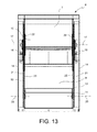
Fig. 13 is a vertical cross-sectional view of a insertion column of the underground waste container device in accordance with an embodiment. - With reference to the figures, an underground
waste container device 1 comprises alower housing 2, e.g. in reinforced concrete, intended to be at least partially placed in the ground and having anupper opening 3, awaste container 4, e.g. in plastics material, which can be placed into and extracted from thelower housing 2 through theupper opening 3, acover platform 5 for opening and closing theupper opening 3, aninsertion column 6 mounted on thecover platform 5 and having aninsertion aperture 7 aboveground level 8 and apassage channel 9 extending from theinsertion aperture 7 through thecover platform 5, such that garbage inserted through theinsertion aperture 7 falls through thepassage channel 9 into thewaste container 4 inside thelower housing 2. - A
lid 10 is connected to theinsertion column 6 and movable in an open position (Figure 4 ) away from theinsertion aperture 7 and in a closed position (Figure 3 ) covering theinsertion aperture 7. - A
pedal 11 is arranged to be accessible by a users' foot from afront side 12 of theinsertion column 6 near thecover platform 5, and alid actuating mechanism 13 is connected between thepedal 11 and thelid 10 such that actuation of thepedal 11 moves thelid 10 in the open position and release of thepedal 11 automatically moves thelid 10 back in the closed position. - Advantageously, the
lid actuation mechanism 13 is arranged inside anexternal housing 14 of the insertion column and inaccessible during use of thedevice 1. - Thanks to the food operable opening of the
lid 10, the users' hands are no longer required to touch potentially dirty, cold or hot surfaces. Moreover, the inaccessibility of thelid actuating mechanism 13 drastically reduces the number of accessible moving parts and, hence the risk of injury, damage or soiling of the user and of the mechanism itself. - In accordance with an embodiment, the
lid 10 may have also ahandle 15 for possible manual operation and is rotatably connected to (preferably twoopposite side walls 16 of) theinsertion column 6 for rotating with respect to theinsertion column 6 about alid rotation axis 17 between the open and closed position. - The
pedal 11 comprises afrontal bar 18 extending outside theinsertion column 6 or in a frontal cavity thereof which is freely accessible by a users' foot and twolateral lever arms 19 extending from opposite ends of thefrontal bar 18 and rotatably connected to the insertion column 6 (preferably near arear wall 20 thereof opposite the frontal bar 18), for rotating with respect to theinsertion column 6 about apedal rotation axis 20. - The
lid actuating mechanism 13 comprises one or twotransmission rods 21 having a first end rotatably connected to thelid 10 in a point eccentrically with respect to thelid rotation axis 17 and a second end connected to the pedal 11 (particularly to the lever arms 13) in a point eccentrically with respect to thepedal rotation axis 20. Moreover, a return spring or acounter weight 22 may be provided connected to the lid eccentrically to thelid rotation axis 17 such as to permanently urge thelid 10 back to the closed position. - The entire
lid actuation mechanism 13 andcounterweight 22 or return spring (if provided) are preferably arranged in agap 23 between theexternal housing 14 and aninternal wall 23 of theinsertion column 6 which forms thepassage channel 9. - In accordance with a further embodiment, the
device 1 may comprise arechargeable battery 28 or battery pack for energizing electrical auxiliary functions, e.g. waste filling level sensing means 24, lighting means 25, display or alert means 26, etc., and anelectric generator 27 for recharging thebattery 28, wherein theelectric generator 27 is electrically connected to thebattery 28 and mechanically associated to one of thelid 10,lid actuation mechanism 13 andpedal 11 and configured to generate electrical current in response to the movement of thelid 10. - This allows to obviate both a mains grid connection and replacement and recharge costs of the batteries and simplifies battery positioning within the
device 1, as frequent accessibility is no longer required. - In accordance with an embodiment, the
lid 10 forms a circular arch shapedtoothed segment 29 meshing with agear 30 of a rotor of theelectric generator 27, with or without the interposition of an additional reducer gear box. Alternatively, thelid 10 may transmit its rotary motion to the rotor of theelectric generator 27 by means of a (not illustrated) pulley - belt transmission. - In accordance with a further embodiment, the
device 1 comprises asafety platform 31 connected to thelower housing 2 and movable from a rest position (Figure 5 ) away from theupper opening 3 and not interfering with thewaste container 4 inside thelower housing 2, to a work position (Figures 6 ,7 ) covering theupper opening 3, and asafety lock 32 for locking thesafety platform 31 in the work position and releasing it therefrom, wherein thesafety lock 32 comprises at least one foot actuatedmember 33, e.g. lever, push button etc., arranged to be accessible by an operators' foot near anedge 34 of theupper opening 3, preferably on arear side 35 of thedevice 1 opposite thefront side 12 of theinsertion column 6. - This allows the operator to quickly lock and unlock the
safety platform 31 using his foot, thereby keeping his hands free to hold and operate a remote control for controlling the crane that empties and moves the hoistedwaste container 4. - In an embodiment, the
cover platform 5 may be hinged to thelower housing 2, preferably on a front side thereof corresponding to thefront side 12 of the insertion column 6 (comparefigures 6 ,7 ). Moreover, a spring or a spring-damper-unit ordamper 36 may be connected between thelower housing 2 and thecover platform 5 to at least partially counteract the weight of thecover platform 5 andinsertion column 6 and for damping its closing movement. Thesafety platform 31 is arranged inside thelower housing 2 and may be hinged to thelower housing 2 on the same side of thecover platform 5 hinge connection. - The
safety platform 31 is preferably permanently biased towards the work position, e.g. by a spring or a spring-damper-unit 37 connected between thelower housing 2 and thesafety platform 31. In this way, when thesafety lock 32 is released and the waist container is lowered into thelower housing 2 it pushes thesafety platform 31 away from theupper opening 3 into the rest position, e.g, adjacent to a side wall or to a bottom wall of thelower housing 2, and when thewaist container 4 is hoisted out of thelower housing 2 thesafety platform 31 finds the space to move automatically back in the work position where it covers theupper opening 3. - in accordance with an embodiment, the
safety lock 32 is provided on a side of thelower housing 2 opposite the hinge of thesafety platform 31 in order to achieve a safe double sided "simple beam" support without additional constraints which could lead to problems in case of deformations occurring during normal use of the device. - The
safety lock 32 comprises at least one, preferably 2latch members 38 connected to the lower housing in a position adapted for engaging thesafety platform 31 in the work position and movable, e.g. rotatable, from a release position (Figures 10A, 10B ) to a locking position (Figures 11A, 11B ) and vice versa. Eachlatch member 38 forms alower bar 39 and anupper bar 40 shaped to embrace a free edge of thesafety platform 31 both from below and from above when thelatch member 38 is in the locking position and to withdraw completely from thesafety platform 31 when thelatch member 38 is in the release position. - In case there are two or
more latch members 38, their position and movement with respect to thelower housing 2 are preferably synchronized by a synchronization mechanism, e.g. a synchronization linkage 41 (figures 9 ,10A, 11A ) or a synchronization gear 42(figures 10A, 11A ), such that thesynchronized latch members 38 are all necessarily either in the locking position or in the release position. - The foot actuated
member 33 is connected to the latch member/s 38, e.g. to thesynchronization mechanism - Particularly, the foot actuated
member 33 is an elongated lever portion of thesynchronization linkage 41. - This provides a particularly safe, simple and reliable locking and release system which obviates many of the drawbacks of the prior art devices.
- While the present invention has been illustrated by description of several embodiments and while the illustrative embodiments have been described in considerate detail, it is not the intention to restrict or in any way limit the scope of the appended claims to such detail. Additional advantages and modifications may readily appear to those skilled in the art.
Claims (14)
- Underground waste container device (1), comprising:- a lower housing (2) intended to be at least partially placed in the ground and having an upper opening (3),- a waste container (4) which can be placed into and extracted from the lower housing (2) through the upper opening (3),- a cover platform (5) for opening and closing the upper opening (3),- an insertion column (6) mounted on the cover platform (5) and having an insertion aperture (7) and a passage channel (9) extending from the insertion aperture (7) through the cover platform (5), such that garbage inserted through the insertion aperture (7) falls through the passage channel (9) into the waste container (4) inside the lower housing (2),- a lid (10) connected to the insertion column (6) and movable in an open position away from the insertion aperture (7) and in a closed position covering the insertion aperture (7),- a pedal (11) arranged to be accessible by a users' foot from a front side (12) of the insertion column (6) near the cover platform (5), and a lid actuating mechanism (13) connected between the pedal (11) and the lid (10) such that actuation of the pedal (11) moves the lid (10) in the open position and release of the pedal (11) automatically moves the lid (10) back in the closed position,
wherein the lid actuation mechanism (13) is arranged inside an external housing (14) of the insertion column (6) and inaccessible during use of the device (1). - Underground waste container device (1) according to claim 1, wherein:- the lid (10) has a handle (15) for manual operation and is rotatably connected to the insertion column (6) for rotating with respect to the insertion column (6) about a lid rotation axis (17) between the open and closed position.- the pedal (11) comprises a frontal bar (18) extending outside the insertion column (6) or in a frontal cavity thereof which is freely accessible by a users' foot, and two lateral lever arms (19) extending from opposite ends of the frontal bar (18) and rotatably connected to the insertion column (6) for rotating with respect to the insertion column (6) about a pedal rotation axis (20),- the lid actuating mechanism (13) comprises at least one transmission rod (21) having a first end rotatable connected to the lid (10) in a point eccentrically with respect to the lid rotation axis (17) and a second end connected to the pedal (11) in a point eccentrically with respect to the pedal rotation axis (20),- return urging means connected to the lid eccentrically to the lid rotation axis (17) such as to permanently urge the lid (10) back to the closed position.
- Underground waste container device (1) according to claim 2, wherein the entire lid actuation mechanism (13) and return urging means (22) are arranged in a gap (23) between the external housing (14) and an internal wall (23) forming the passage channel (9)
- Underground waste container device (1) according to any preceding claim, comprising a rechargeable battery (28) for energizing electrical auxiliary functions and an electric generator (27) for recharging the battery (28), wherein the electric generator (27) is electrically connected to the battery (28) and mechanically associated to one of the lid (10), lid actuation mechanism (13) and pedal (11) and configured to generate electrical current in response to the movement of the lid (10).
- Underground waste container device (1) according to claim 4, wherein the lid (10) forms a toothed segment (29) meshing with a gear (30) of a rotor of the electric generator (27), with or without the interposition of an additional reducer gear box.
- Underground waste container device (1) according to any preceding claim, comprising:- a safety platform (31) connected to the lower housing (2) and movable from a rest position away from the upper opening (3) and not interfering with the waste container (4) inside the lower housing (2), to a work position covering the upper opening (3), and- a safety lock (32) for locking the safety platform (31) in the work position and releasing it therefrom, wherein the safety lock (32) comprises at least one foot actuated member (33) arranged to be accessible by an operators' foot near an edge (34) of the upper opening (3).
- Underground waste container device (1) according to claim 6, wherein the cover platform (5) is hinged to the lower housing (2) and one of:- a spring, or- a spring-damper-unit, or- a damper (36),
is connected between the lower housing (2) and the cover platform (5) to at least partially counteract the weight of the cover platform (5) and insertion column (6) and for damping its closing movement. - Underground waste container device (1) according to claim 6 or 7, wherein the safety platform (31) is arranged inside the lower housing (2) and hinged to the lower housing (2) on the same side as the the cover platform (5),
wherein one of:- a spring, or- a spring-damper-unit (37)is connected between the lower housing (2) and the safety platform (31) to permanently bias the safety platform (31) towards the work position, such that:- when the safety lock (32) is released and the waist container is lowered into the lower housing (2) it pushes the safety platform (31) away from the upper opening (3) into the rest position, and- when the waist container (4) is hoisted out of the lower housing (2), the safety platform (31) finds the space to move automatically back in the work position where it covers the upper opening (3). - Underground waste container device (1) according to claim 8, wherein the safety lock (32) is provided on a side of the lower housing (2) opposite the hinge of the safety platform (31).
- Underground waste container device (1) according to any one of claims 6 to 9, in which the safety lock (32) comprises at least one latch member (38) connected to the lower housing (2) in a position adapted for engaging the safety platform (31) in the work position and movable from a release position to a locking position and vice versa,
said latch member (38) forming a lower bar (39) and an upper bar (40) shaped to embrace a free edge of the safety platform (31) both from below and from above when the latch member (38) is in the locking position and to withdraw completely from the safety platform (31) when the latch member (38) is in the release position. - Underground waste container device (1) according to claim 10, in which at least two of said latch members (38) are provided and their position and movement with respect to the lower housing (2) are synchronized by a synchronization mechanism (41), such that the latch members (38) are all necessarily either in the locking position or in the release position.
- Underground waste container device (1) according to claim 11. wherein the foot actuated member (33) is connected to one of the latch member/s (38) and the synchronization mechanism (41, 42).
- Underground waste container device (1) according to claim 11 or 12, wherein said synchronization mechanism (41) comprises a synchronization linkage or a synchronization gear (42).
- Underground waste container device (1) according to claim 13, wherein the foot actuated member (33) is an elongated lever portion of the synchronization linkage (41).
Priority Applications (2)
| Application Number | Priority Date | Filing Date | Title |
|---|---|---|---|
| EP13174633.1A EP2821352B1 (en) | 2013-07-02 | 2013-07-02 | Underground waste container, particularly for use in urban environments |
| HRP20170068TT HRP20170068T1 (en) | 2013-07-02 | 2017-01-17 | Underground waste container, particularly for use in urban environments |
Applications Claiming Priority (1)
| Application Number | Priority Date | Filing Date | Title |
|---|---|---|---|
| EP13174633.1A EP2821352B1 (en) | 2013-07-02 | 2013-07-02 | Underground waste container, particularly for use in urban environments |
Publications (2)
| Publication Number | Publication Date |
|---|---|
| EP2821352A1 true EP2821352A1 (en) | 2015-01-07 |
| EP2821352B1 EP2821352B1 (en) | 2016-10-26 |
Family
ID=48782180
Family Applications (1)
| Application Number | Title | Priority Date | Filing Date |
|---|---|---|---|
| EP13174633.1A Active EP2821352B1 (en) | 2013-07-02 | 2013-07-02 | Underground waste container, particularly for use in urban environments |
Country Status (2)
| Country | Link |
|---|---|
| EP (1) | EP2821352B1 (en) |
| HR (1) | HRP20170068T1 (en) |
Cited By (7)
| Publication number | Priority date | Publication date | Assignee | Title |
|---|---|---|---|---|
| RU175741U1 (en) * | 2016-11-25 | 2017-12-18 | Общество с ограниченной ответственностью "СПЕЦТРАНС" | DEPTH TYPE CONTAINER FOR COLLECTING SOLID DOMESTIC WASTE |
| CN107738846A (en) * | 2017-10-19 | 2018-02-27 | 唐成吉 | Liftable high capacity garbage storage device |
| CN108313572A (en) * | 2018-02-12 | 2018-07-24 | 广西玉柴专用汽车有限公司 | A kind of underground type refuse collection station |
| CN113844793A (en) * | 2020-06-28 | 2021-12-28 | 沈阳新松机器人自动化股份有限公司 | Intelligent direct-discharging type dustbin |
| IT202200000662A1 (en) * | 2022-03-23 | 2023-09-23 | Greco Ecology S R L | One-way municipal solid waste disposal system with pre-established volume |
| WO2024141373A1 (en) * | 2022-12-28 | 2024-07-04 | Tomra Systems Asa | System for collecting used food and beverage containers |
| EP4534445A1 (en) | 2023-10-06 | 2025-04-09 | Astech | Waste container with volume-calibrated waste introduction system |
Citations (7)
| Publication number | Priority date | Publication date | Assignee | Title |
|---|---|---|---|---|
| EP0915034A1 (en) * | 1997-11-07 | 1999-05-12 | Maturi e Sampietro S.A. | Inlet mouth for depositing refuse inside a collection unit |
| EP1508535A1 (en) * | 2003-08-20 | 2005-02-23 | Bruno Perlini | Apparatus for sorted waste collection |
| ES2244280A1 (en) * | 2003-04-24 | 2005-12-01 | Resolur Tecnicos R.S.U., Sl. | Buried container for solid urban waste has inner cover for closing storage device when outer cover is opened to prevent escape of bad odors |
| ES2301315A1 (en) * | 2005-11-30 | 2008-06-16 | Mbe Sotkon, S.L. | Security system for underground containers has retainer for holding covering in operational position such that waste may be collected from container and container may be cleaned and disinfected |
| DE202008015182U1 (en) * | 2008-11-13 | 2010-04-08 | Paul Wolff Gmbh | Automatic cover device |
| EP2316753A1 (en) * | 2009-10-27 | 2011-05-04 | Villiger Entsorgungssysteme AG | Insertion chute for a subterranean waste collection device |
| FR2962424A1 (en) * | 2010-07-07 | 2012-01-13 | Stefano Mondini | Wastes i.e. municipal wastes, collecting device, has locking assembly actuated electrically for allowing opening of door and electrically powered by opening movement of door and/or movement of opening lever |
-
2013
- 2013-07-02 EP EP13174633.1A patent/EP2821352B1/en active Active
-
2017
- 2017-01-17 HR HRP20170068TT patent/HRP20170068T1/en unknown
Patent Citations (7)
| Publication number | Priority date | Publication date | Assignee | Title |
|---|---|---|---|---|
| EP0915034A1 (en) * | 1997-11-07 | 1999-05-12 | Maturi e Sampietro S.A. | Inlet mouth for depositing refuse inside a collection unit |
| ES2244280A1 (en) * | 2003-04-24 | 2005-12-01 | Resolur Tecnicos R.S.U., Sl. | Buried container for solid urban waste has inner cover for closing storage device when outer cover is opened to prevent escape of bad odors |
| EP1508535A1 (en) * | 2003-08-20 | 2005-02-23 | Bruno Perlini | Apparatus for sorted waste collection |
| ES2301315A1 (en) * | 2005-11-30 | 2008-06-16 | Mbe Sotkon, S.L. | Security system for underground containers has retainer for holding covering in operational position such that waste may be collected from container and container may be cleaned and disinfected |
| DE202008015182U1 (en) * | 2008-11-13 | 2010-04-08 | Paul Wolff Gmbh | Automatic cover device |
| EP2316753A1 (en) * | 2009-10-27 | 2011-05-04 | Villiger Entsorgungssysteme AG | Insertion chute for a subterranean waste collection device |
| FR2962424A1 (en) * | 2010-07-07 | 2012-01-13 | Stefano Mondini | Wastes i.e. municipal wastes, collecting device, has locking assembly actuated electrically for allowing opening of door and electrically powered by opening movement of door and/or movement of opening lever |
Cited By (9)
| Publication number | Priority date | Publication date | Assignee | Title |
|---|---|---|---|---|
| RU175741U1 (en) * | 2016-11-25 | 2017-12-18 | Общество с ограниченной ответственностью "СПЕЦТРАНС" | DEPTH TYPE CONTAINER FOR COLLECTING SOLID DOMESTIC WASTE |
| CN107738846A (en) * | 2017-10-19 | 2018-02-27 | 唐成吉 | Liftable high capacity garbage storage device |
| CN107738846B (en) * | 2017-10-19 | 2020-06-12 | 浙江凯邦鞋业有限公司 | Lifting type large-capacity garbage storage device |
| CN108313572A (en) * | 2018-02-12 | 2018-07-24 | 广西玉柴专用汽车有限公司 | A kind of underground type refuse collection station |
| CN113844793A (en) * | 2020-06-28 | 2021-12-28 | 沈阳新松机器人自动化股份有限公司 | Intelligent direct-discharging type dustbin |
| IT202200000662A1 (en) * | 2022-03-23 | 2023-09-23 | Greco Ecology S R L | One-way municipal solid waste disposal system with pre-established volume |
| WO2024141373A1 (en) * | 2022-12-28 | 2024-07-04 | Tomra Systems Asa | System for collecting used food and beverage containers |
| EP4534445A1 (en) | 2023-10-06 | 2025-04-09 | Astech | Waste container with volume-calibrated waste introduction system |
| FR3153812A1 (en) * | 2023-10-06 | 2025-04-11 | Astech | Waste container with volume-calibrated waste introduction system |
Also Published As
| Publication number | Publication date |
|---|---|
| HRP20170068T1 (en) | 2017-03-24 |
| EP2821352B1 (en) | 2016-10-26 |
Similar Documents
| Publication | Publication Date | Title |
|---|---|---|
| EP2821352B1 (en) | Underground waste container, particularly for use in urban environments | |
| EP2344403B1 (en) | System with SUBSURFACE SYSTEM FOR THE COLLECTION OF REFUSE | |
| EP3523195B1 (en) | Compactor trolley for aeronautical applications | |
| CN108879386A (en) | A kind of power distribution cabinet | |
| BR112015014276B1 (en) | control system, including a fixed emergency stop button and a mobile emergency stop button | |
| JP2014072951A (en) | Battery charging locker | |
| CN206685783U (en) | A kind of rural power grids distribution box multifunctional operating arm | |
| CN205543803U (en) | Operating axis and back door interlock of cubical switchboard | |
| CN106368519A (en) | Intelligent locking system | |
| CN109659823B (en) | Anti-theft power distribution cabinet | |
| KR20130102803A (en) | One touch door lock | |
| JP6043557B2 (en) | Garbage storage with a simple toilet | |
| IT201800004106A1 (en) | LOCKING GROUP WITH SAFETY DEVICE FOR MANUAL UNLOCKING OF DOORS OR DRAWERS. | |
| CN105390947A (en) | Switch cabinet | |
| CN203647478U (en) | Safe box for operating scalpels | |
| KR20100011544U (en) | Built-in type multi trash box | |
| CN202495369U (en) | Interlock of distribution cabinet | |
| KR100922869B1 (en) | Underground distribution box associated with an electric manhole. | |
| RU43409U1 (en) | CABINET OF COMPLETE DISTRIBUTION DEVICE | |
| CN206789454U (en) | A kind of locking mechanism of total air switch | |
| CN208316055U (en) | A kind of electrical cabinet of the automatically controlled protective cover of band | |
| CN206976858U (en) | A kind of elevator power supply box | |
| EP1835114A2 (en) | Automatic mechanism for moving a bar | |
| KR100704428B1 (en) | Distribution structure of public housing with increased power saving efficiency | |
| CN206541768U (en) | A kind of isolation switch covers case |
Legal Events
| Date | Code | Title | Description |
|---|---|---|---|
| PUAI | Public reference made under article 153(3) epc to a published international application that has entered the european phase |
Free format text: ORIGINAL CODE: 0009012 |
|
| 17P | Request for examination filed |
Effective date: 20130702 |
|
| AK | Designated contracting states |
Kind code of ref document: A1 Designated state(s): AL AT BE BG CH CY CZ DE DK EE ES FI FR GB GR HR HU IE IS IT LI LT LU LV MC MK MT NL NO PL PT RO RS SE SI SK SM TR |
|
| AX | Request for extension of the european patent |
Extension state: BA ME |
|
| R17P | Request for examination filed (corrected) |
Effective date: 20150630 |
|
| RAX | Requested extension states of the european patent have changed |
Extension state: ME Payment date: 20150630 Extension state: BA Payment date: 20150630 |
|
| RBV | Designated contracting states (corrected) |
Designated state(s): AL AT BE BG CH CY CZ DE DK EE ES FI FR GB GR HR HU IE IS IT LI LT LU LV MC MK MT NL NO PL PT RO RS SE SI SK SM TR |
|
| GRAP | Despatch of communication of intention to grant a patent |
Free format text: ORIGINAL CODE: EPIDOSNIGR1 |
|
| INTG | Intention to grant announced |
Effective date: 20160520 |
|
| GRAS | Grant fee paid |
Free format text: ORIGINAL CODE: EPIDOSNIGR3 |
|
| GRAA | (expected) grant |
Free format text: ORIGINAL CODE: 0009210 |
|
| AK | Designated contracting states |
Kind code of ref document: B1 Designated state(s): AL AT BE BG CH CY CZ DE DK EE ES FI FR GB GR HR HU IE IS IT LI LT LU LV MC MK MT NL NO PL PT RO RS SE SI SK SM TR |
|
| AX | Request for extension of the european patent |
Extension state: BA ME |
|
| REG | Reference to a national code |
Ref country code: GB Ref legal event code: FG4D |
|
| REG | Reference to a national code |
Ref country code: CH Ref legal event code: EP |
|
| REG | Reference to a national code |
Ref country code: AT Ref legal event code: REF Ref document number: 839833 Country of ref document: AT Kind code of ref document: T Effective date: 20161115 |
|
| REG | Reference to a national code |
Ref country code: IE Ref legal event code: FG4D |
|
| REG | Reference to a national code |
Ref country code: DE Ref legal event code: R096 Ref document number: 602013013146 Country of ref document: DE |
|
| REG | Reference to a national code |
Ref country code: HR Ref legal event code: TUEP Ref document number: P20170068 Country of ref document: HR |
|
| REG | Reference to a national code |
Ref country code: LT Ref legal event code: MG4D |
|
| PG25 | Lapsed in a contracting state [announced via postgrant information from national office to epo] |
Ref country code: LV Free format text: LAPSE BECAUSE OF FAILURE TO SUBMIT A TRANSLATION OF THE DESCRIPTION OR TO PAY THE FEE WITHIN THE PRESCRIBED TIME-LIMIT Effective date: 20161026 |
|
| REG | Reference to a national code |
Ref country code: NL Ref legal event code: MP Effective date: 20161026 |
|
| REG | Reference to a national code |
Ref country code: AT Ref legal event code: MK05 Ref document number: 839833 Country of ref document: AT Kind code of ref document: T Effective date: 20161026 |
|
| REG | Reference to a national code |
Ref country code: HR Ref legal event code: T1PR Ref document number: P20170068 Country of ref document: HR |
|
| PG25 | Lapsed in a contracting state [announced via postgrant information from national office to epo] |
Ref country code: SE Free format text: LAPSE BECAUSE OF FAILURE TO SUBMIT A TRANSLATION OF THE DESCRIPTION OR TO PAY THE FEE WITHIN THE PRESCRIBED TIME-LIMIT Effective date: 20161026 Ref country code: NO Free format text: LAPSE BECAUSE OF FAILURE TO SUBMIT A TRANSLATION OF THE DESCRIPTION OR TO PAY THE FEE WITHIN THE PRESCRIBED TIME-LIMIT Effective date: 20170126 Ref country code: GR Free format text: LAPSE BECAUSE OF FAILURE TO SUBMIT A TRANSLATION OF THE DESCRIPTION OR TO PAY THE FEE WITHIN THE PRESCRIBED TIME-LIMIT Effective date: 20170127 Ref country code: LT Free format text: LAPSE BECAUSE OF FAILURE TO SUBMIT A TRANSLATION OF THE DESCRIPTION OR TO PAY THE FEE WITHIN THE PRESCRIBED TIME-LIMIT Effective date: 20161026 |
|
| PG25 | Lapsed in a contracting state [announced via postgrant information from national office to epo] |
Ref country code: RS Free format text: LAPSE BECAUSE OF FAILURE TO SUBMIT A TRANSLATION OF THE DESCRIPTION OR TO PAY THE FEE WITHIN THE PRESCRIBED TIME-LIMIT Effective date: 20161026 Ref country code: FI Free format text: LAPSE BECAUSE OF FAILURE TO SUBMIT A TRANSLATION OF THE DESCRIPTION OR TO PAY THE FEE WITHIN THE PRESCRIBED TIME-LIMIT Effective date: 20161026 Ref country code: PL Free format text: LAPSE BECAUSE OF FAILURE TO SUBMIT A TRANSLATION OF THE DESCRIPTION OR TO PAY THE FEE WITHIN THE PRESCRIBED TIME-LIMIT Effective date: 20161026 Ref country code: AT Free format text: LAPSE BECAUSE OF FAILURE TO SUBMIT A TRANSLATION OF THE DESCRIPTION OR TO PAY THE FEE WITHIN THE PRESCRIBED TIME-LIMIT Effective date: 20161026 Ref country code: NL Free format text: LAPSE BECAUSE OF FAILURE TO SUBMIT A TRANSLATION OF THE DESCRIPTION OR TO PAY THE FEE WITHIN THE PRESCRIBED TIME-LIMIT Effective date: 20161026 Ref country code: PT Free format text: LAPSE BECAUSE OF FAILURE TO SUBMIT A TRANSLATION OF THE DESCRIPTION OR TO PAY THE FEE WITHIN THE PRESCRIBED TIME-LIMIT Effective date: 20170227 Ref country code: IS Free format text: LAPSE BECAUSE OF FAILURE TO SUBMIT A TRANSLATION OF THE DESCRIPTION OR TO PAY THE FEE WITHIN THE PRESCRIBED TIME-LIMIT Effective date: 20170226 Ref country code: BE Free format text: LAPSE BECAUSE OF FAILURE TO SUBMIT A TRANSLATION OF THE DESCRIPTION OR TO PAY THE FEE WITHIN THE PRESCRIBED TIME-LIMIT Effective date: 20161026 Ref country code: ES Free format text: LAPSE BECAUSE OF FAILURE TO SUBMIT A TRANSLATION OF THE DESCRIPTION OR TO PAY THE FEE WITHIN THE PRESCRIBED TIME-LIMIT Effective date: 20161026 |
|
| REG | Reference to a national code |
Ref country code: DE Ref legal event code: R097 Ref document number: 602013013146 Country of ref document: DE |
|
| PG25 | Lapsed in a contracting state [announced via postgrant information from national office to epo] |
Ref country code: CZ Free format text: LAPSE BECAUSE OF FAILURE TO SUBMIT A TRANSLATION OF THE DESCRIPTION OR TO PAY THE FEE WITHIN THE PRESCRIBED TIME-LIMIT Effective date: 20161026 Ref country code: SK Free format text: LAPSE BECAUSE OF FAILURE TO SUBMIT A TRANSLATION OF THE DESCRIPTION OR TO PAY THE FEE WITHIN THE PRESCRIBED TIME-LIMIT Effective date: 20161026 Ref country code: DK Free format text: LAPSE BECAUSE OF FAILURE TO SUBMIT A TRANSLATION OF THE DESCRIPTION OR TO PAY THE FEE WITHIN THE PRESCRIBED TIME-LIMIT Effective date: 20161026 Ref country code: RO Free format text: LAPSE BECAUSE OF FAILURE TO SUBMIT A TRANSLATION OF THE DESCRIPTION OR TO PAY THE FEE WITHIN THE PRESCRIBED TIME-LIMIT Effective date: 20161026 Ref country code: EE Free format text: LAPSE BECAUSE OF FAILURE TO SUBMIT A TRANSLATION OF THE DESCRIPTION OR TO PAY THE FEE WITHIN THE PRESCRIBED TIME-LIMIT Effective date: 20161026 |
|
| PG25 | Lapsed in a contracting state [announced via postgrant information from national office to epo] |
Ref country code: BG Free format text: LAPSE BECAUSE OF FAILURE TO SUBMIT A TRANSLATION OF THE DESCRIPTION OR TO PAY THE FEE WITHIN THE PRESCRIBED TIME-LIMIT Effective date: 20170126 Ref country code: SM Free format text: LAPSE BECAUSE OF FAILURE TO SUBMIT A TRANSLATION OF THE DESCRIPTION OR TO PAY THE FEE WITHIN THE PRESCRIBED TIME-LIMIT Effective date: 20161026 Ref country code: IT Free format text: LAPSE BECAUSE OF FAILURE TO SUBMIT A TRANSLATION OF THE DESCRIPTION OR TO PAY THE FEE WITHIN THE PRESCRIBED TIME-LIMIT Effective date: 20161026 |
|
| PLBE | No opposition filed within time limit |
Free format text: ORIGINAL CODE: 0009261 |
|
| STAA | Information on the status of an ep patent application or granted ep patent |
Free format text: STATUS: NO OPPOSITION FILED WITHIN TIME LIMIT |
|
| 26N | No opposition filed |
Effective date: 20170727 |
|
| PG25 | Lapsed in a contracting state [announced via postgrant information from national office to epo] |
Ref country code: SI Free format text: LAPSE BECAUSE OF FAILURE TO SUBMIT A TRANSLATION OF THE DESCRIPTION OR TO PAY THE FEE WITHIN THE PRESCRIBED TIME-LIMIT Effective date: 20161026 |
|
| REG | Reference to a national code |
Ref country code: CH Ref legal event code: PL |
|
| GBPC | Gb: european patent ceased through non-payment of renewal fee |
Effective date: 20170702 |
|
| REG | Reference to a national code |
Ref country code: IE Ref legal event code: MM4A |
|
| REG | Reference to a national code |
Ref country code: FR Ref legal event code: ST Effective date: 20180330 |
|
| PG25 | Lapsed in a contracting state [announced via postgrant information from national office to epo] |
Ref country code: GB Free format text: LAPSE BECAUSE OF NON-PAYMENT OF DUE FEES Effective date: 20170702 Ref country code: IE Free format text: LAPSE BECAUSE OF NON-PAYMENT OF DUE FEES Effective date: 20170702 Ref country code: CH Free format text: LAPSE BECAUSE OF NON-PAYMENT OF DUE FEES Effective date: 20170731 Ref country code: LI Free format text: LAPSE BECAUSE OF NON-PAYMENT OF DUE FEES Effective date: 20170731 |
|
| PG25 | Lapsed in a contracting state [announced via postgrant information from national office to epo] |
Ref country code: FR Free format text: LAPSE BECAUSE OF NON-PAYMENT OF DUE FEES Effective date: 20170731 |
|
| REG | Reference to a national code |
Ref country code: HR Ref legal event code: ODRP Ref document number: P20170068 Country of ref document: HR Payment date: 20180626 Year of fee payment: 6 |
|
| PG25 | Lapsed in a contracting state [announced via postgrant information from national office to epo] |
Ref country code: LU Free format text: LAPSE BECAUSE OF NON-PAYMENT OF DUE FEES Effective date: 20170702 |
|
| PGFP | Annual fee paid to national office [announced via postgrant information from national office to epo] |
Ref country code: HR Payment date: 20180626 Year of fee payment: 6 |
|
| PG25 | Lapsed in a contracting state [announced via postgrant information from national office to epo] |
Ref country code: MT Free format text: LAPSE BECAUSE OF NON-PAYMENT OF DUE FEES Effective date: 20170702 |
|
| PGFP | Annual fee paid to national office [announced via postgrant information from national office to epo] |
Ref country code: DE Payment date: 20180702 Year of fee payment: 6 |
|
| PG25 | Lapsed in a contracting state [announced via postgrant information from national office to epo] |
Ref country code: HU Free format text: LAPSE BECAUSE OF FAILURE TO SUBMIT A TRANSLATION OF THE DESCRIPTION OR TO PAY THE FEE WITHIN THE PRESCRIBED TIME-LIMIT; INVALID AB INITIO Effective date: 20130702 Ref country code: MC Free format text: LAPSE BECAUSE OF FAILURE TO SUBMIT A TRANSLATION OF THE DESCRIPTION OR TO PAY THE FEE WITHIN THE PRESCRIBED TIME-LIMIT Effective date: 20161026 |
|
| PG25 | Lapsed in a contracting state [announced via postgrant information from national office to epo] |
Ref country code: CY Free format text: LAPSE BECAUSE OF FAILURE TO SUBMIT A TRANSLATION OF THE DESCRIPTION OR TO PAY THE FEE WITHIN THE PRESCRIBED TIME-LIMIT Effective date: 20161026 |
|
| PG25 | Lapsed in a contracting state [announced via postgrant information from national office to epo] |
Ref country code: MK Free format text: LAPSE BECAUSE OF FAILURE TO SUBMIT A TRANSLATION OF THE DESCRIPTION OR TO PAY THE FEE WITHIN THE PRESCRIBED TIME-LIMIT Effective date: 20161026 |
|
| REG | Reference to a national code |
Ref country code: HR Ref legal event code: PBON Ref document number: P20170068 Country of ref document: HR Effective date: 20190702 |
|
| REG | Reference to a national code |
Ref country code: DE Ref legal event code: R119 Ref document number: 602013013146 Country of ref document: DE |
|
| PG25 | Lapsed in a contracting state [announced via postgrant information from national office to epo] |
Ref country code: TR Free format text: LAPSE BECAUSE OF FAILURE TO SUBMIT A TRANSLATION OF THE DESCRIPTION OR TO PAY THE FEE WITHIN THE PRESCRIBED TIME-LIMIT Effective date: 20161026 |
|
| PG25 | Lapsed in a contracting state [announced via postgrant information from national office to epo] |
Ref country code: DE Free format text: LAPSE BECAUSE OF NON-PAYMENT OF DUE FEES Effective date: 20200201 |
|
| PG25 | Lapsed in a contracting state [announced via postgrant information from national office to epo] |
Ref country code: HR Free format text: LAPSE BECAUSE OF NON-PAYMENT OF DUE FEES Effective date: 20190702 |
|
| PG25 | Lapsed in a contracting state [announced via postgrant information from national office to epo] |
Ref country code: AL Free format text: LAPSE BECAUSE OF FAILURE TO SUBMIT A TRANSLATION OF THE DESCRIPTION OR TO PAY THE FEE WITHIN THE PRESCRIBED TIME-LIMIT Effective date: 20161026 |