EP2829827A1 - Refrigerator - Google Patents
Refrigerator Download PDFInfo
- Publication number
- EP2829827A1 EP2829827A1 EP12872109.9A EP12872109A EP2829827A1 EP 2829827 A1 EP2829827 A1 EP 2829827A1 EP 12872109 A EP12872109 A EP 12872109A EP 2829827 A1 EP2829827 A1 EP 2829827A1
- Authority
- EP
- European Patent Office
- Prior art keywords
- fitting member
- gasket
- gasket fitting
- insulating material
- throat
- Prior art date
- Legal status (The legal status is an assumption and is not a legal conclusion. Google has not performed a legal analysis and makes no representation as to the accuracy of the status listed.)
- Withdrawn
Links
Images







Classifications
-
- F—MECHANICAL ENGINEERING; LIGHTING; HEATING; WEAPONS; BLASTING
- F25—REFRIGERATION OR COOLING; COMBINED HEATING AND REFRIGERATION SYSTEMS; HEAT PUMP SYSTEMS; MANUFACTURE OR STORAGE OF ICE; LIQUEFACTION SOLIDIFICATION OF GASES
- F25D—REFRIGERATORS; COLD ROOMS; ICE-BOXES; COOLING OR FREEZING APPARATUS NOT OTHERWISE PROVIDED FOR
- F25D23/00—General constructional features
- F25D23/02—Doors; Covers
-
- F—MECHANICAL ENGINEERING; LIGHTING; HEATING; WEAPONS; BLASTING
- F25—REFRIGERATION OR COOLING; COMBINED HEATING AND REFRIGERATION SYSTEMS; HEAT PUMP SYSTEMS; MANUFACTURE OR STORAGE OF ICE; LIQUEFACTION SOLIDIFICATION OF GASES
- F25D—REFRIGERATORS; COLD ROOMS; ICE-BOXES; COOLING OR FREEZING APPARATUS NOT OTHERWISE PROVIDED FOR
- F25D23/00—General constructional features
- F25D23/08—Parts formed wholly or mainly of plastics materials
- F25D23/082—Strips
- F25D23/087—Sealing strips
-
- F—MECHANICAL ENGINEERING; LIGHTING; HEATING; WEAPONS; BLASTING
- F25—REFRIGERATION OR COOLING; COMBINED HEATING AND REFRIGERATION SYSTEMS; HEAT PUMP SYSTEMS; MANUFACTURE OR STORAGE OF ICE; LIQUEFACTION SOLIDIFICATION OF GASES
- F25D—REFRIGERATORS; COLD ROOMS; ICE-BOXES; COOLING OR FREEZING APPARATUS NOT OTHERWISE PROVIDED FOR
- F25D2201/00—Insulation
- F25D2201/10—Insulation with respect to heat
- F25D2201/14—Insulation with respect to heat using subatmospheric pressure
Definitions
- Embodiments of the present invention relate to a refrigerator.
- a refrigerator includes an insulating box body as a main body of the refrigerator for improving the thermal insulation and achieving the energy saving.
- the insulating box body includes an outer box, an inner box, and an insulating material sandwiched in a space between the outer and inner boxes.
- the refrigerator further includes a door that seals the opening of the insulating box body.
- the door similarly includes an outer plate; an inner plate, and an insulating material sandwiched between the outer plate and the inner plate.
- the insulating materials polyurethane foam is often used. In recent years, vacuum insulating materials are used instead of polyurethane foam in some cases.
- the vacuum insulating materials are formed such that a core material is vacuum-packed with a laminate film of aluminum foil and synthetic resin or with an aluminum-deposited laminate film of synthetic resin and are formed into panels.
- the thickness of the panel of a vacuum insulating material varies from product to product.
- the doors of refrigerators always need to be formed with a fixed thickness.
- to use the panel of a vacuum insulating material as the insulating material there is a need for a structure capable of accommodating varying thickness owing to individual differences of products of the vacuum insulating material.
- An object of the present invention is to provide a refrigerator including a door having a structure capable of accommodating the thickness of the vacuum insulating material varying from product to product.
- a refrigerator includes: an insulating box body in which a space between an inner box and an outer box is filled with an insulating material and an opening is provided at the front; and a door configured to close the opening at the front of the insulating box body.
- the door includes: an outer plate; an inner plate opposed to the outer plate; a vacuum insulating material sandwiched between the outer plate and the inner plate; a gasket attached to an entire circumference of the door in the vicinity of an edge on an inner side of the door; a frame-shaped gasket fitting member to which the gasket is fitted; and a frame-shaped throat member configured to enter an inside of the insulating box body to prevent cold air from flowing out when the door is closed.
- the distance between the outer plate and the gasket fitting member is fixed. Between a front end of the gasket fitting member and a back surface of the vacuum insulating material, a separating space is formed.
- a refrigerator 1 of a first embodiment includes an insulating box body 3 and plural doors 21 to 26.
- the insulating box body 3 is opened at the front, and the inside thereof is partitioned into plural compartments.
- the plural doors 21 to 26 seal front openings of the respective compartments.
- the side where the doors 21 to 26 are provided are referred to as a front side
- the side where the insulating box body 3 is located is referred to as a back side (see Fig. 1 ).
- the insulating box body 3 includes an inner box, an outer box, and vacuum insulating materials 35 sandwiched between the inner and outer boxes as an insulating material.
- the vacuum insulating materials 35 are sandwiched between the substantially entire opposing surfaces of the outer and inner boxes.
- Fig. 2 only the vacuum insulating material 35 of the right-side plate of the refrigerator 1, which is located to the observer's right, is indicated by a dotted line for explanation, but actually, the vacuum insulating material 35 is provided for each of the top, bottom, left-side, and back plates.
- the insulating box body 3 is partitioned into five compartments, for example.
- the five compartments are used as a refrigerating compartment 11, a vegetable compartment 12, an ice compartment 13 and a first freezing compartment 14, that are arranged side by side, and a second freezing compartment 15, which are sequentially arranged from above, for example.
- double door-type refrigerating compartment first and second doors 21 and 22 are attached.
- the doors of the refrigerator 1 also include the vacuum insulating materials 35.
- Each of the vacuum insulating materials 35 is formed in such a manner that an inorganic core material, such as grass wool, is vacuum-packed with a laminate film of aluminum foil and synthetic resin or an aluminum-deposited laminate film of synthetic resin.
- the vacuum insulating materials formed by the aforementioned manufacturing method are difficult to form into strictly fixed thickness because of the manufacturing difficulties and cause individual differences in thickness of products.
- the doors of the refrigerator 1 need to be surely closed air-tightly, and the distance between the outer plate and a gasket fitting member needs to be always fixed.
- the second freezing compartment door 26 is described as a representative door.
- the second freezing compartment door 26 includes an outer plate 31, an inner plate 32, a side frame 33, a gasket fitting member 40, a throat member 34, the vacuum insulating material 35, fasteners 36, a gasket 37, and a handle 39.
- the throat member 34 is joined to the inside of the frame of the gasket fitting member 40 to be integrally formed with the same.
- the outer plate 31 of the second freezing compartment door 26 is fixed near the front end of the side frame 33.
- the gasket fitting member 40 and throat member 34 are fixed near the back end of the side frame 33.
- the inner plate 32 of the second freezing compartment door 26 is provided on the front side of the throat member 34.
- the vacuum insulating material 35 is provided between the outer plate 31 and the inner plate 32.
- the vacuum insulating material 35 has such an area (size) that occupies the substantially entire opposing surfaces of the outer plate 31 and the inner plate 32.
- the gasket 37 is fitted to the back side of the gasket fitting member 40.
- the handle 39 is attached to the front surface of the outer plate 31.
- a soft tape 41 is wound around the circumference of the vacuum insulating material 35.
- the soft tape 41 is made of a material having a heat insulating effect such as sponge tape.
- the front surface of the vacuum insulating material 35 is fixed to the outer plate 31 by bonding or the like.
- the plural fasteners 36 are fixed by bonding or the like.
- each fastener 36 includes a base plate 36a formed into a plate and a cylindrical portion 36b extending backward from the center of the base plate 36a.
- the cylindrical portion 36b includes a threaded hole, in which a later-described screw 42 is screwed.
- the base plate 36a is fixed to the vacuum insulating material 35 by bonding.
- the cylindrical portion 36b penetrates the inner plate 32 and abuts on the edge portion of the throat member 34.
- the screw 42 fixes the edge portion of the throat member 34 to the cylindrical portion 36b.
- the throat member 34, cylindrical portion 36b, and inner plate 32 are provided to satisfy: b-c > a where a is a distance between the portion of the throat member 34 abutting on the fastener 36 and the front end of the gasket fitting member 40; b is a height of the cylindrical portion 36b of the fastener 36; and c is the thickness of the inner plate 32.
- the space within the throat member 34 is previously filled with an insulating material 43 such as polystyrene foam.
- an elastic portion 34k is formed at least one place near the insulating material 43 in the throat member 34.
- the elastic portion 34k is formed into a thin circular shape and is more deformable than the other part around the same.
- the vacuum insulating material 35 is thicker or thinner than designed, the fastener 36 is displaced a little forward or backward, and the fixing position of the edge portion of the throat member 34 (a fastener fixing portion 34b) moves forward or backward. Even in such a case, because of provision of the elastic portion 34k, the elastic portion 34k can deform to move the edge portion of the throat member 34.
- reference symbols A show examples of deformation of the edge portion of the throat member 34 when the vacuum insulating material 35 is thick
- reference symbols B show examples of deformation of the edge portion of the throat member 34 when the vacuum insulating material 35 is thin.
- the deformation (displacement) caused at the edge portion of the throat member 34 is absorbed by the elastic portion 34k and is not transmitted to the gasket fitting member 40. Accordingly, the distance between the outer plate 32 and gasket fitting member 40 is kept fixed.
- the elastic portion 34k of the throat member 34 can accommodate varying thickness of the vacuum insulating material 35. It is therefore possible to manufacture a door with fixed thickness even by using a vacuum insulating material, whose thickness is more likely to vary from product to product.
- the shape of the elastic portion 34k is not limited to the thin circular recess illustrated in Fig. 6(a) .
- the elastic portion 34k may be formed into a V-shaped recess as illustrated in Fig. 6(b) or may include plural recesses as illustrated in Fig. 6(c) .
- the elastic portion 34k may be made of a material deformable more easily than the other part of the throat member.
- the outer plate 31 is a rectangular plate and is fixed to the side frame 33 by bonding or the like.
- the inner plate 32 is a rectangular plate and includes plural through-holes 32a through which the fasteners 36 penetrate.
- the side frame 33 is a rectangular frame to which the outer plate 31 and gasket fitting member 40 are fixed.
- the side frame 33 includes: a sidewall 33a forming the side surface of the second freezing compartment door 26; an outer plate attachment portion 33b which is formed near the front end of the sidewall 33a in such a manner as to protrude into the frame; and a fixing portion 33c that is formed near the back end of the sidewall 33a, to which the gasket fitting member 40 is fixed.
- the fixing portion 33c includes: a front protrusion portion 33d that abuts on a front corner of the gasket fitting member 40; and a back protrusion portion 33e that holds and sandwiches the gasket fitting member 40 in cooperation with the front protrusion portion 33d.
- the front and back protrusion portions 33d and 33e protrude from the sidewall 33a toward the inside of the frame and extend along the sidewall 33a.
- the gasket fitting member 40 is a frame joined to the outside of the throat member 34.
- the gasket fitting member 40 is formed into a hollow box having an opening into which a later-described insertion portion 37b of the gasket 37 is inserted.
- a step portion 40a is formed at the back corner of the gasket fitting member 40. The step portion 40a is engaged with the back protrusion portion 33e of the side frame 33.
- the throat member 34 enters the inside of the insulating box body 3 to be laid on the inner surface of the insulating box body 3.
- the throat member 34 thereby prevents leakage of cold air within the insulating box body 3.
- the throat member 34 has a rectangular frame shape and is integrally formed with the gasket fitting member 40 so that the gasket fitting member 40 is joined to the circumference of the throat member 34.
- the throat member 34 includes: a protruding portion 34a protruding backward (toward the inside of the insulating box body 3); and the fastener fixing portion 34b located to the inside of the frame of the protruding portion 34a.
- the protruding portion 34a is hollow, and the space within the protruding portion 34a is filled with the insulating material 43 such as styrene foam.
- the aforementioned elastic portion 34k is formed at a proper place in the back end face (back surface) of the protruding portion 34a.
- the fastener fixing portion 34b includes plural threaded holes through which the screws 42 penetrate.
- the gasket 37 is a frame including a hollow sealed air cushion portion 37a and includes the insertion portion 37b, which has an arrowhead shape.
- the gasket 37 further includes a magnet 37c to the back side of the air cushion portion 37a.
- the magnet 37c is configured to be magnetically attached to the peripheral surface of the opening of the insulating box body 3.
- the gasket 37 is made of a flexible material, and by using the flexibility the gasket 37, the insertion portion 37b is pressed into the gasket fitting member 40 to be attached to the gasket fitting member 40.
- the outer plate 31 of the second freezing compartment door 26 is fixed to the outer plate attachment portion 33b of the side frame 33, and the gasket fitting member 40 integrally formed with the throat member 34 is fitted to the fixing portion 33c of the side frame 33.
- the thickness of the second freezing compartment door 26, which is the distance between the outer plate 31 and the back surface of the gasket fitting member 40, is fixed.
- the vacuum insulating material 35 is provided on the back side of the outer plate 31, and to the back side of the vacuum insulating material 35, the inner plate 32 is provided with the fasteners 36 interposed therebetween.
- the inner plate 32 is bonded to the back surface of the vacuum insulating material 35.
- the gasket fitting member 40 and throat member 34 are located with the separating space 44 interposed therebetween.
- the fastener fixing portion 34b of the throat member 34 is fixed to the fasteners 36 with the screws 42.
- the elastic portion 34k is provided in the throat member 34 as described above. Accordingly, even when the position of any of the fasteners 36 is moved up or down according to the thickness of the vacuum insulating material 35, the elastic portion 34k deforms as indicated by A or B in Fig. 6 to move the fastener fixing portion 34b forward or backward and can thereby absorb the displacement of the fastener 36. This can facilitate manufacturing the second freezing compartment door 26 with the thickness always fixed.
- the gasket fitting member 40 is integrally formed with the throat member 34. It is therefore possible to reduce the number of steps for assembling the door and reduce the manufacturing cost.
- the method of fixing the fasteners 36 and the vacuum insulating material 35 is not limited to bonding and may include using a hook-and-loop fastener or the like.
- the second freezing compartment door 26 is described as the representative door of the refrigerator 1, but the same configuration is applicable to the other doors.
- the elastic portion 34k is provided in the back end face of the throat member 34 in the above-described embodiment.
- the elastic portion 34k may be provided in the face connecting the gasket fitting member 40 and the throat member 34 as illustrated in Fig. 7 .
- the thickness of the vacuum insulating material 35 varying from product to product can be absorbed by the forward or backward displacement of the whole throat member 34 without a change of the position of the gasket fitting member 40.
- the second freezing compartment door 26 includes the outer plate 31 formed into a flat box; the inner plate 32 formed into a plate; the vacuum insulating material 35 sandwiched between the outer plate 31 and the inner plate 32; the gasket fitting member 40; the throat member 34; the fasteners 36; and the gasket 37.
- the gasket fitting member 40 and throat member 34 are integrally formed.
- the outer plate 31 includes a fitting hole (a fitting recess, a fitting groove) 31a in the sidewall.
- a later-described pawl 40c of the gasket fitting member 40 is fitted in the fitting hole 31a.
- the gasket fitting member 40 includes a sidewall 40b at the outer end, the sidewall 40b extending forward.
- the pawl 40c is formed in the vicinity of the front end of the sidewall 40b.
- the throat member 34 includes the elastic portion 34k in a similar manner to the first embodiment. The space within the throat member 34 is filled with the insulating material 43.
- the vacuum insulating material 35 is bonded to the back surface of the outer plate 31, and the inner plate 32 is provided on the back side of the vacuum insulating material 35 with the fasteners 36 interposed-therebetween.
- the gasket fitting member 40 and throat member 34 are provided with the separating space 44 formed to the back side of the inner plate 32.
- the pawl 40c is fitted into the fitting hole 31a of the outer plate 31 to fix the gasket fitting member 40 to the outer plate 31.
- the gasket fitting member 40 is fitted on the outer plate 31 in such a manner, so that the distance between the gasket fitting member 40 and the outer plate 31, that is, the thickness of the second freezing compartment door 26 is always fixed.
- the other configuration is the same as that of the first embodiment, and the detailed description thereof is omitted.
- the separating space 44 is formed between the vacuum insulating material 35 and the front end of the gasket fitting member 40. Accordingly, the second freezing compartment door 26 with the thickness fixed can be easily manufactured even when the thickness of the vacuum insulating material 35 varies because of individual differences of products.
- the gasket fitting member 40, throat member 34, and the inner plate 32 are integrally formed.
- the second freezing compartment door 26 includes: the outer plate 31; the inner plate 32, gasket fitting member 40, and throat member 34, which are integrally formed; the vacuum insulating material 35 sandwiched between the outer plate 31 and the inner plate 32; the side frame 33; and the gasket 37.
- the outer plate 31 is fixed to the front end of the side frame 33, and the gasket fitting member 40 is fixed near the back end of the side frame 33.
- the elastic portion 34k is formed in the joint face of the gasket fitting member 40 and throat member 34.
- the front surface of the vacuum insulating material 35 is bonded to the outer plate 31, and the back surface thereof is bonded to the inner plate 32.
- the separating space 44 is formed between the vacuum insulating material 35 and the front end of the gasket fitting member 40.
- the inner plate 32 is pressed backward when the vacuum insulating material 35 is thick.
- the elastic portion 34k between the gasket fitting member 40 and throat member 34 deforms to absorb the change in thickness, and the gasket fitting member 40 is not displaced even when the inner plate 32 and throat member 34 are pressed backward. It is therefore possible to easily manufacture a door which has fixed distance between the outer plate 31 and gasket fitting member 40 and employs the vacuum insulating material 35 whose thickness varies from product to product.
- the inner plate 32, gasket fitting member 40, and throat member 34 are integrally formed, thus facilitating assembly of the door and reducing the manufacturing cost.
- the second freezing compartment door 26 of the fourth embodiment includes the inner plate 32, gasket fitting member 40, and throat member 34 which are integrally formed in a similar manner to the third embodiment.
- the outer plate 31 is formed into a flat box and is directly fitted into the gasket fitting member 40.
- the separating space 44 is formed between the vacuum insulating material 35 and the front end of the gasket fitting member 40.
- the elastic portion 34k is formed between the gasket fitting member 40 and throat member 34.
- the front surface of the vacuum insulating material 35 is bonded to the outer plate 31, and the back surface thereof is bonded to the inner plate 32.
- the gasket fitting member 40 may be fixed to the outer plate 31 with a screw 46 or the like.
- the gasket fitting member 40 may be joined to the outer plate 31 by a fitting means such as a pawl.
- a fitting means such as a pawl.
- the second freezing compartment door 26 of the fifth embodiment includes the outer plate 31, the inner plate 32 integrally formed with the throat member 34, the gasket fitting member 40, the vacuum insulating material 35 sandwiched between the outer plate 31 and the inner plate 32, and the gasket 37.
- the outer plate 31 is formed into a flat box.
- the gasket fitting member 40 is a rectangular frame including a sidewall 40d fitted on the circumference of the outer plate 31.
- the gasket fitting member 40 is fitted on the back end of the outer plate 31 and is joined by bonding or the like.
- the gasket fitting member 40 may be joined to the outer plate 31 using the screw 46 shown in Fig. 11 .
- the vacuum insulating material 35 is bonded to the back surface of the outer plate 31, and the inner plate 32 is bonded to the back surface of the vacuum insulating material 35.
- the throat member 34 integrally formed with the inner plate 32 is located with a space from the gasket fitting member 40 and is joined to the gasket fitting member 40 with a screw 48, to which an elastic body 49 is attached.
- the elastic body 49 is configured to accommodate the variations in distance between the end of the throat member 34 and the gasket fitting member 40.
- the separating space 44 is formed between the front end of the gasket fitting member 40 and the vacuum insulating material 35.
Landscapes
- Engineering & Computer Science (AREA)
- Chemical & Material Sciences (AREA)
- Combustion & Propulsion (AREA)
- Physics & Mathematics (AREA)
- Mechanical Engineering (AREA)
- Thermal Sciences (AREA)
- General Engineering & Computer Science (AREA)
- Refrigerator Housings (AREA)
Abstract
Description
- Embodiments of the present invention relate to a refrigerator.
- A refrigerator includes an insulating box body as a main body of the refrigerator for improving the thermal insulation and achieving the energy saving. The insulating box body includes an outer box, an inner box, and an insulating material sandwiched in a space between the outer and inner boxes. The refrigerator further includes a door that seals the opening of the insulating box body. The door similarly includes an outer plate; an inner plate, and an insulating material sandwiched between the outer plate and the inner plate. As the insulating materials, polyurethane foam is often used. In recent years, vacuum insulating materials are used instead of polyurethane foam in some cases.
- [PTL 1] Japanese Patent Laid-open Publication No.
2006-90649 - The vacuum insulating materials are formed such that a core material is vacuum-packed with a laminate film of aluminum foil and synthetic resin or with an aluminum-deposited laminate film of synthetic resin and are formed into panels. In some cases, the thickness of the panel of a vacuum insulating material varies from product to product. The doors of refrigerators always need to be formed with a fixed thickness. Thus, to use the panel of a vacuum insulating material as the insulating material, there is a need for a structure capable of accommodating varying thickness owing to individual differences of products of the vacuum insulating material.
- An object of the present invention is to provide a refrigerator including a door having a structure capable of accommodating the thickness of the vacuum insulating material varying from product to product.
- A refrigerator according to embodiments includes: an insulating box body in which a space between an inner box and an outer box is filled with an insulating material and an opening is provided at the front; and a door configured to close the opening at the front of the insulating box body. The door includes: an outer plate; an inner plate opposed to the outer plate; a vacuum insulating material sandwiched between the outer plate and the inner plate; a gasket attached to an entire circumference of the door in the vicinity of an edge on an inner side of the door; a frame-shaped gasket fitting member to which the gasket is fitted; and a frame-shaped throat member configured to enter an inside of the insulating box body to prevent cold air from flowing out when the door is closed. The distance between the outer plate and the gasket fitting member is fixed. Between a front end of the gasket fitting member and a back surface of the vacuum insulating material, a separating space is formed.
-
- [
Fig. 1 ]
Fig. 1 is a perspective view of a refrigerator of first to fifth embodiments. - [
Fig. 2 ]
Fig. 2 is a perspective view of the refrigerator with the door removed. - [
Fig. 3 ]
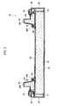
Fig. 3 is a cross-sectional view of a second freezing compartment door of the first embodiment. - [
Fig. 4 ]
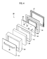
Fig. 4 is an exploded perspective view of the second freezing compartment door. - [
Fig. 5 ]
Fig. 5 is an enlarged cross-sectional view of the second freezing compartment door. - [
Fig. 6 ]
Fig. 6 includes cross-sectional views of a plurality of examples concerning the structure of an elastic portion. - [
Fig. 7 ]
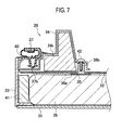
Fig. 7 is an enlarged cross-sectional view illustrating a modification of the second freezing compartment door of the first embodiment. - [
Fig. 8 ]
Fig. 8 is an enlarged cross-sectional view of a second freezing compartment door of the second embodiment. - [
Fig. 9 ]
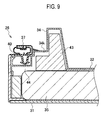
Fig. 9 is an enlarged cross-sectional view of a second freezing compartment door of the third embodiment. - [
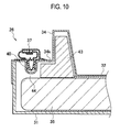
Fig. 10 ]
Fig. 10 is an enlarged cross-sectional view of a second freezing compartment door of the fourth embodiment. - [
Fig. 11 ]
Fig. 11 is an enlarged cross-sectional view illustrating a modification of the second freezing compartment door of the fourth embodiment. - [
Fig. 12 ]
Fig. 12 is an enlarged cross-sectional view of a second freezing compartment door of the fifth embodiment. - Hereinafter, a description is given of embodiments in detail with reference to the drawings.
- As illustrated in
Figs. 1 and2 , a refrigerator 1 of a first embodiment includes an insulating box body 3 andplural doors 21 to 26. The insulating box body 3 is opened at the front, and the inside thereof is partitioned into plural compartments. Theplural doors 21 to 26 seal front openings of the respective compartments. For convenience of the following description, the side where thedoors 21 to 26 are provided are referred to as a front side, and the side where the insulating box body 3 is located is referred to as a back side (seeFig. 1 ). - The insulating box body 3 includes an inner box, an outer box, and
vacuum insulating materials 35 sandwiched between the inner and outer boxes as an insulating material. Thevacuum insulating materials 35 are sandwiched between the substantially entire opposing surfaces of the outer and inner boxes. InFig. 2 , only thevacuum insulating material 35 of the right-side plate of the refrigerator 1, which is located to the observer's right, is indicated by a dotted line for explanation, but actually, thevacuum insulating material 35 is provided for each of the top, bottom, left-side, and back plates. - The insulating box body 3 is partitioned into five compartments, for example. The five compartments are used as a refrigerating
compartment 11, avegetable compartment 12, anice compartment 13 and afirst freezing compartment 14, that are arranged side by side, and asecond freezing compartment 15, which are sequentially arranged from above, for example. On the front opening of the refrigeratingcompartment 11, double door-type refrigerating compartment first andsecond doors vegetable compartment 12,ice compartment 13,first freezing compartment 14, andsecond freezing compartment 15, avegetable compartment door 23, anice compartment door 24, a firstfreezing compartment door 25, and a secondfreezing compartment door 26, which are drawer-type, are attached, respectively. - The doors of the refrigerator 1 also include the
vacuum insulating materials 35. Each of thevacuum insulating materials 35 is formed in such a manner that an inorganic core material, such as grass wool, is vacuum-packed with a laminate film of aluminum foil and synthetic resin or an aluminum-deposited laminate film of synthetic resin. The vacuum insulating materials formed by the aforementioned manufacturing method are difficult to form into strictly fixed thickness because of the manufacturing difficulties and cause individual differences in thickness of products. However, the doors of the refrigerator 1 need to be surely closed air-tightly, and the distance between the outer plate and a gasket fitting member needs to be always fixed. Accordingly, in order to manufacture doors of a same size using a vacuum insulating material whose thickness varies from product to product, there is a demand for a structure capable of accommodating the varying thickness of the vacuum insulating material. Hereinafter, a description is given of a door structure capable of accommodating varying thickness of a vacuum insulating material. - For explanation of the door structure, the second freezing
compartment door 26 is described as a representative door. As illustrated inFigs. 3 to 5 , the second freezingcompartment door 26 includes anouter plate 31, aninner plate 32, aside frame 33, agasket fitting member 40, athroat member 34, thevacuum insulating material 35,fasteners 36, agasket 37, and ahandle 39. In the second freezingcompartment door 26, thethroat member 34 is joined to the inside of the frame of thegasket fitting member 40 to be integrally formed with the same. - The
outer plate 31 of the second freezingcompartment door 26 is fixed near the front end of theside frame 33. Thegasket fitting member 40 andthroat member 34 are fixed near the back end of theside frame 33. Moreover, theinner plate 32 of the second freezingcompartment door 26 is provided on the front side of thethroat member 34. Thevacuum insulating material 35 is provided between theouter plate 31 and theinner plate 32. Thevacuum insulating material 35 has such an area (size) that occupies the substantially entire opposing surfaces of theouter plate 31 and theinner plate 32. Thegasket 37 is fitted to the back side of thegasket fitting member 40. Thehandle 39 is attached to the front surface of theouter plate 31. - A
soft tape 41 is wound around the circumference of thevacuum insulating material 35. Thesoft tape 41 is made of a material having a heat insulating effect such as sponge tape. The front surface of thevacuum insulating material 35 is fixed to theouter plate 31 by bonding or the like. On the back surface of thevacuum insulating material 35, theplural fasteners 36 are fixed by bonding or the like. - As illustrated in
Fig. 5 , eachfastener 36 includes abase plate 36a formed into a plate and acylindrical portion 36b extending backward from the center of thebase plate 36a. Thecylindrical portion 36b includes a threaded hole, in which a later-describedscrew 42 is screwed. Thebase plate 36a is fixed to thevacuum insulating material 35 by bonding. Thecylindrical portion 36b penetrates theinner plate 32 and abuts on the edge portion of thethroat member 34. Thescrew 42 fixes the edge portion of thethroat member 34 to thecylindrical portion 36b. When thethroat member 34 is fixed to thefastener 36, there is a separatingspace 44 formed between thevacuum insulating material 35 and the front end of thegasket fitting member 40 integrally formed with thethroat member 34. - Specifically, the
throat member 34,cylindrical portion 36b, andinner plate 32 are provided to satisfy: b-c > a where a is a distance between the portion of thethroat member 34 abutting on thefastener 36 and the front end of thegasket fitting member 40; b is a height of thecylindrical portion 36b of thefastener 36; and c is the thickness of theinner plate 32. - The space within the
throat member 34 is previously filled with an insulatingmaterial 43 such as polystyrene foam. At least one place near the insulatingmaterial 43 in thethroat member 34, anelastic portion 34k is formed. As illustrated inFig. 6 (a) , theelastic portion 34k is formed into a thin circular shape and is more deformable than the other part around the same. When thevacuum insulating material 35 is thicker or thinner than designed, thefastener 36 is displaced a little forward or backward, and the fixing position of the edge portion of the throat member 34 (afastener fixing portion 34b) moves forward or backward. Even in such a case, because of provision of theelastic portion 34k, theelastic portion 34k can deform to move the edge portion of thethroat member 34. In the drawings ofFigs. 6(a) to (c) , reference symbols A show examples of deformation of the edge portion of thethroat member 34 when thevacuum insulating material 35 is thick, and reference symbols B show examples of deformation of the edge portion of thethroat member 34 when thevacuum insulating material 35 is thin. - Specifically, the deformation (displacement) caused at the edge portion of the
throat member 34 is absorbed by theelastic portion 34k and is not transmitted to thegasket fitting member 40. Accordingly, the distance between theouter plate 32 andgasket fitting member 40 is kept fixed. In the second freezingcompartment door 26 of the first embodiment, theelastic portion 34k of thethroat member 34 can accommodate varying thickness of thevacuum insulating material 35. It is therefore possible to manufacture a door with fixed thickness even by using a vacuum insulating material, whose thickness is more likely to vary from product to product. - The shape of the
elastic portion 34k is not limited to the thin circular recess illustrated inFig. 6(a) . For example, theelastic portion 34k may be formed into a V-shaped recess as illustrated inFig. 6(b) or may include plural recesses as illustrated inFig. 6(c) . Theelastic portion 34k may be made of a material deformable more easily than the other part of the throat member. - Hereinafter, the structure of the second freezing
compartment door 26 is described in more detail. As illustrated inFigs. 3 to 5 , theouter plate 31 is a rectangular plate and is fixed to theside frame 33 by bonding or the like. Theinner plate 32 is a rectangular plate and includes plural through-holes 32a through which thefasteners 36 penetrate. - The
side frame 33 is a rectangular frame to which theouter plate 31 andgasket fitting member 40 are fixed. Theside frame 33 includes: asidewall 33a forming the side surface of the second freezingcompartment door 26; an outerplate attachment portion 33b which is formed near the front end of thesidewall 33a in such a manner as to protrude into the frame; and a fixingportion 33c that is formed near the back end of thesidewall 33a, to which thegasket fitting member 40 is fixed. The fixingportion 33c includes: afront protrusion portion 33d that abuts on a front corner of thegasket fitting member 40; and aback protrusion portion 33e that holds and sandwiches thegasket fitting member 40 in cooperation with thefront protrusion portion 33d. The front andback protrusion portions sidewall 33a toward the inside of the frame and extend along thesidewall 33a. - The
gasket fitting member 40 is a frame joined to the outside of thethroat member 34. Thegasket fitting member 40 is formed into a hollow box having an opening into which a later-describedinsertion portion 37b of thegasket 37 is inserted. At the back corner of thegasket fitting member 40, astep portion 40a is formed. Thestep portion 40a is engaged with theback protrusion portion 33e of theside frame 33. - When the second freezing
compartment door 26 is closed, thethroat member 34 enters the inside of the insulating box body 3 to be laid on the inner surface of the insulating box body 3. Thethroat member 34 thereby prevents leakage of cold air within the insulating box body 3. Thethroat member 34 has a rectangular frame shape and is integrally formed with thegasket fitting member 40 so that thegasket fitting member 40 is joined to the circumference of thethroat member 34. - The
throat member 34 includes: a protrudingportion 34a protruding backward (toward the inside of the insulating box body 3); and thefastener fixing portion 34b located to the inside of the frame of the protrudingportion 34a. The protrudingportion 34a is hollow, and the space within the protrudingportion 34a is filled with the insulatingmaterial 43 such as styrene foam. The aforementionedelastic portion 34k is formed at a proper place in the back end face (back surface) of the protrudingportion 34a. Thefastener fixing portion 34b includes plural threaded holes through which thescrews 42 penetrate. - The
gasket 37 is a frame including a hollow sealedair cushion portion 37a and includes theinsertion portion 37b, which has an arrowhead shape. Thegasket 37 further includes amagnet 37c to the back side of theair cushion portion 37a. Themagnet 37c is configured to be magnetically attached to the peripheral surface of the opening of the insulating box body 3. Thegasket 37 is made of a flexible material, and by using the flexibility thegasket 37, theinsertion portion 37b is pressed into thegasket fitting member 40 to be attached to thegasket fitting member 40. - The
outer plate 31 of the second freezingcompartment door 26 is fixed to the outerplate attachment portion 33b of theside frame 33, and thegasket fitting member 40 integrally formed with thethroat member 34 is fitted to the fixingportion 33c of theside frame 33. In other words, the thickness of the second freezingcompartment door 26, which is the distance between theouter plate 31 and the back surface of thegasket fitting member 40, is fixed. In the second freezingcompartment door 26, thevacuum insulating material 35 is provided on the back side of theouter plate 31, and to the back side of thevacuum insulating material 35, theinner plate 32 is provided with thefasteners 36 interposed therebetween. Theinner plate 32 is bonded to the back surface of thevacuum insulating material 35. To the back side of theinner plate 32, thegasket fitting member 40 andthroat member 34 are located with the separatingspace 44 interposed therebetween. Thefastener fixing portion 34b of thethroat member 34 is fixed to thefasteners 36 with thescrews 42. - According to the first embodiment, the
elastic portion 34k is provided in thethroat member 34 as described above. Accordingly, even when the position of any of thefasteners 36 is moved up or down according to the thickness of thevacuum insulating material 35, theelastic portion 34k deforms as indicated by A or B inFig. 6 to move thefastener fixing portion 34b forward or backward and can thereby absorb the displacement of thefastener 36. This can facilitate manufacturing the second freezingcompartment door 26 with the thickness always fixed. - Moreover, the
gasket fitting member 40 is integrally formed with thethroat member 34. It is therefore possible to reduce the number of steps for assembling the door and reduce the manufacturing cost. - The method of fixing the
fasteners 36 and thevacuum insulating material 35 is not limited to bonding and may include using a hook-and-loop fastener or the like. The second freezingcompartment door 26 is described as the representative door of the refrigerator 1, but the same configuration is applicable to the other doors. - Moreover, the
elastic portion 34k is provided in the back end face of thethroat member 34 in the above-described embodiment. However, theelastic portion 34k may be provided in the face connecting thegasket fitting member 40 and thethroat member 34 as illustrated inFig. 7 . The thickness of thevacuum insulating material 35 varying from product to product can be absorbed by the forward or backward displacement of thewhole throat member 34 without a change of the position of thegasket fitting member 40. - Next, a description is given of a second embodiment relating to the structure of the doors of the refrigerator 1. As illustrated in
Fig. 8 , in the second freezingcompartment door 26 in the second embodiment, thegasket fitting member 40 is directly fixed to theouter plate 31. In the following description, the same members as those of the first embodiment are indicated by the same reference numerals. - The second freezing
compartment door 26 includes theouter plate 31 formed into a flat box; theinner plate 32 formed into a plate; thevacuum insulating material 35 sandwiched between theouter plate 31 and theinner plate 32; thegasket fitting member 40; thethroat member 34; thefasteners 36; and thegasket 37. Herein, thegasket fitting member 40 andthroat member 34 are integrally formed. - The
outer plate 31 includes a fitting hole (a fitting recess, a fitting groove) 31a in the sidewall. In thefitting hole 31a, a later-describedpawl 40c of thegasket fitting member 40 is fitted. Thegasket fitting member 40 includes asidewall 40b at the outer end, thesidewall 40b extending forward. Thepawl 40c is formed in the vicinity of the front end of thesidewall 40b. Furthermore, thethroat member 34 includes theelastic portion 34k in a similar manner to the first embodiment. The space within thethroat member 34 is filled with the insulatingmaterial 43. - In the second freezing
compartment door 26, thevacuum insulating material 35 is bonded to the back surface of theouter plate 31, and theinner plate 32 is provided on the back side of thevacuum insulating material 35 with thefasteners 36 interposed-therebetween. Thegasket fitting member 40 andthroat member 34 are provided with the separatingspace 44 formed to the back side of theinner plate 32. Moreover, thepawl 40c is fitted into thefitting hole 31a of theouter plate 31 to fix thegasket fitting member 40 to theouter plate 31. Thegasket fitting member 40 is fitted on theouter plate 31 in such a manner, so that the distance between thegasket fitting member 40 and theouter plate 31, that is, the thickness of the second freezingcompartment door 26 is always fixed. The other configuration is the same as that of the first embodiment, and the detailed description thereof is omitted. - In the second freezing
compartment door 26 of the second embodiment, similarly to the first embodiment, the separatingspace 44 is formed between thevacuum insulating material 35 and the front end of thegasket fitting member 40. Accordingly, the second freezingcompartment door 26 with the thickness fixed can be easily manufactured even when the thickness of thevacuum insulating material 35 varies because of individual differences of products. - Next, a description is given of a third embodiment relating to the structure of the doors of the refrigerator 1. As illustrated in
Fig. 9 , in the second freezingcompartment door 26 of the third embodiment, thegasket fitting member 40,throat member 34, and theinner plate 32 are integrally formed. To be specific, the second freezingcompartment door 26 includes: theouter plate 31; theinner plate 32,gasket fitting member 40, andthroat member 34, which are integrally formed; thevacuum insulating material 35 sandwiched between theouter plate 31 and theinner plate 32; theside frame 33; and thegasket 37. - The
outer plate 31 is fixed to the front end of theside frame 33, and thegasket fitting member 40 is fixed near the back end of theside frame 33. Theelastic portion 34k is formed in the joint face of thegasket fitting member 40 andthroat member 34. The front surface of thevacuum insulating material 35 is bonded to theouter plate 31, and the back surface thereof is bonded to theinner plate 32. The separatingspace 44 is formed between thevacuum insulating material 35 and the front end of thegasket fitting member 40. - In the second freezing
compartment door 26 of the third embodiment, theinner plate 32 is pressed backward when thevacuum insulating material 35 is thick. However, theelastic portion 34k between thegasket fitting member 40 andthroat member 34 deforms to absorb the change in thickness, and thegasket fitting member 40 is not displaced even when theinner plate 32 andthroat member 34 are pressed backward. It is therefore possible to easily manufacture a door which has fixed distance between theouter plate 31 andgasket fitting member 40 and employs thevacuum insulating material 35 whose thickness varies from product to product. - In the case of the third embodiment, the
inner plate 32,gasket fitting member 40, andthroat member 34 are integrally formed, thus facilitating assembly of the door and reducing the manufacturing cost. - Next, a description is given of the fourth embodiment relating to the structure of the doors of the refrigerator 1. As illustrated in
Fig. 10 , the second freezingcompartment door 26 of the fourth embodiment includes theinner plate 32,gasket fitting member 40, andthroat member 34 which are integrally formed in a similar manner to the third embodiment. Moreover, theouter plate 31 is formed into a flat box and is directly fitted into thegasket fitting member 40. - Also in the second freezing
compartment door 26 of the fourth embodiment, the separatingspace 44 is formed between thevacuum insulating material 35 and the front end of thegasket fitting member 40. Moreover, theelastic portion 34k is formed between thegasket fitting member 40 andthroat member 34. The front surface of thevacuum insulating material 35 is bonded to theouter plate 31, and the back surface thereof is bonded to theinner plate 32. - Also in the fourth embodiment, it is possible to easily manufacture a door which has fixed distance between the
outer plate 31 andgasket fitting member 40, that is, fixed door thickness and employs thevacuum insulating material 35, whose thickness varies from product to product. - As illustrated in
Fig. 11 , thegasket fitting member 40 may be fixed to theouter plate 31 with ascrew 46 or the like. Alternatively, thegasket fitting member 40 may be joined to theouter plate 31 by a fitting means such as a pawl. In any of the above cases, the same effect as described above can be obtained by providing the separatingspace 44 andelastic portion 34k. - Next, a description is given of a fifth embodiment relating to the structure of the doors of the refrigerator 1. As illustrated in
Fig. 12 , the second freezingcompartment door 26 of the fifth embodiment, theinner plate 32 andthroat member 34 are integrally formed. In other words, the second freezingcompartment door 26 of the fifth embodiment includes theouter plate 31, theinner plate 32 integrally formed with thethroat member 34, thegasket fitting member 40, thevacuum insulating material 35 sandwiched between theouter plate 31 and theinner plate 32, and thegasket 37. - The
outer plate 31 is formed into a flat box. Thegasket fitting member 40 is a rectangular frame including a sidewall 40d fitted on the circumference of theouter plate 31. Thegasket fitting member 40 is fitted on the back end of theouter plate 31 and is joined by bonding or the like. Thegasket fitting member 40 may be joined to theouter plate 31 using thescrew 46 shown inFig. 11 . - In the second freezing
compartment door 26, thevacuum insulating material 35 is bonded to the back surface of theouter plate 31, and theinner plate 32 is bonded to the back surface of thevacuum insulating material 35. Thethroat member 34 integrally formed with theinner plate 32 is located with a space from thegasket fitting member 40 and is joined to thegasket fitting member 40 with ascrew 48, to which anelastic body 49 is attached. Theelastic body 49 is configured to accommodate the variations in distance between the end of thethroat member 34 and thegasket fitting member 40. In a similar manner to the first to fourth embodiments, the separatingspace 44 is formed between the front end of thegasket fitting member 40 and thevacuum insulating material 35. - Even with the thus-configured second freezing
compartment door 26 or even when thevacuum insulating material 35 whose thickness varies from product to product is used as the insulating material, it is possible to manufacture a door having a fixed thickness by accommodating the varying thickness of thevacuum insulating material 35. - Some of the embodiments of the present invention are described above but are presented by way of example. The embodiments are not intended to limit the scope of the invention. These novel embodiments can be carried out in other various modes and can be variously omitted, replaced, and changed without departing from the gist of the invention. The embodiments and modifications thereof are included in the scope and gist of the invention and also included in the invention described in claims and equivalents thereof.
Claims (8)
- A refrigerator, comprising:an insulating box body in which a space between an inner box and an outer box is filled with an insulating material and an opening is provided at the front; anda door configured to close the opening at the front of the insulating box body, whereinthe door includes:an outer plate;an inner plate opposed to the outer plate;a vacuum insulating material sandwiched between the outer plate and the inner plate;a gasket attached to an entire circumference of the door in the vicinity of an edge on an inner side of the door;a frame-shaped gasket fitting member to which the gasket is fitted; anda frame-shaped throat member configured to enter an inside of the insulating box body to prevent cold air from flowing out when the door is closed, andthe distance between the outer plate and the gasket fitting member is fixed, anda separating space is formed between a front end of the gasket fitting member and a back surface of the vacuum insulating material.
- The refrigerator according to claim 1, wherein the throat member and the gasket fitting member are integrally formed.
- The refrigerator according to claim 1 or 2, wherein
the throat member and gasket fitting member are provided on the back side of the inner plate, and
a protrusion at a top of an attachment portion with a base portion fixed to the back surface of the vacuum insulating material is penetrated through the inner plate and is connected to an edge portion of the throat member. - The refrigerator according to any one of claims 1 to 3, wherein
an easily deformable elastic portion is provided between the throat member and gasket fitting member or in the throat member. - The refrigerator according to any one of claims 1 to 4, wherein
the throat member is filled with an insulator, and
the insulator is spaced from the back-surface of the vacuum insulating material. - The refrigerator according to any one of claims 1 to 5, wherein
the throat member and the inner plate are movable relative to the gasket fitting member. - The refrigerator according to claim 1, wherein
the throat member and the inner plate are integrally formed, and the gasket fitting member is separated from the throat member, and an edge portion of the throat member is connected to an edge portion of the gasket fitting member with an elastic body. - The refrigerator according to claim 1, wherein
the gasket fitting member, the throat member, and the inner plate are integrally formed, and an elastic portion easily deformable is formed between the gasket fitting member and the throat member or in the throat member.
Applications Claiming Priority (2)
| Application Number | Priority Date | Filing Date | Title |
|---|---|---|---|
| JP2012063803A JP6081069B2 (en) | 2012-03-21 | 2012-03-21 | refrigerator |
| PCT/JP2012/078960 WO2013140658A1 (en) | 2012-03-21 | 2012-11-08 | Refrigerator |
Publications (2)
| Publication Number | Publication Date |
|---|---|
| EP2829827A1 true EP2829827A1 (en) | 2015-01-28 |
| EP2829827A4 EP2829827A4 (en) | 2015-11-18 |
Family
ID=49222146
Family Applications (1)
| Application Number | Title | Priority Date | Filing Date |
|---|---|---|---|
| EP12872109.9A Withdrawn EP2829827A4 (en) | 2012-03-21 | 2012-11-08 | FRIDGE |
Country Status (5)
| Country | Link |
|---|---|
| EP (1) | EP2829827A4 (en) |
| JP (1) | JP6081069B2 (en) |
| CN (1) | CN104254749B (en) |
| TW (1) | TWI519750B (en) |
| WO (1) | WO2013140658A1 (en) |
Cited By (19)
| Publication number | Priority date | Publication date | Assignee | Title |
|---|---|---|---|---|
| EP2985551A1 (en) * | 2014-08-15 | 2016-02-17 | Anthony International | Thermal insulated frame for a refrigerated enclosure |
| WO2017023094A1 (en) * | 2015-08-03 | 2017-02-09 | Lg Electronics Inc. | Vacuum adiabatic body and refrigerator |
| WO2017023095A1 (en) * | 2015-08-03 | 2017-02-09 | Lg Electronics Inc. | Vacuum adiabatic body and refrigerator |
| WO2017023100A1 (en) | 2015-08-03 | 2017-02-09 | Lg Electronics Inc. | Vacuum adiabatic body and refrigerator |
| WO2017023097A1 (en) * | 2015-08-03 | 2017-02-09 | Lg Electronics Inc. | Vacuum adiabatic body and refrigerator |
| EP3569757A1 (en) * | 2018-05-16 | 2019-11-20 | BSH Hausgeräte GmbH | Sealing element having a closure element in the form of a ring section, door with a sealing element and a household appliance |
| US10753671B2 (en) | 2015-08-03 | 2020-08-25 | Lg Electronics Inc. | Vacuum adiabatic body and refrigerator |
| US10760849B2 (en) | 2015-08-03 | 2020-09-01 | Lg Electronics Inc. | Vacuum adiabatic body and refrigerator |
| US10788257B2 (en) | 2015-08-04 | 2020-09-29 | Lg Electronics Inc. | Vaccum adiabatic body and refrigerator |
| US10816129B2 (en) | 2015-08-03 | 2020-10-27 | Lg Electronics Inc. | Vacuum adiabatic body and refrigerator |
| US10837696B2 (en) | 2015-08-03 | 2020-11-17 | Lg Electronics Inc. | Vacuum adiabatic body and refrigerator |
| US10876786B2 (en) | 2015-08-03 | 2020-12-29 | Lg Electronics Inc. | Vacuum adiabatic body, fabrication method for the vacuum adiabatic body, porous substance package, and refrigerator |
| US10883758B2 (en) | 2015-08-03 | 2021-01-05 | Lg Electronics Inc. | Vacuum adiabatic body and refrigerator |
| US10928119B2 (en) | 2015-08-03 | 2021-02-23 | Lg Electronics Inc. | Vacuum adiabatic body and refrigerator |
| US10941974B2 (en) | 2015-08-03 | 2021-03-09 | Lg Electronics Inc. | Vacuum adiabatic body and refrigerator |
| US11274785B2 (en) | 2015-08-03 | 2022-03-15 | Lg Electronics Inc. | Vacuum adiabatic body and refrigerator |
| WO2022092963A1 (en) * | 2020-11-02 | 2022-05-05 | Lg Electronics Inc. | Vacuum adiabatic body |
| US11692764B2 (en) | 2018-06-27 | 2023-07-04 | Lg Electronics Inc. | Vacuum adiabatic body and refrigerator |
| US12259178B2 (en) | 2020-11-02 | 2025-03-25 | Lg Electronics Inc. | Vacuum adiabatic body |
Families Citing this family (42)
| Publication number | Priority date | Publication date | Assignee | Title |
|---|---|---|---|---|
| US9221210B2 (en) | 2012-04-11 | 2015-12-29 | Whirlpool Corporation | Method to create vacuum insulated cabinets for refrigerators |
| US9140481B2 (en) | 2012-04-02 | 2015-09-22 | Whirlpool Corporation | Folded vacuum insulated structure |
| JP6105242B2 (en) * | 2012-09-25 | 2017-03-29 | 東芝ライフスタイル株式会社 | refrigerator |
| US9689604B2 (en) | 2014-02-24 | 2017-06-27 | Whirlpool Corporation | Multi-section core vacuum insulation panels with hybrid barrier film envelope |
| US10052819B2 (en) | 2014-02-24 | 2018-08-21 | Whirlpool Corporation | Vacuum packaged 3D vacuum insulated door structure and method therefor using a tooling fixture |
| US9599392B2 (en) | 2014-02-24 | 2017-03-21 | Whirlpool Corporation | Folding approach to create a 3D vacuum insulated door from 2D flat vacuum insulation panels |
| DE102014214102A1 (en) * | 2014-07-21 | 2016-01-21 | BSH Hausgeräte GmbH | Wall for a household refrigerating appliance, household refrigerating appliances and method for producing a wall |
| US9476633B2 (en) | 2015-03-02 | 2016-10-25 | Whirlpool Corporation | 3D vacuum panel and a folding approach to create the 3D vacuum panel from a 2D vacuum panel of non-uniform thickness |
| US10161669B2 (en) | 2015-03-05 | 2018-12-25 | Whirlpool Corporation | Attachment arrangement for vacuum insulated door |
| US9897370B2 (en) | 2015-03-11 | 2018-02-20 | Whirlpool Corporation | Self-contained pantry box system for insertion into an appliance |
| US9441779B1 (en) | 2015-07-01 | 2016-09-13 | Whirlpool Corporation | Split hybrid insulation structure for an appliance |
| KR102514039B1 (en) * | 2015-08-03 | 2023-03-24 | 엘지전자 주식회사 | Vacuum adiabatic body and refrigerator |
| US10041724B2 (en) | 2015-12-08 | 2018-08-07 | Whirlpool Corporation | Methods for dispensing and compacting insulation materials into a vacuum sealed structure |
| US11052579B2 (en) | 2015-12-08 | 2021-07-06 | Whirlpool Corporation | Method for preparing a densified insulation material for use in appliance insulated structure |
| US12508751B2 (en) | 2015-12-08 | 2025-12-30 | Whirlpool Corporation | Insulation compaction device and method for forming an insulated structure for an appliance |
| US10222116B2 (en) | 2015-12-08 | 2019-03-05 | Whirlpool Corporation | Method and apparatus for forming a vacuum insulated structure for an appliance having a pressing mechanism incorporated within an insulation delivery system |
| US10429125B2 (en) | 2015-12-08 | 2019-10-01 | Whirlpool Corporation | Insulation structure for an appliance having a uniformly mixed multi-component insulation material, and a method for even distribution of material combinations therein |
| US10422573B2 (en) | 2015-12-08 | 2019-09-24 | Whirlpool Corporation | Insulation structure for an appliance having a uniformly mixed multi-component insulation material, and a method for even distribution of material combinations therein |
| US10422569B2 (en) | 2015-12-21 | 2019-09-24 | Whirlpool Corporation | Vacuum insulated door construction |
| US9752818B2 (en) | 2015-12-22 | 2017-09-05 | Whirlpool Corporation | Umbilical for pass through in vacuum insulated refrigerator structures |
| US9840042B2 (en) | 2015-12-22 | 2017-12-12 | Whirlpool Corporation | Adhesively secured vacuum insulated panels for refrigerators |
| US10018406B2 (en) | 2015-12-28 | 2018-07-10 | Whirlpool Corporation | Multi-layer gas barrier materials for vacuum insulated structure |
| US10610985B2 (en) | 2015-12-28 | 2020-04-07 | Whirlpool Corporation | Multilayer barrier materials with PVD or plasma coating for vacuum insulated structure |
| US10807298B2 (en) | 2015-12-29 | 2020-10-20 | Whirlpool Corporation | Molded gas barrier parts for vacuum insulated structure |
| US10030905B2 (en) | 2015-12-29 | 2018-07-24 | Whirlpool Corporation | Method of fabricating a vacuum insulated appliance structure |
| US11247369B2 (en) | 2015-12-30 | 2022-02-15 | Whirlpool Corporation | Method of fabricating 3D vacuum insulated refrigerator structure having core material |
| EP3443284B1 (en) | 2016-04-15 | 2020-11-18 | Whirlpool Corporation | Vacuum insulated refrigerator structure with three dimensional characteristics |
| US10712080B2 (en) | 2016-04-15 | 2020-07-14 | Whirlpool Corporation | Vacuum insulated refrigerator cabinet |
| US11320193B2 (en) | 2016-07-26 | 2022-05-03 | Whirlpool Corporation | Vacuum insulated structure trim breaker |
| WO2018034665A1 (en) | 2016-08-18 | 2018-02-22 | Whirlpool Corporation | Machine compartment for a vacuum insulated structure |
| JP6854106B2 (en) * | 2016-10-13 | 2021-04-07 | 東芝ライフスタイル株式会社 | refrigerator |
| WO2018101954A1 (en) | 2016-12-02 | 2018-06-07 | Whirlpool Corporation | Hinge support assembly |
| KR102902150B1 (en) * | 2017-01-03 | 2025-12-19 | 삼성전자주식회사 | Refrigerator |
| JP6517858B2 (en) * | 2017-02-27 | 2019-05-22 | 東芝ライフスタイル株式会社 | refrigerator |
| WO2019208457A1 (en) * | 2018-04-26 | 2019-10-31 | パナソニックIpマネジメント株式会社 | Refrigerator |
| CN108981274A (en) * | 2018-05-31 | 2018-12-11 | 东芝家用电器制造(南海)有限公司 | Refrigerator |
| US10907888B2 (en) | 2018-06-25 | 2021-02-02 | Whirlpool Corporation | Hybrid pigmented hot stitched color liner system |
| US10907891B2 (en) | 2019-02-18 | 2021-02-02 | Whirlpool Corporation | Trim breaker for a structural cabinet that incorporates a structural glass contact surface |
| JP6854314B2 (en) * | 2019-04-12 | 2021-04-07 | 東芝ライフスタイル株式会社 | refrigerator |
| KR102896121B1 (en) * | 2019-07-09 | 2025-12-05 | 엘지전자 주식회사 | Vacuum adiabatic body and refrigerator |
| JP7499014B2 (en) * | 2019-10-08 | 2024-06-13 | 日立グローバルライフソリューションズ株式会社 | Insulated refrigerator door and refrigerator |
| JP2024061275A (en) * | 2022-10-21 | 2024-05-07 | 東芝ライフスタイル株式会社 | Refrigerator door and refrigerator |
Family Cites Families (26)
| Publication number | Priority date | Publication date | Assignee | Title |
|---|---|---|---|---|
| GB729393A (en) * | 1952-07-09 | 1955-05-04 | Gen Electric | Improvements in and relating to insulated door structures |
| JPS5750688U (en) * | 1980-09-10 | 1982-03-23 | ||
| JPS5911291U (en) * | 1982-07-14 | 1984-01-24 | 松下冷機株式会社 | insulation wall |
| JPS5966679A (en) * | 1982-10-06 | 1984-04-16 | 株式会社日立製作所 | Door of refrigerator |
| JPS6055976U (en) * | 1983-09-26 | 1985-04-19 | 株式会社東芝 | refrigerator insulated door |
| IT8434032U1 (en) * | 1984-05-24 | 1985-11-24 | Zanussi Elettrodomestici | Refrigerator door |
| JPS60191889U (en) * | 1984-05-29 | 1985-12-19 | 株式会社東芝 | insulation door |
| JPS613387U (en) * | 1984-06-12 | 1986-01-10 | 三菱電機株式会社 | refrigerator |
| JPS613389U (en) * | 1984-06-12 | 1986-01-10 | 松下冷機株式会社 | refrigerator door |
| JPH07234067A (en) * | 1994-02-21 | 1995-09-05 | Hitachi Ltd | Vacuum insulation doors for refrigerators, etc. |
| JPH0814485A (en) * | 1994-06-29 | 1996-01-16 | Sanyo Electric Co Ltd | Heat insulating body structure |
| KR0186124B1 (en) * | 1995-12-29 | 1999-04-15 | 이종수 | Insulation Case of Vending Machine |
| JP3547914B2 (en) * | 1996-09-24 | 2004-07-28 | 三菱電機株式会社 | Gaskets for refrigerators and refrigerators |
| TR199700083A2 (en) * | 1997-02-03 | 1998-08-21 | Ar�El�K A.�. | Refrigerator door with high insulation and recycling performance. |
| JP3872161B2 (en) * | 1997-04-18 | 2007-01-24 | 松下冷機株式会社 | Refrigerator door |
| JP3546345B2 (en) * | 1997-12-05 | 2004-07-28 | 三菱電機株式会社 | Freezer refrigerator |
| JPH11353544A (en) * | 1998-06-04 | 1999-12-24 | Sanden Corp | Assembling structure for heat insulation casing |
| JP2001091147A (en) * | 1999-09-27 | 2001-04-06 | Matsushita Refrig Co Ltd | Heat insulation door and storage chamber equipped therewith |
| JP2004116695A (en) * | 2002-09-27 | 2004-04-15 | Nisshinbo Ind Inc | Vacuum insulation board and heat insulation container using the vacuum insulation board |
| JP3862170B2 (en) * | 2003-01-30 | 2006-12-27 | 富士電機リテイルシステムズ株式会社 | Insulation board and vending machine |
| JP2005275642A (en) * | 2004-03-24 | 2005-10-06 | Fuji Electric Retail Systems Co Ltd | Heat insulating panel for vending machine and vending machine |
| JP4198103B2 (en) | 2004-09-24 | 2008-12-17 | 三洋電機株式会社 | Refrigerator door device |
| JP5098149B2 (en) * | 2005-10-27 | 2012-12-12 | パナソニック株式会社 | vending machine |
| JP5303397B2 (en) * | 2009-08-12 | 2013-10-02 | 日立アプライアンス株式会社 | refrigerator |
| JP5193980B2 (en) * | 2009-09-28 | 2013-05-08 | 日立アプライアンス株式会社 | refrigerator |
| JP5513855B2 (en) * | 2009-11-11 | 2014-06-04 | 株式会社東芝 | refrigerator |
-
2012
- 2012-03-21 JP JP2012063803A patent/JP6081069B2/en not_active Expired - Fee Related
- 2012-11-08 CN CN201280071589.3A patent/CN104254749B/en not_active Expired - Fee Related
- 2012-11-08 WO PCT/JP2012/078960 patent/WO2013140658A1/en not_active Ceased
- 2012-11-08 EP EP12872109.9A patent/EP2829827A4/en not_active Withdrawn
- 2012-11-14 TW TW101142436A patent/TWI519750B/en not_active IP Right Cessation
Cited By (58)
| Publication number | Priority date | Publication date | Assignee | Title |
|---|---|---|---|---|
| EP2985551A1 (en) * | 2014-08-15 | 2016-02-17 | Anthony International | Thermal insulated frame for a refrigerated enclosure |
| US9389013B2 (en) | 2014-08-15 | 2016-07-12 | Anthony International | Thermal frame for a refrigerated enclosure |
| US12078409B2 (en) | 2015-08-03 | 2024-09-03 | Lg Electronics Inc. | Vacuum adiabatic body and refrigerator |
| US12320464B2 (en) | 2015-08-03 | 2025-06-03 | Lg Electronics Inc. | Vacuum adiabatic body and refrigerator |
| WO2017023100A1 (en) | 2015-08-03 | 2017-02-09 | Lg Electronics Inc. | Vacuum adiabatic body and refrigerator |
| WO2017023097A1 (en) * | 2015-08-03 | 2017-02-09 | Lg Electronics Inc. | Vacuum adiabatic body and refrigerator |
| KR20170016241A (en) * | 2015-08-03 | 2017-02-13 | 엘지전자 주식회사 | Vacuum adiabatic body and refrigerator |
| KR20170016187A (en) * | 2015-08-03 | 2017-02-13 | 엘지전자 주식회사 | Vacuum adiabatic body and refrigerator |
| EP3332196A4 (en) * | 2015-08-03 | 2019-03-27 | LG Electronics Inc. | VACUUM ADIABATIC BODY AND REFRIGERATOR |
| RU2684737C1 (en) * | 2015-08-03 | 2019-04-12 | ЭлДжи ЭЛЕКТРОНИКС ИНК. | Vacuum adiabatic element and refrigerator |
| AU2016303870B2 (en) * | 2015-08-03 | 2019-06-27 | Lg Electronics Inc. | Vacuum adiabatic body and refrigerator |
| EP4660562A3 (en) * | 2015-08-03 | 2026-02-18 | LG Electronics Inc. | Vacuum adiabatic body and refrigerator |
| US10584914B2 (en) | 2015-08-03 | 2020-03-10 | Lg Electronics Inc. | Vacuum adiabatic body and refrigerator |
| US10753671B2 (en) | 2015-08-03 | 2020-08-25 | Lg Electronics Inc. | Vacuum adiabatic body and refrigerator |
| US10760849B2 (en) | 2015-08-03 | 2020-09-01 | Lg Electronics Inc. | Vacuum adiabatic body and refrigerator |
| US12535263B2 (en) | 2015-08-03 | 2026-01-27 | Lg Electronics Inc. | Vacuum adiabatic body and refrigerator |
| US10808988B2 (en) | 2015-08-03 | 2020-10-20 | Lg Electronics Inc. | Vacuum adiabatic body and refrigerator |
| US10816129B2 (en) | 2015-08-03 | 2020-10-27 | Lg Electronics Inc. | Vacuum adiabatic body and refrigerator |
| US10837696B2 (en) | 2015-08-03 | 2020-11-17 | Lg Electronics Inc. | Vacuum adiabatic body and refrigerator |
| US10876786B2 (en) | 2015-08-03 | 2020-12-29 | Lg Electronics Inc. | Vacuum adiabatic body, fabrication method for the vacuum adiabatic body, porous substance package, and refrigerator |
| US10883758B2 (en) | 2015-08-03 | 2021-01-05 | Lg Electronics Inc. | Vacuum adiabatic body and refrigerator |
| US10907887B2 (en) | 2015-08-03 | 2021-02-02 | Lg Electronics Inc. | Vacuum adiabatic body and refrigerator |
| US10928119B2 (en) | 2015-08-03 | 2021-02-23 | Lg Electronics Inc. | Vacuum adiabatic body and refrigerator |
| US10941974B2 (en) | 2015-08-03 | 2021-03-09 | Lg Electronics Inc. | Vacuum adiabatic body and refrigerator |
| CN112629134A (en) * | 2015-08-03 | 2021-04-09 | Lg电子株式会社 | Vacuum heat insulator |
| US11137201B2 (en) | 2015-08-03 | 2021-10-05 | Lg Electronics Inc. | Vacuum adiabatic body and refrigerator |
| US11274785B2 (en) | 2015-08-03 | 2022-03-15 | Lg Electronics Inc. | Vacuum adiabatic body and refrigerator |
| US12504218B2 (en) | 2015-08-03 | 2025-12-23 | Lg Electronics Inc. | Vacuum adiabatic body and refrigerator |
| WO2017023095A1 (en) * | 2015-08-03 | 2017-02-09 | Lg Electronics Inc. | Vacuum adiabatic body and refrigerator |
| US12467683B2 (en) | 2015-08-03 | 2025-11-11 | Lg Electronics Inc. | Vacuum adiabatic body and refrigerator |
| US12385686B2 (en) | 2015-08-03 | 2025-08-12 | Lg Electronics Inc. | Vacuum adiabatic body and refrigerator |
| US11573048B2 (en) | 2015-08-03 | 2023-02-07 | Lg Electronics Inc. | Vacuum adiabatic body and refrigerator |
| US11585591B2 (en) | 2015-08-03 | 2023-02-21 | Lg Electronics Inc. | Vacuum adiabatic body and refrigerator |
| US11592230B2 (en) | 2015-08-03 | 2023-02-28 | Lg Electronics Inc. | Vacuum adiabatic body and refrigerator |
| US11598573B2 (en) | 2015-08-03 | 2023-03-07 | Lg Electronics Inc. | Vacuum adiabatic body and refrigerator |
| EP3964777B1 (en) * | 2015-08-03 | 2025-10-29 | LG Electronics Inc. | Vacuum adiabatic body and refrigerator having the same |
| US11796246B2 (en) | 2015-08-03 | 2023-10-24 | Lg Electronics Inc. | Vacuum adiabatic body, fabrication method for the vacuum adiabatic body, porous substance package, and refrigerator |
| US11920858B2 (en) | 2015-08-03 | 2024-03-05 | Lg Electronics Inc. | Vacuum adiabatic body and refrigerator |
| US11920723B2 (en) | 2015-08-03 | 2024-03-05 | Lg Electronics Inc. | Vacuum adiabatic body and refrigerator |
| US11920857B2 (en) | 2015-08-03 | 2024-03-05 | Lg Electronics Inc. | Vacuum adiabatic body and refrigerator |
| US11927386B2 (en) | 2015-08-03 | 2024-03-12 | Lg Electronics Inc. | Vacuum adiabatic body and refrigerator |
| US12050046B2 (en) | 2015-08-03 | 2024-07-30 | Lg Electronics Inc. | Vacuum adiabatic body and refrigerator |
| US12392545B2 (en) | 2015-08-03 | 2025-08-19 | Lg Electronics Inc. | Vacuum adiabatic body and refrigerator |
| WO2017023094A1 (en) * | 2015-08-03 | 2017-02-09 | Lg Electronics Inc. | Vacuum adiabatic body and refrigerator |
| US12146702B2 (en) | 2015-08-03 | 2024-11-19 | Lg Electronics Inc. | Vacuum adiabatic body and refrigerator |
| CN112629134B (en) * | 2015-08-03 | 2022-08-26 | Lg电子株式会社 | Vacuum heat insulator |
| US12385685B2 (en) | 2015-08-03 | 2025-08-12 | Lg Electronics Inc. | Vacuum adiabatic body and refrigerator |
| US12379151B2 (en) | 2015-08-03 | 2025-08-05 | Lg Electronics Inc. | Vacuum adiabatic body and refrigerator |
| US12281840B2 (en) | 2015-08-04 | 2025-04-22 | Lg Electronics Inc. | Vacuum adiabatic body and refrigerator |
| US11365931B2 (en) | 2015-08-04 | 2022-06-21 | Lg Electronics Inc. | Vacuum adiabatic body and refrigerator |
| US10788257B2 (en) | 2015-08-04 | 2020-09-29 | Lg Electronics Inc. | Vaccum adiabatic body and refrigerator |
| EP3569757B1 (en) | 2018-05-16 | 2022-08-03 | BSH Hausgeräte GmbH | Door of a household appliance with a sealing element having a closure element in the form of a ring section |
| EP3569757A1 (en) * | 2018-05-16 | 2019-11-20 | BSH Hausgeräte GmbH | Sealing element having a closure element in the form of a ring section, door with a sealing element and a household appliance |
| US12055342B2 (en) | 2018-06-27 | 2024-08-06 | Lg Electronics Inc. | Vacuum adiabatic body and refrigerator |
| US11692764B2 (en) | 2018-06-27 | 2023-07-04 | Lg Electronics Inc. | Vacuum adiabatic body and refrigerator |
| US12259178B2 (en) | 2020-11-02 | 2025-03-25 | Lg Electronics Inc. | Vacuum adiabatic body |
| WO2022092963A1 (en) * | 2020-11-02 | 2022-05-05 | Lg Electronics Inc. | Vacuum adiabatic body |
| US12546430B2 (en) | 2020-11-02 | 2026-02-10 | Lg Electronics Inc. | Vacuum adiabatic body |
Also Published As
| Publication number | Publication date |
|---|---|
| TW201341740A (en) | 2013-10-16 |
| JP2013195009A (en) | 2013-09-30 |
| CN104254749B (en) | 2016-10-26 |
| CN104254749A (en) | 2014-12-31 |
| WO2013140658A1 (en) | 2013-09-26 |
| JP6081069B2 (en) | 2017-02-15 |
| TWI519750B (en) | 2016-02-01 |
| EP2829827A4 (en) | 2015-11-18 |
Similar Documents
| Publication | Publication Date | Title |
|---|---|---|
| EP2829827A1 (en) | Refrigerator | |
| EP2894424B1 (en) | Refrigerator | |
| JP5931355B2 (en) | Heat insulation box | |
| JP5788232B2 (en) | refrigerator | |
| JP6005341B2 (en) | refrigerator | |
| JP6178055B2 (en) | refrigerator | |
| CN104344662B (en) | Refrigerator door and refrigerator with same | |
| JP2018115856A (en) | refrigerator | |
| JP2013096658A (en) | Heat insulating door with inspection window | |
| CN102829601B (en) | Refrigerator | |
| TWI570372B (en) | Refrigerator heat insulating box manufacturing method and refrigerator | |
| JP5959225B2 (en) | refrigerator | |
| JP6081064B2 (en) | refrigerator | |
| JP2013231274A (en) | Prefabricated storage container | |
| JP6301999B2 (en) | Heat insulation box | |
| JP5871744B2 (en) | Refrigerator door and refrigerator equipped with the door | |
| WO2019017138A1 (en) | Vacuum heat-insulation case and refrigerator | |
| JP7820340B2 (en) | refrigerator | |
| JP6501831B2 (en) | refrigerator |
Legal Events
| Date | Code | Title | Description |
|---|---|---|---|
| PUAI | Public reference made under article 153(3) epc to a published international application that has entered the european phase |
Free format text: ORIGINAL CODE: 0009012 |
|
| 17P | Request for examination filed |
Effective date: 20140912 |
|
| AK | Designated contracting states |
Kind code of ref document: A1 Designated state(s): AL AT BE BG CH CY CZ DE DK EE ES FI FR GB GR HR HU IE IS IT LI LT LU LV MC MK MT NL NO PL PT RO RS SE SI SK SM TR |
|
| AX | Request for extension of the european patent |
Extension state: BA ME |
|
| DAX | Request for extension of the european patent (deleted) | ||
| RA4 | Supplementary search report drawn up and despatched (corrected) |
Effective date: 20151021 |
|
| RIC1 | Information provided on ipc code assigned before grant |
Ipc: F25D 23/02 20060101AFI20151015BHEP Ipc: F25D 23/06 20060101ALI20151015BHEP |
|
| RAP1 | Party data changed (applicant data changed or rights of an application transferred) |
Owner name: TOSHIBA LIFESTYLE PRODUCTS & SERVICES CORPORATION |
|
| STAA | Information on the status of an ep patent application or granted ep patent |
Free format text: STATUS: EXAMINATION IS IN PROGRESS |
|
| 17Q | First examination report despatched |
Effective date: 20170620 |
|
| GRAP | Despatch of communication of intention to grant a patent |
Free format text: ORIGINAL CODE: EPIDOSNIGR1 |
|
| STAA | Information on the status of an ep patent application or granted ep patent |
Free format text: STATUS: GRANT OF PATENT IS INTENDED |
|
| INTG | Intention to grant announced |
Effective date: 20181031 |
|
| STAA | Information on the status of an ep patent application or granted ep patent |
Free format text: STATUS: THE APPLICATION IS DEEMED TO BE WITHDRAWN |
|
| 18D | Application deemed to be withdrawn |
Effective date: 20190312 |