EP2835208A1 - Machine à souder par étincelage avec une câme comprenant un corps courbé - Google Patents
Machine à souder par étincelage avec une câme comprenant un corps courbé Download PDFInfo
- Publication number
- EP2835208A1 EP2835208A1 EP14185059.4A EP14185059A EP2835208A1 EP 2835208 A1 EP2835208 A1 EP 2835208A1 EP 14185059 A EP14185059 A EP 14185059A EP 2835208 A1 EP2835208 A1 EP 2835208A1
- Authority
- EP
- European Patent Office
- Prior art keywords
- cam
- machine according
- holding means
- curve
- drive
- Prior art date
- Legal status (The legal status is an assumption and is not a legal conclusion. Google has not performed a legal analysis and makes no representation as to the accuracy of the status listed.)
- Withdrawn
Links
- 238000003466 welding Methods 0.000 title abstract description 28
- 230000001105 regulatory effect Effects 0.000 claims description 8
- 238000000137 annealing Methods 0.000 description 3
- 238000000034 method Methods 0.000 description 2
- 208000010201 Exanthema Diseases 0.000 description 1
- 230000006835 compression Effects 0.000 description 1
- 238000007906 compression Methods 0.000 description 1
- 238000010276 construction Methods 0.000 description 1
- 201000005884 exanthem Diseases 0.000 description 1
- 230000013011 mating Effects 0.000 description 1
- 206010037844 rash Diseases 0.000 description 1
Images


Classifications
-
- B—PERFORMING OPERATIONS; TRANSPORTING
- B23—MACHINE TOOLS; METAL-WORKING NOT OTHERWISE PROVIDED FOR
- B23K—SOLDERING OR UNSOLDERING; WELDING; CLADDING OR PLATING BY SOLDERING OR WELDING; CUTTING BY APPLYING HEAT LOCALLY, e.g. FLAME CUTTING; WORKING BY LASER BEAM
- B23K11/00—Resistance welding; Severing by resistance heating
- B23K11/04—Flash butt welding
- B23K11/046—Apparatus therefor
Definitions
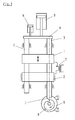
- the present invention relates to a flash butt welding machine having a drive comprising a servomotor with a cam mechanism coupled to the drive, a first holding means for holding a first joining partner, which is connected to a scanner of the cam mechanism, and a second holding means for holding a second joining partner.
- a flash butt welding machine of this type is manufactured and sold by the IDEAL plant C. & E. Jungeblodt GmbH & Co. KG, Lippstadt, Germany, under the name BAS and other names for decades.
- a flash butt welding machine of a similar type is also disclosed, for example, in the publication DE 22 33 647 described.
- a cam of the cam gear is driven by an electric motor at a constant speed.
- the movement of the first holding means is programmed.
- the curve has various sections, each associated with a step of flash butt welding.
- up to seven sections can be distinguished, which differ in the slope of the curve per degree of angle.
- Such a flash butt welding machine may be used after welding of the joining partners to anneal the weld to remove stresses.
- the workpiece is with re-clamped a greater distance of the holding means.
- the first holding means is decoupled from the drive, so that the first holding means is freely movable, whereby distortions are avoided, which could arise when the workpiece is clamped at a fixed distance of the holding means.
- a programmable controller makes it possible to perform a variety of different welding operations, without the need to replace components of the machine.
- a flash butt welding machine with a servomotor and a spindle has a disadvantage compared to a machine with a cam, which is that the upsetting impact with which the can be beaten together to be welded surfaces of the joining partners, compared to a machine with a cam can be done only slowly.
- the propulsion of one joining partner against the other is advantageously not linear.
- a quick upset stroke can only be achieved by disengaging the spindle and the nut engaging in the spindle, so that the movable, coupled to the mother holding means for one of the joining partners is driven independently of the movement of the servomotor and moved for the upsetting blow can be. If you can disengage the nut and the spindle, also a free movement of the holding means during annealing is possible.
- a flash butt welding machine of the type mentioned is from the JP 9 024477 A known.
- a servomotor is coupled to a cam gear having a translationally movable cam body.
- the cam body of the cam gear comprises a sectionally curved trained Outer surface, which cooperates with a scanner, which in turn is connected to a holding means for a first mating partner.
- a drive which comprises a servo motor with which a cam body of the cam gear is driven.
- the sequence of the welding process is thereby dictated both by the movement of the cam body driven by the servomotor and by the curve on the cam body.
- the programming of the machine can thereby by a driving of the Servo motor done.
- the machine is partly determined by the curve of the cam.
- the upset stroke can be programmed in the cam body.
- This fast-forwarding of the scanner and consequently of the first holding means can also be effected according to the invention by a first section of the curve which has an infinite, an almost infinite or, compared to other sections of the curve, a much greater gradient.
- the machine according to the invention according to claim 2 has a control and / or regulating means with which a rotation of the servomotor and the cam body coupled thereto can be controlled and / or regulated.
- the control and / or regulating means is programmable. Alternatively or additionally, it is possible to select between programs of the control and / or regulating means. With the programs, a desired movement of the cam can be specified, which in combination with the curve of the cam and the movement of the first holding means is specified.
- the curve may have further sections. These further sections may also contain a programming of the machine according to the invention.
- the machine according to the invention comprises a cam with a curve having at least one second section with a consistent positive slope.
- the curve of the Kurvenköpers, in a third section have a constant negative slope.
- the movement of the cam body is effected by the servomotor, and therefore variation of the movement of the cam body caused by the servo motor affects the movement of the cam in addition to the specifications of the cam.
- the curve of the cam body fundamental movements can be programmed in a simple manner, while a more accurate specification of the movement can be achieved by a control of the servomotor.
- the first section, the second section and the third section or the shoulder of the curve of the cam body may lie directly or indirectly behind one another.
- the at least one program of the control and / or regulating means may for example specify a desired movement of the cam body, in which the cam body is accelerated and / or braked during a program run.
- a machine may comprise at least one spring and / or at least one linear drive which is coupled to the first holding means.
- the spring or the linear drive By means of the spring or the linear drive, the first holding means is acted upon by a force such that the scanner, which is connected to the first holding means, bears against the curve of the cam body.
- the necessary force can be provided to perform the upset stroke when the first section or the shoulder of the curve is reached.
- the spring may be a tortuous torsion spring.
- the linear drive can be a pneumatic drive or a hydraulic drive.
- drives are provided for the contact between the scanner and the cam and for the upsetting impact, these can provide forces in the same direction or in opposite directions.
- the drives may be locked against each other so that they do not simultaneously provide power and one drive is off when the other is on.
Landscapes
- Engineering & Computer Science (AREA)
- Mechanical Engineering (AREA)
- Pressure Welding/Diffusion-Bonding (AREA)
- Transmission Devices (AREA)
- Resistance Welding (AREA)
Applications Claiming Priority (2)
| Application Number | Priority Date | Filing Date | Title |
|---|---|---|---|
| DE202011050606U DE202011050606U1 (de) | 2011-07-01 | 2011-07-01 | Abbrennstumpfschweißmaschine |
| EP12168782.6A EP2540431B1 (fr) | 2011-07-01 | 2012-05-22 | Machine à souder par étincelage avec un système à came entrainé par un servomoteur |
Related Parent Applications (2)
| Application Number | Title | Priority Date | Filing Date |
|---|---|---|---|
| EP12168782.6A Division EP2540431B1 (fr) | 2011-07-01 | 2012-05-22 | Machine à souder par étincelage avec un système à came entrainé par un servomoteur |
| EP12168782.6A Division-Into EP2540431B1 (fr) | 2011-07-01 | 2012-05-22 | Machine à souder par étincelage avec un système à came entrainé par un servomoteur |
Publications (1)
| Publication Number | Publication Date |
|---|---|
| EP2835208A1 true EP2835208A1 (fr) | 2015-02-11 |
Family
ID=44974220
Family Applications (2)
| Application Number | Title | Priority Date | Filing Date |
|---|---|---|---|
| EP12168782.6A Active EP2540431B1 (fr) | 2011-07-01 | 2012-05-22 | Machine à souder par étincelage avec un système à came entrainé par un servomoteur |
| EP14185059.4A Withdrawn EP2835208A1 (fr) | 2011-07-01 | 2012-05-22 | Machine à souder par étincelage avec une câme comprenant un corps courbé |
Family Applications Before (1)
| Application Number | Title | Priority Date | Filing Date |
|---|---|---|---|
| EP12168782.6A Active EP2540431B1 (fr) | 2011-07-01 | 2012-05-22 | Machine à souder par étincelage avec un système à came entrainé par un servomoteur |
Country Status (5)
| Country | Link |
|---|---|
| EP (2) | EP2540431B1 (fr) |
| DE (1) | DE202011050606U1 (fr) |
| DK (1) | DK2540431T3 (fr) |
| ES (1) | ES2641932T3 (fr) |
| PL (1) | PL2540431T3 (fr) |
Families Citing this family (4)
| Publication number | Priority date | Publication date | Assignee | Title |
|---|---|---|---|---|
| CN110253126B (zh) * | 2019-07-23 | 2024-01-12 | 上海嘉朗实业南通智能科技有限公司 | 一种半自动闪光对焊机 |
| DE102022112795B4 (de) | 2022-05-20 | 2024-05-16 | WIKUS-Sägenfabrik Wilhelm H. Kullmann GmbH & Co. KG | Band-Abbrennstumpfschweißmaschine,Anbaugruppe für eine Band-Abbrennstumpfschweißmaschine und Anordnung |
| EP4526073A1 (fr) | 2022-05-20 | 2025-03-26 | WIKUS-Sägenfabrik Wilhelm H. Kullmann GmbH & Co. KG | Machine de soudage en bout par étincelage de bande et groupe d'accessoires pour une machine de soudage en bout par étincelage de bande |
| DE102022112796B4 (de) | 2022-05-20 | 2025-09-04 | Ideal - Werk C. + E. Jungeblodt Gmbh + Co. Kg | Band-Abbrennstumpfschweißmaschine |
Citations (5)
| Publication number | Priority date | Publication date | Assignee | Title |
|---|---|---|---|---|
| US2085049A (en) * | 1936-01-17 | 1937-06-29 | Thompson Prod Inc | Machine for making flash butt welds |
| US2435026A (en) * | 1944-06-26 | 1948-01-27 | Bailey Meter Co | Welding control system |
| DE2233647A1 (de) | 1972-07-08 | 1974-01-24 | August Strecker Kg | Abbrennstumpfschweissmaschine |
| JPH0924477A (ja) | 1995-07-10 | 1997-01-28 | Sankoole Kk | 被溶接物の溶接状態の評価装置及びその評価方法 |
| US20040188392A1 (en) | 2003-03-24 | 2004-09-30 | James Campbell | Resistance butt flash welding |
-
2011
- 2011-07-01 DE DE202011050606U patent/DE202011050606U1/de not_active Expired - Lifetime
-
2012
- 2012-05-22 ES ES12168782.6T patent/ES2641932T3/es active Active
- 2012-05-22 DK DK12168782.6T patent/DK2540431T3/en active
- 2012-05-22 PL PL12168782T patent/PL2540431T3/pl unknown
- 2012-05-22 EP EP12168782.6A patent/EP2540431B1/fr active Active
- 2012-05-22 EP EP14185059.4A patent/EP2835208A1/fr not_active Withdrawn
Patent Citations (5)
| Publication number | Priority date | Publication date | Assignee | Title |
|---|---|---|---|---|
| US2085049A (en) * | 1936-01-17 | 1937-06-29 | Thompson Prod Inc | Machine for making flash butt welds |
| US2435026A (en) * | 1944-06-26 | 1948-01-27 | Bailey Meter Co | Welding control system |
| DE2233647A1 (de) | 1972-07-08 | 1974-01-24 | August Strecker Kg | Abbrennstumpfschweissmaschine |
| JPH0924477A (ja) | 1995-07-10 | 1997-01-28 | Sankoole Kk | 被溶接物の溶接状態の評価装置及びその評価方法 |
| US20040188392A1 (en) | 2003-03-24 | 2004-09-30 | James Campbell | Resistance butt flash welding |
Also Published As
| Publication number | Publication date |
|---|---|
| PL2540431T3 (pl) | 2018-01-31 |
| ES2641932T3 (es) | 2017-11-14 |
| EP2540431A1 (fr) | 2013-01-02 |
| DK2540431T3 (en) | 2017-10-16 |
| EP2540431B1 (fr) | 2017-08-02 |
| DE202011050606U1 (de) | 2011-10-17 |
Similar Documents
| Publication | Publication Date | Title |
|---|---|---|
| EP2218534B1 (fr) | Dispositif de traitement de dents de scie d'une lame de scie | |
| DE102011082903A1 (de) | Gewindewirbelvorrichtung und Drehmaschine umfassend eine Gewindewirbelvorrichtung | |
| DE102017121526A1 (de) | Vorrichtung zur Ausrichtung und Positionierung eines Werkstücks relativ zu einem Laserstrahl einer Laserbearbeitungsmaschine | |
| DE10024990C5 (de) | Verfahren und Vorrichtung zum induktiven Härten von Kurbelwellen | |
| EP2835208A1 (fr) | Machine à souder par étincelage avec une câme comprenant un corps courbé | |
| EP2011595A1 (fr) | Agencement de chariot pour une machine-outil | |
| EP2813314A1 (fr) | Outil et procédé de friction-malaxage pour une pièce comprenant un revêtement | |
| EP3162496B1 (fr) | Dispositif d'assemblage de plusieurs éléments fonctionnels sur un arbre | |
| EP3093088A1 (fr) | Dispositif de serrage de piece comprenant un chalutier frontal | |
| EP2218525B1 (fr) | Dispositif d'avance de fil | |
| EP3620251A1 (fr) | Procédé d'usinage de denture d'une pièce à usiner, machine à tailler les engrenages et logiciel correspondant | |
| EP2995417B1 (fr) | Dispositif de montage d'au moins un element fonctionnel presentant un evidement pour un arbre | |
| EP2724801A1 (fr) | Agrégat de serrage | |
| DE2829152A1 (de) | Verfahren zum einspannen von werkstuecken an kegelfoermigen flaechen mittels kraftspannfutter und kraftspannfutter hierzu | |
| EP2755784B1 (fr) | Module d'outils destiné à un dispositif de tournage | |
| EP3546084B1 (fr) | Procédé de liaison d'au moins deux composants au moyen d'un dispositif de rivetage et dispositif de rivetage | |
| DE102009049861A1 (de) | Vorrichtung und Verfahren zum Entgraten und/oder Anfasen von Werkstücken | |
| DE102015216531A1 (de) | Aussteuerwerkzeug | |
| EP3178599B1 (fr) | Machine sur colonne | |
| DE102024106540B4 (de) | Vorrichtung zum ausbilden, formen und richten eines werkstücks | |
| EP3145657A1 (fr) | Procédé de liaison d'au moins deux éléments structuraux ainsi que dispositif pour la mise en oeuvre d'un tel procédé | |
| DE102014119166B4 (de) | Schleifmaschine | |
| DE102013003771A1 (de) | Verzahnmaschine zum Bearbeiten eines Werkstücks und Vefahren zum Bearbeiten einer Kurbelwelle | |
| WO2024002582A1 (fr) | Stratégie de forgeage de smx | |
| AT503471B1 (de) | Verfahren und vorrichtung zum verbinden von metallischen elementen nach der reibschweissmethode |
Legal Events
| Date | Code | Title | Description |
|---|---|---|---|
| PUAI | Public reference made under article 153(3) epc to a published international application that has entered the european phase |
Free format text: ORIGINAL CODE: 0009012 |
|
| 17P | Request for examination filed |
Effective date: 20140917 |
|
| AC | Divisional application: reference to earlier application |
Ref document number: 2540431 Country of ref document: EP Kind code of ref document: P |
|
| AK | Designated contracting states |
Kind code of ref document: A1 Designated state(s): AL AT BE BG CH CY CZ DE DK EE ES FI FR GB GR HR HU IE IS IT LI LT LU LV MC MK MT NL NO PL PT RO RS SE SI SK SM TR |
|
| R17P | Request for examination filed (corrected) |
Effective date: 20150626 |
|
| RBV | Designated contracting states (corrected) |
Designated state(s): AL AT BE BG CH CY CZ DE DK EE ES FI FR GB GR HR HU IE IS IT LI LT LU LV MC MK MT NL NO PL PT RO RS SE SI SK SM TR |
|
| 17Q | First examination report despatched |
Effective date: 20151120 |
|
| GRAP | Despatch of communication of intention to grant a patent |
Free format text: ORIGINAL CODE: EPIDOSNIGR1 |
|
| INTG | Intention to grant announced |
Effective date: 20160808 |
|
| STAA | Information on the status of an ep patent application or granted ep patent |
Free format text: STATUS: THE APPLICATION HAS BEEN WITHDRAWN |
|
| 18W | Application withdrawn |
Effective date: 20161216 |