EP2839242B1 - Procédé de mesure sur une machine-outil et machine-outil correspondante - Google Patents
Procédé de mesure sur une machine-outil et machine-outil correspondante Download PDFInfo
- Publication number
- EP2839242B1 EP2839242B1 EP13719597.0A EP13719597A EP2839242B1 EP 2839242 B1 EP2839242 B1 EP 2839242B1 EP 13719597 A EP13719597 A EP 13719597A EP 2839242 B1 EP2839242 B1 EP 2839242B1
- Authority
- EP
- European Patent Office
- Prior art keywords
- measurement
- analogue probe
- probe
- preferred
- range
- Prior art date
- Legal status (The legal status is an assumption and is not a legal conclusion. Google has not performed a legal analysis and makes no representation as to the accuracy of the status listed.)
- Active
Links
Images


Classifications
-
- G—PHYSICS
- G05—CONTROLLING; REGULATING
- G05B—CONTROL OR REGULATING SYSTEMS IN GENERAL; FUNCTIONAL ELEMENTS OF SUCH SYSTEMS; MONITORING OR TESTING ARRANGEMENTS FOR SUCH SYSTEMS OR ELEMENTS
- G05B19/00—Program-control systems
- G05B19/02—Program-control systems electric
- G05B19/18—Numerical control [NC], i.e. automatically operating machines, in particular machine tools, e.g. in a manufacturing environment, so as to execute positioning, movement or co-ordinated operations by means of program data in numerical form
- G05B19/401—Numerical control [NC], i.e. automatically operating machines, in particular machine tools, e.g. in a manufacturing environment, so as to execute positioning, movement or co-ordinated operations by means of program data in numerical form characterised by control arrangements for measuring, e.g. calibration and initialisation, measuring workpiece for machining purposes
-
- G—PHYSICS
- G01—MEASURING; TESTING
- G01B—MEASURING LENGTH, THICKNESS OR SIMILAR LINEAR DIMENSIONS; MEASURING ANGLES; MEASURING AREAS; MEASURING IRREGULARITIES OF SURFACES OR CONTOURS
- G01B21/00—Measuring arrangements or details thereof, where the measuring technique is not covered by the other groups of this subclass, unspecified or not relevant
- G01B21/02—Measuring arrangements or details thereof, where the measuring technique is not covered by the other groups of this subclass, unspecified or not relevant for measuring length, width, or thickness
- G01B21/04—Measuring arrangements or details thereof, where the measuring technique is not covered by the other groups of this subclass, unspecified or not relevant for measuring length, width, or thickness by measuring coordinates of points
- G01B21/045—Correction of measurements
-
- G—PHYSICS
- G05—CONTROLLING; REGULATING
- G05B—CONTROL OR REGULATING SYSTEMS IN GENERAL; FUNCTIONAL ELEMENTS OF SUCH SYSTEMS; MONITORING OR TESTING ARRANGEMENTS FOR SUCH SYSTEMS OR ELEMENTS
- G05B2219/00—Program-control systems
- G05B2219/30—Nc systems
- G05B2219/50—Machine tool, machine tool null till machine tool work handling
- G05B2219/50063—Probe, measure, verify workpiece, feedback measured values
Definitions
- analogue probes have not been widely used for machine tool scanning applications. This is due to the inherent nature of many commercially available machine tools which do not facilitate the real-time control of the analogue probe that CMMs provide. This is because machine tools are primarily developed to machine workpieces and the use of measurement probes on them to measure workpieces is essentially an after-thought. Machine tools are therefore typically not configured for real-time control using data from an analogue measurement probe. Indeed, it is often the case that the machine tool has no in-built provision for the direct receipt of deflection data from the measurement probe. Rather, the probe has to communicate (e.g. wirelessly) with an interface which receives the probe deflection data and passes the data to a separate system which subsequently combines the deflection data with machine position data so as to subsequently form complete object measurement data, for instance as described in WO2005/065884 .
- the problem can also be further compounded when using analogue probes on machine tools because due to their construction (which enables them to be used within the harsher environments that machine tools provide and the greater accelerations and forces they are exposed to such as when they are auto-changed into/out of a machine tool's spindle) they often have a much smaller measurement range than those analogue probes which are for use with CMMs. This can therefore give even less room for error compared to analogue probes used on CMMs.
- the analogue probe is a contact analogue probe with a deflectable stylus for contacting the object.
- the preferred measurement range can be a preferred stylus deflection range. Accordingly, the preferred measurement range could comprise upper and lower boundaries or thresholds relating to maximum and minimum stylus deflections.
- the analogue probe could be a sealed analogue probe. That is the analogue probe could be sealed so as to protect internal sensor componentry from external contaminants.
- the probe could comprise a probe body which houses a sensor for either directly or indirectly measuring the surface of an object, in which the sensor is sealed from external contaminant.
- the probe in the case of a contact probe, could comprise a probe body, a stylus member and a sensor for measuring displacement of the stylus member relative to the housing, in which at least a first compliant sealing member is provided which extends between the probe body and relatively moveable stylus member, such that the sensor is contained within a sealed chamber and thereby sealed from external contaminants.
- the probe is configured such that it is most accurate when the stylus is deflected by an amount less than the maximum physical deflection. It could also be that the probe is configured such that it is most accurate when the stylus is deflected by a minimum lower threshold.
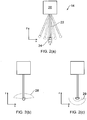
- the analogue probe 14 could have a preferred measurement range, the upper and lower boundaries of which are shown by stylus positions shown in Figure 2(a) as dotted lines. Accordingly, as can be seen there is a dead space 'd' (in the x-dimension) in the middle close to the stylus' rest position which is outside the preferred measuring range.
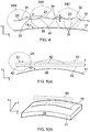
- the amplitude A of undulating position of the stylus centre tip is greatly exaggerated in Figure 4 so as to aid illustration.
- the extent of the amplitude A will vary depending on many factors including the extent of the preferred measurement range, the extent the actual physical range of a deflectable stylus, the nominal workpiece dimensions and the expected level of variation in surface position. Nevertheless, by way of example only, the amplitude A can be as less than 5mm, for example less than 2mm, and for example greater than 0.5mm, for example 1mm.
- the pitch P of the undulating motion will vary depending on many factors, such as those mentioned above and for example the density of measurements required, and for example can be less than 100mm and for example greater than 10mm, for example 50mm.
Landscapes
- Engineering & Computer Science (AREA)
- Physics & Mathematics (AREA)
- General Physics & Mathematics (AREA)
- Human Computer Interaction (AREA)
- Manufacturing & Machinery (AREA)
- Automation & Control Theory (AREA)
- A Measuring Device Byusing Mechanical Method (AREA)
- Length Measuring Devices With Unspecified Measuring Means (AREA)
- Machine Tool Sensing Apparatuses (AREA)
Claims (15)
- Procédé de balayage d'un objet (16) utilisant un palpeur analogique à contact (14) comprenant un stylet fléchissable (22) pour entrer en contact avec l'objet monté sur une machine-outil (3), afin de collecter des données de mesure balayées sur une ligne de mesure nominale (19) sur la surface (17) de l'objet, le palpeur analogique ayant une plage de mesure préférée, le procédé consistant à :commander le palpeur analogique à contact et/ou l'objet pour réaliser une opération de balayage conformément à un processus de mouvement relatif, le processus de mouvement relatif étant configuré de manière à ce que, sur la base des propriétés supposées de la surface de l'objet, la palpeur analogique sera destiné à obtenir des données dans sa plage de mesure préférée, le palpeur analogique étant également destiné à sortir de sa plage de mesure préférée, sur la ligne de mesure nominale sur la surface de l'objet.
- Procédé selon la revendication 1, consistant à effectuer une collecte et un envoi des données de mesure balayées obtenues dans la plage de mesure préférée du palpeur analogique à contact comme étant la mesure de l'objet.
- Procédé selon la revendication 2, dans lequel lesdits collecte et envoi mettent enjeu un filtrage (110) des données obtenues du palpeur analogique à contact afin d'obtenir, et de fournir comme mesure de l'objet, des données de mesure d'objet sélectives obtenues dans le cadre de la plage de mesure préférée du palpeur analogique à contact.
- Procédé selon l'une quelconque des revendications précédentes, dans lequel le palpeur analogique à contact procède suivant une manière qui, sur la base des propriétés supposées de la surface de l'objet, fait que la position de la plage de mesure préférée du palpeur analogique à contact monte et descende de manière répétée par rapport à la surface de l'objet à mesure qu'il se déplace sur la ligne de mesure nominale.
- Procédé selon l'une quelconque des revendications précédentes, dans lequel le palpeur analogique à contact est maintenu dans un rapport de détection de position avec la surface de l'objet à mesure qu'il est déplacé afin de collecter des données sur la ligne de mesure nominale.
- Procédé selon l'une quelconque des revendications précédentes, dans lequel le processus de mouvement relatif est configuré pour que, pendant l'opération de balayage, la plage de mesure préférée du palpeur analogique à contact traverse plusieurs fois l'objet sur la ligne de mesure nominale.
- Procédé selon la revendication 6, dans lequel pour différents mouvements transversaux le palpeur analogique à contact obtient des données de mesure dans le cadre de sa plage de mesure préférée pour différentes parties de l'objet sur la ligne de mesure nominale.
- Procédé selon la revendication 6 ou 7, dans lequel la forme du trajet que prend la plage de mesure préférée par rapport à la surface est sensiblement la même pour des mouvements transversaux successifs, mais, dans lequel la hauteur du trajet partant de la surface au niveau d'au moins un point le long de la ligne de mesure préférée est différente pour différents mouvements transversaux.
- Procédé selon l'une quelconque des revendications 6 à 8, dans lequel les données de mesure de surface obtenues dans la plage de mesure préférée à partir de différents mouvements transversaux sont compilées afin de constituer un ensemble de données de mesure représentant la surface de l'objet sur la ligne de mesure nominale.
- Procédé selon la revendication 1, comprenant la génération et l'exécution, dans le cadre d'une deuxième opération de balayage, un nouveau processus de mouvement relatif du palpeur analogique et de l'objet.
- Procédé selon la revendication 10, dans lequel le nouveau processus de mouvement relatif consiste à faire que le palpeur analogique à contact traverse sensiblement la même ligne de mesure sur la surface de l'objet, mais dans lequel le mouvement relatif est commandé de manière à ce que le palpeur analogique à contact obtienne les mesures dans le cadre de sa plage de mesure préférée pour une plus grande partie du processus de mouvement que pour celle de l'opération de balayage.
- Procédé selon l'une quelconque des revendications précédentes, dans lequel la plage de mesure préférée du palpeur analogique à contact est une plage préférée de fléchissement du palpeur analogique à contact.
- Logiciel comprenant des instructions qui, quand elles sont exécutées sur un appareil de machine-outil, font que l'appareil de machine-outil exécute le procédé de l'une quelconque des revendications précédentes.
- Support lisible par ordinateur comprenant des instructions qui, quand elles sont exécutées sur un appareil de machine-outil, font que l'appareil de machine-outil réalise le procédé de l'une quelconque des revendications précédentes 1 à 12.
- Appareil de machine-outil (2) comprenant une machine-outil (4), un palpeur analogique à contact (14) ayant un stylet fléchissable (22) monté sur la machine-outil, et un contrôleur (6) configuré pour commander le mouvement relatif du palpeur analogique à contact et d'un objet (16) à mesurer afin de collecter des données de mesure balayées sur une ligne de mesure nominale (19) sur la surface (17) de l'objet, et afin de commander le palpeur analogique à contact et/ou l'objet conformément à un processus de mouvement relatif de manière à ce que la position de la plage de mesure préférée par rapport à la surface de l'objet soit commandée d'une manière qui, sur la base des propriétés supposées de la surface de l'objet, fera que le palpeur analogique à contact obtienne les données dans sa plage de mesure préférée, et de même qu'il dépasse sa plage de mesure préférée sur la ligne de mesure nominale sur la surface de l'objet.
Priority Applications (2)
| Application Number | Priority Date | Filing Date | Title |
|---|---|---|---|
| EP17174417.0A EP3239653B1 (fr) | 2012-04-18 | 2013-04-16 | Procédé de mesure sur une machine-outil et machine-outil correspondante |
| EP13719597.0A EP2839242B1 (fr) | 2012-04-18 | 2013-04-16 | Procédé de mesure sur une machine-outil et machine-outil correspondante |
Applications Claiming Priority (4)
| Application Number | Priority Date | Filing Date | Title |
|---|---|---|---|
| EP12250096 | 2012-04-18 | ||
| US201261720293P | 2012-10-30 | 2012-10-30 | |
| PCT/GB2013/050968 WO2013156769A1 (fr) | 2012-04-18 | 2013-04-16 | Procédé de mesure sur une machine-outil et appareil de machine-outil correspondant |
| EP13719597.0A EP2839242B1 (fr) | 2012-04-18 | 2013-04-16 | Procédé de mesure sur une machine-outil et machine-outil correspondante |
Related Child Applications (2)
| Application Number | Title | Priority Date | Filing Date |
|---|---|---|---|
| EP17174417.0A Division-Into EP3239653B1 (fr) | 2012-04-18 | 2013-04-16 | Procédé de mesure sur une machine-outil et machine-outil correspondante |
| EP17174417.0A Division EP3239653B1 (fr) | 2012-04-18 | 2013-04-16 | Procédé de mesure sur une machine-outil et machine-outil correspondante |
Publications (2)
| Publication Number | Publication Date |
|---|---|
| EP2839242A1 EP2839242A1 (fr) | 2015-02-25 |
| EP2839242B1 true EP2839242B1 (fr) | 2017-08-02 |
Family
ID=49382988
Family Applications (2)
| Application Number | Title | Priority Date | Filing Date |
|---|---|---|---|
| EP13719597.0A Active EP2839242B1 (fr) | 2012-04-18 | 2013-04-16 | Procédé de mesure sur une machine-outil et machine-outil correspondante |
| EP17174417.0A Active EP3239653B1 (fr) | 2012-04-18 | 2013-04-16 | Procédé de mesure sur une machine-outil et machine-outil correspondante |
Family Applications After (1)
| Application Number | Title | Priority Date | Filing Date |
|---|---|---|---|
| EP17174417.0A Active EP3239653B1 (fr) | 2012-04-18 | 2013-04-16 | Procédé de mesure sur une machine-outil et machine-outil correspondante |
Country Status (6)
| Country | Link |
|---|---|
| US (2) | US10037017B2 (fr) |
| EP (2) | EP2839242B1 (fr) |
| JP (2) | JP6345171B2 (fr) |
| CN (2) | CN104487801B (fr) |
| TW (2) | TWI649537B (fr) |
| WO (1) | WO2013156769A1 (fr) |
Families Citing this family (24)
| Publication number | Priority date | Publication date | Assignee | Title |
|---|---|---|---|---|
| WO2009049272A2 (fr) | 2007-10-10 | 2009-04-16 | Gerard Dirk Smits | Projecteur d'image avec suivi de lumière réfléchie |
| US9946076B2 (en) | 2010-10-04 | 2018-04-17 | Gerard Dirk Smits | System and method for 3-D projection and enhancements for interactivity |
| US12025807B2 (en) | 2010-10-04 | 2024-07-02 | Gerard Dirk Smits | System and method for 3-D projection and enhancements for interactivity |
| US8971568B1 (en) * | 2012-10-08 | 2015-03-03 | Gerard Dirk Smits | Method, apparatus, and manufacture for document writing and annotation with virtual ink |
| WO2015149027A1 (fr) | 2014-03-28 | 2015-10-01 | Gerard Dirk Smits | Système de projection intelligent monté sur tête |
| JP6385149B2 (ja) * | 2014-06-13 | 2018-09-05 | キヤノン株式会社 | 形状測定方法、形状測定装置、プログラム及び記録媒体 |
| WO2016025502A1 (fr) | 2014-08-11 | 2016-02-18 | Gerard Dirk Smits | Systèmes et procédés de poursuite à base de triangulation tridimensionnelle et de temps de vol |
| GB201505999D0 (en) | 2015-04-09 | 2015-05-27 | Renishaw Plc | Measurement method and apparatus |
| US10043282B2 (en) | 2015-04-13 | 2018-08-07 | Gerard Dirk Smits | Machine vision for ego-motion, segmenting, and classifying objects |
| WO2017106875A1 (fr) | 2015-12-18 | 2017-06-22 | Gerard Dirk Smits | Détection de position en temps réel d'objets |
| US9813673B2 (en) | 2016-01-20 | 2017-11-07 | Gerard Dirk Smits | Holographic video capture and telepresence system |
| GB201615307D0 (en) * | 2016-09-09 | 2016-10-26 | Renishaw Plc | Measurement method and apparatus |
| GB201616415D0 (en) * | 2016-09-28 | 2016-11-09 | Renishaw Plc | A method and apparatus for measuring an object |
| CN110073243B (zh) | 2016-10-31 | 2023-08-04 | 杰拉德·迪尔克·施密茨 | 利用动态体素探测的快速扫描激光雷达 |
| EP3563347A4 (fr) | 2016-12-27 | 2020-06-24 | Gerard Dirk Smits | Systèmes et procédés pour la perception par les machines |
| WO2018209096A2 (fr) | 2017-05-10 | 2018-11-15 | Gerard Dirk Smits | Procédés et systèmes à miroir de balayage |
| US10591605B2 (en) | 2017-10-19 | 2020-03-17 | Gerard Dirk Smits | Methods and systems for navigating a vehicle including a novel fiducial marker system |
| US10379220B1 (en) | 2018-01-29 | 2019-08-13 | Gerard Dirk Smits | Hyper-resolved, high bandwidth scanned LIDAR systems |
| GB201809631D0 (en) * | 2018-06-12 | 2018-07-25 | Renishaw Plc | Measurement method and apparatus |
| EP3623883B1 (fr) | 2018-09-17 | 2024-07-24 | Adelbert Haas GmbH | Procédé et machine-outil destinée au traitement de pièces à usiner de géométrie inconnue |
| CN113116337B (zh) * | 2019-02-25 | 2022-05-13 | 无锡市第二人民医院 | 一种全身体检数据自动采集方法 |
| WO2021090693A1 (fr) * | 2019-11-05 | 2021-05-14 | パナソニックIpマネジメント株式会社 | Procédé de commande de robot |
| WO2021174227A1 (fr) | 2020-02-27 | 2021-09-02 | Gerard Dirk Smits | Balayage à haute résolution d'objets distants avec des faisceaux laser panoramiques rapides et récupération de signal par réseau de pixels agité |
| GB202012104D0 (en) * | 2020-08-04 | 2020-09-16 | Renishaw Plc | Measurement method |
Family Cites Families (68)
| Publication number | Priority date | Publication date | Assignee | Title |
|---|---|---|---|---|
| US4153998A (en) | 1972-09-21 | 1979-05-15 | Rolls-Royce (1971) Limited | Probes |
| US4166323A (en) | 1973-09-14 | 1979-09-04 | Maag Gear-Wheel & Machine Co. Ltd. | Gear tester for profile and lead testing |
| GB1551218A (en) * | 1975-05-13 | 1979-08-22 | Rolls Royce | Probe for use in displacement measuring apparatus |
| GB2174216B (en) | 1985-03-19 | 1988-10-26 | Mitutoyo Mfg Co Ltd | Method of operating a coordinate measuring instrument |
| CN85105480A (zh) * | 1985-07-17 | 1987-01-14 | 通用电气公司 | 针尖接触式探测系统 |
| GB8713715D0 (en) * | 1987-06-11 | 1987-07-15 | Renishaw Plc | Workpiece inspection method |
| JPH02145908A (ja) | 1988-11-28 | 1990-06-05 | Okuma Mach Works Ltd | デジタイジング装置におけるスタイラスのたわみ補正自動設定方法 |
| US5189806A (en) * | 1988-12-19 | 1993-03-02 | Renishaw Plc | Method of and apparatus for scanning the surface of a workpiece |
| GB8908854D0 (en) | 1989-04-19 | 1989-06-07 | Renishaw Plc | Method of and apparatus for scanning the surface of a workpiece |
| GB9110818D0 (en) | 1991-05-21 | 1991-07-10 | Renishaw Metrology Ltd | A method of measuring workpieces using a surface contacting measuring probe |
| DE4245012B4 (de) * | 1992-04-14 | 2004-09-23 | Carl Zeiss | Verfahren zur Messung von Formelementen auf einem Koordinatenmeßgerät |
| EP0588512B1 (fr) * | 1992-09-12 | 1997-04-09 | RENISHAW plc | Procédé et appareil pour explorer la surface d'une pièce |
| US5440398A (en) * | 1993-02-25 | 1995-08-08 | Ohio Electronic Engravers, Inc. | Error detection apparatus and method for use with engravers |
| US5948972A (en) * | 1994-12-22 | 1999-09-07 | Kla-Tencor Corporation | Dual stage instrument for scanning a specimen |
| GB2302589B (en) | 1995-06-21 | 1998-11-11 | Zeiss Stiftung | Probe head for coordinate measuring machines with a clamping device for clamping the deflectable part of the probe head |
| DE19730471C5 (de) | 1997-07-16 | 2009-02-19 | Hexagon Metrology Gmbh | Verfahren zum Scannen mit einem Koordinatenmeßgerät |
| US6580964B2 (en) * | 1998-10-24 | 2003-06-17 | Renishaw Plc | Calibrations of an analogue probe and error mapping |
| JP4660779B2 (ja) | 2000-08-18 | 2011-03-30 | 学校法人 中央大学 | 移動装置の位置誤差評価方法およびその評価結果に基づく移動精度向上方法 |
| JP3905771B2 (ja) | 2001-03-02 | 2007-04-18 | 株式会社ミツトヨ | 測定機の校正方法及び装置 |
| GB0118492D0 (en) | 2001-07-30 | 2001-09-19 | Renishaw Plc | A machine tool control process and apparatus therfor |
| GB0126232D0 (en) | 2001-11-01 | 2002-01-02 | Renishaw Plc | Calibration of an analogue probe |
| GB0210990D0 (en) | 2002-05-14 | 2002-06-19 | Rolls Royce Plc | Method of generating an inspection program and method of generating a visual display |
| GB0215152D0 (en) | 2002-07-01 | 2002-08-07 | Renishaw Plc | Probe or stylus orientation |
| GB0215478D0 (en) * | 2002-07-04 | 2002-08-14 | Renishaw Plc | Method of scanning a calibrating system |
| GB0220158D0 (en) | 2002-08-30 | 2002-10-09 | Renishaw Plc | Method of scanning |
| CN1297796C (zh) * | 2003-07-02 | 2007-01-31 | 西安交通大学 | 线阵光电传感器层析扫描三维测量方法及其装置 |
| GB0322115D0 (en) | 2003-09-22 | 2003-10-22 | Renishaw Plc | Method of error compensation |
| GB0322362D0 (en) * | 2003-09-24 | 2003-10-22 | Renishaw Plc | Measuring methods for use on machine tools |
| GB0329098D0 (en) | 2003-12-16 | 2004-01-21 | Renishaw Plc | Method of calibrating a scanning system |
| US7543393B2 (en) | 2003-12-16 | 2009-06-09 | Renishaw Plc | Method of calibrating a scanning system |
| GB0400144D0 (en) | 2004-01-06 | 2004-02-11 | Renishaw Plc | Inspection system |
| CN1727871A (zh) | 2004-01-14 | 2006-02-01 | Fei公司 | 探针显微镜的操作方法 |
| EP1555676A3 (fr) | 2004-01-14 | 2006-09-13 | FEI Company | Méthode d'operation d'un micrscope à sonde |
| US20080021672A1 (en) * | 2004-03-18 | 2008-01-24 | Renishaw Plc | Scanning an Object |
| DE102004022454B4 (de) * | 2004-05-06 | 2014-06-05 | Carl Mahr Holding Gmbh | Messeinrichtung mit optischer Tastspitze |
| JP4782990B2 (ja) * | 2004-05-31 | 2011-09-28 | 株式会社ミツトヨ | 表面倣い測定装置、表面倣い測定方法、表面倣い測定プログラムおよび記録媒体 |
| JP4510520B2 (ja) | 2004-06-01 | 2010-07-28 | キヤノン株式会社 | 形状測定方法および形状測定装置 |
| GB0414649D0 (en) | 2004-06-30 | 2004-08-04 | Renishaw Plc | Generation of a CNC machine tool control program |
| GB0417536D0 (en) | 2004-08-06 | 2004-09-08 | Renishaw Plc | The use of surface measurement probes |
| GB2425840A (en) * | 2005-04-13 | 2006-11-08 | Renishaw Plc | Error correction of workpiece measurements |
| GB0508273D0 (en) | 2005-04-25 | 2005-06-01 | Renishaw Plc | Method for scanning the surface of a workpiece |
| GB0508395D0 (en) * | 2005-04-26 | 2005-06-01 | Renishaw Plc | Method for scanning the surface of a workpiece |
| US20070050089A1 (en) | 2005-09-01 | 2007-03-01 | Yunquan Sun | Method for detecting the position and orientation of holes using robotic vision system |
| GB0608235D0 (en) | 2006-04-26 | 2006-06-07 | Renishaw Plc | Differential calibration |
| GB0611109D0 (en) * | 2006-06-06 | 2006-07-19 | Renishaw Plc | A method for measuring workpieces |
| DE102006055005A1 (de) * | 2006-11-17 | 2008-05-29 | Carl Zeiss Industrielle Messtechnik Gmbh | Verfahren und Vorrichtung zum Bestimmen von Raumkoordinaten an einer Vielzahl von Messpunkten |
| GB0625260D0 (en) * | 2006-12-19 | 2007-01-24 | Renishaw Plc | A method for measuring a workpiece using a machine tool |
| GB0703423D0 (en) * | 2007-02-22 | 2007-04-04 | Renishaw Plc | Calibration method and apparatus |
| EP1978328B1 (fr) | 2007-04-03 | 2015-02-18 | Hexagon Metrology AB | Sonde à balayage oscillant avec force de contact constante |
| GB0707921D0 (en) * | 2007-04-24 | 2007-05-30 | Renishaw Plc | Apparatus and method for surface measurement |
| WO2008132483A1 (fr) * | 2007-04-30 | 2008-11-06 | Renishaw Plc | Sonde analogique et procédé de fonctionnement |
| EP1988357B1 (fr) * | 2007-05-04 | 2018-10-17 | Hexagon Technology Center GmbH | Procédé de mesure de coordonnées et dispositif |
| GB0713639D0 (en) | 2007-07-13 | 2007-08-22 | Renishaw Plc | Error correction |
| GB0716218D0 (en) | 2007-08-20 | 2007-09-26 | Renishaw Plc | Measurement path generation |
| JP5091702B2 (ja) * | 2008-02-04 | 2012-12-05 | 株式会社ミツトヨ | プローブの真直度測定方法 |
| US7752000B2 (en) | 2008-05-02 | 2010-07-06 | Qcept Technologies, Inc. | Calibration of non-vibrating contact potential difference measurements to detect surface variations that are perpendicular to the direction of sensor motion |
| JP4611403B2 (ja) | 2008-06-03 | 2011-01-12 | パナソニック株式会社 | 形状測定装置及び形状測定方法 |
| JP5684712B2 (ja) * | 2008-10-29 | 2015-03-18 | レニショウ パブリック リミテッド カンパニーRenishaw Public Limited Company | 座標測定システムのための方法 |
| GB0900878D0 (en) | 2009-01-20 | 2009-03-04 | Renishaw Plc | Method for optimising a measurement cycle |
| EP2290486A1 (fr) | 2009-08-28 | 2011-03-02 | Renishaw plc | Procédé d'étalonnage de machine-outil |
| JP5281992B2 (ja) * | 2009-08-28 | 2013-09-04 | 株式会社日立製作所 | 走査型プローブ顕微鏡及びそれを用いた計測方法 |
| JP5439157B2 (ja) * | 2009-12-22 | 2014-03-12 | 三菱重工業株式会社 | 歯車測定方法 |
| JP5690941B2 (ja) | 2010-09-13 | 2015-03-25 | ヘキサゴン・テクノロジー・センター・ゲーエムベーハーHexagon Technology Center Gmbh | 表面走査座標測定装置の制御方法及び制御装置 |
| JP6010046B2 (ja) * | 2011-01-19 | 2016-10-19 | レニショウ パブリック リミテッド カンパニーRenishaw Public Limited Company | 工作機械装置用のアナログ測定用プローブ |
| CN103842766B (zh) * | 2011-10-06 | 2017-05-24 | 瑞尼斯豪公司 | 测量方法 |
| EP2899501B1 (fr) * | 2011-12-06 | 2022-08-03 | Hexagon Technology Center GmbH | Machine de mesure de coordonnée dotée d'une caméra |
| EP2839240B1 (fr) | 2012-04-18 | 2017-09-06 | Renishaw PLC | Procédé de balayage de mesure analogique sur une machine-outil et machine-outil correspondante |
| EP2839241B1 (fr) | 2012-04-18 | 2018-08-08 | Renishaw PLC | Procédé pour la recherche d'une caractéristique d'un objet au moyen d'une machine-outil et dispositif de machine outil correspondant |
-
2013
- 2013-04-16 US US14/391,950 patent/US10037017B2/en active Active
- 2013-04-16 CN CN201380024772.2A patent/CN104487801B/zh active Active
- 2013-04-16 EP EP13719597.0A patent/EP2839242B1/fr active Active
- 2013-04-16 EP EP17174417.0A patent/EP3239653B1/fr active Active
- 2013-04-16 CN CN201811375373.1A patent/CN110076630B/zh active Active
- 2013-04-16 JP JP2015506301A patent/JP6345171B2/ja active Active
- 2013-04-16 WO PCT/GB2013/050968 patent/WO2013156769A1/fr not_active Ceased
- 2013-04-18 TW TW102113860A patent/TWI649537B/zh active
- 2013-04-18 TW TW105107808A patent/TWI675182B/zh active
-
2018
- 2018-05-22 JP JP2018097878A patent/JP6665227B2/ja active Active
- 2018-06-14 US US16/008,415 patent/US10678208B2/en active Active
Non-Patent Citations (1)
| Title |
|---|
| None * |
Also Published As
| Publication number | Publication date |
|---|---|
| EP2839242A1 (fr) | 2015-02-25 |
| JP6665227B2 (ja) | 2020-03-13 |
| CN104487801B (zh) | 2018-12-07 |
| JP6345171B2 (ja) | 2018-06-20 |
| CN110076630B (zh) | 2021-10-08 |
| US10037017B2 (en) | 2018-07-31 |
| JP2015531854A (ja) | 2015-11-05 |
| EP3239653B1 (fr) | 2018-11-21 |
| TW201350789A (zh) | 2013-12-16 |
| US10678208B2 (en) | 2020-06-09 |
| TWI675182B (zh) | 2019-10-21 |
| CN104487801A (zh) | 2015-04-01 |
| US20150066196A1 (en) | 2015-03-05 |
| CN110076630A (zh) | 2019-08-02 |
| WO2013156769A1 (fr) | 2013-10-24 |
| EP3239653A1 (fr) | 2017-11-01 |
| US20180364676A1 (en) | 2018-12-20 |
| TWI649537B (zh) | 2019-02-01 |
| JP2018124295A (ja) | 2018-08-09 |
| TW201623916A (zh) | 2016-07-01 |
Similar Documents
| Publication | Publication Date | Title |
|---|---|---|
| US10678208B2 (en) | Method of measurement on a machine tool | |
| US9726481B2 (en) | Method of analogue measurement scanning on a machine tool | |
| US9952028B2 (en) | Method of finding a feature using a machine tool | |
| CN100381783C (zh) | 在机床上使用的测量方法 | |
| EP2920549A1 (fr) | Procédé et appareil de mesure d'une pièce avec une machine-outil | |
| EP3519766B1 (fr) | Procédé et appareil pour la mesure d'un objet |
Legal Events
| Date | Code | Title | Description |
|---|---|---|---|
| PUAI | Public reference made under article 153(3) epc to a published international application that has entered the european phase |
Free format text: ORIGINAL CODE: 0009012 |
|
| 17P | Request for examination filed |
Effective date: 20141111 |
|
| AK | Designated contracting states |
Kind code of ref document: A1 Designated state(s): AL AT BE BG CH CY CZ DE DK EE ES FI FR GB GR HR HU IE IS IT LI LT LU LV MC MK MT NL NO PL PT RO RS SE SI SK SM TR |
|
| AX | Request for extension of the european patent |
Extension state: BA ME |
|
| DAX | Request for extension of the european patent (deleted) | ||
| GRAP | Despatch of communication of intention to grant a patent |
Free format text: ORIGINAL CODE: EPIDOSNIGR1 |
|
| INTG | Intention to grant announced |
Effective date: 20170331 |
|
| GRAS | Grant fee paid |
Free format text: ORIGINAL CODE: EPIDOSNIGR3 |
|
| GRAA | (expected) grant |
Free format text: ORIGINAL CODE: 0009210 |
|
| AK | Designated contracting states |
Kind code of ref document: B1 Designated state(s): AL AT BE BG CH CY CZ DE DK EE ES FI FR GB GR HR HU IE IS IT LI LT LU LV MC MK MT NL NO PL PT RO RS SE SI SK SM TR |
|
| REG | Reference to a national code |
Ref country code: CH Ref legal event code: EP Ref country code: AT Ref legal event code: REF Ref document number: 914959 Country of ref document: AT Kind code of ref document: T Effective date: 20170815 |
|
| REG | Reference to a national code |
Ref country code: IE Ref legal event code: FG4D |
|
| REG | Reference to a national code |
Ref country code: DE Ref legal event code: R096 Ref document number: 602013024354 Country of ref document: DE |
|
| REG | Reference to a national code |
Ref country code: NL Ref legal event code: MP Effective date: 20170802 |
|
| REG | Reference to a national code |
Ref country code: AT Ref legal event code: MK05 Ref document number: 914959 Country of ref document: AT Kind code of ref document: T Effective date: 20170802 |
|
| REG | Reference to a national code |
Ref country code: LT Ref legal event code: MG4D |
|
| PG25 | Lapsed in a contracting state [announced via postgrant information from national office to epo] |
Ref country code: NL Free format text: LAPSE BECAUSE OF FAILURE TO SUBMIT A TRANSLATION OF THE DESCRIPTION OR TO PAY THE FEE WITHIN THE PRESCRIBED TIME-LIMIT Effective date: 20170802 Ref country code: NO Free format text: LAPSE BECAUSE OF FAILURE TO SUBMIT A TRANSLATION OF THE DESCRIPTION OR TO PAY THE FEE WITHIN THE PRESCRIBED TIME-LIMIT Effective date: 20171102 Ref country code: AT Free format text: LAPSE BECAUSE OF FAILURE TO SUBMIT A TRANSLATION OF THE DESCRIPTION OR TO PAY THE FEE WITHIN THE PRESCRIBED TIME-LIMIT Effective date: 20170802 Ref country code: HR Free format text: LAPSE BECAUSE OF FAILURE TO SUBMIT A TRANSLATION OF THE DESCRIPTION OR TO PAY THE FEE WITHIN THE PRESCRIBED TIME-LIMIT Effective date: 20170802 Ref country code: FI Free format text: LAPSE BECAUSE OF FAILURE TO SUBMIT A TRANSLATION OF THE DESCRIPTION OR TO PAY THE FEE WITHIN THE PRESCRIBED TIME-LIMIT Effective date: 20170802 Ref country code: LT Free format text: LAPSE BECAUSE OF FAILURE TO SUBMIT A TRANSLATION OF THE DESCRIPTION OR TO PAY THE FEE WITHIN THE PRESCRIBED TIME-LIMIT Effective date: 20170802 Ref country code: SE Free format text: LAPSE BECAUSE OF FAILURE TO SUBMIT A TRANSLATION OF THE DESCRIPTION OR TO PAY THE FEE WITHIN THE PRESCRIBED TIME-LIMIT Effective date: 20170802 |
|
| PG25 | Lapsed in a contracting state [announced via postgrant information from national office to epo] |
Ref country code: LV Free format text: LAPSE BECAUSE OF FAILURE TO SUBMIT A TRANSLATION OF THE DESCRIPTION OR TO PAY THE FEE WITHIN THE PRESCRIBED TIME-LIMIT Effective date: 20170802 Ref country code: RS Free format text: LAPSE BECAUSE OF FAILURE TO SUBMIT A TRANSLATION OF THE DESCRIPTION OR TO PAY THE FEE WITHIN THE PRESCRIBED TIME-LIMIT Effective date: 20170802 Ref country code: PL Free format text: LAPSE BECAUSE OF FAILURE TO SUBMIT A TRANSLATION OF THE DESCRIPTION OR TO PAY THE FEE WITHIN THE PRESCRIBED TIME-LIMIT Effective date: 20170802 Ref country code: BG Free format text: LAPSE BECAUSE OF FAILURE TO SUBMIT A TRANSLATION OF THE DESCRIPTION OR TO PAY THE FEE WITHIN THE PRESCRIBED TIME-LIMIT Effective date: 20171102 Ref country code: IS Free format text: LAPSE BECAUSE OF FAILURE TO SUBMIT A TRANSLATION OF THE DESCRIPTION OR TO PAY THE FEE WITHIN THE PRESCRIBED TIME-LIMIT Effective date: 20171202 Ref country code: GR Free format text: LAPSE BECAUSE OF FAILURE TO SUBMIT A TRANSLATION OF THE DESCRIPTION OR TO PAY THE FEE WITHIN THE PRESCRIBED TIME-LIMIT Effective date: 20171103 Ref country code: ES Free format text: LAPSE BECAUSE OF FAILURE TO SUBMIT A TRANSLATION OF THE DESCRIPTION OR TO PAY THE FEE WITHIN THE PRESCRIBED TIME-LIMIT Effective date: 20170802 |
|
| PG25 | Lapsed in a contracting state [announced via postgrant information from national office to epo] |
Ref country code: DK Free format text: LAPSE BECAUSE OF FAILURE TO SUBMIT A TRANSLATION OF THE DESCRIPTION OR TO PAY THE FEE WITHIN THE PRESCRIBED TIME-LIMIT Effective date: 20170802 Ref country code: CZ Free format text: LAPSE BECAUSE OF FAILURE TO SUBMIT A TRANSLATION OF THE DESCRIPTION OR TO PAY THE FEE WITHIN THE PRESCRIBED TIME-LIMIT Effective date: 20170802 Ref country code: RO Free format text: LAPSE BECAUSE OF FAILURE TO SUBMIT A TRANSLATION OF THE DESCRIPTION OR TO PAY THE FEE WITHIN THE PRESCRIBED TIME-LIMIT Effective date: 20170802 |
|
| REG | Reference to a national code |
Ref country code: DE Ref legal event code: R097 Ref document number: 602013024354 Country of ref document: DE |
|
| PG25 | Lapsed in a contracting state [announced via postgrant information from national office to epo] |
Ref country code: SM Free format text: LAPSE BECAUSE OF FAILURE TO SUBMIT A TRANSLATION OF THE DESCRIPTION OR TO PAY THE FEE WITHIN THE PRESCRIBED TIME-LIMIT Effective date: 20170802 Ref country code: SK Free format text: LAPSE BECAUSE OF FAILURE TO SUBMIT A TRANSLATION OF THE DESCRIPTION OR TO PAY THE FEE WITHIN THE PRESCRIBED TIME-LIMIT Effective date: 20170802 Ref country code: EE Free format text: LAPSE BECAUSE OF FAILURE TO SUBMIT A TRANSLATION OF THE DESCRIPTION OR TO PAY THE FEE WITHIN THE PRESCRIBED TIME-LIMIT Effective date: 20170802 |
|
| PLBE | No opposition filed within time limit |
Free format text: ORIGINAL CODE: 0009261 |
|
| STAA | Information on the status of an ep patent application or granted ep patent |
Free format text: STATUS: NO OPPOSITION FILED WITHIN TIME LIMIT |
|
| 26N | No opposition filed |
Effective date: 20180503 |
|
| PG25 | Lapsed in a contracting state [announced via postgrant information from national office to epo] |
Ref country code: SI Free format text: LAPSE BECAUSE OF FAILURE TO SUBMIT A TRANSLATION OF THE DESCRIPTION OR TO PAY THE FEE WITHIN THE PRESCRIBED TIME-LIMIT Effective date: 20170802 |
|
| PG25 | Lapsed in a contracting state [announced via postgrant information from national office to epo] |
Ref country code: MC Free format text: LAPSE BECAUSE OF FAILURE TO SUBMIT A TRANSLATION OF THE DESCRIPTION OR TO PAY THE FEE WITHIN THE PRESCRIBED TIME-LIMIT Effective date: 20170802 |
|
| REG | Reference to a national code |
Ref country code: CH Ref legal event code: PL |
|
| REG | Reference to a national code |
Ref country code: BE Ref legal event code: MM Effective date: 20180430 |
|
| REG | Reference to a national code |
Ref country code: IE Ref legal event code: MM4A |
|
| PG25 | Lapsed in a contracting state [announced via postgrant information from national office to epo] |
Ref country code: LU Free format text: LAPSE BECAUSE OF NON-PAYMENT OF DUE FEES Effective date: 20180416 |
|
| PG25 | Lapsed in a contracting state [announced via postgrant information from national office to epo] |
Ref country code: BE Free format text: LAPSE BECAUSE OF NON-PAYMENT OF DUE FEES Effective date: 20180430 Ref country code: LI Free format text: LAPSE BECAUSE OF NON-PAYMENT OF DUE FEES Effective date: 20180430 Ref country code: CH Free format text: LAPSE BECAUSE OF NON-PAYMENT OF DUE FEES Effective date: 20180430 |
|
| PG25 | Lapsed in a contracting state [announced via postgrant information from national office to epo] |
Ref country code: FR Free format text: LAPSE BECAUSE OF NON-PAYMENT OF DUE FEES Effective date: 20180430 Ref country code: IE Free format text: LAPSE BECAUSE OF NON-PAYMENT OF DUE FEES Effective date: 20180416 |
|
| PG25 | Lapsed in a contracting state [announced via postgrant information from national office to epo] |
Ref country code: MT Free format text: LAPSE BECAUSE OF NON-PAYMENT OF DUE FEES Effective date: 20180416 |
|
| PG25 | Lapsed in a contracting state [announced via postgrant information from national office to epo] |
Ref country code: TR Free format text: LAPSE BECAUSE OF FAILURE TO SUBMIT A TRANSLATION OF THE DESCRIPTION OR TO PAY THE FEE WITHIN THE PRESCRIBED TIME-LIMIT Effective date: 20170802 |
|
| PG25 | Lapsed in a contracting state [announced via postgrant information from national office to epo] |
Ref country code: HU Free format text: LAPSE BECAUSE OF FAILURE TO SUBMIT A TRANSLATION OF THE DESCRIPTION OR TO PAY THE FEE WITHIN THE PRESCRIBED TIME-LIMIT; INVALID AB INITIO Effective date: 20130416 Ref country code: PT Free format text: LAPSE BECAUSE OF FAILURE TO SUBMIT A TRANSLATION OF THE DESCRIPTION OR TO PAY THE FEE WITHIN THE PRESCRIBED TIME-LIMIT Effective date: 20170802 |
|
| PG25 | Lapsed in a contracting state [announced via postgrant information from national office to epo] |
Ref country code: CY Free format text: LAPSE BECAUSE OF FAILURE TO SUBMIT A TRANSLATION OF THE DESCRIPTION OR TO PAY THE FEE WITHIN THE PRESCRIBED TIME-LIMIT Effective date: 20170802 Ref country code: MK Free format text: LAPSE BECAUSE OF NON-PAYMENT OF DUE FEES Effective date: 20170802 |
|
| PG25 | Lapsed in a contracting state [announced via postgrant information from national office to epo] |
Ref country code: AL Free format text: LAPSE BECAUSE OF FAILURE TO SUBMIT A TRANSLATION OF THE DESCRIPTION OR TO PAY THE FEE WITHIN THE PRESCRIBED TIME-LIMIT Effective date: 20170802 |
|
| P01 | Opt-out of the competence of the unified patent court (upc) registered |
Effective date: 20230602 |
|
| PGFP | Annual fee paid to national office [announced via postgrant information from national office to epo] |
Ref country code: DE Payment date: 20250428 Year of fee payment: 13 |
|
| PGFP | Annual fee paid to national office [announced via postgrant information from national office to epo] |
Ref country code: GB Payment date: 20250422 Year of fee payment: 13 |
|
| PGFP | Annual fee paid to national office [announced via postgrant information from national office to epo] |
Ref country code: IT Payment date: 20250422 Year of fee payment: 13 |