EP2839729B1 - Mähdrescher mit einer Häckselvorrichtung - Google Patents
Mähdrescher mit einer Häckselvorrichtung Download PDFInfo
- Publication number
- EP2839729B1 EP2839729B1 EP14169203.8A EP14169203A EP2839729B1 EP 2839729 B1 EP2839729 B1 EP 2839729B1 EP 14169203 A EP14169203 A EP 14169203A EP 2839729 B1 EP2839729 B1 EP 2839729B1
- Authority
- EP
- European Patent Office
- Prior art keywords
- drive
- combine harvester
- brake
- belt
- clutch
- Prior art date
- Legal status (The legal status is an assumption and is not a legal conclusion. Google has not performed a legal analysis and makes no representation as to the accuracy of the status listed.)
- Active
Links
Images

Classifications
-
- A—HUMAN NECESSITIES
- A01—AGRICULTURE; FORESTRY; ANIMAL HUSBANDRY; HUNTING; TRAPPING; FISHING
- A01D—HARVESTING; MOWING
- A01D41/00—Combines, i.e. harvesters or mowers combined with threshing devices
- A01D41/12—Details of combines
- A01D41/1243—Devices for laying-out or distributing the straw
-
- A—HUMAN NECESSITIES
- A01—AGRICULTURE; FORESTRY; ANIMAL HUSBANDRY; HUNTING; TRAPPING; FISHING
- A01D—HARVESTING; MOWING
- A01D41/00—Combines, i.e. harvesters or mowers combined with threshing devices
- A01D41/12—Details of combines
-
- A—HUMAN NECESSITIES
- A01—AGRICULTURE; FORESTRY; ANIMAL HUSBANDRY; HUNTING; TRAPPING; FISHING
- A01D—HARVESTING; MOWING
- A01D69/00—Driving mechanisms or parts thereof for harvesters or mowers
-
- A—HUMAN NECESSITIES
- A01—AGRICULTURE; FORESTRY; ANIMAL HUSBANDRY; HUNTING; TRAPPING; FISHING
- A01D—HARVESTING; MOWING
- A01D69/00—Driving mechanisms or parts thereof for harvesters or mowers
- A01D69/002—Driving mechanisms or parts thereof for harvesters or mowers driven by power take-off
Definitions
- the present invention relates to a combine harvester with a chopping device according to the preamble of claim 1.
- a mechanical drive for a cleaning device downstream chaff distributor which has two or more blower units, which are mechanically driven.
- a pulley is freely rotatably mounted on a shaft which is frictionally connected by a clutch with the V-belt pulley.
- the drive of the V-belt pulley via a drive train of the combine without specifying this in more detail.
- a propeller shaft is connected, which passes an introduced torque to a drive shaft of a bevel gear.
- On the output shaft of the bevel gear which drives one of the fan units, sits a V-belt pulley, which drives the other fan units via a V-belt.
- This form of drive for a distribution device is characterized by high complexity.
- the US2007 / 015556 A1 describes a combine harvester with a chopping device and one of these downstream distribution device.
- the distribution device comprises two runners.
- the distributor is mechanically driven by a drive train.
- Object of the present invention is to develop a combine harvester of the type mentioned that it is characterized by a simple and energy-efficient drive its distribution device.
- the belt drive can be coupled on the drive side to the chopping device. This coupling makes sense against the background that the chopping device and the distribution device are always active or inactive together. If the chopping device is switched off, because it is switched to swath storage operation, the drive of the distribution device is automatically stopped.
- the belt drive can be driven by a step drive.
- speed adjustment can be easily achieved. This is important when processing crops such as corn, which due to its characteristics requires a lower drive speed of the chopper, but the spreading width remains unchanged, so that the drive speed of the distributor relative to that of the chopper must be substantially higher.
- the step drive allows a corresponding translation to be realized.
- the belt drive may be driven by a variator.
- the variator allows a continuous adjustment of the drive speed of the distributor, whereby a better adaptation to changing crop conditions can be achieved.
- the belt drive can be used as a clutch.
- the drive train can be interrupted by the belt drive used as a clutch when the chopping unit and the distribution device to be shut down.
- the use of the belt drive as a clutch represents a cost-effective solution because it can be dispensed with additional components in the drive train.
- the belt drive on a tensioning roller which can be actuated by an actuator.
- the tensioner is mandatory in conjunction with a step transmission or a variator to maintain the belt tension.
- the actuator is driven to apply, for example, when turning the belt the necessary belt tension. If, on the other hand, it is necessary to stop the distribution device and with it the exposed rotor, because the combine should, for example, be switched to another type of crop, the actuator will be controlled accordingly, so that the belt tension will not be maintained by disengaging the clutch.
- the actuator can be designed as a hydraulically actuated lifting cylinder.
- the lifting cylinder can be designed as a single-acting lifting cylinder.
- the single-acting lifting cylinder on a spring element which acts on the piston side of the lifting cylinder with a force which serves to restore the lifting cylinder when the clutch is disengaged.
- the single-acting lifting cylinder can be connected via a lever arrangement in such a way with the tensioning roller that with retracted piston rod, the tensioning roller is pressed against the belt, while the piston rod is extended, the tension roller is spaced from the belt.
- the clutch When retracted into the lifting cylinder piston rod, the clutch is active, while it is disengaged with extended piston rod.
- the lifting cylinder may be coupled to a first and the brake to a second hydraulic circuit on the combine harvester, which operate with different hydraulic pressures.
- the lifting cylinder can be permanently acted upon by the hydraulic pressure of the second hydraulic circuit and temporarily with the hydraulic pressure of the first hydraulic circuit, while the brake is only in connection with the first hydraulic circuit or is decoupled from this.
- the brake and the clutch can be switched via a common valve.
- the valve is preferably hydraulically acted upon and allows the optional switching of brake or clutch.
- the valve may have two switching positions, so that when the clutch is actuated, the brake is released, while the clutch is off, the brake is actuated.
- This is achieved in a single-acting lifting cylinder, characterized in that in a first switching position, in which the clutch is engaged and the brake is inactive, the lifting cylinder on the ring side with the hydraulic pressure of the first hydraulic circuit, which is higher than that of the second hydraulic circuit, is acted upon in that the lifting cylinder engages the clutch to maintain belt tension by the tension pulley while the hydraulic pressure of the second hydraulic circuit is applied to the piston side.
- the brake is decoupled in the first switching position of the valve of the first hydraulic circuit, so that it is not acted upon by a hydraulic pressure, so that the brake is in the released position.
- the brake In the second switching position of the valve, in which the clutch is disengaged and the brake is active, the brake is acted upon by the hydraulic pressure of the first hydraulic circuit.
- the lifting cylinder is separated in the second switching position of the valve ring side of the first hydraulic circuit, so that by the hydraulic pressure of the second hydraulic circuit, the piston side is present, and supported by a piston side pending spring force, the piston rod of the lifting cylinder is extended.
- the lever assembly is actuated such that the tension roller is spaced from the belt drive, that is, the clutch is disengaged.
- the brake can be arranged on one of the further gear stages.
- the brake may be arranged in a pulley of the drive train.
- the brake can be designed as a drum brake.
- the valve can be switched depending on the operating state of the chopper.
- the valve is switched in response to the operating condition of the chopper, wherein during operation of the chopper, the valve is switched such that the clutch is actuated to drive the runners of the distributor while the brake is held in the released position. If the chopping device is switched off, then the valve is controlled such that the Brake is applied while the clutch is held in the released position, so that the belt drive can transmit no drive torque to the distributor.
- the valve may be designed as a slide valve.
- Fig.1 shows the side view of a harvester 1 running as a harvester with a known per se and therefore not described in detail here threshing 2 and this downstream Horde shaker 3 as a separator 4.
- a cleaning device 5 consisting of two superposed sieves 6, 7 and a cleaning fan 8.
- the invention is expressly not limited to such types of combine harvester, but also refers, for example, to combine harvesters with Axialabscheiderotoren as a separator and combine harvester with axially arranged threshing.
- a cutting unit 10 is arranged on the combine harvester 1, with which the crop 9 is cut and picked up.
- the cutting unit 10 leads the crop 9 to a feeder 11, which is arranged on the front of the combine harvester 1.
- the inclined conveyor 11 transfers the crop 9 to the arranged in the machine housing 12 Threshing 2 for expressing.
- a grain-chaff mixture 13 consisting predominantly of grains is deposited on the threshing and separating basket 14 of the threshing unit 2 and reaches the cleaning device via a preparation tray 15 5 to separate the grains 16 from the non-grain constituents, that is, stalk portions 17 and spreader portions 18.
- threshing 2 In the rear region of the threshing 2 is associated with a rotating beater 19, which assumes the emerging from the threshing 2, consisting essentially of threshed crops Gutstrom 20 and the Horden presentler 3 feeds, which promotes the crop flow 20 in the rear region of the combine 1.
- Gutstrom 20 and the Horden presentler 3 feeds, which promotes the crop flow 20 in the rear region of the combine 1.
- the grains still remaining in the flow 20 16 and possibly short straw 17 and chaff 18 are separated by falling through the provided with screen openings Horden presentler 3 through a return bottom 21.
- the return tray 21 transports grains 16, short straw 17 and chaff 18 to the preparation tray 15.
- the grains 16, the short straw 17 and the chaff 18 likewise pass via the preparation floor 15 into the cleaning device 5, in which the grains 16 are separated from the short straw 17 and from the chaff 18.
- the straw 22 and a certain percentage of lost grains 23 travel via the mortar shaker 3 to the rear end of the combine harvester 1, where they are fed to a chopping device 24 and to a distribution device 30 associated therewith.
- the chopping device 24 has inter alia a rotating chopper drum 25, which is mounted in a chopper housing 26.
- the chopper drum 25 is occupied with movable knives 27 which mesh with the chopper housing 26 fixed counter knives 28. With these knives 27 and the counter knives 28, the straw 22 is crushed to shredded and accelerated.
- the material stream 29 emerging from the chopping device 24 and consisting essentially of chopped straw 22 and chaff is conveyed on to a distributing device 30 which distributes the crop stream 29 in the field.
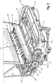
- FIG. 2 shows a perspective view of a chopping and distributing device 24, 30 of a combine harvester 1 according to Fig. 1 and the drive train of the distribution device 30.
- the chopping device 24 is arranged.
- the drive of the chopping device 24 takes place by means of a belt, not shown, which wraps around a coaxial with the chopper drum 25 arranged drive pulley 31.
- Adjacent and coaxial with the drive pulley 31 are arranged two driven pulleys 32 of different diameters which form a step drive 33.
- the step drive 33 is connected by a driven belt 36 with a countershaft 34.
- a tensioning device 35 maintains the belt tension of the driven belt 36.
- the counter stage 34 includes an output pulley 37 which is looped by a drive belt 38.
- the drive belt 38 also wraps around a drive pulley 39 which serves to drive the distribution device 30.
- the belt tension of the drive belt 38 is maintained by a tensioning system 49 which includes a tensioning roller 40 operable by an actuator.
- the actuator is designed as a hydraulically actuated lifting cylinder 41, which is single-acting.
- the piston rod of the lifting cylinder 41 actuates the tension roller 40 by a lever assembly 49 by the tension roller 40 is pressed against the drive belt 38 or spaced therefrom.
- a clutch 42 is in a switching state, so that the drive belt 38 can transmit a corresponding torque from the driven pulley 37 to the drive pulley 39.
- a first gear 44 which is designed as a bevel gear.
- a propeller shaft 46 which connects the first gear stage 44 to a second gear stage 47, is driven by the first gear stage 44.
- a perpendicular to the output shaft 43 extending drive shaft from (also not shown), which serves to drive a further rotor 45 of the distribution device 30.
- a brake 48 is disposed on the second gear 47.
- the operation of the drive train of the distribution device 30 will be explained in more detail below.
- the chopping device 24 is driven by the drive pulley 31, as described above. Coaxial with the drive pulley 31 is another, in the view according to Fig. 2 invisible drive disc arranged behind the drive pulley 31, which has a smaller outer diameter, whereby the chopping device 24 can be driven at different speeds. In particular, in the processing of corn as Erntegutart is worked with a lower drive speed to avoid damage to the chopping device 24.
- the step drive 33 is provided to translate the reduced drive speed of the chopper device 24 to the output speed required for a uniform distribution width for driving the distributor device 30.
- a variator can be provided in an advantageous embodiment, which simplifies the adaptation of the speed ratio and also designed continuously.
- the belt tension of the drive belt 38 wrapping the countershaft 34 and the drive pulley 39 is maintained by a tension system 50.
- the hydraulically actuable lift cylinder 41 is accordingly subjected to a hydraulic pressure to keep the belt tension of the drive belt 38 substantially constant.
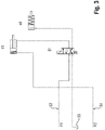
- the loading of the lifting cylinder 41 is effected by the connection to a hydraulic circuit of the combine harvester 1, which will be described below with reference to the in Fig. 3 illustrated section of a hydraulic circuit diagram of the combine 1 will be explained.
- the belt drive comprising the countershaft 34, the tensioning system 50, the drive pulley 39, and the drive belt 38 functions as a clutch 42 when the chopping device 24 is turned off.
- the necessary hydraulic pressure which keeps the lifting cylinder 41 against the force of the spring element in its 38 exciting position the drive belt, then is not on, so that the lifting cylinder 41 is retracted.
- the tension roller 40 is retracted by means of the lever arrangement 49, so that the drive belt 38 can not transmit any torque from the countershaft 34 to the drive belt pulley 39.
- the lifting cylinder 41 and the brake 48 are operatively connected via a valve 51, as in the circuit diagram in FIG Fig. 3 is shown.
- the designed as a 4/2-way valve valve 51 allows only two switching states, so that either the clutch by applying the lift cylinder 41 or the
- Brake 48 is active.
- the control of the valve 51 is carried out in dependence on the respective operating state of the chopping device 24.
- a first hydraulic pressure P1 of a first hydraulic circuit 52 of the combine harvester 1 which applies the brake 48 against the restoring force of a spring element with a hydraulic pressure, so that the brake 48 is active and the rotor 45 brakes.
- a second hydraulic pressure P2 of a second hydraulic circuit 54 through which the lifting cylinder 41 is extended, so that the lever assembly 49, the tension roller 40 from the drive belt 38 spaced, that is, the clutch is disengaged.
- the first hydraulic pressure P1 is for this purpose greater than the second hydraulic pressure P2.
- the valve 51 is correspondingly activated in order to activate the clutch 42 and at the same time to deactivate the brake 48.
- the brake 48 is depressurized by the switching of the valve 51, that is, hydraulic oil flows back into a tank 53, while the lifting cylinder 41 is acted on the ring side with the first hydraulic pressure P1, so that its piston against the piston side pending second hydraulic pressure P2 is inserted, whereby the clutch 42 is activated.
- the tensioning roller 40 is pressed against the drive belt 38 via the lever arrangement 49, as shown in FIG Fig. 2 seen.
Landscapes
- Life Sciences & Earth Sciences (AREA)
- Environmental Sciences (AREA)
- Harvester Elements (AREA)
Description
- Die vorliegende Erfindung betrifft einen Mähdrescher mit einer Häckselvorrichtung gemäß dem Oberbegriff des Anspruches 1.
- Aus der
DE 197 50 393 A1 ist ein mechanischer Antrieb für einen einer Reinigungseinrichtung nachgeordneten Spreuverteiler bekannt, welcher zwei oder mehr Gebläseeinheiten aufweist, die mechanisch angetrieben werden. Hierzu ist eine Keilriemenscheibe frei drehbar auf einer Welle angeordnet, die durch eine Kupplung kraftschlüssig mit der Keilriemenscheibe verbindbar ist. Der Antrieb der Keilriemenscheibe erfolgt über einen Antriebsstrang des Mähdreschers, ohne dies näher zu spezifizieren. Mit der Welle ist eine Gelenkwelle verbunden, die ein eingeleitetes Drehmoment auf eine Antriebswelle eines Kegelradgetriebes weiterleitet. Auf der Abtriebswelle des Kegelradgetriebes, welche eine der Gebläseeinheiten antreibt, sitzt eine Keilriemenscheibe, welche über einen Keilriemen die anderen Gebläseeinheiten antreibt. Diese Form des Antriebs für eine Verteilvorrichtung zeichnet sich durch eine hohe Komplexität aus. - Die
US2007/015556 A1 beschreibt einen Mähdrescher mit einer Häckselvorrichtung sowie einer dieser nachgeordneten Verteilvorrichtung. Die Verteilvorrichtung umfasst zwei Läufer. Die Verteilvorrichtung wird durch einen Antriebsstrang mechanisch angetrieben. - Aufgabe der vorliegenden Erfindung ist es, einen Mähdrescher der eingangs genannten Art weiterzubilden, dass sich dieser durch einen einfachen und energieeffizienten Antrieb seiner Verteilvorrichtung auszeichnet.
- Diese Aufgabe wird erfindungsgemäß durch die kennzeichnenden Merkmale des Anspruches 1 gelöst.
- Vorteilhafte Weiterbildungen sind Gegenstand der Unteransprüche.
- Gemäß dem Anspruch 1 wird vorgeschlagen, dass der Antriebsstrang der Verteilvorrichtung Folgendes umfasst:
- einen durch eine Kupplung schaltbaren Riementrieb, der über eine Abtriebswelle eine erste Getriebestufe antreibt,
- zumindest eine zweite Getriebestufe, die mit der ersten Getriebestufe durch eine Welle antriebsmäßig verbunden ist, wobei die jeweilige Getriebestufe zumindest eine Abtriebswelle zum Antreiben eines jeweiligen Läufer aufweist,
- sowie eine Bremsvorrichtung. Der mechanische Antrieb der Verteilvorrichtung weist gegenüber einem hydraulischen Antrieb den Vorteil auf, dass sich der mechanische Antrieb durch seine Drehzahlstabilität auszeichnet, woraus eine höhere Verteilstabilität resultiert. In Hinblick auf Sicherheitsanforderungen an den Betrieb von Verteilvorrichtungen, deren Läufer zumindest teilweise freiliegend angeordnet sind, ist es erforderlich, lange Nachlaufzeiten auf Grund der Massenträgheit zu vermeiden. Hierfür sind entsprechend eine Kupplung sowie eine Bremse in den Antriebsstrang integriert, die diesen einerseits auftrennen, um den Antriebsstrang der Verteilvorrichtung vom Mähdrescher zu entkoppeln, und andererseits die Läufer aktiv abbremsen. Auf diese Weise wird ein schnelles Abbremsen der Verteilvorrichtung beziehungsweise der Läufer erreicht.
- Bevorzugt kann der Riementrieb antriebsseitig an die Häckselvorrichtung gekoppelt sein. Diese Kopplung ist vor dem Hintergrund sinnvoll, dass die Häckselvorrichtung und die Verteilvorrichtung stets gemeinsam aktiv beziehungsweise inaktiv sind. Wird die Häckselvorrichtung abgeschaltet, weil auf Schwadablagebetrieb umgeschaltet wird, wird automatisch auch der Antrieb der Verteilvorrichtung stillgesetzt.
- Vorzugsweise kann der Riementrieb durch einen Stufenantrieb angetrieben sein. Durch das Umlegen des Riemens von einer Riemenscheibe größeren Durchmessers auf eine Riemenscheibe kleineren Durchmessers lässt sich auf einfache Weise eine Drehzahlverstellung realisieren. Dies ist von Bedeutung, wenn Erntegut, wie beispielsweise Mais, verarbeitet wird, welches auf Grund seiner Eigenschaften eine niedrigere Antriebsdrehzahl der Häckselvorrichtung erfordert, die Verteilbreite jedoch unverändert bleibt, so dass die Antriebsdrehzahl der Verteilvorrichtung gegenüber der der Häckselvorrichtung wesentlich höher sein muss. Durch den Stufenantrieb lässt sich eine entsprechende Übersetzung realisieren.
- Alternativ kann der Riementrieb durch einen Variator angetrieben sein. Der Variator erlaubt eine stufenlose Verstellung der Antriebsdrehzahl der Verteilvorrichtung, wodurch eine bessere Anpassung an sich ändernde Erntebedingungen erreichbar ist.
- Insbesondere kann der Riementrieb als Kupplung verwendbar sein. Der Antriebsstrang lässt sich durch den als Kupplung verwendeten Riementrieb unterbrechen, wenn das Häckselaggregat sowie die Verteilvorrichtung stillgesetzt werden sollen. Die Verwendung des Riementriebs als Kupplung stellt eine kostengünstige Lösung dar, da auf zusätzliche Bauteile im Antriebsstrang verzichtet werden kann.
- Hierzu weist der Riementrieb eine Spannrolle auf, die durch einen Aktor betätigbar ist. Die Spannrolle ist in Verbindung mit einem Stufengetriebe oder einem Variator zwingend erforderlich, um die Riemenspannung aufrecht zu erhalten. Entsprechend wird der Aktor angesteuert, um beispielsweise bei einem Umlegen des Riemens die notwendige Riemenspannung aufzubringen. Ist hingegen das Anhalten der Verteilvorrichtung und mit dieser das der freiliegenden Läufer erforderlich, weil der Mähdrescher beispielsweise auf eine andere Fruchtart umgestellt werden soll, so wird der Aktor entsprechend angesteuert, so dass die Riemenspannung nicht aufrechterhalten wird, indem die Kupplung ausgerückt wird.
- Vorteilhafterweise kann der Aktor als hydraulisch betätigbarer Hubzylinder ausgeführt sein. Insbesondere kann der Hubzylinder als einfach wirkender Hubzylinder ausgeführt sein. Hierbei weist der einfache wirkende Hubzylinder ein Federelement auf, welches kolbenseitig den Hubzylinder mit einer Kraft beaufschlagt, die der Rückstellung des Hubzylinders dient, wenn die Kupplung ausgerückt wird. Der einfach wirkende Hubzylinder kann über eine Hebelanordnung derart mit der Spannrolle verbunden sein, dass bei eingezogener Kolbenstange die Spannrolle gegen den Riemen presst wird, während bei ausgefahrener Kolbenstange die Spannrolle vom Riemen beabstandet wird. Bei in den Hubzylinder eingezogener Kolbenstange ist die Kupplung aktiv, während sie bei ausgefahrener Kolbenstange ausgerückt ist.
- Insbesondere kann der Hubzylinder an einen ersten und die Bremse an einen zweiten Hydraulikkreislauf am Mähdrescher gekoppelt sein, die mit unterschiedlichen hydraulischen Drücken arbeiten. Hierbei kann der Hubzylinder permanent mit dem hydraulischen Druck des zweiten Hydraulikkreislaufes und temporär mit dem hydraulischen Druck des ersten Hydraulikkreislaufes beaufschlagt werden, während die Bremse nur mit dem ersten Hydraulikkreislauf in Verbindung steht oder von diesem entkoppelt ist.
- In bevorzugter Weiterbildung können die Bremse und die Kupplung über ein gemeinsames Ventil schaltbar sein. Das Ventil ist vorzugsweise hydraulisch beaufschlagbar und ermöglicht das wahlweise Schalten von Bremse oder Kupplung. Hierzu kann das Ventil zwei Schaltstellungen aufweisen, so dass bei betätigter Kupplung die Bremse gelöst ist, während bei ausgeschalteter Kupplung die Bremse betätigt ist. Erreicht wird dies bei einem einfach wirkenden Hubzylinder dadurch, dass in einer ersten Schaltstellung, in der die Kupplung eingerückt und die Bremse inaktiv ist, der Hubzylinder ringseitig mit dem hydraulischen Druck des ersten Hydraulikkreislaufes, der höher ist als der des zweiten Hydraulikkreislaufs ist, beaufschlagt wird, so dass der Hubzylinder die Kupplung einrückt, um durch die Spannrolle die Riemenspannung aufrecht zu erhalten, während kolbenseitig der Hydraulikdruck des zweiten Hydraulikkreislaufes anliegt. Hingegen wird die Bremse in der ersten Schaltstellung des Ventils von dem ersten Hydraulikkreislauf entkoppelt, so dass diese nicht mit einem hydraulischen Druck beaufschlagt ist, so dass sich die Bremse in gelöster Position befindet. In der zweiten Schaltstellung des Ventils, in der die Kupplung ausgerückt ist und die Bremse aktiv ist, wird die Bremse mit dem hydraulischen Druck des ersten Hydraulikkreislaufes beaufschlagt. Der Hubzylinder wird in der zweiten Schaltstellung des Ventils ringseitig von dem ersten Hydraulikkreislauf getrennt, so dass durch den hydraulischen Druck des zweiten Hydraulikkreises, der kolbenseitig ansteht, sowie unterstützt von einer kolbenseitig anstehenden Federkraft, die Kolbenstange des Hubzylinders ausgefahren wird. Dadurch die Hebelanordnung derart betätigt, dass die Spannrolle von dem Riementrieb beabstandet wird, das heißt die Kupplung ausgerückt ist.
- Vorzugsweise kann die Bremse an einer der weiteren Getriebestufen angeordnet sein.
- Alternativ hierzu kann die Bremse in einer Riemenscheibe des Antriebsstranges angeordnet sein. Hierzu kann die Bremse als Trommelbremse ausgeführt sein.
- Dabei kann das Ventil in Abhängigkeit vom Betriebszustand der Häckselvorrichtung schaltbar sein. Das Ventil wird in Abhängigkeit vom Betriebszustand der Häckselvorrichtung geschaltet, wobei im laufenden Betrieb der Häckselvorrichtung das Ventil derart geschaltet ist, dass die Kupplung betätigt wird, um die Läufer der Verteilvorrichtung anzutreiben, während die Bremse in gelöster Stellung gehalten wird. Wird die Häckselvorrichtung abgeschaltet, so wird das Ventil derart angesteuert, dass die Bremse betätigt wird, während die Kupplung in gelöster Stellung gehalten wird, so dass der Riementrieb kein Antriebsmoment auf die Verteilvorrichtung übertragen kann. Vorzugsweis kann das Ventil als Schieberventil ausgeführt sein.
- Die vorliegende Erfindung wird nachstehend anhand eines in den Zeichnungen dargestellten Ausführungsbeispieles näher erläutert.
- Es zeigen:
- Fig. 1
- eine schematische Seitenansicht eines Mähdreschers;
- Fig.2
- eine perspektivische Ansicht einer Häcksel- und Verteilvorrichtung eines Mähdreschers gemäß
Fig. 1 ; - Fig. 3
- einen Ausschnitt aus einem Hydraulikschaltplan der Verteilvorrichtung.
-
Fig.1 zeigt die Seitenansicht einer als Mähdrescher 1 ausgeführten Erntemaschine mit einem an sich bekannten und daher hier nicht näher beschriebenen Dreschwerk 2 und einem diesem nachgeordneten Hordenschüttler 3 als Abscheideorgan 4. Unterhalb des Hordenschüttlers 3 befindet sich eine Reinigungseinrichtung 5, bestehend aus zwei übereinander angeordneten Sieben 6, 7 und einem Reinigungsgebläse 8. Die Erfindung ist aber ausdrücklich nicht auf derartig ausgeführte Mähdreschertypen beschränkt, sondern bezieht sich beispielsweise auch auf Mähdrescher mit Axialabscheiderotoren als Abscheideorgan sowie Mähdrescher mit axial angeordneter Dresch-Trennvorrichtung. - Im vorderen Bereich ist an dem Mähdrescher 1 ein Schneidwerk 10 angeordnet, mit dem das Erntegut 9 geschnitten und aufgenommen wird. Das Schneidwerk 10 führt das Erntegut 9 einem Schrägförderer 11 zu, der frontseitig am Mähdrescher 1 angeordnet ist. Der Schrägförderer 11 übergibt das Erntegut 9 an das im Maschinengehäuse 12 angeordnete Dreschwerk 2 zum Ausdrusch. Ein überwiegend aus Körnern bestehendes Korn-Spreu-Gemisch 13 wird am Dresch- und Abscheidekorb 14 des Dreschwerks 2 abgeschieden und gelangt über einen Vorbereitungsboden 15 zu der Reinigungseinrichtung 5, um die Körner 16 von den Nichtkornbestandteilen, das heißt von Halmteilen 17 und Spreuteilen 18 zu trennen.
- Im rückwärtigen Bereich ist dem Dreschwerk 2 eine rotierende Wendetrommel 19 zugeordnet, die den aus dem Dreschwerk 2 austretenden, im Wesentlichen aus ausgedroschenen Halmen bestehenden Gutstrom 20 annimmt und dem Hordenschüttler 3 zuführt, die den Gutstrom 20 in den rückwärtigen Bereich des Mähdreschers 1 fördert. Dabei werden die noch im Gutstrom 20 befindlichen Körner 16 sowie eventuell Kurzstroh 17 und Spreu 18 abgetrennt, indem sie durch den mit Sieböffnungen versehenen Hordenschüttler 3 hindurch auf einen Rücklaufboden 21 fallen. Der Rücklaufboden 21 transportiert Körner 16, Kurzstroh 17 und Spreu 18 zum Vorbereitungsboden 15.
- Die Körner 16, das Kurzstroh 17 und die Spreu 18 gelangen schließlich ebenfalls über den Vorbereitungsboden 15 in die Reinigungseinrichtung 5, in welcher die Körner 16 vom Kurzstroh 17 und von der Spreu 18 getrennt werden. Das Stroh 22 sowie ein bestimmter Prozentsatz an Verlustkörnern 23 wandern über den Hordenschüttler 3 zum hinteren Ende des Mähdreschers 1, wo sie einer Häckselvorrichtung 24 und einer dieser zugeordneten Verteilvorrichtung 30 zugeführt werden. Die Häckselvorrichtung 24 weist unter anderem eine rotierende Häckseltrommel 25 auf, die in einem Häckslergehäuse 26 gelagert ist. Die Häckseltrommel 25 ist mit beweglichen Messern 27 besetzt, die mit im Häckslergehäuse 26 fest angeordneten Gegenmessern 28 kämmen. Mit diesen Messern 27 und den Gegenmessern 28 wird das Stroh 22 zu Häckselgut zerkleinert und beschleunigt. Ein größtenteils aus Spreu bestehende Siebüberlauf, der nicht durch das Obersieb 6 hindurch fällt, gelangt über das Obersieb 6 in den hinteren Bereich des Mähdreschers 1 und kann ebenfalls der Häckselvorrichtung 24 zugeführt werden. Der aus der Häckselvorrichtung 24 austretende, im Wesentlichen aus gehäckseltem Stroh 22 und Spreu bestehende Gutstrom 29 wird an eine Verteilvorrichtung 30 weiterbefördert, die den Gutstrom 29 auf dem Feld verteilen.
- Die Darstellung in
Fig. 2 zeigt eine perspektivische Ansicht einer Häcksel- und Verteilvorrichtung 24, 30 eines Mähdreschers 1 gemäßFig. 1 sowie des Antriebsstranges der Verteilvorrichtung 30. In dem Maschinengehäuse 12 ist, wie weiter oben bereits ausgeführt, die Häckselvorrichtung 24 angeordnet. Der Antrieb der Häckselvorrichtung 24 erfolgt mittels eines nicht dargestellten Riemens, der eine koaxial zu der Häckseltrommel 25 angeordnete Antriebsriemenscheibe 31 umschlingt. Benachbart und koaxial zu der Antriebsriemenscheibe 31 sind zwei Abtriebsriemenscheiben 32 verschiedenen Durchmessers angeordnet, die einen Stufenantrieb 33 bilden. Der Stufenantrieb 33 ist durch einen Abtriebsriemen 36 mit einer Vorgelegestufe 34 verbunden. Eine Spannvorrichtung 35 hält die Riemenspannung des Abtriebsriemens 36 aufrecht. Die Vorgelegestufe 34 umfasst eine Abtriebsriemenscheibe 37, die von einem Antriebsriemen 38 umschlungen ist. Der Antriebsriemen 38 umschlingt außerdem eine Antriebsriemenscheibe 39, die dem Antrieb der Verteilvorrichtung 30 dient. Die Riemenspannung des Antriebsriemens 38 wird durch ein Spannsystem 49 aufrechterhalten, das eine durch einen Aktor betätigbare eine Spannrolle 40 umfasst. Der Aktor ist als hydraulisch betätigbarer Hubzylinder 41 ausgeführt, der einfach wirkend ist. Die Kolbenstange des Hubzylinder 41 betätigt die Spannrolle 40 durch eine Hebelanordnung 49, indem die Spannrolle 40 gegen den Antriebsriemen 38 gepresst oder zu diesem beabstandet wird. Im vorliegenden Ausführungsbeispiel befindet sich eine Kupplung 42 in einem Schaltzustand, so dass der Antriebsriemen 38 ein entsprechendes Drehmoment von der Abtriebsriemenscheibe 37 auf die Antriebsriemenscheibe 39 übertragen kann. - Von der Antriebsriemenscheibe 39 geht eine Abtriebswelle 43 ab, die in einer ersten Getriebestufe 44, die als Kegelradgetriebe ausgeführt ist, mündet. Von der ersten Getriebestufe 44 geht eine sich senkrecht zur Abtriebswelle 43 erstreckende Antriebswelle ab (nicht dargestellt), die dem Antrieb eines Läufers 45 der Verteilvorrichtung 30 dient. Weiterhin geht von der ersten Getriebestufe 44 eine Gelenkwelle 46 ab, die die erste Getriebestufe 44 antriebsmäßig mit einer zweiten Getriebestufe 47 verbindet. Auch von der zweiten Getriebestufe 47 geht eine sich senkrecht zur Abtriebswelle 43 erstreckende Antriebswelle ab (ebenfalls nicht dargestellt), die dem Antrieb eines weiteren Läufers 45 der Verteilvorrichtung 30 dient. Koaxial zur Abtriebswelle 43 ist an der zweiten Getriebestufe 47 eine Bremse 48 angeordnet.
- Nachstehend wird die Funktionsweise des Antriebsstranges der Verteilvorrichtung 30 näher erläutert. Die Häckselvorrichtung 24 wird, wie weiter oben beschrieben wurde, durch die Antriebsriemenscheibe 31 angetrieben. Koaxial zu der Antriebsscheibe 31 ist eine weitere, in der Ansicht gemäß
Fig. 2 nicht sichtbare Antriebsscheibe hinter der Antriebsscheibe 31 angeordnet, die einen kleineren Außendurchmesser aufweist, wodurch die Häckselvorrichtung 24 mit unterschiedlichen Drehzahlen antreibbar ist. Insbesondere bei der Verarbeitung von Mais als Erntegutart wird mit einer geringeren Antriebsdrehzahl gearbeitet, um Beschädigungen der Häckselvorrichtung 24 zu vermeiden. Um diese Drehzahlreduzierung bei einem mechanischen Antrieb der Verteilvorrichtung 30 zu kompensieren, ist der Stufenantrieb 33 vorgesehen, um die reduzierte Antriebsdrehzahl der Häckselvorrichtung 24 auf die für eine geleichmäßige Verteilbreite erforderliche Abtriebsdrehzahl für den Antrieb der Verteilvorrichtung 30 zu übersetzten. Als Alternative zum Stufenantrieb 33 kann in vorteilhafter Ausgestaltung auch ein Variator vorgesehen sein, der die Anpassung der Drehzahlübersetzung vereinfacht und zudem stufenlos gestaltet. - Die Riemenspannung des das Vorgelege 34 und die Antriebsriemenscheibe 39 umschlingenden Antriebsriemens 38 wird durch ein Spannsystem 50 aufrechterhalten. Der hydraulisch betätigbare Hubzylinder 41 wird entsprechend mit einem Hydraulikdruck beaufschlagt, um die Riemenspannung des Antriebsriemens 38 im Wesentlichen konstant zu halten. Die Beaufschlagung des Hubzylinders 41 erfolgt durch die Anbindung an einen Hydraulikkreislauf des Mähdreschers 1, was weiter unten anhand des in
Fig. 3 dargestellten Ausschnittes aus einem Hydraulikschaltplan des Mähdreschers 1 erläutert wird. - Der Riementrieb, umfassend das Vorgelege 34, das Spannsystem 50, die Antriebsriemenscheibe 39 sowie den Antriebsriemen 38, fungiert als Kupplung 42, wenn die Häckselvorrichtung 24 abgeschaltet wird. Der notwendige Hydraulikdruck, der den Hubzylinder 41 entgegen der Kraft des Federelementes in seiner den Antriebsriemen 38 spannenden Stellung hält, steht dann nicht an, so dass der Hubzylinder 41 eingezogen wird. Die Spannrolle 40 wird mittels der Hebelanordnung 49 zurückgenommen, so dass der Antriebsriemen 38 kein Drehmoment vom Vorgelege 34 auf die Antriebsriemenscheibe 39 übertragen kann. Um im gleichen Augenblick die Bremse 48 an der zweiten Getriebestufe 47 zu aktivieren, damit beide Läufer 45 aktiv abgebremst werden, sind der Hubzylinder 41 und die Bremse 48 über ein Ventil 51 wirkverbunden, wie in dem Schaltplanauszug in
Fig. 3 dargestellt ist. - Das als 4/2-Wege-Ventil ausgeführte Ventil 51 erlaubt lediglich zwei Schaltzustände, so dass entweder die Kupplung durch Beaufschlagung des Hubzylinders 41 oder die
- Bremse 48 aktiv ist. Die Ansteuerung des Ventils 51 erfolgt in Abhängigkeit von dem jeweiligen Betriebszustand der Häckselvorrichtung 24. Bei nicht in Betrieb befindlicher Häckselvorrichtung 24, wie in dem Schaltplanausschnitt gemäß
Fig. 3 dargestellt, steht an dem Ventil 51 ein erster Hydraulikdruck P1 eines ersten Hydraulikkreislaufes 52 des Mähdreschers 1 an, der die Bremse 48 entgegen der Rückstellkraft eines Federelementes mit einem hydraulischen Druck beaufschlagt, so dass die Bremse 48 aktiv ist und die Läufer 45 bremst. In dieser Schaltstellung des Ventils 51 steht an dem einfach wirkenden Hubzylinder 41 kolbenseitig ein zweiter Hydraulikdruck P2 eines zweiten Hydraulikkreislaufes 54 an, durch den der Hubzylinder 41 ausgefahren wird, so dass die Hebelanordnung 49 die Spannrolle 40 von dem Antriebsriemen 38 beabstandet, das heißt die Kupplung ausgerückt ist. Der erste Hydraulikdruck P1 ist hierzu größer als der zweite Hydraulikdruck P2. - Wird die Häckselvorrichtung 24 eingeschaltet, so wird das Ventil 51 entsprechend angesteuert, um die Kupplung 42 zu aktivieren und zugleich die Bremse 48 zu deaktivieren. Hierzu wird durch das Schalten des Ventils 51 die Bremse 48 drucklos geschaltet, das heißt, dass Hydrauliköl fließt zurück in einen Tank 53, während der Hubzylinder 41 ringseitig mit dem ersten Hydraulikdruck P1 beaufschlagt wird, so dass dessen Kolben entgegen des kolbenseitig anstehenden zweiten Hydraulikdrucks P2 eingeschoben wird, wodurch die Kupplung 42 aktiviert wird. Hierzu wird über die Hebelanordnung 49 die Spannrolle 40 gegen den Antriebsriemen 38 gepresst, wie aus der Darstellung in
Fig. 2 ersichtlich.Bezugszeichenliste 1 Mähdrescher 32 Abtriebsriemenscheibe 2 Dreschwerk 33 Stufenantrieb 3 Hordenschüttler 34 Vorgelegestufe 4 Abscheideorgan 35 Spannvorrichtung 5 Reinigungseinrichtung 36 Abtriebsriemen 6 Sieb 37 Abtriebsriemenscheibe 7 Sieb 38 Antriebsriemen 8 Reinigungsgebläse 39 Antriebsriemenscheibe 9 Erntegut 40 Spannrolle 10 Schneidwerk 41 Hubzylinder 11 Schrägförderer 42 Kupplung 12 Maschinengehäuse 43 Abtriebswelle 13 Korn-Spreu-Gemisch 44 Erste Getriebestufe 14 Abscheidekorb 45 Läufer 15 Vorbereitungsboden 46 Gelenkwelle 16 Korn 47 Zweite Getriebestufe 17 Halmteil 48 Bremse 18 Spreuteil 49 Hebelanordnung 19 Wendetrommel 50 Spannsystem 20 Gutstrom 51 Ventil 21 Rücklaufboden 52 Erster Hydraulikkreislauf 22 Stroh 53 Tank 23 Verlustkörner 54 Zweiter Hydraulikkreislauf 24 Häckselvorrichtung P1 Erster Hydraulikdruck 25 Häckseltrommel P2 Zweiter Hydraulikdruck 26 Häckslergehäuse 27 Messer 28 Gegenmesser 29 Gutstrom 30 Verteilvorrichtung 31 Antriebsriemenscheibe
Claims (12)
- Mähdrescher (1) mit einer Häckselvorrichtung (24) und einer dieser nachgeordneten, durch einen Antriebsstrang mechanisch angetriebenen, mindestens zwei Läufer (45) aufweisenden Verteilvorrichtung (30), dadurch gekennzeichnet, dass der Antriebsstrang der Verteilvorrichtung (30) Folgendes umfasst:- einen schaltbaren Riementrieb (37,38,39), der über eine Abtriebswelle (43) eine erste Getriebestufe (44) antreibt,- zumindest eine zweite Getriebestufe (47), die mit der ersten Getriebestufe (44) durch eine Welle (46) antriebsmäßig verbunden ist, wobei die jeweilige Getriebestufe (44, 47) zumindest eine Abtriebswelle zum Antreiben des jeweiligen Läufers (45) aufweist,- sowie eine Bremsvorrichtung (48).
- Mähdrescher (1) nach Anspruch 1, dadurch gekennzeichnet, dass der Riementrieb (37,38,39) antriebsseitig an die Häckselvorrichtung (24) gekoppelt ist.
- Mähdrescher (1) nach einem der Ansprüche 1 oder 2, dadurch gekennzeichnet, dass der Riementrieb (37,38,39) durch einen Stufenantrieb (34) angetrieben ist.
- Mähdrescher (1) nach einem der Ansprüche 1 oder 2, dadurch gekennzeichnet, dass der Riementrieb (37,38,39) durch einen Variator angetrieben ist.
- Mähdrescher nach einem der Ansprüche 1 bis 4, dadurch gekennzeichnet, dass der Riementrieb (37,38,39) als Kupplung (42) verwendet wird.
- Mähdrescher (1) nach einem der Ansprüche 1 bis 5, dadurch gekennzeichnet, dass der Riementrieb (37,38,39) eine Spannrolle (40) umfasst, die durch einen Aktor (41) betätigbar ist.
- Mähdrescher (1) nach Anspruch 6, dadurch gekennzeichnet, dass der Aktor als hydraulisch betätigbarer Hubzylinder (41) ausgeführt ist.
- Mähdrescher (1) nach Anspruch 7, dadurch gekennzeichnet, dass der Hubzylinder (41) an einen ersten Hydraulikkreislauf (52) und die Bremse (48) an einen zweiten Hydraulikkreislauf (54) am Mähdreschers (1) gekoppelt sind, die mit unterschiedlichen Hydraulikdrücken (P1, P2) arbeiten.
- Mähdrescher (1) nach einem der Ansprüche 1 bis 8, dadurch gekennzeichnet, dass die Bremse (48) an einer der weiteren Getriebestufen (47) angeordnet ist.
- Mähdrescher (1) nach einem der Ansprüche 1 bis 8, dadurch gekennzeichnet, dass die Bremse (48) in einer Riemenscheibe (31,32,37,39) des Antriebsstranges angeordnet ist.
- Mähdrescher (1) nach einem der Ansprüche 1 bis 10, dadurch gekennzeichnet, dass die Bremse (48) und die Kupplung (42) über ein gemeinsames Ventil (51) schaltbar sind.
- Mähdrescher (1) nach Anspruch 11, dadurch gekennzeichnet, dass das Ventil (51) in Abhängigkeit vom Betriebszustand der Häckselvorrichtung (24) schaltbar ist.
Applications Claiming Priority (1)
| Application Number | Priority Date | Filing Date | Title |
|---|---|---|---|
| DE102013108923.2A DE102013108923A1 (de) | 2013-08-19 | 2013-08-19 | Mähdrescher mit einer Häckselvorrichtung |
Publications (3)
| Publication Number | Publication Date |
|---|---|
| EP2839729A1 EP2839729A1 (de) | 2015-02-25 |
| EP2839729B1 true EP2839729B1 (de) | 2016-05-18 |
| EP2839729B2 EP2839729B2 (de) | 2019-05-22 |
Family
ID=50735958
Family Applications (1)
| Application Number | Title | Priority Date | Filing Date |
|---|---|---|---|
| EP14169203.8A Active EP2839729B2 (de) | 2013-08-19 | 2014-05-21 | Mähdrescher mit einer Häckselvorrichtung |
Country Status (4)
| Country | Link |
|---|---|
| US (1) | US9313949B2 (de) |
| EP (1) | EP2839729B2 (de) |
| DE (1) | DE102013108923A1 (de) |
| RU (1) | RU2653078C2 (de) |
Cited By (1)
| Publication number | Priority date | Publication date | Assignee | Title |
|---|---|---|---|---|
| EP3443833A1 (de) | 2017-08-18 | 2019-02-20 | CLAAS Selbstfahrende Erntemaschinen GmbH | Antriebsstrang zum antreiben eines arbeitsaggregates einer selbstfahrenden erntemaschine |
Families Citing this family (6)
| Publication number | Priority date | Publication date | Assignee | Title |
|---|---|---|---|---|
| EP3017682B1 (de) * | 2014-08-14 | 2019-03-06 | Dean Mayerle | Antriebssystem für einen strohhäcksler eines mähdreschers |
| CA2991256C (en) | 2015-07-14 | 2021-12-07 | Dean Mayerle | Weed seed destruction formed as a common unit with straw spreader |
| AU2017228663B2 (en) * | 2015-07-14 | 2018-08-30 | Tritana Intellectual Property Ltd. | Weed seed destruction |
| US10375885B2 (en) * | 2015-09-17 | 2019-08-13 | Deere & Company | System for chopping and spreading residue |
| US12114609B2 (en) | 2021-07-21 | 2024-10-15 | Cnh Industrial America Llc | Integrated weed seed mill and chopper for combine harvester |
| JP7851271B2 (ja) * | 2023-06-28 | 2026-04-24 | 株式会社クボタ | コンバイン |
Citations (8)
| Publication number | Priority date | Publication date | Assignee | Title |
|---|---|---|---|---|
| DE3544157C1 (de) | 1985-08-20 | 1987-07-30 | Biso Bitter Gmbh & Co Kg | Vorrichtung fuer Maehdrescher zum Verteilen der Spreu |
| US4696381A (en) | 1985-09-27 | 1987-09-29 | Johnson Sr Lee A | Clutch and brake apparatus |
| US4735216A (en) | 1982-08-02 | 1988-04-05 | Gehl Company | Straw chopper and spreader assembly |
| EP0408156B1 (de) | 1987-05-15 | 1994-08-10 | Deere & Company | Antriebssystem für Mähdrescher |
| DE4344649A1 (de) | 1993-12-24 | 1995-06-29 | Mezoegaz Gepgyar Szolgalt Vall | Kombinierter Riemenschaltmechanismus, insbesondere zum Antrieb des Strohhäckslers von Mähdreschern |
| EP1400162A1 (de) | 2002-09-19 | 2004-03-24 | Deere & Company | Sicherheitseinrichtung einer Erntemaschine |
| US20070015556A1 (en) | 2005-07-15 | 2007-01-18 | Deere & Company, A Delaware Corporation | Wide-spread impeller spreader for harvesting combine |
| DE102006045789A1 (de) | 2006-09-26 | 2008-06-26 | Claas Selbstfahrende Erntemaschinen Gmbh | Antriebseinrichtung für Mähdrescher |
Family Cites Families (12)
| Publication number | Priority date | Publication date | Assignee | Title |
|---|---|---|---|---|
| US3186460A (en) * | 1961-07-20 | 1965-06-01 | Frederick Joseph | Straw chopping apparatus |
| US4292795A (en) * | 1979-11-19 | 1981-10-06 | Linn Orville J | Straw and chaff chopper and spreader |
| US4526180A (en) * | 1982-08-02 | 1985-07-02 | Keith Industries Incorporated | Straw chopper and spreader assembly |
| SU1181581A1 (ru) * | 1984-01-13 | 1985-09-30 | Головное специализированное конструкторское бюро по комплексам зерноуборочных машин Производственного объединения "Ростсельмаш" | Приспособление к зерноуборочному комбайну дл уборки незерновой части урожа |
| US4591102A (en) * | 1984-08-20 | 1986-05-27 | Clarke James A | Chaff spreader for combine harvester |
| DE3704755A1 (de) * | 1987-02-16 | 1988-08-25 | Claas Ohg | Maehdrescher mit einer einrichtung zum verteilen des korn-spreu-gemisches |
| DE19750393A1 (de) | 1997-11-14 | 1998-04-30 | Jakobi Wilhelm Dipl Ing Fh | Mähdrescher-Spreuverteiler mit Radial-Sauggebläsen |
| DE19908111C1 (de) * | 1999-02-25 | 2000-07-27 | Claas Selbstfahr Erntemasch | Mähdrescher mit Breitverteileraustrag für gehäckseltes Stroh-Spreu-Gemisch |
| CA2274288A1 (en) * | 1999-06-09 | 2000-12-09 | Mcleod Harvest Inc. | Method and apparatus for harvesting crops |
| RU2219699C2 (ru) * | 2001-09-19 | 2003-12-27 | Открытое акционерное общество Алтайский научно-исследовательский институт технологии машиностроения | Измельчитель соломы для зерноуборочного комбайна |
| US7993188B2 (en) * | 2009-06-09 | 2011-08-09 | Deere & Company | Variable rate diverter for a crop residue collecting device carried by a combine harvester |
| DE102009042002A1 (de) * | 2009-09-21 | 2011-03-24 | Claas Selbstfahrende Erntemaschinen Gmbh | Verfahren und Verteilen eines Gutstromes auf einem Feld sowie Häcksel- und Verteilvorrichtung |
-
2013
- 2013-08-19 DE DE102013108923.2A patent/DE102013108923A1/de not_active Withdrawn
-
2014
- 2014-05-21 EP EP14169203.8A patent/EP2839729B2/de active Active
- 2014-08-13 US US14/458,626 patent/US9313949B2/en not_active Expired - Fee Related
- 2014-08-14 RU RU2014133393A patent/RU2653078C2/ru active
Patent Citations (8)
| Publication number | Priority date | Publication date | Assignee | Title |
|---|---|---|---|---|
| US4735216A (en) | 1982-08-02 | 1988-04-05 | Gehl Company | Straw chopper and spreader assembly |
| DE3544157C1 (de) | 1985-08-20 | 1987-07-30 | Biso Bitter Gmbh & Co Kg | Vorrichtung fuer Maehdrescher zum Verteilen der Spreu |
| US4696381A (en) | 1985-09-27 | 1987-09-29 | Johnson Sr Lee A | Clutch and brake apparatus |
| EP0408156B1 (de) | 1987-05-15 | 1994-08-10 | Deere & Company | Antriebssystem für Mähdrescher |
| DE4344649A1 (de) | 1993-12-24 | 1995-06-29 | Mezoegaz Gepgyar Szolgalt Vall | Kombinierter Riemenschaltmechanismus, insbesondere zum Antrieb des Strohhäckslers von Mähdreschern |
| EP1400162A1 (de) | 2002-09-19 | 2004-03-24 | Deere & Company | Sicherheitseinrichtung einer Erntemaschine |
| US20070015556A1 (en) | 2005-07-15 | 2007-01-18 | Deere & Company, A Delaware Corporation | Wide-spread impeller spreader for harvesting combine |
| DE102006045789A1 (de) | 2006-09-26 | 2008-06-26 | Claas Selbstfahrende Erntemaschinen Gmbh | Antriebseinrichtung für Mähdrescher |
Non-Patent Citations (1)
| Title |
|---|
| "Safe Use of Combine Harvesters", HEALTH AND SAFETY EXECUTIVE INFORMATION SHEET NO. 6, 2012, Druckvermerk, pages 1 - 3, XP055354206 |
Cited By (3)
| Publication number | Priority date | Publication date | Assignee | Title |
|---|---|---|---|---|
| EP3443833A1 (de) | 2017-08-18 | 2019-02-20 | CLAAS Selbstfahrende Erntemaschinen GmbH | Antriebsstrang zum antreiben eines arbeitsaggregates einer selbstfahrenden erntemaschine |
| DE102017118858A1 (de) | 2017-08-18 | 2019-02-21 | Claas Selbstfahrende Erntemaschinen Gmbh | Antriebsstrang zum Antreiben eines Arbeitsaggregates einer selbstfahrenden Erntemaschine |
| US10830287B2 (en) | 2017-08-18 | 2020-11-10 | Claas Selbstfahrende Erntemaschinen Gmbh | Drive train for driving a working unit of a self-propelled harvester |
Also Published As
| Publication number | Publication date |
|---|---|
| RU2653078C2 (ru) | 2018-05-07 |
| RU2014133393A (ru) | 2016-03-10 |
| US20150050969A1 (en) | 2015-02-19 |
| US9313949B2 (en) | 2016-04-19 |
| DE102013108923A1 (de) | 2015-02-19 |
| EP2839729B2 (de) | 2019-05-22 |
| EP2839729A1 (de) | 2015-02-25 |
Similar Documents
| Publication | Publication Date | Title |
|---|---|---|
| EP2839729B1 (de) | Mähdrescher mit einer Häckselvorrichtung | |
| EP2837280B1 (de) | Mähdrescher mit einer Häckselvorrichtung | |
| EP2810549B1 (de) | Mähdrescher | |
| EP1046334B1 (de) | Antriebseinrichtung der Förder- und/oder Gutbearbeitungsvorrichtung einer Erntemaschine | |
| EP2789222B1 (de) | Als Riementriebe ausgebildetes Antriebssystem eines selbstfahrenden Mähdreschers | |
| EP3443833B1 (de) | Selbstfahrende erntemaschine mit einem antriebsstrang zum antreiben eines arbeitsaggregates | |
| DE102015206845B4 (de) | Schneidwerk zur Ganzpflanzenernte | |
| EP2952087B1 (de) | Antriebssystem für eine selbstfahrende Erntemaschine | |
| EP2676538A1 (de) | Tangentialdreschwerk mit einer Fördertrommel und einer Dresch- oder Abscheidetrommel | |
| EP2687079A2 (de) | Reihenunabhängig arbeitendes Vorsatzgerät zum Ernten von stängeligem Erntegut | |
| EP0727135B1 (de) | Mähdrescher | |
| DE102012101807A1 (de) | Selbstfahrende Erntemaschine | |
| EP3000301B1 (de) | Selbstfahrender mähdrescher | |
| EP2805602B1 (de) | Mähdrescher | |
| EP4470358A1 (de) | Selbstfahrender mähdrescher mit einem vorsatzgerät | |
| EP3338527B1 (de) | Mähdrescher | |
| BE1022970B1 (de) | Verstellanordnung zur Verstellung des Arbeitsspaltes eines Korbes einer Dresch- und/oder Trenneinrichtung | |
| EP4305947A1 (de) | Mähdrescher | |
| DE2231511A1 (de) | Rotor-antriebsvorrichtung fuer maehdrescher der axialflussbauart | |
| EP2574227B1 (de) | Selbstfahrende Erntemaschine | |
| DE102011088543A1 (de) | Mähdrescher mit einer zwischen der Drescheinrichtung und der Reinigung angeordneten Nachdrescheinrichtung | |
| DE102023132967A1 (de) | Mähdrescher | |
| DE102021131106A1 (de) | Adaptereinheit zur Ankopplung eines Vorsatzgerätes an eine selbstfahrende Erntemaschine | |
| DE102021131109A1 (de) | Adaptereinheit zur Ankopplung eines Vorsatzgerätes an eine selbstfahrende Erntemaschine | |
| DE102021131107A1 (de) | Selbstfahrende Erntemaschine |
Legal Events
| Date | Code | Title | Description |
|---|---|---|---|
| PUAI | Public reference made under article 153(3) epc to a published international application that has entered the european phase |
Free format text: ORIGINAL CODE: 0009012 |
|
| 17P | Request for examination filed |
Effective date: 20140521 |
|
| AK | Designated contracting states |
Kind code of ref document: A1 Designated state(s): AL AT BE BG CH CY CZ DE DK EE ES FI FR GB GR HR HU IE IS IT LI LT LU LV MC MK MT NL NO PL PT RO RS SE SI SK SM TR |
|
| AX | Request for extension of the european patent |
Extension state: BA ME |
|
| R17P | Request for examination filed (corrected) |
Effective date: 20150825 |
|
| RBV | Designated contracting states (corrected) |
Designated state(s): AL AT BE BG CH CY CZ DE DK EE ES FI FR GB GR HR HU IE IS IT LI LT LU LV MC MK MT NL NO PL PT RO RS SE SI SK SM TR |
|
| GRAP | Despatch of communication of intention to grant a patent |
Free format text: ORIGINAL CODE: EPIDOSNIGR1 |
|
| INTG | Intention to grant announced |
Effective date: 20160302 |
|
| GRAS | Grant fee paid |
Free format text: ORIGINAL CODE: EPIDOSNIGR3 |
|
| GRAA | (expected) grant |
Free format text: ORIGINAL CODE: 0009210 |
|
| AK | Designated contracting states |
Kind code of ref document: B1 Designated state(s): AL AT BE BG CH CY CZ DE DK EE ES FI FR GB GR HR HU IE IS IT LI LT LU LV MC MK MT NL NO PL PT RO RS SE SI SK SM TR |
|
| REG | Reference to a national code |
Ref country code: GB Ref legal event code: FG4D Free format text: NOT ENGLISH |
|
| REG | Reference to a national code |
Ref country code: CH Ref legal event code: EP |
|
| REG | Reference to a national code |
Ref country code: IE Ref legal event code: FG4D Free format text: LANGUAGE OF EP DOCUMENT: GERMAN Ref country code: AT Ref legal event code: REF Ref document number: 799547 Country of ref document: AT Kind code of ref document: T Effective date: 20160615 |
|
| REG | Reference to a national code |
Ref country code: DE Ref legal event code: R096 Ref document number: 502014000788 Country of ref document: DE |
|
| REG | Reference to a national code |
Ref country code: NL Ref legal event code: MP Effective date: 20160518 |
|
| REG | Reference to a national code |
Ref country code: LT Ref legal event code: MG4D |
|
| PG25 | Lapsed in a contracting state [announced via postgrant information from national office to epo] |
Ref country code: LT Free format text: LAPSE BECAUSE OF FAILURE TO SUBMIT A TRANSLATION OF THE DESCRIPTION OR TO PAY THE FEE WITHIN THE PRESCRIBED TIME-LIMIT Effective date: 20160518 Ref country code: NO Free format text: LAPSE BECAUSE OF FAILURE TO SUBMIT A TRANSLATION OF THE DESCRIPTION OR TO PAY THE FEE WITHIN THE PRESCRIBED TIME-LIMIT Effective date: 20160818 Ref country code: FI Free format text: LAPSE BECAUSE OF FAILURE TO SUBMIT A TRANSLATION OF THE DESCRIPTION OR TO PAY THE FEE WITHIN THE PRESCRIBED TIME-LIMIT Effective date: 20160518 Ref country code: NL Free format text: LAPSE BECAUSE OF FAILURE TO SUBMIT A TRANSLATION OF THE DESCRIPTION OR TO PAY THE FEE WITHIN THE PRESCRIBED TIME-LIMIT Effective date: 20160518 |
|
| PG25 | Lapsed in a contracting state [announced via postgrant information from national office to epo] |
Ref country code: GR Free format text: LAPSE BECAUSE OF FAILURE TO SUBMIT A TRANSLATION OF THE DESCRIPTION OR TO PAY THE FEE WITHIN THE PRESCRIBED TIME-LIMIT Effective date: 20160819 Ref country code: LV Free format text: LAPSE BECAUSE OF FAILURE TO SUBMIT A TRANSLATION OF THE DESCRIPTION OR TO PAY THE FEE WITHIN THE PRESCRIBED TIME-LIMIT Effective date: 20160518 Ref country code: HR Free format text: LAPSE BECAUSE OF FAILURE TO SUBMIT A TRANSLATION OF THE DESCRIPTION OR TO PAY THE FEE WITHIN THE PRESCRIBED TIME-LIMIT Effective date: 20160518 Ref country code: RS Free format text: LAPSE BECAUSE OF FAILURE TO SUBMIT A TRANSLATION OF THE DESCRIPTION OR TO PAY THE FEE WITHIN THE PRESCRIBED TIME-LIMIT Effective date: 20160518 Ref country code: SE Free format text: LAPSE BECAUSE OF FAILURE TO SUBMIT A TRANSLATION OF THE DESCRIPTION OR TO PAY THE FEE WITHIN THE PRESCRIBED TIME-LIMIT Effective date: 20160518 Ref country code: ES Free format text: LAPSE BECAUSE OF FAILURE TO SUBMIT A TRANSLATION OF THE DESCRIPTION OR TO PAY THE FEE WITHIN THE PRESCRIBED TIME-LIMIT Effective date: 20160518 Ref country code: PT Free format text: LAPSE BECAUSE OF FAILURE TO SUBMIT A TRANSLATION OF THE DESCRIPTION OR TO PAY THE FEE WITHIN THE PRESCRIBED TIME-LIMIT Effective date: 20160919 |
|
| RAP2 | Party data changed (patent owner data changed or rights of a patent transferred) |
Owner name: CLAAS SELBSTFAHRENDE ERNTEMASCHINEN GMBH |
|
| PG25 | Lapsed in a contracting state [announced via postgrant information from national office to epo] |
Ref country code: IT Free format text: LAPSE BECAUSE OF FAILURE TO SUBMIT A TRANSLATION OF THE DESCRIPTION OR TO PAY THE FEE WITHIN THE PRESCRIBED TIME-LIMIT Effective date: 20160518 |
|
| PG25 | Lapsed in a contracting state [announced via postgrant information from national office to epo] |
Ref country code: EE Free format text: LAPSE BECAUSE OF FAILURE TO SUBMIT A TRANSLATION OF THE DESCRIPTION OR TO PAY THE FEE WITHIN THE PRESCRIBED TIME-LIMIT Effective date: 20160518 Ref country code: RO Free format text: LAPSE BECAUSE OF FAILURE TO SUBMIT A TRANSLATION OF THE DESCRIPTION OR TO PAY THE FEE WITHIN THE PRESCRIBED TIME-LIMIT Effective date: 20160518 Ref country code: SK Free format text: LAPSE BECAUSE OF FAILURE TO SUBMIT A TRANSLATION OF THE DESCRIPTION OR TO PAY THE FEE WITHIN THE PRESCRIBED TIME-LIMIT Effective date: 20160518 Ref country code: DK Free format text: LAPSE BECAUSE OF FAILURE TO SUBMIT A TRANSLATION OF THE DESCRIPTION OR TO PAY THE FEE WITHIN THE PRESCRIBED TIME-LIMIT Effective date: 20160518 Ref country code: CZ Free format text: LAPSE BECAUSE OF FAILURE TO SUBMIT A TRANSLATION OF THE DESCRIPTION OR TO PAY THE FEE WITHIN THE PRESCRIBED TIME-LIMIT Effective date: 20160518 |
|
| REG | Reference to a national code |
Ref country code: DE Ref legal event code: R026 Ref document number: 502014000788 Country of ref document: DE |
|
| PLBI | Opposition filed |
Free format text: ORIGINAL CODE: 0009260 |
|
| REG | Reference to a national code |
Ref country code: IE Ref legal event code: MM4A |
|
| PG25 | Lapsed in a contracting state [announced via postgrant information from national office to epo] |
Ref country code: SM Free format text: LAPSE BECAUSE OF FAILURE TO SUBMIT A TRANSLATION OF THE DESCRIPTION OR TO PAY THE FEE WITHIN THE PRESCRIBED TIME-LIMIT Effective date: 20160518 Ref country code: PL Free format text: LAPSE BECAUSE OF FAILURE TO SUBMIT A TRANSLATION OF THE DESCRIPTION OR TO PAY THE FEE WITHIN THE PRESCRIBED TIME-LIMIT Effective date: 20160518 |
|
| 26 | Opposition filed |
Opponent name: DEERE & COMPANY/JOHN DEERE GMBH & CO. KG Effective date: 20170215 |
|
| PLAX | Notice of opposition and request to file observation + time limit sent |
Free format text: ORIGINAL CODE: EPIDOSNOBS2 |
|
| PG25 | Lapsed in a contracting state [announced via postgrant information from national office to epo] |
Ref country code: MC Free format text: LAPSE BECAUSE OF FAILURE TO SUBMIT A TRANSLATION OF THE DESCRIPTION OR TO PAY THE FEE WITHIN THE PRESCRIBED TIME-LIMIT Effective date: 20160518 |
|
| REG | Reference to a national code |
Ref country code: FR Ref legal event code: ST Effective date: 20170313 |
|
| PG25 | Lapsed in a contracting state [announced via postgrant information from national office to epo] |
Ref country code: FR Free format text: LAPSE BECAUSE OF NON-PAYMENT OF DUE FEES Effective date: 20160718 |
|
| PG25 | Lapsed in a contracting state [announced via postgrant information from national office to epo] |
Ref country code: SI Free format text: LAPSE BECAUSE OF FAILURE TO SUBMIT A TRANSLATION OF THE DESCRIPTION OR TO PAY THE FEE WITHIN THE PRESCRIBED TIME-LIMIT Effective date: 20160518 Ref country code: IE Free format text: LAPSE BECAUSE OF NON-PAYMENT OF DUE FEES Effective date: 20160521 |
|
| PLBB | Reply of patent proprietor to notice(s) of opposition received |
Free format text: ORIGINAL CODE: EPIDOSNOBS3 |
|
| REG | Reference to a national code |
Ref country code: CH Ref legal event code: PL |
|
| PG25 | Lapsed in a contracting state [announced via postgrant information from national office to epo] |
Ref country code: LI Free format text: LAPSE BECAUSE OF NON-PAYMENT OF DUE FEES Effective date: 20170531 Ref country code: CH Free format text: LAPSE BECAUSE OF NON-PAYMENT OF DUE FEES Effective date: 20170531 |
|
| PG25 | Lapsed in a contracting state [announced via postgrant information from national office to epo] |
Ref country code: HU Free format text: LAPSE BECAUSE OF FAILURE TO SUBMIT A TRANSLATION OF THE DESCRIPTION OR TO PAY THE FEE WITHIN THE PRESCRIBED TIME-LIMIT; INVALID AB INITIO Effective date: 20140521 |
|
| PG25 | Lapsed in a contracting state [announced via postgrant information from national office to epo] |
Ref country code: MT Free format text: LAPSE BECAUSE OF FAILURE TO SUBMIT A TRANSLATION OF THE DESCRIPTION OR TO PAY THE FEE WITHIN THE PRESCRIBED TIME-LIMIT Effective date: 20160518 Ref country code: IS Free format text: LAPSE BECAUSE OF FAILURE TO SUBMIT A TRANSLATION OF THE DESCRIPTION OR TO PAY THE FEE WITHIN THE PRESCRIBED TIME-LIMIT Effective date: 20160518 Ref country code: CY Free format text: LAPSE BECAUSE OF FAILURE TO SUBMIT A TRANSLATION OF THE DESCRIPTION OR TO PAY THE FEE WITHIN THE PRESCRIBED TIME-LIMIT Effective date: 20160518 Ref country code: LU Free format text: LAPSE BECAUSE OF NON-PAYMENT OF DUE FEES Effective date: 20160521 Ref country code: MK Free format text: LAPSE BECAUSE OF FAILURE TO SUBMIT A TRANSLATION OF THE DESCRIPTION OR TO PAY THE FEE WITHIN THE PRESCRIBED TIME-LIMIT Effective date: 20160518 |
|
| PG25 | Lapsed in a contracting state [announced via postgrant information from national office to epo] |
Ref country code: BG Free format text: LAPSE BECAUSE OF FAILURE TO SUBMIT A TRANSLATION OF THE DESCRIPTION OR TO PAY THE FEE WITHIN THE PRESCRIBED TIME-LIMIT Effective date: 20160518 |
|
| PG25 | Lapsed in a contracting state [announced via postgrant information from national office to epo] |
Ref country code: TR Free format text: LAPSE BECAUSE OF FAILURE TO SUBMIT A TRANSLATION OF THE DESCRIPTION OR TO PAY THE FEE WITHIN THE PRESCRIBED TIME-LIMIT Effective date: 20160518 Ref country code: AL Free format text: LAPSE BECAUSE OF FAILURE TO SUBMIT A TRANSLATION OF THE DESCRIPTION OR TO PAY THE FEE WITHIN THE PRESCRIBED TIME-LIMIT Effective date: 20160518 |
|
| GBPC | Gb: european patent ceased through non-payment of renewal fee |
Effective date: 20180521 |
|
| PUAH | Patent maintained in amended form |
Free format text: ORIGINAL CODE: 0009272 |
|
| STAA | Information on the status of an ep patent application or granted ep patent |
Free format text: STATUS: PATENT MAINTAINED AS AMENDED |
|
| PG25 | Lapsed in a contracting state [announced via postgrant information from national office to epo] |
Ref country code: GB Free format text: LAPSE BECAUSE OF NON-PAYMENT OF DUE FEES Effective date: 20180521 |
|
| 27A | Patent maintained in amended form |
Effective date: 20190522 |
|
| AK | Designated contracting states |
Kind code of ref document: B2 Designated state(s): AL AT BE BG CH CY CZ DE DK EE ES FI FR GB GR HR HU IE IS IT LI LT LU LV MC MK MT NL NO PL PT RO RS SE SI SK SM TR |
|
| REG | Reference to a national code |
Ref country code: DE Ref legal event code: R102 Ref document number: 502014000788 Country of ref document: DE |
|
| REG | Reference to a national code |
Ref country code: AT Ref legal event code: MM01 Ref document number: 799547 Country of ref document: AT Kind code of ref document: T Effective date: 20190521 |
|
| PG25 | Lapsed in a contracting state [announced via postgrant information from national office to epo] |
Ref country code: AT Free format text: LAPSE BECAUSE OF NON-PAYMENT OF DUE FEES Effective date: 20190521 |
|
| P01 | Opt-out of the competence of the unified patent court (upc) registered |
Effective date: 20230515 |
|
| PGFP | Annual fee paid to national office [announced via postgrant information from national office to epo] |
Ref country code: DE Payment date: 20250521 Year of fee payment: 12 |
|
| PGFP | Annual fee paid to national office [announced via postgrant information from national office to epo] |
Ref country code: BE Payment date: 20250521 Year of fee payment: 12 |