EP2848103B1 - Appareil électrique comprenant une partie boîtier - Google Patents
Appareil électrique comprenant une partie boîtier Download PDFInfo
- Publication number
- EP2848103B1 EP2848103B1 EP13717717.6A EP13717717A EP2848103B1 EP 2848103 B1 EP2848103 B1 EP 2848103B1 EP 13717717 A EP13717717 A EP 13717717A EP 2848103 B1 EP2848103 B1 EP 2848103B1
- Authority
- EP
- European Patent Office
- Prior art keywords
- housing part
- webs
- electrical appliance
- appliance according
- heat
- Prior art date
- Legal status (The legal status is an assumption and is not a legal conclusion. Google has not performed a legal analysis and makes no representation as to the accuracy of the status listed.)
- Active
Links
Images


Classifications
-
- H—ELECTRICITY
- H05—ELECTRIC TECHNIQUES NOT OTHERWISE PROVIDED FOR
- H05K—PRINTED CIRCUITS; CASINGS OR CONSTRUCTIONAL DETAILS OF ELECTRIC APPARATUS; MANUFACTURE OF ASSEMBLAGES OF ELECTRICAL COMPONENTS
- H05K7/00—Constructional details common to different types of electric apparatus
- H05K7/20—Modifications to facilitate cooling, ventilating, or heating
- H05K7/2039—Modifications to facilitate cooling, ventilating, or heating characterised by the heat transfer by conduction from the heat generating element to a dissipating body
- H05K7/20436—Inner thermal coupling elements in heat dissipating housings, e.g. protrusions or depressions integrally formed in the housing
Definitions
- the invention relates to an electrical appliance with housing part.
- heat generating components are connected to heat sinks to dissipate the heat generated by the components to the environment.
- a heat dissipation arrangement for an electrical device in which radially arranged slots are provided in a housing part as viewed from a heat-generating component.
- the invention is therefore the object of developing an electrical appliance with housing part, with improved cooling should be achievable.
- the object is achieved in the electrical appliance with housing part according to the features indicated in claim 1.
- a heat-generating component is arranged on a surface portion of the inside of the housing part, in particular is connected in a thermally conductive manner, wherein protruding webs are formed on the inside of the housing part, wherein the webs extending from the surface portion on the inside of the housing part, in particular wherein the webs protrude into the interior area of the electrical device which is at least partially covered by the housing part.
- the advantage here is that a very high heat flow is applied to the surface section ", that is to say at the area of the contact surface, and thus a very high temperature is achieved
- the webs extend radially away from the surface portion so that a quick spread of the heat away from the surface portion is easily and quickly achievable, whereby webs and dome as well as cooling fins or cooling fingers are formed integrally on the housing part spread heat flow penetrates from the webs through the housing wall of the housing part to the molded on the outside of the cooling fins or cooling fingers, where then already much lower temperatures occur.
- the housing part on its outer side cooling ribs and / or cooling fingers, on.
- the advantage here is that an increase in surface area makes improved heat dissipation achievable.
- the surface portion protrudes on the inside of the housing part.
- the advantage here is that the surface portion dome-like protrudes into the interior area, in particular as far as the webs. Thus, a high heat flow in the webs can be introduced.
- the wall thickness thickened in the Beriech of the surface portion and thus a large heat capacity is available, which is able to buffer heat flow peaks.
- webs and radial webs are present as webs, wherein the radial webs in the radial direction from a straight line, which is aligned in the normal direction of the surface portion at a point of the surface portion,
- transverse webs extend in the circumferential direction, ie have a radial distance independent of the circumferential angle.
- a threaded bore is arranged in the surface portion, whose center axis is aligned parallel to a normal direction of the surface portion, wherein radial webs extend in the radial direction away from the surface section as webs, in particular, wherein the transverse webs extend in the circumferential direction, ie have a radial distance independent of the circumferential angle.
- the radial webs are circumferentially spaced from each other regularly.
- the transverse webs are regularly spaced from one another in the radial direction.
- the advantage here is that the voids formation during casting can be prevented or reduced.
- the structure of the webs is easy to prepare and spreads the heat flow effectively.
- the heat-generating component is connected by means of a screw screwed into the threaded bore with the housing part, in particular wherein the heat-generating component is pressed against the surface portion.
- the heat-generating component is electrically connected to conductor tracks of a printed circuit board, which by means of screws to the housing part screwed on.
- the electronics can be arranged on a single circuit board.
- the signal electronics and a power module comprising a heat generating component comprehensive power electronics of an inverter can be arranged.
- the housing part is placed on a further housing part, which is an electric motor housing.
- the circuit board is equipped with other components that generate heat, at least on the side remote from the inside of the housing part side of the circuit board.
- the advantage here is that the heat generated there is dissipated through the housing part.
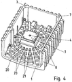
- the housing part is trough-like or hood-shaped and the webs are arranged on the inner bottom of the tub or hood.
- the advantage here is that the side walls can be used to dissipate the heat of the other components.
- the heat of the other components via the at least partially enclosed by the housing part air of the interior region of the electrical device is guided to the side walls of the trough or hood, in particular wherein an air flow is convection driven.
- the advantage here is that over the convection-driven air cooling is achievable, but the heat is much less spread apart than in the spreading of the heat of the power module, ie the heat-generating component.
- the housing part is connected to a further housing part of the electrical appliance, wherein a seal, ie heat barrier, is interposed.
- a seal ie heat barrier
- the housing part centering pins for aligning the housing part relative to the other housing part when placing and connecting.
- the wall thickness of the housing part is made thickened in the region of the webs, in the intermediate region of the webs, the wall thickness is smaller than in the area of the webs.
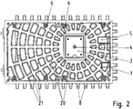
- the housing part 1 is designed as a cover part, which is on a lower part, not shown, in particular motor housing, can be placed.
- the formed on the housing part 1 centering pins 7 are inserted into corresponding centering, in particular conical centering holes, and thus allows a guided and centered connection. Between the cover part and lower part of a seal is providable, so that after connecting the housing part 1 with the lower part of a device is formed in high degree of protection.
- a circuit board equipped with components 2 is arranged and bolted by screws 6 to the cover part 1, wherein the respective screw head of the screws presses the side facing away from the cover part 1 of the circuit board 2 against the cover part 1.
- the cover part 1 has on its outside cooling ribs 8.
- cooling fingers instead of the cooling fins 8 can also be provided.
- the printed circuit board 2 is equipped with electronic components that generate heat.
- a power module which has power semiconductor switches, is connected to conductor tracks of the printed circuit board 2.
- the power module 3 is at a fine machined surface portion of the inside of the lid part 1 is placed.
- the heat generated by the power module 3 can thus be dissipated to the cover part at this contact surface.
- thermal compound is also between the power module 3 and the cover part 1 providable.
- the power module 3 is screwed by means of the screw 4 to the cover part 1. From the screw head of the screw 4, the power module is pressed onto the cover part 1, so that a good thermal contact can be achieved, so a low heat transfer resistance.
- Radial webs 20 extend from this contact surface, wherein the radial webs 20 are directed radially, ie in a straight line, from the center of the surface section.
- the extension direction of the radial webs 20 is therefore straight from the center, wherein the radial webs 20 begin at the edge of the surface portion and extend radially until they hit the side wall of the lid part 1.
- a threaded bore for receiving the screw 4 is arranged, so that the screw axis or Gewindebohrungsstoffachse is aligned parallel to the normal direction of the surface portion just executed.
- the radial webs 20 are regularly spaced from each other in the circumferential direction to the central axis of the threaded bore.
- transverse webs 21 are provided on the inside of the cover part, wherein the transverse webs in the radial direction are regularly spaced from each other.
- the radial webs 20 and the transverse webs 21 are designed as thickenings, ie spatial regions of thickened wall thickness, of the cover part 1 and therefore protrude from the inside of the cover part 1.
- the surface portion is designed substantially rectangular and protrudes in accordance with a flat dome from the inside of the lid part 1 out.
- the webs (20, 21) and the dome acting as the surface section, ie contact surface protrude substantially equidistant from the inside of the cover part 1 or evenly into the interior area covered by the cover part.
- no transverse webs 21 are present and / or the spacing of the radial webs is irregular.
- non-rectilinear webs are used, wherein the webs extend in such a way that the distance increases to the surface portion along the web.
- a cuboid projection 5 is arranged, which protrudes as well as the webs in the covered by the cover part interior area.
- the circuit board 2 has a corresponding recess, so that the cuboid projection 5 protrudes through the recess.
Landscapes
- Physics & Mathematics (AREA)
- Thermal Sciences (AREA)
- Engineering & Computer Science (AREA)
- Microelectronics & Electronic Packaging (AREA)
- Cooling Or The Like Of Electrical Apparatus (AREA)
- Cookers (AREA)
Claims (15)
- Appareil électrique comprenant une partie boîtier (1),
un composant générateur de chaleur étant disposé sur une section de surface du côté intérieur de la partie boîtier (1), en particulier relié à celle-ci de manière thermo-conductrice,
des nervures en saillie étant formées sur le côté intérieur de la partie boîtier (1),
les nervures s'étendant à partir de la section de surface sur le côté intérieur de la partie boîtier (1),
en particulier les nervures pénétrant dans l'espace intérieur de l'appareil électrique qui est recouvert au moins en partie par la partie boîtier (1),
des nervures radiales (20) et des nervures transversales (21) étant présentes en tant que nervures, les nervures radiales (20) étant dirigées en direction radiale à partir d'une droite qui est orientée dans la direction normale à la section de surface en un point de la section de surface,
les nervures radiales (20) et les nervures transversales (21) étant réalisées chaque fois sous la forme d'épaississements, donc de zones spatiales de plus forte épaisseur de paroi de la partie boîtier (1) et faisant saillie du côté intérieur de la partie boîtier (1). - Appareil électrique selon au moins l'une des revendications précédentes,
caractérisé en ce que
la partie boîtier (1) présente des ailettes de refroidissement (8) et/ou des doigts de refroidissement sur son côté extérieur. - Appareil électrique selon au moins l'une des revendications précédentes,
caractérisé en ce que
la section de surface est en saillie sur le côté intérieur de la partie boîtier (1). - Appareil électrique selon au moins l'une des revendications précédentes,
caractérisé en ce que
les nervures transversales (21) s'étendent en direction circonférentielle, donc présentent une distance radiale indépendante de l'angle circonférentiel. - Appareil électrique selon au moins l'une des revendications précédentes,
caractérisé en ce que
un trou fileté est disposé dans la section de surface, dont l'axe médian est orienté parallèlement à une direction normale à la section de surface,
des nervures radiales (20) s'étendant en direction radiale à partir de la section de surface,
en particulier, les nervures transversales (21) s'étendant en direction circonférentielle, donc présentant une distance radiale indépendante de l'angle circonférentiel. - Appareil électrique selon au moins l'une des revendications précédentes,
caractérisé en ce que
les nervures radiales (20) sont espacées les unes des autres régulièrement en direction circonférentielle. - Appareil électrique selon au moins l'une des revendications précédentes,
caractérisé en ce que
les nervures transversales (21) sont espacées les unes des autres régulièrement en direction radiale. - Appareil électrique selon au moins l'une des revendications précédentes,
caractérisé en ce que
le composant générateur de chaleur est relié à la partie boîtier (1) au moyen d'une vis insérée dans le trou fileté, le composant générateur de chaleur étant en particulier pressé contre la section de surface. - Appareil électrique selon au moins l'une des revendications précédentes,
caractérisé en ce que
le composant générateur de chaleur est relié électriquement à des pistes conductrices d'une carte de circuits imprimés (2) qui est vissée à la partie boîtier (1) au moyen de vis. - Appareil électrique selon au moins l'une des revendications précédentes,
caractérisé en ce que
la carte de circuits imprimés (2) est équipée d'autres composants qui produisent de la chaleur, au moins sur le côté de la carte de circuits imprimés (2) opposé au côté intérieur de la partie boîtier (1). - Appareil électrique selon au moins l'une des revendications précédentes,
caractérisé en ce que
la partie boîtier (1) est réalisée en forme de cuvette ou de calotte et les nervures sont disposées sur le fond intérieur de la cuvette ou de la calotte. - Appareil électrique selon au moins l'une des revendications précédentes,
caractérisé en ce que
la chaleur des autres composants est conduite par l'air de l'espace intérieur de l'appareil électrique, enfermé au moins partiellement par la partie boîtier (1), vers les parois latérales de la cuvette ou de la calotte, en particulier une circulation d'air étant entraînée par convection. - Appareil électrique selon au moins l'une des revendications précédentes,
caractérisé en ce que
la partie boîtier (1) est reliée à une autre partie boîtier (1) de l'appareil électrique, un joint, donc une barrière athermique, étant disposé entre les deux. - Appareil électrique selon au moins l'une des revendications précédentes,
caractérisé en ce que
la partie boîtier (1) présente des broches de centrage (7) pour aligner la partie boîtier (1) par rapport à l'autre partie boîtier (1) lors de la pose et de la liaison. - Appareil électrique selon au moins l'une des revendications précédentes,
caractérisé en ce que
l'épaisseur de paroi de la partie boîtier (1) est plus forte dans la zone des nervures,
l'épaisseur de paroi étant plus faible dans la zone intermédiaire des nervures que dans la zone des nervures.
Applications Claiming Priority (2)
| Application Number | Priority Date | Filing Date | Title |
|---|---|---|---|
| DE102012008897 | 2012-05-08 | ||
| PCT/EP2013/001112 WO2013167227A2 (fr) | 2012-05-08 | 2013-04-16 | Appareil électrique comprenant une partie boîtier |
Publications (2)
| Publication Number | Publication Date |
|---|---|
| EP2848103A2 EP2848103A2 (fr) | 2015-03-18 |
| EP2848103B1 true EP2848103B1 (fr) | 2017-02-01 |
Family
ID=48143244
Family Applications (1)
| Application Number | Title | Priority Date | Filing Date |
|---|---|---|---|
| EP13717717.6A Active EP2848103B1 (fr) | 2012-05-08 | 2013-04-16 | Appareil électrique comprenant une partie boîtier |
Country Status (3)
| Country | Link |
|---|---|
| EP (1) | EP2848103B1 (fr) |
| DE (1) | DE102013006539B4 (fr) |
| WO (1) | WO2013167227A2 (fr) |
Cited By (1)
| Publication number | Priority date | Publication date | Assignee | Title |
|---|---|---|---|---|
| EP3954184B1 (fr) * | 2019-04-10 | 2024-06-05 | Sew-Eurodrive GmbH & Co. KG | Dispositif électrique avec une pièce de boîtier |
Families Citing this family (1)
| Publication number | Priority date | Publication date | Assignee | Title |
|---|---|---|---|---|
| WO2021069093A1 (fr) | 2019-10-08 | 2021-04-15 | Sew-Eurodrive Gmbh & Co. Kg | Moteur électrique comprenant une carte de circuits imprimés |
Family Cites Families (5)
| Publication number | Priority date | Publication date | Assignee | Title |
|---|---|---|---|---|
| US6065530A (en) | 1997-05-30 | 2000-05-23 | Alcatel Usa Sourcing, L.P. | Weatherproof design for remote transceiver |
| GB9929800D0 (en) * | 1999-12-17 | 2000-02-09 | Pace Micro Tech Plc | Heat dissipation in electrical apparatus |
| US20070008680A1 (en) | 2005-07-08 | 2007-01-11 | The Agus S | Power converter having housing with improved thermal properties |
| TWI396033B (zh) | 2008-11-07 | 2013-05-11 | Univ Nat Chiao Tung | Multi - frequency electrical signal of the photoelectric device |
| JP2011249520A (ja) | 2010-05-26 | 2011-12-08 | Mitsubishi Electric Corp | 電子制御装置 |
-
2013
- 2013-04-16 DE DE102013006539.9A patent/DE102013006539B4/de active Active
- 2013-04-16 EP EP13717717.6A patent/EP2848103B1/fr active Active
- 2013-04-16 WO PCT/EP2013/001112 patent/WO2013167227A2/fr not_active Ceased
Non-Patent Citations (1)
| Title |
|---|
| None * |
Cited By (1)
| Publication number | Priority date | Publication date | Assignee | Title |
|---|---|---|---|---|
| EP3954184B1 (fr) * | 2019-04-10 | 2024-06-05 | Sew-Eurodrive GmbH & Co. KG | Dispositif électrique avec une pièce de boîtier |
Also Published As
| Publication number | Publication date |
|---|---|
| WO2013167227A2 (fr) | 2013-11-14 |
| WO2013167227A3 (fr) | 2014-04-10 |
| EP2848103A2 (fr) | 2015-03-18 |
| DE102013006539B4 (de) | 2022-11-17 |
| DE102013006539A1 (de) | 2013-11-14 |
Similar Documents
| Publication | Publication Date | Title |
|---|---|---|
| EP3286804B1 (fr) | Élément de connecteur enfichable comportant un moyen de surveillance de temperature | |
| DE112014002124B4 (de) | Elektrischer Kompressor mit integriertem Wechselrichter | |
| EP2671434B1 (fr) | Appareil électrique | |
| DE102015225750B4 (de) | Elektronische vorrichtung und aktuator, der dieselbe verwendet | |
| DE112015005727T5 (de) | Schaltungsanordnung und elektrischer Verteiler | |
| DE112015002430T5 (de) | Schaltungsbaugruppe und elektrischer Verteiler | |
| DE102008033193A1 (de) | Motorsteuerungsvorrichtung eines Fahrzeugs | |
| DE102012001120A1 (de) | Vorrichtung, insbesondere Schaltschrank, mit Gehäuse | |
| DE102014012349A1 (de) | Kühlanordnung | |
| EP3535804B1 (fr) | Platine de liaison d'éléments de batterie | |
| WO2023147816A1 (fr) | Système électrique et unité d'entraînement électrique | |
| EP2848103B1 (fr) | Appareil électrique comprenant une partie boîtier | |
| EP2716145A1 (fr) | Carte de circuits imprimés pour composants électriques et systèmes de cartes de circuits imprimés | |
| EP3295768B1 (fr) | Dispositif de chauffage pour chauffer l'intérieur d'un véhicule automobile | |
| EP0136454A1 (fr) | Dispositif pour la dissipation de chaleur des plaquettes à circuit imprimé | |
| WO2012013254A1 (fr) | Agencement et accumulateur d'énergie comportant un agencement destiné à tempérer, en particulier à refroidir, des composants produisant de la chaleur | |
| DE102009033258B4 (de) | Gehäuse | |
| EP0652694B1 (fr) | Appareil de commande pour automobile | |
| EP2805589B1 (fr) | Appareil electrique | |
| DE102014002522A1 (de) | Batterie mit einer Ableiterkühlung | |
| DE102014203099B4 (de) | Baueinheit mit einem Gehäuse und einem in dem Gehäuse angeordneten Elektronikbauteil | |
| DE102014004798B4 (de) | Elektrisches Gerät | |
| EP3921718B1 (fr) | Système d'ordinateur et corps thermoconducteur | |
| EP1732131A2 (fr) | Assemblage pour dissipation de chaleur d'un groupe de composants electroniques à haute prestation | |
| DE102011010434B4 (de) | Elektrisches Gerät |
Legal Events
| Date | Code | Title | Description |
|---|---|---|---|
| PUAI | Public reference made under article 153(3) epc to a published international application that has entered the european phase |
Free format text: ORIGINAL CODE: 0009012 |
|
| 17P | Request for examination filed |
Effective date: 20141208 |
|
| AK | Designated contracting states |
Kind code of ref document: A2 Designated state(s): AL AT BE BG CH CY CZ DE DK EE ES FI FR GB GR HR HU IE IS IT LI LT LU LV MC MK MT NL NO PL PT RO RS SE SI SK SM TR |
|
| AX | Request for extension of the european patent |
Extension state: BA ME |
|
| DAX | Request for extension of the european patent (deleted) | ||
| GRAP | Despatch of communication of intention to grant a patent |
Free format text: ORIGINAL CODE: EPIDOSNIGR1 |
|
| INTG | Intention to grant announced |
Effective date: 20160916 |
|
| GRAS | Grant fee paid |
Free format text: ORIGINAL CODE: EPIDOSNIGR3 |
|
| GRAA | (expected) grant |
Free format text: ORIGINAL CODE: 0009210 |
|
| AK | Designated contracting states |
Kind code of ref document: B1 Designated state(s): AL AT BE BG CH CY CZ DE DK EE ES FI FR GB GR HR HU IE IS IT LI LT LU LV MC MK MT NL NO PL PT RO RS SE SI SK SM TR |
|
| REG | Reference to a national code |
Ref country code: GB Ref legal event code: FG4D Free format text: NOT ENGLISH |
|
| REG | Reference to a national code |
Ref country code: CH Ref legal event code: EP Ref country code: CH Ref legal event code: NV Representative=s name: HEPP WENGER RYFFEL AG, CH Ref country code: AT Ref legal event code: REF Ref document number: 866457 Country of ref document: AT Kind code of ref document: T Effective date: 20170215 |
|
| REG | Reference to a national code |
Ref country code: FR Ref legal event code: PLFP Year of fee payment: 5 |
|
| REG | Reference to a national code |
Ref country code: IE Ref legal event code: FG4D Free format text: LANGUAGE OF EP DOCUMENT: GERMAN |
|
| REG | Reference to a national code |
Ref country code: DE Ref legal event code: R096 Ref document number: 502013006248 Country of ref document: DE |
|
| REG | Reference to a national code |
Ref country code: SE Ref legal event code: TRGR |
|
| REG | Reference to a national code |
Ref country code: NL Ref legal event code: FP |
|
| REG | Reference to a national code |
Ref country code: LT Ref legal event code: MG4D |
|
| PG25 | Lapsed in a contracting state [announced via postgrant information from national office to epo] |
Ref country code: HR Free format text: LAPSE BECAUSE OF FAILURE TO SUBMIT A TRANSLATION OF THE DESCRIPTION OR TO PAY THE FEE WITHIN THE PRESCRIBED TIME-LIMIT Effective date: 20170201 Ref country code: NO Free format text: LAPSE BECAUSE OF FAILURE TO SUBMIT A TRANSLATION OF THE DESCRIPTION OR TO PAY THE FEE WITHIN THE PRESCRIBED TIME-LIMIT Effective date: 20170501 Ref country code: GR Free format text: LAPSE BECAUSE OF FAILURE TO SUBMIT A TRANSLATION OF THE DESCRIPTION OR TO PAY THE FEE WITHIN THE PRESCRIBED TIME-LIMIT Effective date: 20170502 Ref country code: LT Free format text: LAPSE BECAUSE OF FAILURE TO SUBMIT A TRANSLATION OF THE DESCRIPTION OR TO PAY THE FEE WITHIN THE PRESCRIBED TIME-LIMIT Effective date: 20170201 Ref country code: IS Free format text: LAPSE BECAUSE OF FAILURE TO SUBMIT A TRANSLATION OF THE DESCRIPTION OR TO PAY THE FEE WITHIN THE PRESCRIBED TIME-LIMIT Effective date: 20170601 |
|
| PG25 | Lapsed in a contracting state [announced via postgrant information from national office to epo] |
Ref country code: LV Free format text: LAPSE BECAUSE OF FAILURE TO SUBMIT A TRANSLATION OF THE DESCRIPTION OR TO PAY THE FEE WITHIN THE PRESCRIBED TIME-LIMIT Effective date: 20170201 Ref country code: ES Free format text: LAPSE BECAUSE OF FAILURE TO SUBMIT A TRANSLATION OF THE DESCRIPTION OR TO PAY THE FEE WITHIN THE PRESCRIBED TIME-LIMIT Effective date: 20170201 Ref country code: PT Free format text: LAPSE BECAUSE OF FAILURE TO SUBMIT A TRANSLATION OF THE DESCRIPTION OR TO PAY THE FEE WITHIN THE PRESCRIBED TIME-LIMIT Effective date: 20170601 Ref country code: RS Free format text: LAPSE BECAUSE OF FAILURE TO SUBMIT A TRANSLATION OF THE DESCRIPTION OR TO PAY THE FEE WITHIN THE PRESCRIBED TIME-LIMIT Effective date: 20170201 Ref country code: PL Free format text: LAPSE BECAUSE OF FAILURE TO SUBMIT A TRANSLATION OF THE DESCRIPTION OR TO PAY THE FEE WITHIN THE PRESCRIBED TIME-LIMIT Effective date: 20170201 Ref country code: BG Free format text: LAPSE BECAUSE OF FAILURE TO SUBMIT A TRANSLATION OF THE DESCRIPTION OR TO PAY THE FEE WITHIN THE PRESCRIBED TIME-LIMIT Effective date: 20170501 |
|
| PG25 | Lapsed in a contracting state [announced via postgrant information from national office to epo] |
Ref country code: EE Free format text: LAPSE BECAUSE OF FAILURE TO SUBMIT A TRANSLATION OF THE DESCRIPTION OR TO PAY THE FEE WITHIN THE PRESCRIBED TIME-LIMIT Effective date: 20170201 Ref country code: RO Free format text: LAPSE BECAUSE OF FAILURE TO SUBMIT A TRANSLATION OF THE DESCRIPTION OR TO PAY THE FEE WITHIN THE PRESCRIBED TIME-LIMIT Effective date: 20170201 Ref country code: SK Free format text: LAPSE BECAUSE OF FAILURE TO SUBMIT A TRANSLATION OF THE DESCRIPTION OR TO PAY THE FEE WITHIN THE PRESCRIBED TIME-LIMIT Effective date: 20170201 Ref country code: CZ Free format text: LAPSE BECAUSE OF FAILURE TO SUBMIT A TRANSLATION OF THE DESCRIPTION OR TO PAY THE FEE WITHIN THE PRESCRIBED TIME-LIMIT Effective date: 20170201 |
|
| REG | Reference to a national code |
Ref country code: DE Ref legal event code: R097 Ref document number: 502013006248 Country of ref document: DE |
|
| PG25 | Lapsed in a contracting state [announced via postgrant information from national office to epo] |
Ref country code: SM Free format text: LAPSE BECAUSE OF FAILURE TO SUBMIT A TRANSLATION OF THE DESCRIPTION OR TO PAY THE FEE WITHIN THE PRESCRIBED TIME-LIMIT Effective date: 20170201 Ref country code: DK Free format text: LAPSE BECAUSE OF FAILURE TO SUBMIT A TRANSLATION OF THE DESCRIPTION OR TO PAY THE FEE WITHIN THE PRESCRIBED TIME-LIMIT Effective date: 20170201 |
|
| PLBE | No opposition filed within time limit |
Free format text: ORIGINAL CODE: 0009261 |
|
| STAA | Information on the status of an ep patent application or granted ep patent |
Free format text: STATUS: NO OPPOSITION FILED WITHIN TIME LIMIT |
|
| 26N | No opposition filed |
Effective date: 20171103 |
|
| REG | Reference to a national code |
Ref country code: IE Ref legal event code: MM4A |
|
| PG25 | Lapsed in a contracting state [announced via postgrant information from national office to epo] |
Ref country code: MC Free format text: LAPSE BECAUSE OF FAILURE TO SUBMIT A TRANSLATION OF THE DESCRIPTION OR TO PAY THE FEE WITHIN THE PRESCRIBED TIME-LIMIT Effective date: 20170201 |
|
| PG25 | Lapsed in a contracting state [announced via postgrant information from national office to epo] |
Ref country code: LU Free format text: LAPSE BECAUSE OF NON-PAYMENT OF DUE FEES Effective date: 20170416 Ref country code: SI Free format text: LAPSE BECAUSE OF FAILURE TO SUBMIT A TRANSLATION OF THE DESCRIPTION OR TO PAY THE FEE WITHIN THE PRESCRIBED TIME-LIMIT Effective date: 20170201 |
|
| REG | Reference to a national code |
Ref country code: FR Ref legal event code: PLFP Year of fee payment: 6 |
|
| REG | Reference to a national code |
Ref country code: BE Ref legal event code: MM Effective date: 20170430 |
|
| PG25 | Lapsed in a contracting state [announced via postgrant information from national office to epo] |
Ref country code: IE Free format text: LAPSE BECAUSE OF NON-PAYMENT OF DUE FEES Effective date: 20170416 |
|
| PG25 | Lapsed in a contracting state [announced via postgrant information from national office to epo] |
Ref country code: BE Free format text: LAPSE BECAUSE OF NON-PAYMENT OF DUE FEES Effective date: 20170430 |
|
| PG25 | Lapsed in a contracting state [announced via postgrant information from national office to epo] |
Ref country code: MT Free format text: LAPSE BECAUSE OF FAILURE TO SUBMIT A TRANSLATION OF THE DESCRIPTION OR TO PAY THE FEE WITHIN THE PRESCRIBED TIME-LIMIT Effective date: 20170201 |
|
| PG25 | Lapsed in a contracting state [announced via postgrant information from national office to epo] |
Ref country code: HU Free format text: LAPSE BECAUSE OF FAILURE TO SUBMIT A TRANSLATION OF THE DESCRIPTION OR TO PAY THE FEE WITHIN THE PRESCRIBED TIME-LIMIT; INVALID AB INITIO Effective date: 20130416 |
|
| PG25 | Lapsed in a contracting state [announced via postgrant information from national office to epo] |
Ref country code: CY Free format text: LAPSE BECAUSE OF FAILURE TO SUBMIT A TRANSLATION OF THE DESCRIPTION OR TO PAY THE FEE WITHIN THE PRESCRIBED TIME-LIMIT Effective date: 20170201 |
|
| PG25 | Lapsed in a contracting state [announced via postgrant information from national office to epo] |
Ref country code: MK Free format text: LAPSE BECAUSE OF FAILURE TO SUBMIT A TRANSLATION OF THE DESCRIPTION OR TO PAY THE FEE WITHIN THE PRESCRIBED TIME-LIMIT Effective date: 20170201 |
|
| PG25 | Lapsed in a contracting state [announced via postgrant information from national office to epo] |
Ref country code: TR Free format text: LAPSE BECAUSE OF FAILURE TO SUBMIT A TRANSLATION OF THE DESCRIPTION OR TO PAY THE FEE WITHIN THE PRESCRIBED TIME-LIMIT Effective date: 20170201 |
|
| PG25 | Lapsed in a contracting state [announced via postgrant information from national office to epo] |
Ref country code: AL Free format text: LAPSE BECAUSE OF FAILURE TO SUBMIT A TRANSLATION OF THE DESCRIPTION OR TO PAY THE FEE WITHIN THE PRESCRIBED TIME-LIMIT Effective date: 20170201 |
|
| PGFP | Annual fee paid to national office [announced via postgrant information from national office to epo] |
Ref country code: FI Payment date: 20250421 Year of fee payment: 13 |
|
| PGFP | Annual fee paid to national office [announced via postgrant information from national office to epo] |
Ref country code: DE Payment date: 20250430 Year of fee payment: 13 |
|
| PGFP | Annual fee paid to national office [announced via postgrant information from national office to epo] |
Ref country code: CH Payment date: 20250501 Year of fee payment: 13 |
|
| PGFP | Annual fee paid to national office [announced via postgrant information from national office to epo] |
Ref country code: AT Payment date: 20250409 Year of fee payment: 13 |
|
| PGFP | Annual fee paid to national office [announced via postgrant information from national office to epo] |
Ref country code: SE Payment date: 20260312 Year of fee payment: 14 |
|
| PGFP | Annual fee paid to national office [announced via postgrant information from national office to epo] |
Ref country code: GB Payment date: 20260312 Year of fee payment: 14 |
|
| PGFP | Annual fee paid to national office [announced via postgrant information from national office to epo] |
Ref country code: IT Payment date: 20260320 Year of fee payment: 14 |
|
| PGFP | Annual fee paid to national office [announced via postgrant information from national office to epo] |
Ref country code: NL Payment date: 20260317 Year of fee payment: 14 |
|
| PGFP | Annual fee paid to national office [announced via postgrant information from national office to epo] |
Ref country code: FR Payment date: 20260309 Year of fee payment: 14 |