EP2851183A1 - A method for applying fibre material on a vertical surface - Google Patents
A method for applying fibre material on a vertical surface Download PDFInfo
- Publication number
- EP2851183A1 EP2851183A1 EP20130185157 EP13185157A EP2851183A1 EP 2851183 A1 EP2851183 A1 EP 2851183A1 EP 20130185157 EP20130185157 EP 20130185157 EP 13185157 A EP13185157 A EP 13185157A EP 2851183 A1 EP2851183 A1 EP 2851183A1
- Authority
- EP
- European Patent Office
- Prior art keywords
- fibre material
- applying
- vertical surface
- adhesive
- fibre
- Prior art date
- Legal status (The legal status is an assumption and is not a legal conclusion. Google has not performed a legal analysis and makes no representation as to the accuracy of the status listed.)
- Granted
Links
- 239000000463 material Substances 0.000 title claims abstract description 80
- 239000000835 fiber Substances 0.000 title claims abstract description 77
- 238000000034 method Methods 0.000 title claims abstract description 33
- 239000000853 adhesive Substances 0.000 claims abstract description 22
- 230000001070 adhesive effect Effects 0.000 claims abstract description 22
- 239000011347 resin Substances 0.000 claims abstract description 12
- 229920005989 resin Polymers 0.000 claims abstract description 12
- 238000005507 spraying Methods 0.000 claims abstract description 11
- 239000003365 glass fiber Substances 0.000 claims description 21
- OKTJSMMVPCPJKN-UHFFFAOYSA-N Carbon Chemical compound [C] OKTJSMMVPCPJKN-UHFFFAOYSA-N 0.000 claims description 5
- 229910052799 carbon Inorganic materials 0.000 claims description 5
- 239000002023 wood Substances 0.000 claims description 4
- 239000004744 fabric Substances 0.000 claims description 3
- 229920002994 synthetic fiber Polymers 0.000 claims description 3
- 238000001721 transfer moulding Methods 0.000 claims description 3
- 239000006260 foam Substances 0.000 claims description 2
- 238000010276 construction Methods 0.000 description 24
- 239000010410 layer Substances 0.000 description 11
- 238000007796 conventional method Methods 0.000 description 3
- 238000013461 design Methods 0.000 description 3
- 238000011161 development Methods 0.000 description 3
- 239000000203 mixture Substances 0.000 description 3
- 239000012790 adhesive layer Substances 0.000 description 2
- 238000004519 manufacturing process Methods 0.000 description 2
- 239000007921 spray Substances 0.000 description 2
- 239000010409 thin film Substances 0.000 description 2
- 239000002131 composite material Substances 0.000 description 1
- 239000007788 liquid Substances 0.000 description 1
- 238000012986 modification Methods 0.000 description 1
- 230000004048 modification Effects 0.000 description 1
- 238000003825 pressing Methods 0.000 description 1
- 239000002356 single layer Substances 0.000 description 1
- 239000000126 substance Substances 0.000 description 1
- 230000037303 wrinkles Effects 0.000 description 1
Images

Classifications
-
- B—PERFORMING OPERATIONS; TRANSPORTING
- B29—WORKING OF PLASTICS; WORKING OF SUBSTANCES IN A PLASTIC STATE IN GENERAL
- B29C—SHAPING OR JOINING OF PLASTICS; SHAPING OF MATERIAL IN A PLASTIC STATE, NOT OTHERWISE PROVIDED FOR; AFTER-TREATMENT OF THE SHAPED PRODUCTS, e.g. REPAIRING
- B29C70/00—Shaping composites, i.e. plastics material comprising reinforcements, fillers or preformed parts, e.g. inserts
- B29C70/04—Shaping composites, i.e. plastics material comprising reinforcements, fillers or preformed parts, e.g. inserts comprising reinforcements only, e.g. self-reinforcing plastics
- B29C70/28—Shaping operations therefor
- B29C70/30—Shaping by lay-up, i.e. applying fibres, tape or broadsheet on a mould, former or core; Shaping by spray-up, i.e. spraying of fibres on a mould, former or core
-
- B—PERFORMING OPERATIONS; TRANSPORTING
- B29—WORKING OF PLASTICS; WORKING OF SUBSTANCES IN A PLASTIC STATE IN GENERAL
- B29C—SHAPING OR JOINING OF PLASTICS; SHAPING OF MATERIAL IN A PLASTIC STATE, NOT OTHERWISE PROVIDED FOR; AFTER-TREATMENT OF THE SHAPED PRODUCTS, e.g. REPAIRING
- B29C70/00—Shaping composites, i.e. plastics material comprising reinforcements, fillers or preformed parts, e.g. inserts
- B29C70/04—Shaping composites, i.e. plastics material comprising reinforcements, fillers or preformed parts, e.g. inserts comprising reinforcements only, e.g. self-reinforcing plastics
- B29C70/28—Shaping operations therefor
- B29C70/30—Shaping by lay-up, i.e. applying fibres, tape or broadsheet on a mould, former or core; Shaping by spray-up, i.e. spraying of fibres on a mould, former or core
- B29C70/38—Automated lay-up, e.g. using robots, laying filaments according to predetermined patterns
-
- B—PERFORMING OPERATIONS; TRANSPORTING
- B29—WORKING OF PLASTICS; WORKING OF SUBSTANCES IN A PLASTIC STATE IN GENERAL
- B29C—SHAPING OR JOINING OF PLASTICS; SHAPING OF MATERIAL IN A PLASTIC STATE, NOT OTHERWISE PROVIDED FOR; AFTER-TREATMENT OF THE SHAPED PRODUCTS, e.g. REPAIRING
- B29C70/00—Shaping composites, i.e. plastics material comprising reinforcements, fillers or preformed parts, e.g. inserts
- B29C70/04—Shaping composites, i.e. plastics material comprising reinforcements, fillers or preformed parts, e.g. inserts comprising reinforcements only, e.g. self-reinforcing plastics
- B29C70/28—Shaping operations therefor
- B29C70/40—Shaping or impregnating by compression not applied
- B29C70/42—Shaping or impregnating by compression not applied for producing articles of definite length, i.e. discrete articles
- B29C70/44—Shaping or impregnating by compression not applied for producing articles of definite length, i.e. discrete articles using isostatic pressure, e.g. pressure difference-moulding, vacuum bag-moulding, autoclave-moulding or expanding rubber-moulding
- B29C70/443—Shaping or impregnating by compression not applied for producing articles of definite length, i.e. discrete articles using isostatic pressure, e.g. pressure difference-moulding, vacuum bag-moulding, autoclave-moulding or expanding rubber-moulding and impregnating by vacuum or injection
-
- B—PERFORMING OPERATIONS; TRANSPORTING
- B29—WORKING OF PLASTICS; WORKING OF SUBSTANCES IN A PLASTIC STATE IN GENERAL
- B29C—SHAPING OR JOINING OF PLASTICS; SHAPING OF MATERIAL IN A PLASTIC STATE, NOT OTHERWISE PROVIDED FOR; AFTER-TREATMENT OF THE SHAPED PRODUCTS, e.g. REPAIRING
- B29C70/00—Shaping composites, i.e. plastics material comprising reinforcements, fillers or preformed parts, e.g. inserts
- B29C70/04—Shaping composites, i.e. plastics material comprising reinforcements, fillers or preformed parts, e.g. inserts comprising reinforcements only, e.g. self-reinforcing plastics
- B29C70/28—Shaping operations therefor
- B29C70/54—Component parts, details or accessories; Auxiliary operations, e.g. feeding or storage of prepregs or SMC after impregnation or during ageing
- B29C70/541—Positioning reinforcements in a mould, e.g. using clamping means for the reinforcement
-
- B—PERFORMING OPERATIONS; TRANSPORTING
- B29—WORKING OF PLASTICS; WORKING OF SUBSTANCES IN A PLASTIC STATE IN GENERAL
- B29K—INDEXING SCHEME ASSOCIATED WITH SUBCLASSES B29B, B29C OR B29D, RELATING TO MOULDING MATERIALS OR TO MATERIALS FOR MOULDS, REINFORCEMENTS, FILLERS OR PREFORMED PARTS, e.g. INSERTS
- B29K2105/00—Condition, form or state of moulded material or of the material to be shaped
- B29K2105/0058—Liquid or visquous
-
- B—PERFORMING OPERATIONS; TRANSPORTING
- B29—WORKING OF PLASTICS; WORKING OF SUBSTANCES IN A PLASTIC STATE IN GENERAL
- B29K—INDEXING SCHEME ASSOCIATED WITH SUBCLASSES B29B, B29C OR B29D, RELATING TO MOULDING MATERIALS OR TO MATERIALS FOR MOULDS, REINFORCEMENTS, FILLERS OR PREFORMED PARTS, e.g. INSERTS
- B29K2105/00—Condition, form or state of moulded material or of the material to be shaped
- B29K2105/06—Condition, form or state of moulded material or of the material to be shaped containing reinforcements, fillers or inserts
- B29K2105/08—Condition, form or state of moulded material or of the material to be shaped containing reinforcements, fillers or inserts of continuous length, e.g. cords, rovings, mats, fabrics, strands or yarns
- B29K2105/0809—Fabrics
-
- B—PERFORMING OPERATIONS; TRANSPORTING
- B29—WORKING OF PLASTICS; WORKING OF SUBSTANCES IN A PLASTIC STATE IN GENERAL
- B29L—INDEXING SCHEME ASSOCIATED WITH SUBCLASS B29C, RELATING TO PARTICULAR ARTICLES
- B29L2031/00—Other particular articles
- B29L2031/08—Blades for rotors, stators, fans, turbines or the like, e.g. screw propellers
- B29L2031/082—Blades, e.g. for helicopters
- B29L2031/085—Wind turbine blades
-
- Y—GENERAL TAGGING OF NEW TECHNOLOGICAL DEVELOPMENTS; GENERAL TAGGING OF CROSS-SECTIONAL TECHNOLOGIES SPANNING OVER SEVERAL SECTIONS OF THE IPC; TECHNICAL SUBJECTS COVERED BY FORMER USPC CROSS-REFERENCE ART COLLECTIONS [XRACs] AND DIGESTS
- Y02—TECHNOLOGIES OR APPLICATIONS FOR MITIGATION OR ADAPTATION AGAINST CLIMATE CHANGE
- Y02P—CLIMATE CHANGE MITIGATION TECHNOLOGIES IN THE PRODUCTION OR PROCESSING OF GOODS
- Y02P70/00—Climate change mitigation technologies in the production process for final industrial or consumer products
- Y02P70/50—Manufacturing or production processes characterised by the final manufactured product
-
- Y—GENERAL TAGGING OF NEW TECHNOLOGICAL DEVELOPMENTS; GENERAL TAGGING OF CROSS-SECTIONAL TECHNOLOGIES SPANNING OVER SEVERAL SECTIONS OF THE IPC; TECHNICAL SUBJECTS COVERED BY FORMER USPC CROSS-REFERENCE ART COLLECTIONS [XRACs] AND DIGESTS
- Y10—TECHNICAL SUBJECTS COVERED BY FORMER USPC
- Y10T—TECHNICAL SUBJECTS COVERED BY FORMER US CLASSIFICATION
- Y10T156/00—Adhesive bonding and miscellaneous chemical manufacture
- Y10T156/10—Methods of surface bonding and/or assembly therefor
Definitions
- the present invention relates to a method for applying fibre material on a vertical surface.
- Rotor blades for wind turbines are made by laying a fibre material on a mould surface resembling a negative image of the fibre reinforced structure to be produced and in which a resin is infused and cured after the fibre material is laid on the mould surface.
- the form of such a blade is that is has a suction side and a pressure side with a shape determined by aerodynamical requirements. In a typical blade construction both sides are held in relation to each other by a beam, a spar or a web. Normally the web is casted or produced as a separate piece and afterwards being established together with other laid parts such as by using adhesives.
- the web can be an integral part of a moulded structure and casted together with e.g. one or both of the sides of the blade. Basically the web is a structure which extends substantially perpendicular to the sides of the blades, therefore it is a challenge to build these parts together in a mould.
- Fig. 1 shows a blade mould 1 in which a glass fibre material 2 is laid out as a first side.
- Fig. 2 shows a vertical web construction 3 on which glass fibre material 4 is applied at a position remote from the blade mould 1. After building the vertical web construction 3 with said glass fibre material 4 the web construction 3 is lifted and positioned on the glass fibre material 2 in the blade mould 1 as is shown in fig. 3.
- Fig. 4 is a perspective view of the vertical web construction 3 of fig. 2 whereby the vertical web construction 3 is made from wood and a plurality of glass fibre mats 5 is applied and laid on the vertical surface.
- this object is achieved in the above defined method by the following steps: spraying an adhesive on the vertical surface, applying the fibre material on the sprayed surface, spraying additional adhesive on the fibre material for another layer of fibre material, applying another layer of fibre material on the sprayed fibre material, and injecting the layers of fibre material with a resin.
- the invention is based on the idea that a fibre material can be applied on a vertical surface, whereby less production facility space is required by adhering said fibre material to the surface during layout.
- a beam or web can be produced directly in the mould during layout. It is advantageous that the web can be constructed while being positioned in a blade mould. Hereby it is not necessary to lift the web construction from a remote position into the mould. Accordingly this is both time and cost effective.
- Another advantage of the invention is that it enables the layout of a fibre material on substantially vertical and highly angled surfaces.
- the fibre material is unrolled from a reel. Accordingly the fibre material is unrolled from said reel and directly attached to the vertical surface and held in place by the adhesive.
- a glass fibre material and/or a carbon fibre material and/or a synthetic fibre material is preferred as fibre material.
- the actual layout depends on the design of a wind turbine blade. Normally it consists of several fibre material layers which are applied in different directions, namely with different fibre angles. It is possible that one wind turbine blade consists e.g. of a mixture of glass fibre material and carbon fibre material and/or at least one synthetic fibre material.
- a fibre material in the form of a mat or a fabric is used.
- the use of a mat or a fabric enables to cover the surface of a vertical web construction very quickly. Subsequently an adhesive is applied on the fibre material, so that another layer of fibre material can be laid up.
- a vertical surface which is made of wood or foam.
- An adhesive is sprayed on said vertical surface, subsequently the fibre material is applied on the sprayed surface.
- said fibre material is applied on both sides of the vertical surface. Accordingly a symmetric laminate or an unsymmetric laminate can be produced, as is required by design constraints.
- the resin can be injected in a vacuum assisted resin transfer molding (VARTM) process.
- VARTM vacuum assisted resin transfer molding
- the vertical web construction and/or the mould surface which are covered with a dry fibre material is covered by a thin film, subsequently air is sucked out between the thin film and the mould surface and the vertical web construction, respectively, and a liquid resin is injected in order to embed the fibre material into resin.
- the inventive method can be performed very economically in that the step of spraying an adhesive and/or the step of applying a fibre material is performed by an automatic actuator or a robot, in particular an industrial robot. Accordingly the layup of fibre material can be performed automatically under the control of a controller.
- said actuator or said robot comprises a means for exerting pressure to applied fibre material.
- the fibre material which is unrolled from a reel is pressed to the vertical web construction, the fibre material is held in place after being positioned, so that no wrinkles can occur. Unrolling said fibre material from a reel is simply effected by moving said reel, when the positioned fibre material is pressed onto the vertical web construction and its adhesive by said pressure means.
- the method for applying fibre material is explained with regard to fig. 5 to fig. 12 .
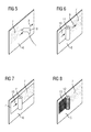
- Fig. 5 shows a vertical surface, namely a vertical web construction 6 made from wood on which it is desired to build up a fibre structure which in turn is to be moulded to a composite fibre component.
- the fibre material is glass fibre.
- other embodiments are possible, where carbon fibre or a mixture of glass fibre and carbon fibre is used.
- a thin layer of an adhesive 7 is sprayed on the vertical web construction 6 by a spray gun 8 which is moved along the surface of the vertical web construction 6 as is indicated by arrows 9.
- Spraying the adhesive can be done manually or automatically, e.g. by a robot.
- the vertical web construction is positioned above a mould for a wind turbine blade, accordingly the vertical web construction 6 is directly established at a position where it is needed for building up a fibre structure.
- a glass fibre mat 10 is established on the sprayed area as is schematically illustrated in fig. 6 .
- the glass fibre mat 10 is rolled off from a reel 11 and directly attached to the sticky vertical surface of the web construction 6 and held in place.
- each glass fibre mat 10 which is attached to the vertical web construction 6, is covered with a thin layer of adhesive 7.
- Each single layer of glass fibre can be attached in a different, specific angle, as is determined during design of a wind turbine blade.
- An additional adhesive layer 7 is to be sprayed on for every new layer of fibre material which is to be attached for holding this layer.
- a fibre material particular a glass fibre material in the form of mats is used which are established on the thin adhesive layer one by one. Attaching the single mats can be done manually or automatically by a robot.
- a thin layer of adhesive 7 is applied on a vertical web construction 6 by a spray gun 8.
- a glass fibre mat 10 is provided on a reel 11 from which it is unrolled onto the sticky surface of the vertical web construction 6.
- a pressure means 14 is used for pressing the unrolled glass fibre mat 10 onto the vertical surface.
- the pressure means 14 is only shown schematically. It comprises a plate 15 which is spring-loaded so that said pressure means 14 can follow the contour of the vertical surface even if the surface is curved.
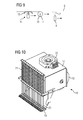
- Fig. 10 is a perspective view of a pressure means 16
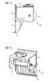
- fig. 11 is a side view of the pressure means 16
- fig. 12 is another perspective view of the pressure means 16.
- Pressure means 16 is explained with regard to fig. 10 , 11 and 12 . It comprises a housing 17 accommodating a reel 18, on which a fibre material, in particular a glass fibre mat is wound.
- the pressure means 16 comprises a number of separate plates 19, which are arranged in a row. Each plate 19 is connected to a rod 20 which is loaded by a spring 21. In fig. 11 one can see that when a fibre mat or a roving is unreeled from a reel 18 it is pressed onto a surface by said plate 19. As the plate 19 is spring-loaded it can even follow a curved surface.
- the pressure means 16 can be used for fibre mats as well as for rovings which are wound in parallel on a reel.
- a connector 22 for an industrial robot is provided so that the pressure means 16 can be moved along a vertical web construction or along a mould by an industrial robot.
Landscapes
- Engineering & Computer Science (AREA)
- Chemical & Material Sciences (AREA)
- Composite Materials (AREA)
- Mechanical Engineering (AREA)
- Robotics (AREA)
- Moulding By Coating Moulds (AREA)
- Laminated Bodies (AREA)
Abstract
- spraying an adhesive (7) on the vertical surface;
- applying the fibre material on the sprayed surface;
- spraying additional adhesive (7) on the fibre material for another layer of fibre material;
- applying another layer of fibre material on the sprayed fibre material; and
- injecting the layers of fibre material with a resin.
Description
- The present invention relates to a method for applying fibre material on a vertical surface.
- Rotor blades for wind turbines are made by laying a fibre material on a mould surface resembling a negative image of the fibre reinforced structure to be produced and in which a resin is infused and cured after the fibre material is laid on the mould surface. The form of such a blade is that is has a suction side and a pressure side with a shape determined by aerodynamical requirements. In a typical blade construction both sides are held in relation to each other by a beam, a spar or a web. Normally the web is casted or produced as a separate piece and afterwards being established together with other laid parts such as by using adhesives. As an alternative it is known that the web can be an integral part of a moulded structure and casted together with e.g. one or both of the sides of the blade. Basically the web is a structure which extends substantially perpendicular to the sides of the blades, therefore it is a challenge to build these parts together in a mould.
- It is a known method to layout and build the web on a location remote to the blade moulds and subsequently lift and place the web in position in the mould so as to form the structure for being casted. This conventional method is shown in
fig. 1 to 3 . -
Fig. 1 shows a blade mould 1 in which aglass fibre material 2 is laid out as a first side.Fig. 2 shows avertical web construction 3 on whichglass fibre material 4 is applied at a position remote from the blade mould 1. After building thevertical web construction 3 with saidglass fibre material 4 theweb construction 3 is lifted and positioned on theglass fibre material 2 in the blade mould 1 as is shown infig. 3. Fig. 4 is a perspective view of thevertical web construction 3 offig. 2 whereby thevertical web construction 3 is made from wood and a plurality ofglass fibre mats 5 is applied and laid on the vertical surface. - However, this conventional method is time consuming and requires much production facility space, as space is required for both the blade moulds and for the construction of the web.
- It is therefore an object of the present invention to provide an easier method for applying a fibre material on a vertical surface.
- According to the present invention this object is achieved in the above defined method by the following steps: spraying an adhesive on the vertical surface, applying the fibre material on the sprayed surface, spraying additional adhesive on the fibre material for another layer of fibre material, applying another layer of fibre material on the sprayed fibre material, and injecting the layers of fibre material with a resin.
- The invention is based on the idea that a fibre material can be applied on a vertical surface, whereby less production facility space is required by adhering said fibre material to the surface during layout. According to the invention a beam or web can be produced directly in the mould during layout. It is advantageous that the web can be constructed while being positioned in a blade mould. Hereby it is not necessary to lift the web construction from a remote position into the mould. Accordingly this is both time and cost effective.
- Another advantage of the invention is that it enables the layout of a fibre material on substantially vertical and highly angled surfaces.
- According to a further development of the invention the fibre material is unrolled from a reel. Accordingly the fibre material is unrolled from said reel and directly attached to the vertical surface and held in place by the adhesive.
- In the inventive method a glass fibre material and/or a carbon fibre material and/or a synthetic fibre material is preferred as fibre material. The actual layout depends on the design of a wind turbine blade. Normally it consists of several fibre material layers which are applied in different directions, namely with different fibre angles. It is possible that one wind turbine blade consists e.g. of a mixture of glass fibre material and carbon fibre material and/or at least one synthetic fibre material.
- It is particularly preferred that a fibre material in the form of a mat or a fabric is used. The use of a mat or a fabric enables to cover the surface of a vertical web construction very quickly. Subsequently an adhesive is applied on the fibre material, so that another layer of fibre material can be laid up.
- According to a further development of the invention a vertical surface is used which is made of wood or foam. An adhesive is sprayed on said vertical surface, subsequently the fibre material is applied on the sprayed surface.
- In the inventive method it is preferred that said fibre material is applied on both sides of the vertical surface. Accordingly a symmetric laminate or an unsymmetric laminate can be produced, as is required by design constraints.
- According to the inventive method the resin can be injected in a vacuum assisted resin transfer molding (VARTM) process. According to this method the vertical web construction and/or the mould surface which are covered with a dry fibre material is covered by a thin film, subsequently air is sucked out between the thin film and the mould surface and the vertical web construction, respectively, and a liquid resin is injected in order to embed the fibre material into resin.
- The inventive method can be performed very economically in that the step of spraying an adhesive and/or the step of applying a fibre material is performed by an automatic actuator or a robot, in particular an industrial robot. Accordingly the layup of fibre material can be performed automatically under the control of a controller.
- According to a further development of the inventive method said actuator or said robot comprises a means for exerting pressure to applied fibre material. As the fibre material which is unrolled from a reel is pressed to the vertical web construction, the fibre material is held in place after being positioned, so that no wrinkles can occur. Unrolling said fibre material from a reel is simply effected by moving said reel, when the positioned fibre material is pressed onto the vertical web construction and its adhesive by said pressure means.
- The invention and its underlying principle will be better understood when consideration is given to the following detailed description of preferred embodiments.
- In the accompanying drawings:
- fig. 1 - 4
- show a conventional method for applying fibre material;
- fig. 5
- shows the step of spraying an adhesive of the inventive method;
- fig. 6
- shows the step of applying the fibre material of the inventive method;
- fig. 7
- shows the step of applying multiple layers of fibre material of the inventive method;
- fig. 8
- shows the step of applying fibre material in form of rovings of the inventive method;
- fig. 9
- shows how fibre material is pressed onto the adhesive by a pressure means; and
- fig. 10 - 12
- show various views of a pressure means.
- The method for applying fibre material is explained with regard to
fig. 5 to fig. 12 . -
Fig. 5 shows a vertical surface, namely avertical web construction 6 made from wood on which it is desired to build up a fibre structure which in turn is to be moulded to a composite fibre component. In this embodiment the fibre material is glass fibre. However, other embodiments are possible, where carbon fibre or a mixture of glass fibre and carbon fibre is used. - In a first step of the method for applying fibre material a thin layer of an
adhesive 7 is sprayed on thevertical web construction 6 by aspray gun 8 which is moved along the surface of thevertical web construction 6 as is indicated byarrows 9. Spraying the adhesive can be done manually or automatically, e.g. by a robot. - It is preferred that the vertical web construction is positioned above a mould for a wind turbine blade, accordingly the
vertical web construction 6 is directly established at a position where it is needed for building up a fibre structure. - After spraying the adhesive on the
vertical web construction 6, whereby the adhesive is not yet cured, aglass fibre mat 10 is established on the sprayed area as is schematically illustrated infig. 6 . Theglass fibre mat 10 is rolled off from areel 11 and directly attached to the sticky vertical surface of theweb construction 6 and held in place. - In
fig. 7 it is shown that multiple layers ofglass fibre mats 10 can be laid out on top of each other, whereby eachglass fibre mat 10, which is attached to thevertical web construction 6, is covered with a thin layer ofadhesive 7. Each single layer of glass fibre can be attached in a different, specific angle, as is determined during design of a wind turbine blade. An additionaladhesive layer 7 is to be sprayed on for every new layer of fibre material which is to be attached for holding this layer. - It is possible to use an adhesive for fixing the layers of glass fibre which is of a chemical composition which is desolved by resin injected in a vacuum assisted resin transfer molding (VARTM) process.
- According to a modification of the method a fibre material particular a glass fibre material in the form of mats is used which are established on the thin adhesive layer one by one. Attaching the single mats can be done manually or automatically by a robot.
-
Fig. 8 shows another embodiment of the method, whereby a glass fibre material in form of rovings is used. These rovings are provided on areel 12 on which rovings 13 have been wound up. -
Fig. 9 shows another embodiment of the method for applying fibre material on a vertical surface, whereby a fibre material is pressed on the vertical surface by a pressure means. - Firstly a thin layer of
adhesive 7 is applied on avertical web construction 6 by aspray gun 8. Aglass fibre mat 10 is provided on areel 11 from which it is unrolled onto the sticky surface of thevertical web construction 6. A pressure means 14 is used for pressing the unrolledglass fibre mat 10 onto the vertical surface. Infig. 9 the pressure means 14 is only shown schematically. It comprises aplate 15 which is spring-loaded so that said pressure means 14 can follow the contour of the vertical surface even if the surface is curved. -
Fig. 10 is a perspective view of a pressure means 16,fig. 11 is a side view of the pressure means 16 andfig. 12 is another perspective view of the pressure means 16. - Pressure means 16 is explained with regard to
fig. 10 ,11 and 12 . It comprises ahousing 17 accommodating areel 18, on which a fibre material, in particular a glass fibre mat is wound. - The pressure means 16 comprises a number of
separate plates 19, which are arranged in a row. Eachplate 19 is connected to arod 20 which is loaded by aspring 21. Infig. 11 one can see that when a fibre mat or a roving is unreeled from areel 18 it is pressed onto a surface by saidplate 19. As theplate 19 is spring-loaded it can even follow a curved surface. The pressure means 16 can be used for fibre mats as well as for rovings which are wound in parallel on a reel. - On one side of the pressure means 16 a
connector 22 for an industrial robot is provided so that the pressure means 16 can be moved along a vertical web construction or along a mould by an industrial robot. - Although the present invention has been described in detail with reference to the preferred embodiment, the present invention is not limited by the disclosed examples from which the skilled person is able to derive other variations without departing from the scope of the invention.
Claims (9)
- A method for applying fibre material on a vertical surface, comprising the following steps:- spraying an adhesive (7) on the vertical surface;- applying the fibre material on the sprayed surface;- spraying additional adhesive (7) on the fibre material for another layer of fibre material;- applying another layer of fibre material on the sprayed fibre material; and- injecting the layers of fibre material with a resin.
- A method according to claim 1, characterised in that the fibre material is unrolled from a reel (11, 12, 18).
- A method according to claim 1 or 2, characterised in that a glass fibre material and/or a carbon fibre material and or a synthetic fibre material is used as fibre material.
- A method according to any of the preceding claims, characterised in that a fibre material in the form of a mat or a fabric is used.
- A method according to any of the preceding claims, characterised in that a vertical surface is used which is made of wood or foam.
- A method according to any of the preceding claims, characterised in that fibre material is applied on both sides of the vertical surface.
- A method according to any of the preceding claims, characterised in that the resin is injected in a vacuum assisted resin transfer molding (VARTM) process.
- A method according to any of the preceding claims, characterised in that the step of spraying an adhesive (7) and/or the step of applying a fibre material is performed by an automatic actuator or an industrial robot.
- A method according to claim 8, characterised in that an actuator or a robot is used comprising a means for exerting pressure to an applied fibre material.
Priority Applications (6)
| Application Number | Priority Date | Filing Date | Title |
|---|---|---|---|
| EP13185157.8A EP2851183B1 (en) | 2013-09-19 | 2013-09-19 | A method for applying fibre material on a vertical surface |
| DK13185157.8T DK2851183T3 (en) | 2013-09-19 | 2013-09-19 | Method of applying fibrous material to a vertical surface |
| US14/485,885 US10479030B2 (en) | 2013-09-19 | 2014-09-15 | Method for applying fibre material on a vertical surface of a web of a wind turbine blade |
| CA 2863787 CA2863787A1 (en) | 2013-09-19 | 2014-09-17 | A method for applying fibre material on a vertical surface |
| BR102014023036A BR102014023036A2 (en) | 2013-09-19 | 2014-09-17 | method for applying fiber material to vertical surface |
| CN201410548462.7A CN104441688B (en) | 2013-09-19 | 2014-09-19 | Method for being applied to fibrous material in vertical surface |
Applications Claiming Priority (1)
| Application Number | Priority Date | Filing Date | Title |
|---|---|---|---|
| EP13185157.8A EP2851183B1 (en) | 2013-09-19 | 2013-09-19 | A method for applying fibre material on a vertical surface |
Publications (2)
| Publication Number | Publication Date |
|---|---|
| EP2851183A1 true EP2851183A1 (en) | 2015-03-25 |
| EP2851183B1 EP2851183B1 (en) | 2018-01-17 |
Family
ID=49253099
Family Applications (1)
| Application Number | Title | Priority Date | Filing Date |
|---|---|---|---|
| EP13185157.8A Not-in-force EP2851183B1 (en) | 2013-09-19 | 2013-09-19 | A method for applying fibre material on a vertical surface |
Country Status (6)
| Country | Link |
|---|---|
| US (1) | US10479030B2 (en) |
| EP (1) | EP2851183B1 (en) |
| CN (1) | CN104441688B (en) |
| BR (1) | BR102014023036A2 (en) |
| CA (1) | CA2863787A1 (en) |
| DK (1) | DK2851183T3 (en) |
Cited By (2)
| Publication number | Priority date | Publication date | Assignee | Title |
|---|---|---|---|---|
| WO2018104467A1 (en) | 2016-12-09 | 2018-06-14 | Institut De Recherche Technologique Jules Verne | Cassette, laying head comprising such a cassette, lay-up installation and method, refill method and preparation method |
| US10040255B2 (en) | 2013-05-31 | 2018-08-07 | Siemens Aktiengesellschaft | Rotor blade manufacturing arrangement |
Citations (3)
| Publication number | Priority date | Publication date | Assignee | Title |
|---|---|---|---|---|
| WO1994026505A1 (en) * | 1993-05-14 | 1994-11-24 | Imperial Chemical Industries Plc | Reinforced moulded articles and method of producing same |
| GB2410458A (en) * | 2004-01-27 | 2005-08-03 | David Irving | A moulded fibre reinforced composite product with a core |
| DE102010015199A1 (en) * | 2010-04-16 | 2011-10-20 | Ingo Karb | Apparatus and method for making fibrous webs and component preforms from fibers |
Family Cites Families (8)
| Publication number | Priority date | Publication date | Assignee | Title |
|---|---|---|---|---|
| US3115271A (en) * | 1958-08-15 | 1963-12-24 | Minnesota Mining & Mfg | Method of constructing a reinforced resin, cone-shaped structure and product |
| US3616070A (en) * | 1968-06-25 | 1971-10-26 | Jerome H Lemelson | Layup apparatus |
| FR2128677B1 (en) * | 1971-03-10 | 1975-03-07 | It | |
| US5043033A (en) * | 1991-01-28 | 1991-08-27 | Fyfe Edward R | Process of improving the strength of existing concrete support columns |
| US6146576A (en) * | 1994-08-08 | 2000-11-14 | Intralaminar Heat Cure, Inc. | Method of forming advanced cured resin composite parts |
| JPH09300476A (en) * | 1996-05-08 | 1997-11-25 | Azuma Giken:Kk | Production of spray molded article of fiber reinforced resin |
| US6740185B2 (en) * | 2001-02-06 | 2004-05-25 | General Electric Company | Method of preparing preforms for RTM molding processes |
| DK176335B1 (en) * | 2001-11-13 | 2007-08-20 | Siemens Wind Power As | Process for manufacturing wind turbine blades |
-
2013
- 2013-09-19 EP EP13185157.8A patent/EP2851183B1/en not_active Not-in-force
- 2013-09-19 DK DK13185157.8T patent/DK2851183T3/en active
-
2014
- 2014-09-15 US US14/485,885 patent/US10479030B2/en not_active Expired - Fee Related
- 2014-09-17 CA CA 2863787 patent/CA2863787A1/en not_active Abandoned
- 2014-09-17 BR BR102014023036A patent/BR102014023036A2/en not_active IP Right Cessation
- 2014-09-19 CN CN201410548462.7A patent/CN104441688B/en not_active Expired - Fee Related
Patent Citations (3)
| Publication number | Priority date | Publication date | Assignee | Title |
|---|---|---|---|---|
| WO1994026505A1 (en) * | 1993-05-14 | 1994-11-24 | Imperial Chemical Industries Plc | Reinforced moulded articles and method of producing same |
| GB2410458A (en) * | 2004-01-27 | 2005-08-03 | David Irving | A moulded fibre reinforced composite product with a core |
| DE102010015199A1 (en) * | 2010-04-16 | 2011-10-20 | Ingo Karb | Apparatus and method for making fibrous webs and component preforms from fibers |
Cited By (7)
| Publication number | Priority date | Publication date | Assignee | Title |
|---|---|---|---|---|
| US10040255B2 (en) | 2013-05-31 | 2018-08-07 | Siemens Aktiengesellschaft | Rotor blade manufacturing arrangement |
| US10399287B2 (en) | 2013-05-31 | 2019-09-03 | Siemens Gamesa Renewable Energy A/S | Manufacturing arrangement for the manufacture of a rotor blade |
| US10618228B2 (en) | 2013-05-31 | 2020-04-14 | Siemens Gamesa Renewable Energy A/S | Rotor blade manufacturing arrangement |
| US11034101B2 (en) | 2013-05-31 | 2021-06-15 | Siemens Gamesa Renew Energy A/S | Rotor blade manufacturing arrangement |
| WO2018104467A1 (en) | 2016-12-09 | 2018-06-14 | Institut De Recherche Technologique Jules Verne | Cassette, laying head comprising such a cassette, lay-up installation and method, refill method and preparation method |
| FR3059932A1 (en) * | 2016-12-09 | 2018-06-15 | Institut De Recherche Technologique Jules Verne | CASSETTE, REMOVAL HEAD COMPRISING SUCH A CASSETTE, INSTALLATION, DRAPING METHOD, RECHARGING METHOD AND PREPARATION METHOD |
| US12172391B2 (en) | 2016-12-09 | 2024-12-24 | Institut De Recherche Technologique Jules Verne | Cassette, laying head comprising such a cassette, lay-up installation and method, refill method and preparation method |
Also Published As
| Publication number | Publication date |
|---|---|
| CN104441688B (en) | 2019-01-08 |
| US10479030B2 (en) | 2019-11-19 |
| EP2851183B1 (en) | 2018-01-17 |
| CN104441688A (en) | 2015-03-25 |
| CA2863787A1 (en) | 2015-03-19 |
| DK2851183T3 (en) | 2018-03-05 |
| BR102014023036A2 (en) | 2015-09-08 |
| US20150075713A1 (en) | 2015-03-19 |
Similar Documents
| Publication | Publication Date | Title |
|---|---|---|
| US20120061007A1 (en) | Method of strengthening a wind turbine blade and the strengthened blade | |
| US10688738B2 (en) | Wind turbine blades | |
| WO2011113812A1 (en) | Improved wind turbine blade spar | |
| JP5860277B2 (en) | Airfoil manufacturing system | |
| CA2852544A1 (en) | A method for laying a fibre material on a mould surface | |
| WO2011107166A1 (en) | Method and mould for moulding a wind turbine blade | |
| EP3083459B1 (en) | Fabric positioning apparatus | |
| GB2530072A (en) | Improvements relating to the manufacture of wind turbine blades | |
| US10479030B2 (en) | Method for applying fibre material on a vertical surface of a web of a wind turbine blade | |
| WO2010055061A1 (en) | Method of applying gelcoat and an arrangement performing said method | |
| EP2362824A1 (en) | A method of manufacturing a laminated part from fibre material | |
| US9957949B2 (en) | Perforated vacuum membrane for fibre reinforced laminates | |
| EP2716904A1 (en) | Composite spar cap for a rotor blade of a wind turbine and method of manufacturing the composite spar cap | |
| CN102216059A (en) | Method and system for monitoring and controlling the manufacturing of parts for a wind power plant | |
| EP2915656B1 (en) | A method for manufacturing a component for a wind turbine | |
| RU2637323C2 (en) | Method and device for applying and fixing film on surface of working body or constructive element | |
| CN106042415B (en) | Fixation of fibre fabric layers in modules of wind turbine blades | |
| DK200400032U3 (en) | Robot for manufacturing wind turbine blades | |
| CN104908343A (en) | A method for manufacturing a component for a wind turbine | |
| EP2918401B1 (en) | A non-stitched fiber material, a method and an apparatus | |
| CZ26588U1 (en) | Large-area ribbed composite panel and/or profile plate |
Legal Events
| Date | Code | Title | Description |
|---|---|---|---|
| PUAI | Public reference made under article 153(3) epc to a published international application that has entered the european phase |
Free format text: ORIGINAL CODE: 0009012 |
|
| 17P | Request for examination filed |
Effective date: 20130919 |
|
| AK | Designated contracting states |
Kind code of ref document: A1 Designated state(s): AL AT BE BG CH CY CZ DE DK EE ES FI FR GB GR HR HU IE IS IT LI LT LU LV MC MK MT NL NO PL PT RO RS SE SI SK SM TR |
|
| AX | Request for extension of the european patent |
Extension state: BA ME |
|
| R17P | Request for examination filed (corrected) |
Effective date: 20150918 |
|
| RBV | Designated contracting states (corrected) |
Designated state(s): AL AT BE BG CH CY CZ DE DK EE ES FI FR GB GR HR HU IE IS IT LI LT LU LV MC MK MT NL NO PL PT RO RS SE SI SK SM TR |
|
| 17Q | First examination report despatched |
Effective date: 20161213 |
|
| RAP1 | Party data changed (applicant data changed or rights of an application transferred) |
Owner name: SIEMENS AKTIENGESELLSCHAFT |
|
| GRAP | Despatch of communication of intention to grant a patent |
Free format text: ORIGINAL CODE: EPIDOSNIGR1 |
|
| INTG | Intention to grant announced |
Effective date: 20170907 |
|
| GRAS | Grant fee paid |
Free format text: ORIGINAL CODE: EPIDOSNIGR3 |
|
| GRAA | (expected) grant |
Free format text: ORIGINAL CODE: 0009210 |
|
| AK | Designated contracting states |
Kind code of ref document: B1 Designated state(s): AL AT BE BG CH CY CZ DE DK EE ES FI FR GB GR HR HU IE IS IT LI LT LU LV MC MK MT NL NO PL PT RO RS SE SI SK SM TR |
|
| REG | Reference to a national code |
Ref country code: GB Ref legal event code: FG4D |
|
| REG | Reference to a national code |
Ref country code: CH Ref legal event code: EP |
|
| REG | Reference to a national code |
Ref country code: IE Ref legal event code: FG4D |
|
| REG | Reference to a national code |
Ref country code: DE Ref legal event code: R096 Ref document number: 602013032293 Country of ref document: DE Ref country code: AT Ref legal event code: REF Ref document number: 964123 Country of ref document: AT Kind code of ref document: T Effective date: 20180215 |
|
| REG | Reference to a national code |
Ref country code: DK Ref legal event code: T3 Effective date: 20180302 |
|
| REG | Reference to a national code |
Ref country code: NL Ref legal event code: MP Effective date: 20180117 |
|
| REG | Reference to a national code |
Ref country code: LT Ref legal event code: MG4D |
|
| REG | Reference to a national code |
Ref country code: AT Ref legal event code: MK05 Ref document number: 964123 Country of ref document: AT Kind code of ref document: T Effective date: 20180117 |
|
| PG25 | Lapsed in a contracting state [announced via postgrant information from national office to epo] |
Ref country code: NL Free format text: LAPSE BECAUSE OF FAILURE TO SUBMIT A TRANSLATION OF THE DESCRIPTION OR TO PAY THE FEE WITHIN THE PRESCRIBED TIME-LIMIT Effective date: 20180117 |
|
| PG25 | Lapsed in a contracting state [announced via postgrant information from national office to epo] |
Ref country code: LT Free format text: LAPSE BECAUSE OF FAILURE TO SUBMIT A TRANSLATION OF THE DESCRIPTION OR TO PAY THE FEE WITHIN THE PRESCRIBED TIME-LIMIT Effective date: 20180117 Ref country code: CY Free format text: LAPSE BECAUSE OF FAILURE TO SUBMIT A TRANSLATION OF THE DESCRIPTION OR TO PAY THE FEE WITHIN THE PRESCRIBED TIME-LIMIT Effective date: 20180117 Ref country code: HR Free format text: LAPSE BECAUSE OF FAILURE TO SUBMIT A TRANSLATION OF THE DESCRIPTION OR TO PAY THE FEE WITHIN THE PRESCRIBED TIME-LIMIT Effective date: 20180117 Ref country code: FI Free format text: LAPSE BECAUSE OF FAILURE TO SUBMIT A TRANSLATION OF THE DESCRIPTION OR TO PAY THE FEE WITHIN THE PRESCRIBED TIME-LIMIT Effective date: 20180117 Ref country code: NO Free format text: LAPSE BECAUSE OF FAILURE TO SUBMIT A TRANSLATION OF THE DESCRIPTION OR TO PAY THE FEE WITHIN THE PRESCRIBED TIME-LIMIT Effective date: 20180417 Ref country code: ES Free format text: LAPSE BECAUSE OF FAILURE TO SUBMIT A TRANSLATION OF THE DESCRIPTION OR TO PAY THE FEE WITHIN THE PRESCRIBED TIME-LIMIT Effective date: 20180117 |
|
| PG25 | Lapsed in a contracting state [announced via postgrant information from national office to epo] |
Ref country code: AT Free format text: LAPSE BECAUSE OF FAILURE TO SUBMIT A TRANSLATION OF THE DESCRIPTION OR TO PAY THE FEE WITHIN THE PRESCRIBED TIME-LIMIT Effective date: 20180117 Ref country code: PL Free format text: LAPSE BECAUSE OF FAILURE TO SUBMIT A TRANSLATION OF THE DESCRIPTION OR TO PAY THE FEE WITHIN THE PRESCRIBED TIME-LIMIT Effective date: 20180117 Ref country code: RS Free format text: LAPSE BECAUSE OF FAILURE TO SUBMIT A TRANSLATION OF THE DESCRIPTION OR TO PAY THE FEE WITHIN THE PRESCRIBED TIME-LIMIT Effective date: 20180117 Ref country code: GR Free format text: LAPSE BECAUSE OF FAILURE TO SUBMIT A TRANSLATION OF THE DESCRIPTION OR TO PAY THE FEE WITHIN THE PRESCRIBED TIME-LIMIT Effective date: 20180418 Ref country code: LV Free format text: LAPSE BECAUSE OF FAILURE TO SUBMIT A TRANSLATION OF THE DESCRIPTION OR TO PAY THE FEE WITHIN THE PRESCRIBED TIME-LIMIT Effective date: 20180117 Ref country code: SE Free format text: LAPSE BECAUSE OF FAILURE TO SUBMIT A TRANSLATION OF THE DESCRIPTION OR TO PAY THE FEE WITHIN THE PRESCRIBED TIME-LIMIT Effective date: 20180117 Ref country code: IS Free format text: LAPSE BECAUSE OF FAILURE TO SUBMIT A TRANSLATION OF THE DESCRIPTION OR TO PAY THE FEE WITHIN THE PRESCRIBED TIME-LIMIT Effective date: 20180517 Ref country code: BG Free format text: LAPSE BECAUSE OF FAILURE TO SUBMIT A TRANSLATION OF THE DESCRIPTION OR TO PAY THE FEE WITHIN THE PRESCRIBED TIME-LIMIT Effective date: 20180417 |
|
| REG | Reference to a national code |
Ref country code: FR Ref legal event code: PLFP Year of fee payment: 6 |
|
| REG | Reference to a national code |
Ref country code: DE Ref legal event code: R097 Ref document number: 602013032293 Country of ref document: DE |
|
| PG25 | Lapsed in a contracting state [announced via postgrant information from national office to epo] |
Ref country code: AL Free format text: LAPSE BECAUSE OF FAILURE TO SUBMIT A TRANSLATION OF THE DESCRIPTION OR TO PAY THE FEE WITHIN THE PRESCRIBED TIME-LIMIT Effective date: 20180117 Ref country code: EE Free format text: LAPSE BECAUSE OF FAILURE TO SUBMIT A TRANSLATION OF THE DESCRIPTION OR TO PAY THE FEE WITHIN THE PRESCRIBED TIME-LIMIT Effective date: 20180117 Ref country code: IT Free format text: LAPSE BECAUSE OF FAILURE TO SUBMIT A TRANSLATION OF THE DESCRIPTION OR TO PAY THE FEE WITHIN THE PRESCRIBED TIME-LIMIT Effective date: 20180117 Ref country code: RO Free format text: LAPSE BECAUSE OF FAILURE TO SUBMIT A TRANSLATION OF THE DESCRIPTION OR TO PAY THE FEE WITHIN THE PRESCRIBED TIME-LIMIT Effective date: 20180117 |
|
| PLBE | No opposition filed within time limit |
Free format text: ORIGINAL CODE: 0009261 |
|
| STAA | Information on the status of an ep patent application or granted ep patent |
Free format text: STATUS: NO OPPOSITION FILED WITHIN TIME LIMIT |
|
| PG25 | Lapsed in a contracting state [announced via postgrant information from national office to epo] |
Ref country code: SK Free format text: LAPSE BECAUSE OF FAILURE TO SUBMIT A TRANSLATION OF THE DESCRIPTION OR TO PAY THE FEE WITHIN THE PRESCRIBED TIME-LIMIT Effective date: 20180117 Ref country code: CZ Free format text: LAPSE BECAUSE OF FAILURE TO SUBMIT A TRANSLATION OF THE DESCRIPTION OR TO PAY THE FEE WITHIN THE PRESCRIBED TIME-LIMIT Effective date: 20180117 Ref country code: SM Free format text: LAPSE BECAUSE OF FAILURE TO SUBMIT A TRANSLATION OF THE DESCRIPTION OR TO PAY THE FEE WITHIN THE PRESCRIBED TIME-LIMIT Effective date: 20180117 |
|
| 26N | No opposition filed |
Effective date: 20181018 |
|
| PG25 | Lapsed in a contracting state [announced via postgrant information from national office to epo] |
Ref country code: SI Free format text: LAPSE BECAUSE OF FAILURE TO SUBMIT A TRANSLATION OF THE DESCRIPTION OR TO PAY THE FEE WITHIN THE PRESCRIBED TIME-LIMIT Effective date: 20180117 |
|
| PG25 | Lapsed in a contracting state [announced via postgrant information from national office to epo] |
Ref country code: MC Free format text: LAPSE BECAUSE OF FAILURE TO SUBMIT A TRANSLATION OF THE DESCRIPTION OR TO PAY THE FEE WITHIN THE PRESCRIBED TIME-LIMIT Effective date: 20180117 |
|
| REG | Reference to a national code |
Ref country code: CH Ref legal event code: PL |
|
| REG | Reference to a national code |
Ref country code: BE Ref legal event code: MM Effective date: 20180930 |
|
| REG | Reference to a national code |
Ref country code: IE Ref legal event code: MM4A |
|
| PG25 | Lapsed in a contracting state [announced via postgrant information from national office to epo] |
Ref country code: LU Free format text: LAPSE BECAUSE OF NON-PAYMENT OF DUE FEES Effective date: 20180919 |
|
| REG | Reference to a national code |
Ref country code: DE Ref legal event code: R081 Ref document number: 602013032293 Country of ref document: DE Owner name: SIEMENS GAMESA RENEWABLE ENERGY A/S, DK Free format text: FORMER OWNER: SIEMENS AKTIENGESELLSCHAFT, 80333 MUENCHEN, DE |
|
| PG25 | Lapsed in a contracting state [announced via postgrant information from national office to epo] |
Ref country code: IE Free format text: LAPSE BECAUSE OF NON-PAYMENT OF DUE FEES Effective date: 20180919 |
|
| PG25 | Lapsed in a contracting state [announced via postgrant information from national office to epo] |
Ref country code: CH Free format text: LAPSE BECAUSE OF NON-PAYMENT OF DUE FEES Effective date: 20180930 Ref country code: LI Free format text: LAPSE BECAUSE OF NON-PAYMENT OF DUE FEES Effective date: 20180930 Ref country code: BE Free format text: LAPSE BECAUSE OF NON-PAYMENT OF DUE FEES Effective date: 20180930 |
|
| REG | Reference to a national code |
Ref country code: GB Ref legal event code: 732E Free format text: REGISTERED BETWEEN 20191128 AND 20191204 |
|
| PG25 | Lapsed in a contracting state [announced via postgrant information from national office to epo] |
Ref country code: MT Free format text: LAPSE BECAUSE OF NON-PAYMENT OF DUE FEES Effective date: 20180919 |
|
| PG25 | Lapsed in a contracting state [announced via postgrant information from national office to epo] |
Ref country code: TR Free format text: LAPSE BECAUSE OF FAILURE TO SUBMIT A TRANSLATION OF THE DESCRIPTION OR TO PAY THE FEE WITHIN THE PRESCRIBED TIME-LIMIT Effective date: 20180117 |
|
| PG25 | Lapsed in a contracting state [announced via postgrant information from national office to epo] |
Ref country code: HU Free format text: LAPSE BECAUSE OF FAILURE TO SUBMIT A TRANSLATION OF THE DESCRIPTION OR TO PAY THE FEE WITHIN THE PRESCRIBED TIME-LIMIT; INVALID AB INITIO Effective date: 20130919 Ref country code: PT Free format text: LAPSE BECAUSE OF FAILURE TO SUBMIT A TRANSLATION OF THE DESCRIPTION OR TO PAY THE FEE WITHIN THE PRESCRIBED TIME-LIMIT Effective date: 20180117 |
|
| PG25 | Lapsed in a contracting state [announced via postgrant information from national office to epo] |
Ref country code: MK Free format text: LAPSE BECAUSE OF NON-PAYMENT OF DUE FEES Effective date: 20180117 |
|
| PGFP | Annual fee paid to national office [announced via postgrant information from national office to epo] |
Ref country code: FR Payment date: 20210920 Year of fee payment: 9 |
|
| PGFP | Annual fee paid to national office [announced via postgrant information from national office to epo] |
Ref country code: DK Payment date: 20210920 Year of fee payment: 9 |
|
| PGFP | Annual fee paid to national office [announced via postgrant information from national office to epo] |
Ref country code: GB Payment date: 20211022 Year of fee payment: 9 Ref country code: DE Payment date: 20211020 Year of fee payment: 9 |
|
| REG | Reference to a national code |
Ref country code: DE Ref legal event code: R119 Ref document number: 602013032293 Country of ref document: DE |
|
| REG | Reference to a national code |
Ref country code: DK Ref legal event code: EBP Effective date: 20220930 |
|
| GBPC | Gb: european patent ceased through non-payment of renewal fee |
Effective date: 20220919 |
|
| PG25 | Lapsed in a contracting state [announced via postgrant information from national office to epo] |
Ref country code: FR Free format text: LAPSE BECAUSE OF NON-PAYMENT OF DUE FEES Effective date: 20220930 Ref country code: DE Free format text: LAPSE BECAUSE OF NON-PAYMENT OF DUE FEES Effective date: 20230401 |
|
| PG25 | Lapsed in a contracting state [announced via postgrant information from national office to epo] |
Ref country code: GB Free format text: LAPSE BECAUSE OF NON-PAYMENT OF DUE FEES Effective date: 20220919 Ref country code: DK Free format text: LAPSE BECAUSE OF NON-PAYMENT OF DUE FEES Effective date: 20220930 |