EP2853375A1 - Verfahren zum Betreiben einer Thermoformmaschine und Thermoformmaschine - Google Patents
Verfahren zum Betreiben einer Thermoformmaschine und Thermoformmaschine Download PDFInfo
- Publication number
- EP2853375A1 EP2853375A1 EP13004708.7A EP13004708A EP2853375A1 EP 2853375 A1 EP2853375 A1 EP 2853375A1 EP 13004708 A EP13004708 A EP 13004708A EP 2853375 A1 EP2853375 A1 EP 2853375A1
- Authority
- EP
- European Patent Office
- Prior art keywords
- tool
- pressure
- air
- mold
- air tank
- Prior art date
- Legal status (The legal status is an assumption and is not a legal conclusion. Google has not performed a legal analysis and makes no representation as to the accuracy of the status listed.)
- Granted
Links
Images


Classifications
-
- B—PERFORMING OPERATIONS; TRANSPORTING
- B29—WORKING OF PLASTICS; WORKING OF SUBSTANCES IN A PLASTIC STATE IN GENERAL
- B29C—SHAPING OR JOINING OF PLASTICS; SHAPING OF MATERIAL IN A PLASTIC STATE, NOT OTHERWISE PROVIDED FOR; AFTER-TREATMENT OF THE SHAPED PRODUCTS, e.g. REPAIRING
- B29C51/00—Shaping by thermoforming, i.e. shaping sheets or sheet like preforms after heating, e.g. shaping sheets in matched moulds or by deep-drawing; Apparatus therefor
- B29C51/26—Component parts, details or accessories; Auxiliary operations
- B29C51/46—Measuring, controlling or regulating
-
- B—PERFORMING OPERATIONS; TRANSPORTING
- B29—WORKING OF PLASTICS; WORKING OF SUBSTANCES IN A PLASTIC STATE IN GENERAL
- B29C—SHAPING OR JOINING OF PLASTICS; SHAPING OF MATERIAL IN A PLASTIC STATE, NOT OTHERWISE PROVIDED FOR; AFTER-TREATMENT OF THE SHAPED PRODUCTS, e.g. REPAIRING
- B29C2791/00—Shaping characteristics in general
- B29C2791/004—Shaping under special conditions
- B29C2791/007—Using fluid under pressure
-
- B—PERFORMING OPERATIONS; TRANSPORTING
- B29—WORKING OF PLASTICS; WORKING OF SUBSTANCES IN A PLASTIC STATE IN GENERAL
- B29C—SHAPING OR JOINING OF PLASTICS; SHAPING OF MATERIAL IN A PLASTIC STATE, NOT OTHERWISE PROVIDED FOR; AFTER-TREATMENT OF THE SHAPED PRODUCTS, e.g. REPAIRING
- B29C51/00—Shaping by thermoforming, i.e. shaping sheets or sheet like preforms after heating, e.g. shaping sheets in matched moulds or by deep-drawing; Apparatus therefor
- B29C51/04—Combined thermoforming and prestretching, e.g. biaxial stretching
Definitions
- the invention relates to a method for operating a thermoforming machine for molding articles made of plastic, wherein the thermoforming machine comprises an at least two-part tool and at least one mold air tank in which mold air is kept under a pressure, wherein for forming the articles molding air from the mold air Tank is entered into the tool. Furthermore, the invention relates to a thermoforming machine.
- a generic method is known. It will be on the DE 102 20 700 B4 To which DE 10 2008 013 264 B3 To which DE 103 26 670 B3 To which DE 102 20 701 A1 To which DE 197 26 768 C2 and on the DE 43 40 449 C2 which teaches the use of molding air to shape the plastic articles in a thermoforming machine.
- the use of molding air thereafter advantageously permits the reduction of the molding time of the articles, so that the corresponding thermoforming processes work more economically.
- a disadvantage of the known solutions that the cost of a process-stable operation is sometimes high, causing corresponding costs.
- the EP 1 103 365 A1 that DE 201 16 922 U1 that EP 2 052 843 A2 and the EP 1 702 742 B1 deal with the goal of the molding time for the produced To reduce plastic articles. This is partly also on the reduction of the required amount of air set (air-saving technology), the core of which is to use a sealed to the upper tool Vorumbler. As a result, the volume to be filled of the pressure chamber is reduced and thus equally the compressed air consumption.
- the said abrasion is also very negative, because this access to the openings of the manufactured articles, d. H. to the cup openings, has.
- the disadvantageous effect results from the fact that these are often food packaging, which makes the occurrence of soiling particularly problematic.
- pre-stretch seal proves to be problematic because of high demands on the tightness, the friction and the heat development in the precisely cooled tool. In addition to the geometry of the molded parts, this is one of the reasons why this method is usually only used on round cups (the pre-stretchers are also round).
- thermoforming process is also particularly demanding because often semi-crystalline materials, such as polypropylene, are processed.
- temperature range usable for the deformation is very small with only approx. 5 ° C.
- Such material is very common in thermoforming. Deviations from the given temperature range lead to disturbances or at least to quality losses. The time until the processed Plastic film rests against the wall of the mold, must therefore be kept as short as possible in order to avoid partial cooling.
- the invention is in the light of the aforementioned disadvantages of the known solutions, the object to provide an improved thermoforming process of the generic type and to provide a corresponding thermoforming machine.
- the molding time should be as short as possible, so that the highest possible output is achievable. Furthermore, should be possible by a lower demand for form a corresponding energy savings.
- the process should be developed so that the advantages of the air saving technology are maintained, ie low filling and venting times for the mold air, high output rates, low mold air requirements and low energy consumption.
- the disadvantages of the air saving technique are to be avoided, such as in particular wear pre-stretch seals, reduced machine availability, poor hygiene, highly loaded tool components by mold pressure forces, highly loaded machines and drive components by mold pressure forces, high effort in the tool and machine design, high costs and application only for round moldings.
- the solution of this object by the invention is characterized in that the mold air is input in a controlled or controlled manner in the tool that the pressure of the mold air in the mold is below the pressure in the mold air tank.
- the pressure of the shaping air in the tool or in front of the tool is preferably measured, wherein, depending on the measured pressure, at least one valve is actuated by a control or regulating device such that a predetermined pressure is set in the tool.
- the mold air tank can be supplied via a feed line with compressed air, the feed line is preferably part of a compressed air supply system for a building or part of the building.
- a pressure reducer can be arranged with which the pressure in the forming air tank is kept at a defined value.
- the pressure of the mold air in the mold is thereby preferably always maintained at a level which is at most 75% of the pressure in the mold air tank, preferably at most 60% of the pressure in the mold air tank.
- 3/2-way valves there are two 3/2-way valves, wherein a first valve is arranged in the gas line, which extends between the forming air tank and the tool, and wherein a second valve between one coming from the first valve Gas line and the environment is arranged.
- a first valve is arranged in the gas line, which extends between the forming air tank and the tool, and wherein a second valve between one coming from the first valve Gas line and the environment is arranged.
- At least one mechanical pre-straightener is preferably arranged.
- the mold air is stored in appropriate tanks near the place on the tool and fed with the existing factory pressure of the compressed air supply lines.
- it is advisable to supply the feed via a pressure reducer. This compensates for network fluctuations.
- the mold air supply of the tool is preferably carried out from at least one tank via at least one combination of two series-connected 3/2-way valves on at least one tool inlet.
- the series-connected valve ensures the use of commercially available high-throughput molded air valves with reproducible switching times. Similarly, the use of 5/3-way valves or proportional valves is possible.
- Fig. 1 schematically a thermoforming machine 1 is sketched, which has a two-part tool 2. As described above, in the production of articles in the thermoforming process molding air is used, which is stored in a mold air tank 3.
- thermoforming process basically includes the following steps:
- a film section is heated. This is transported to the forming station, ie to the tool area. Subsequently, the tool 2 is fired. Here, a hold-down clamps the film. The pre-stretchers - s. this position 11 in Fig. 2 - drive into the film. The mold cavity is then filled with mold air from the forming air tank 3. The film is pressed against the mold wall and cools down; at the same time the pre-stretchers are moving upwards. The tool 2 can then be vented and the finished molded part can be removed after the tool opening.
- the mold air is held in the mold air tank under a pressure p 0 .
- This pressure is typically between 6 and 8 bar and should be kept as constant as possible.
- a pressure reducer 8 ensures a constant feed pressure.
- a molding air pressure p 1 is sought, which is substantially less than the molding air pressure p 0 in the forming air tank 3. Typical are 2.5 to 4 bar, which are absolutely sufficient for the present purpose.
- the input and release of the molding air in and out of the tool 2 is controlled by two valves 4 and 5.
- the first valve 4 is located in a gas line that leads from the mold air tank 3 in the tool 2 and consists of the two parts 9 'and 9 ".
- the second valve 5 is fluidly connected via a gas line 10 to the first valve 4 and in turn opens into the environment U (with a silencer is still provided before the air outlet into the environment).
- the pressure in the gas line 9 is measured by a pressure sensor 12, which is connected to a control or regulation device 6. This controls the valves 4 and 5.
- control or regulating device 6 controls the valve 4 in response to the pressure detected by the pressure sensor 12 accordingly.
- valve 4 Valve 5 function open closed Fill the tool closed closed Holding mold pressure closed open Vent the tool
- the pressure in the forming air tank p 0 is therefore always greater than the mold air pressure p 1 in the tool 2.
- the tool or the feed line is equipped with the pressure sensor 12.
- the mold air supply is blocked when reaching the preset mold pressure. During the pre-set cooling time, this pressure remains in the tool mold for subsequent venting. The molding process is then completed, the tool opens after a preset bleeding time.
- the tool pressure p 1 is parameterized via the controller.
- the height of the pressure p 1 is usually well below the pressure p 0 .
- a pressure between 2.5 and 4 bar is usually sufficient. Decisive for the formation is only that a minimum pressure size is brought as quickly as possible in the mold, because then the deformability of the film is given with approximately optimal temperature profile.
- the venting time is shorter, since only a smaller pressure potential in the atmosphere, ie in the environment U, must be vented.
- the tool is filled with the pressure in the shaping air tank.
- the valves used here generally have two possible positions: On the one hand can be done in one position, the filling of the tool, wherein mold air tank and tool are connected to each other; on the other hand, in the other position the tank is closed and the tool is opened, d. H. it can be vented. Accordingly, for example, at a tank pressure of 6 bar and a mold pressure of 6 bar. Accordingly, then the pressure of 6 bar must be vented.
- the present invention allows and envisages filling the tool only with a proportionate tank pressure, i. H. only with a part of the pressure level, as it rests in the mold air tank.
- a proportionate tank pressure i. H. only with a part of the pressure level, as it rests in the mold air tank.
- multiple flow-optimized tool inlets as well as possibly several tanks are provided.
- valve or the valves or valve combinations have three possible functional positions (see above table):
- thermoforming process two alternative control options are available for the thermoforming process.
- the desired mold pressure is parameterized.
- the switching between filling and holding can take place after a defined predetermined time, which can be determined empirically and article-specifically. It is also possible that the desired or required pressure of the pressure value detection is compared with the timer.
- the filling time is parameterized, which is recommended if the parameterized as described above pressure should not match the pressure in the mold.
Landscapes
- Engineering & Computer Science (AREA)
- Mechanical Engineering (AREA)
- Blow-Moulding Or Thermoforming Of Plastics Or The Like (AREA)
Abstract
Description
- Die Erfindung betrifft ein Verfahren zum Betreiben einer Thermoformmaschine zum Formen von Artikeln aus Kunststoff, wobei die Thermoformmaschine ein mindestens zweiteiliges Werkzeug umfasst sowie mindestens einen Formluft-Tank, in dem Formluft unter einem Druck gehalten wird, wobei zum Ausformen der Artikel Formluft aus dem Formluft-Tank ins Werkzeug eingegeben wird. Des weiteren betrifft die Erfindung eine Thermoformmaschine.
- Ein gattungsgemäßes Verfahren ist bekannt. Es wird auf die
DE 102 20 700 B4 , auf dieDE 10 2008 013 264 B3 , auf dieDE 103 26 670 B3 , auf dieDE 102 20 701 A1 , auf dieDE 197 26 768 C2 und auf dieDE 43 40 449 C2 hingewiesen, die den Einsatz von Formluft zur Ausformung der Kunststoffartikel in einer Thermoformmaschine beschreiben. Der Einsatz von Formluft erlaubt hiernach jeweils vorteilhaft die Reduzierung der Formzeit der Artikel, so dass die entsprechenden Thermoformverfahren wirtschaftlicher arbeiten. Nachteilig ist bei den vorbekannten Lösungen, dass der Aufwand für eine prozessstabile Arbeitsweise mitunter hoch ist, was entsprechende Kosten hervorruft. - Auch die
EP 1 103 365 A1 , dieDE 201 16 922 U1 , dieEP 2 052 843 A2 und dieEP 1 702 742 B1 beschäftigen sich mit dem Ziel, die Formzeit für die herzustellenden Kunststoffartikel zu reduzieren. Hierbei wird teilweise auch auf die Reduzierung der benötigten Luftmenge gesetzt (Luftspartechnik), deren Kern es ist, einen zum Oberwerkzeug abgedichteten Vorstrecker einzusetzen. Hierdurch wird das zu befüllende Volumen der Druckkammer reduziert und somit gleichermaßen auch der Druckluftverbrauch. - Nachteilig ist bei dieser Technik indes der Verschleiß der zum Einsatz benötigten Dichtung. Es ergibt sich nachteilig Schmutz durch Abrieb an der Dichtung und eine hohe Formdruckbelastung der Vorstreckkomponenten sowie deren Antrieb. Dies wirkt sich negativ auf die Maschinenverfügbarkeit aus.
- Der genannte Abrieb ist auch deshalb sehr negativ, weil dieser Zugang zu den Öffnungen der hergestellten Artikel, d. h. zu den Becheröffnungen, hat. Der nachteilige Effekt ergibt sich daraus, dass es sich hier oft um Lebensmittelverpackungen handelt, was den Eintritt von Verschmutzungen besonders problematisch macht.
- Die Gestaltung der Vorstreckdichtung zeigt sich wegen hoher Anforderungen an die Dichtheit, die Reibung und an die Wärmeentwicklung in dem präzise gekühlten Werkzeug als problematisch. Das ist neben der Geometrie der Formteile ein Grund dafür, warum dieses Verfahren zumeist nur bei runden Bechern angewendet wird (die Vorstrecker sind dann ebenfalls rund).
- Das gattungsgemäße Thermoformverfahren ist ferner deshalb besonders anspruchsvoll, weil häufig teilkristalline Materialien, wie Polypropylen, zu verarbeiten sind. Hier ist der für die Verformung nutzbare Temperaturbereich mit nur ca. 5° C sehr klein. Derartiges Material ist beim Thermoformen sehr verbreitet. Abweichungen von dem vorgegebenen Temperaturbereich führen zu Störungen oder zumindest zu Qualitätseinbußen. Die Zeit, bis die zu verarbeitende Kunststoff-Folie an der Wandung der Werkzeugform anliegt, muss demnach möglichst kurz gehalten werden, um eine partielle Auskühlung zu vermeiden.
- Demgemäß sind schnelle Vorstrecksysteme erforderlich sowie speziell das schnelle Befüllen und Entlüften der Werkzeugform mit Formluft (Druckluft) über Ventile. Daraus ergibt sich, dass der Formluftdruck zumeist hoch eingestellt wird, damit zur Verformung geeignete Formluftkräfte schnell in der Form wirken können. Ist die vorgesehene Kühlzeit abgelaufen, wird die Formluftzufuhr über ein Ventil beendet und zeitgleich wird die Formluft im Werkzeug über Schalldämpfer entlüftet. Dabei sind Mehrfachversorgungen bzw. -ventile gebräuchlich, ebenso wie ausreichende Formluftbevorratung ortsnah am Werkzeug mittels Tanks.
- Der Erfindung liegt im Lichte der vorgenannten Nachteile der bekannten Lösungen die Aufgabe zugrunde, ein verbessertes Thermoformverfahren der gattungsgemäßen Art zu schaffen und eine entsprechende Thermoformmaschine bereit zu stellen. Die Formzeit soll dabei möglichst kurz sein, so dass eine möglichst hohe Ausstoßleistung erreichbar ist. Ferner soll durch einen geringeren Formluftbedarf eine entsprechende Energieeinsparung möglich sein.
- Insbesondere soll dabei das Verfahren so fortgebildet werden, dass die Vorteile der Luftspartechnik beibehalten werden, d. h. geringe Füll- und Entlüftungzeiten für die Formluft, hohe Ausstoßleistungen, geringer Formluftbedarf und geringer Energieverbrauch. Ferner sollen die Nachteile der Luftspartechnik vermieden werden, wie insbesondere verschleißende Vorstreckdichtungen, eine reduzierte Maschinenverfügbarkeit, eine mangelnde Hygiene, hochbelastete Werkzeugkomponenten durch Formdruckkräfte, hochbelastete Maschinen und Antriebskomponenten durch Formdruckkräfte, ein hoher Aufwand bei der Werkzeug- und Maschinenausführung, hohe Kosten und die Anwendung nur für runde Formteile. Die Lösung dieser Aufgabe durch die Erfindung ist dadurch gekennzeichnet, dass die Formluft in gesteuerter oder geregelter Weise so in das Werkzeug eingegeben wird, dass der Druck der Formluft im Werkzeug unter dem Druck im Formluft-Tank liegt.
- Der Druck der Formluft im Werkzeug oder vor dem Werkzeug wird dabei bevorzugt gemessen, wobei in Abhängigkeit des gemessenen Drucks mindestens ein Ventil von einer Steuerungs- oder Regelungseinrichtung so betätigt wird, dass sich ein vorgegebener Druck im Werkzeug einstellt.
- Der Formluft-Tank kann dabei über eine Speiseleitung mit Druckluft versorgt werden, wobei die Speiseleitung vorzugsweise Bestandteil einer Druckluftversorgungsanlage für ein Gebäude oder Gebäudeteil ist. Im Bereich der Speiseleitung und vor dem Formluft-Tank kann ein Druckminderer angeordnet sein, mit dem der Druck im Formluft-Tank auf einem definierten Wert gehalten wird.
- Der Druck der Formluft im Werkzeug wird dabei bevorzugt stets auf einem Niveau gehalten, das maximal 75 % des Drucks im Formluft-Tank, vorzugsweise maximal 60 % des Drucks im Formluft-Tank, beträgt.
- Die vorgeschlagene Thermoformmaschine zum Formen von Artikeln aus Kunststoff, wobei diese ein mindestens zweiteiliges Werkzeug sowie einen Formluft-Tank umfasst, in dem Formluft unter einem Druck gehalten wird, zeichnet sich dadurch aus, dass in einer Gasleitung zwischen Formluft-Tank und Werkzeug mindestens ein Ventil angeordnet ist, wobei das mindestens eine Ventil drei unterschiedliche Modi erlaubt, nämlich
- zum Befüllen des Werkzeugs mit Formluft aus dem Formluft-Tank die Herstellung einer fluidischen Verbindung zwischen dem Formluft-Tank und dem Werkzeug;
- zum Halten des Drucks der Formluft im Werkzeug eine fluidische Unterbrechung der ins Werkzeug führenden Gasleitung;
- zum Entlüften des Drucks der Formluft aus dem Werkzeug die Herstellung einer fluidischen Verbindung der ins Werkzeug führenden Gasleitung zur Umgebung, wobei gleichzeitig die vom Formluft-Tank kommende Gasleitung fluidisch unterbrochen ist.
- Dabei ist bevorzugt vorgesehen, dass zwei 3/2-Wege-Ventile vorhanden sind, wobei ein erstes Ventil in der Gasleitung angeordnet ist, die sich zwischen dem Formluft-Tank und dem Werkzeug erstreckt, und wobei ein zweites Ventil zwischen einer vom ersten Ventil kommenden Gasleitung und der Umgebung angeordnet ist. Diese 3/2-Wege-Ventile sind marktüblich und strömungsoptimiert, sowie mit reproduzierbaren Schaltzeiten ausgestattet.
- Ebenso ist neben der Kombination der 3/2-Wege-Ventile der Einsatz eines 5/3-Wege-Ventils oder eines Proportionalventils möglich.
- Im Werkzeug ist bevorzugt mindestens ein mechanischer Vorstrecker angeordnet.
- Gemäß der Erfindung wird die Formluft in entsprechenden Tanks ortsnah am Werkzeug bevorratet und mit dem vorhandenen Werksdruck der Druckluftversorgungsleitungen gespeist. Um einen definierten Druck im Formluft-Tank zu gewährleisten, empfiehlt es sich, die Speisung über einen Druckminderer vorzunehmen. So werden Netzschwankungen kompensiert.
- Die Formluftspeisung des Werkzeugs erfolgt vorzugsweise aus mindestens einem Tank über mindestens einer Kombination aus zwei in Reihe geschalteten 3/2-Wege-Ventilen an mindestens einem Werkzeugeinlass. Die Ventil-Reihenschaltung gewährleistet die Verwendung von marktüblichen Formluftventilen mit hohem Durchsatz und reproduzierbaren Schaltzeiten. Ebenso ist die Verwendung von 5/3-Wege-Ventilen oder Proportionalventilen möglich.
- Die sich so ergebenden Vorteile sind insbesondere die folgenden:
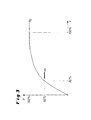
- Zum Befüllen steht ein relativ hoher Druck im Formluft-Tank mit ausreichendem Tankvolumen an. Der gewünschte und deutlich geringere Formluftdruck im Werkzeug ist daher schnell aufgebaut, da der steile exponentielle Anstieg des Füllens infolge einer entsprechend günstigen Zeitkonstante genutzt werden kann. Erst bei höheren Fülldrücken, also wenn die Druckdifferenz kleiner wird, würde ein langsameres Nachfüllen zutage treten. Das Nachfüllen hat keinen Einfluss auf die Ausformung und die Auskühlung, vorausgesetzt die Formluft im Werkzeug wirkt schnell.
- Da abweichend vom relativ hohen Tankdruck nur mit einem geringeren, begrenzten Werkzeug-Formluft-Druck gearbeitet wird, muss vorteilhaft nur der kleinere Druck auch wieder entlüftet werden. Die Entlüftungszeit ist somit geringer. Wertvolle Druckluft wird gespart. Das Verfahren ist für Artikel (Becher, Schalen) mit beliebigen Formen anwendbar.
- Es hat sich gezeigt, dass mit der erfindungsgemäßen Vorgehensweise Formluftfüllzeiten erreichbar sind, die mit der Luftspartechnik vergleichbar sind. Auch die Entlüftungszeiten sind mit der Luftspartechnik vergleichbar. Es ist eine Drucklufteinsparung im Vergleich mit vorbekannten Werkzeugen von 25 % bis 50 % möglich.
- In der Zeichnung ist ein Ausführungsbeispiel der Erfindung dargestellt. Es zeigen:
- Fig. 1
- schematisch eine Thermoformmaschine, die mit einem Formluft-Tank verbunden ist;
- Fig. 2
- einen Teil des Werkzeugs der Thermoformmaschine mit einem Vorstrecker; und
- Fig. 3
- schematisch den Verlauf des Drucks der ins Werkzeug eingegebenen Formluft als Funktion der Zeit.
- In
Fig. 1 ist schematisch eine Thermoformmaschine 1 skizziert, die ein zweiteiliges Werkzeug 2 aufweist. Wie eingangs beschrieben, wird bei der Herstellung von Artikeln im Thermoformprozess Formluft eingesetzt, die in einem Formluft-Tank 3 bevorratet wird. - Der Thermoform-Prozess sieht prinzipiell folgende Schritte vor:
- Zunächst wird ein Folienabschnitt aufgeheizt. Dieser wird in die Formstation, d. h. in den Werkzeugbereich transportiert. Anschließend wird das Werkzeug 2 geschossen. Hierbei klemmt ein Niederhalter die Folie ein. Die Vorstrecker - s. hierzu Position 11 in
Fig. 2 - fahren in die Folie ein. Die Formkavität wird dann mit Formluft aus dem Formluft-Tank 3 gefüllt. Die Folie wird an die Formwandung gedrückt und kühlt aus; gleichzeitig fahren die Vorstrecker nach oben. Das Werkzeug 2 kann anschließend entlüftet und das fertige Formteil nach der Werkzeugöffnung entnommen werden. - Die Formluft wird im Formluft-Tank unter einem Druck p0 gehalten. Dieser Druck beträgt typischerweise zwischen 6 und 8 bar und sollte möglichst konstant gehalten werden. Die Befüllung des Formluft-Tanks 3 erfolgt über das Druckluft-Leitungsnetz des Gebäudes, in dem die Thermoformmaschine 1 aufgestellt ist. Angedeutet ist eine Speiseleitung 7, mit der Luft aus dem Druckluftnetz in den Formluft-Tank 3 eingegeben wird. Dabei sorgt ein Druckminderer 8 für einen gleichbleibenden Speisedruck.
- Im Werkzeug 2 wird ein Formluft-Druck p1 angestrebt, der wesentlich unter dem Formluft-Druck p0 im Formluft-Tank 3 liegt. Typisch sind 2,5 bis 4 bar, die für den vorliegenden Zweck absolut ausreichend sind. Das Eingeben und Ablassen der Formluft in das und aus dem Werkzeug 2 wird dabei von zwei Ventilen 4 und 5 gesteuert.
- Das erste Ventil 4 liegt in einer Gasleitung, die vom Formluft-Tank 3 ins Werkzeug 2 führt und aus den beiden Teilen 9' und 9" besteht.
- Das zweite Ventil 5 ist über eine Gasleitung 10 mit dem ersten Ventil 4 fluidisch verbunden und mündet seinerseits in die Umgebung U (wobei noch ein Schalldämpfer vor dem Luftaustritt in die Umgebung vorgesehen ist).
- Den Druck in der Gasleitung 9" wird von einem Drucksensor 12 gemessen, der mit einer Steuerungs- oder Regelungseinrichtung 6 verbunden ist. Diese steuert die Ventile 4 und 5.
- In Abhängigkeit der Ansteuerung der Ventile kann zunächst erreicht werden, dass trotz des höheren Drucks p0 im Formluft-Tank 3 im Werkzeug 2 nur ein geringerer Druck p1 aufrecht erhalten wird. Hierzu steuert die Steuerungs- oder Regelungseinrichtung 6 das Ventil 4 in Abhängigkeit des vom Drucksensor 12 ermittelten Drucks entsprechend an.
- Die Ansteuerung der Ventile 4 und 5 hat darüber hinaus die Folge, dass die folgenden tabellarisch angegebenen Modi gefahren werden können:
Ventil 4 Ventil 5 Funktion offen geschlossen Werkzeug füllen geschlossen geschlossen Formdruck halten geschlossen offen Werkzeug entlüften - Der Druck im Formluft-Tank p0 ist also stets größer als der Formluft-Druck p1 im Werkzeug 2. Das Werkzeug bzw. die Speiseleitung ist mit dem Drucksensor 12 ausgestattet. Mittels der Maschinensteuerung 6 wird beim Erreichen des voreingestellten Formdrucks die Formluftzufuhr gesperrt. Während der voreingestellten Kühlzeit verbleibt dieser Druck in der Werkzeugform, um anschließend entlüftet zu werden. Der Formprozess ist dann beendet, das Werkzeug öffnet nach einer voreingestellten Entlüftungszeit.
- Während der Formluft-Tank 3 mit dem üblichen Werksdruck (meist zwischen 6 und 8 bar) gespeist wird, wird der Werkzeug-Druck p1 über die Steuerung parametriert. Die Höhe des Drucks p1 liegt meist deutlich unter dem Druck p0. Wie erwähnt gilt, dass ein Druck zwischen 2,5 und 4 bar meist ausreichend ist. Entscheidend für die Ausformung ist nur, dass eine Mindestdruckgröße möglichst schnell in die Form gebracht wird, weil dann noch die Verformbarkeit der Folie mit annähernd optimalem Temperaturprofil gegeben ist.
- Dies wird durch die Druckdifferenz zwischen Formluft-Tank und Werkzeug erreicht. Da das Befüllen nach einer Exponential-Funktion verläuft, wird ca. 65 % des Tankdruckes bereits nach ca. 20 % der Zeit für das - nach dem Stand der Technik üblichen - Befüllen mit Tankdruck erreicht. Dies ist in
Fig. 3 schematisch dargestellt. - Aufgrund des im Verhältnis zum Tank-Drucks p0 kleinen Formdrucks p1 ist die Entlüftungszeit kürzer, da nur ein kleineres Druckpotential in die Atmosphäre, d. h. in die Umgebung U, entlüftet werden muss.
- Folgendes Beispiel sei angeführt:
- Bei den vorbekannten Verfahren ist vorgesehen, dass das Werkzeug mit dem Druck im Formluft-Tank befüllt wird. Die hier eingesetzten Ventile haben generell zwei mögliche Stellungen: Zum einen kann in der einen Stellung das Befüllen des Werkzeugs erfolgen, wobei Formluft-Tank und Werkzeug miteinander verbunden werden; zum anderen ist in der anderen Stellung der Tank geschlossen und das Werkzeug geöffnet, d. h. es kann entlüftet werden. Demgemäß liegt beispielsweise bei einem Tankdruck von 6 bar auch ein Formdruck von 6 bar an. Demgemäß muss dann auch der Druck von 6 bar entlüftet werden.
- Die vorliegende Erfindung erlaubt und sieht indes vor, das Werkzeug nur mit einem anteiligen Tankdruck zu füllen, d. h. nur mit einem Teil des Druckniveaus, wie es im Formluft-Tank anliegt. Hierbei sind mehrfach strömungsoptimierte Werkzeugeinlässe wie ggf. mehrere Tanks vorgesehen.
- Das Ventil bzw. die Ventile bzw. Ventilkombinationen haben drei mögliche Funktions-Stellungen (s. obige Tabelle):
- Zunächst ist es in einer ersten Stellung möglich, das Werkzeug zu befüllen, wozu der Formluft-Tank ünd das Werkzeug fluidisch miteinander verbunden werden.
- Dann ist es in einer zweiten Stellung möglich, die Anbindung an den Tank zu schließen und das Werkzeug geschlossen zu halten. In dieser Stellung wird also der Formdruck im Werkzeug aufrechterhalten.
- In einer dritten Stellung ist es schließlich möglich, bei geschlossenem Tank das Werkzeug zu öffnen, d. h. den Druck im Werkzeug zu entlüften.
- Liegt im Tank beispielsweise ein Druck von 8 bar vor, kann mit einem Werkzeugdruck von beispielsweise nur 4 bar gearbeitet werden; somit muss auch nur dieser geringere Druck entlüftet werden.
- Für den Thermoformprozess stehen beispielsweise zwei alternative Steuerungsmöglichkeiten zur Verfügung. Erstens ist es in bevorzugter, für den Anwender einfacher Weise möglich, bei Erreichen des gewünschten bzw. benötigten Drucks durch entsprechende Ventilbetätigung den Druck nicht über das gewünschte Niveau ansteigen zu lassen. Es wird somit der gewünschte Werkzeug-Formdruck parametriert.
- Zweitens kann das Umschalten zwischen Befüllen und Halten nach einer definierten vorgegebenen Zeit erfolgen, die empirisch und artikelspezifisch ermittelt werden kann. Möglich ist es dabei auch, dass der gewünschte bzw. benötigte Druck der Druckwerterfassung mit dem Zeitglied abgeglichen wird. Hierbei wird die Befüllzeit parametriert, was sich dann empfiehlt, wenn der wie vorstehend beschrieben parametrierte Druck nicht mit dem Druck im Formwerkzeug übereinstimmen sollte.
-
- 1
- Thermoformmaschine
- 2
- Werkzeug
- 3
- Formluft-Tank
- 4
- erstes Ventil
- 5
- zweites Ventil
- 6
- Steuerungs- oder Regelungseinrichtung
- 7
- Speiseleitung für den Formluft-Tank
- 8
- Druckminderer
- 9'
- Teil der Gasleitung zwischen Formluft-Tank und Werkzeug
- 9"
- Teil der Gasleitung zwischen Formluft-Tank und Werkzeug
- 10
- Gasleitung
- 11
- Vorstrecker
- 12
- Drucksensor
- U
- Umgebung
- p0
- Druck im Formluft-Tank
- p1
- Druck der Formluft im Werkzeug
Claims (10)
- Verfahren zum Betreiben einer Thermoformmaschine (1) zum Formen von Artikeln aus Kunststoff, wobei die Thermoformmaschine (1) ein mindestens zweiteiliges Werkzeug (2) umfasst sowie mindestens einen Formluft-Tank (3), in dem Formluft unter einem Druck (p0) gehalten wird, wobei zum Ausformen der Artikel Formluft aus dem Formluft-Tank (3) ins Werkzeug (2) eingegeben wird,
dadurch gekennzeichnet, dass
die Formluft in gesteuerter oder geregelter Weise so in das Werkzeug (2) eingegeben wird, dass der Druck der Formluft (p1) im Werkzeug (2) unter dem Druck (p0) im Formluft-Tank (3) liegt. - Verfahren nach Anspruch 1, dadurch gekennzeichnet, dass der Druck der Formluft (p1) im Werkzeug (2) oder vor dem Werkzeug (2) gemessen wird, wobei in Abhängigkeit des gemessenen Drucks (p1) mindestens ein Ventil (4, 5) von einer Steuerungs- oder Regelungseinrichtung (6) betätigt wird, so dass sich ein vorgegebener Druck (p1) einstellt.
- Verfahren nach Anspruch 1 oder 2, dadurch gekennzeichnet, dass der Formluft-Tank (3) über eine Speiseleitung (7) mit Druckluft versorgt wird, wobei die Speiseleitung (7) vorzugsweise Bestandteil einer Druckluftversorgungsanlage für ein Gebäude oder Gebäudeteil ist.
- Verfahren nach Anspruch 3, dadurch gekennzeichnet, dass im Bereich der Speiseleitung (7) und vor dem Formluft-Tank (3) ein Druckminderer (8) angeordnet ist, mit dem der Druck (p0) im Formluft-Tank (3) auf einem definierten Wert gehalten wird.
- Verfahren nach einem der Ansprüche 1 bis 5, dadurch gekennzeichnet, dass der Druck der Formluft (p1) im Werkzeug (2) stets auf einem Niveau gehalten wird, das maximal 75 % des Drucks (p0) im Formluft-Tank (3), vorzugsweise maximal 67 % des Drucks (p0) im Formluft-Tank (3), beträgt.
- Thermoformmaschine (1) zum Formen von Artikeln aus Kunststoff, wobei diese ein mindestens zweiteiliges Werkzeug (2) sowie einen Formluft-Tank (3) umfasst, in dem Formluft unter einem Druck (p0) gehalten wird, insbesondere zur Durchführung des Verfahrens nach einem der Ansprüche 1 bis 5,
dadurch gekennzeichnet, dass
in einer Gasleitung (9', 9") zwischen dem Formluft-Tank (3) und dem Werkzeug (2) mindestens ein Ventil (4, 5) angeordnet ist, wobei das mindestens eine Ventil (4, 5) drei unterschiedliche Modi erlaubt, nämlich- zum Befüllen des Werkzeugs (2) mit Formluft aus dem Formluft-Tank (3) die Herstellung einer fluidischen Verbindung zwischen dem Formluft-Tank (3) und dem Werkzeug (2);- zum Halten des Drucks der Formluft im Werkzeug (2) eine fluidische Unterbrechung der ins Werkzeug (2) führenden Gasleitung (9");- zum Entlüften des Drucks der Formluft aus dem Werkzeug (2) die Herstellung einer fluidischen Verbindung der ins Werkzeug (2) führenden Gasleitung (9") zur Umgebung, wobei gleichzeitig die vom Formluft-Tank (3) kommende Gasleitung (9') fluidisch unterbrochen ist. - Thermoformmaschine nach Anspruch 6, dadurch gekennzeichnet, dass zwei Ventile (4, 5) vorhanden sind, wobei ein erstes Ventil (4) in der Gasleitung (9', 9") angeordnet ist, die sich zwischen dem Formluft-Tank (3) und dem Werkzeug (2) erstreckt, und wobei ein zweites Ventil (5) zwischen einer vom ersten Ventil (4) kommenden Gasleitung (10) und der Umgebung (U) angeordnet ist.
- Thermoformmaschine nach Anspruch 6 oder 7, dadurch gekennzeichnet, dass mindestens eines der Ventile (4, 5) ein 3/2-Wege-Ventil oder ein 5/3-Wege-Ventil ist.
- Thermoformmaschine nach Anspruch 6 oder 7, dadurch gekennzeichnet, dass mindestens eines der Ventile (4, 5) ein Proportionalventil ist.
- Thermoformmaschine nach einem der Ansprüche 6 bis 9, dadurch gekennzeichnet, dass im Werkzeug (2) mindestens ein mechanischer Vorstrecker (11) angeordnet ist.
Priority Applications (1)
| Application Number | Priority Date | Filing Date | Title |
|---|---|---|---|
| EP13004708.7A EP2853375B1 (de) | 2013-09-27 | 2013-09-27 | Verfahren zum Betreiben einer Thermoformmaschine und Thermoformmaschine |
Applications Claiming Priority (1)
| Application Number | Priority Date | Filing Date | Title |
|---|---|---|---|
| EP13004708.7A EP2853375B1 (de) | 2013-09-27 | 2013-09-27 | Verfahren zum Betreiben einer Thermoformmaschine und Thermoformmaschine |
Publications (2)
| Publication Number | Publication Date |
|---|---|
| EP2853375A1 true EP2853375A1 (de) | 2015-04-01 |
| EP2853375B1 EP2853375B1 (de) | 2018-12-26 |
Family
ID=49322132
Family Applications (1)
| Application Number | Title | Priority Date | Filing Date |
|---|---|---|---|
| EP13004708.7A Active EP2853375B1 (de) | 2013-09-27 | 2013-09-27 | Verfahren zum Betreiben einer Thermoformmaschine und Thermoformmaschine |
Country Status (1)
| Country | Link |
|---|---|
| EP (1) | EP2853375B1 (de) |
Cited By (1)
| Publication number | Priority date | Publication date | Assignee | Title |
|---|---|---|---|---|
| CN118847809A (zh) * | 2024-09-26 | 2024-10-29 | 上海航天设备制造总厂有限公司 | 波纹膜片压制装置及其使用方法 |
Citations (13)
| Publication number | Priority date | Publication date | Assignee | Title |
|---|---|---|---|---|
| DE4340449C2 (de) | 1993-11-27 | 1996-05-23 | Illig Maschinenbau Adolf | Verfahren zum Steuern des Formdruckes zum Druckluftformen eines Artikels aus thermoplastischer Kunststoffolie und Vorrichtung zur Durchführung des Verfahrens |
| EP1103365A1 (de) | 1999-11-24 | 2001-05-30 | Optipack GmbH & Co. KG | Vorrichtung zum Tiefziehen von becherförmigen Körpern |
| DE20116922U1 (de) | 2001-10-15 | 2002-01-24 | Marbach Werkzeugbau GmbH, 74080 Heilbronn | Thermoformwerkzeug |
| DE19726768C2 (de) | 1997-06-24 | 2002-10-24 | Illig Maschinenbau Adolf | Verfahren zum Kühlen eines Behälters aus thermoplastischem Kunststoff und Vorrichtung zur Durchführung des Verfahrens |
| EP1361036A1 (de) * | 2002-05-10 | 2003-11-12 | Adolf Illig Maschinenbau GmbH & Co. KG | Formwerkzeug zum Tiefziehen von Behältern aus thermoplastischem Kunststoff,Stempel mit integriertem Ventil |
| DE10220701A1 (de) | 2002-05-10 | 2003-11-27 | Illig Maschinenbau Adolf | Formwerkzeug zum Tiefziehen von Behältern aus thermoplastischem Kunststoff |
| DE10220700B4 (de) | 2002-05-10 | 2004-04-22 | Adolf Illig Maschinenbau Gmbh & Co.Kg | Formwerkzeug zum Tiefziehen von Behältern aus thermoplastischem Kuststoff |
| DE10326670B3 (de) | 2003-06-13 | 2004-08-26 | Adolf Illig Maschinenbau Gmbh & Co.Kg | Formwerkzeug zum Tiefziehen von Behältern aus thermoplastischem Kunstoff |
| EP1702742B1 (de) | 2005-03-08 | 2008-04-23 | Gabler Thermoform GmbH & Co. KG | Verfahren zum Thermoformen von Kunststofffolien |
| DE102008005625A1 (de) * | 2007-01-29 | 2008-07-31 | Anbeco B.V. | Thermovorrichtung und Verfahren dafür |
| EP2052843A2 (de) | 2007-10-22 | 2009-04-29 | Gabler Thermoform GmbH & Co. KG | Verfahren zum Betreiben einer Vorrichtung zum Herstellen von Formteilen aus einer thermoplastischen Kunststofffolie |
| DE102008013264B3 (de) | 2008-03-08 | 2009-07-09 | Illig Maschinenbau Gmbh & Co. Kg | Verfahren zum Tiefziehen von Behältern aus einer Folienbahn aus thermoplastischem Kunststoff |
| CN202106541U (zh) * | 2011-06-03 | 2012-01-11 | 河北亚大汽车塑料制品有限公司 | 用于热塑性管的蒸汽成型设备 |
-
2013
- 2013-09-27 EP EP13004708.7A patent/EP2853375B1/de active Active
Patent Citations (13)
| Publication number | Priority date | Publication date | Assignee | Title |
|---|---|---|---|---|
| DE4340449C2 (de) | 1993-11-27 | 1996-05-23 | Illig Maschinenbau Adolf | Verfahren zum Steuern des Formdruckes zum Druckluftformen eines Artikels aus thermoplastischer Kunststoffolie und Vorrichtung zur Durchführung des Verfahrens |
| DE19726768C2 (de) | 1997-06-24 | 2002-10-24 | Illig Maschinenbau Adolf | Verfahren zum Kühlen eines Behälters aus thermoplastischem Kunststoff und Vorrichtung zur Durchführung des Verfahrens |
| EP1103365A1 (de) | 1999-11-24 | 2001-05-30 | Optipack GmbH & Co. KG | Vorrichtung zum Tiefziehen von becherförmigen Körpern |
| DE20116922U1 (de) | 2001-10-15 | 2002-01-24 | Marbach Werkzeugbau GmbH, 74080 Heilbronn | Thermoformwerkzeug |
| DE10220700B4 (de) | 2002-05-10 | 2004-04-22 | Adolf Illig Maschinenbau Gmbh & Co.Kg | Formwerkzeug zum Tiefziehen von Behältern aus thermoplastischem Kuststoff |
| DE10220701A1 (de) | 2002-05-10 | 2003-11-27 | Illig Maschinenbau Adolf | Formwerkzeug zum Tiefziehen von Behältern aus thermoplastischem Kunststoff |
| EP1361036A1 (de) * | 2002-05-10 | 2003-11-12 | Adolf Illig Maschinenbau GmbH & Co. KG | Formwerkzeug zum Tiefziehen von Behältern aus thermoplastischem Kunststoff,Stempel mit integriertem Ventil |
| DE10326670B3 (de) | 2003-06-13 | 2004-08-26 | Adolf Illig Maschinenbau Gmbh & Co.Kg | Formwerkzeug zum Tiefziehen von Behältern aus thermoplastischem Kunstoff |
| EP1702742B1 (de) | 2005-03-08 | 2008-04-23 | Gabler Thermoform GmbH & Co. KG | Verfahren zum Thermoformen von Kunststofffolien |
| DE102008005625A1 (de) * | 2007-01-29 | 2008-07-31 | Anbeco B.V. | Thermovorrichtung und Verfahren dafür |
| EP2052843A2 (de) | 2007-10-22 | 2009-04-29 | Gabler Thermoform GmbH & Co. KG | Verfahren zum Betreiben einer Vorrichtung zum Herstellen von Formteilen aus einer thermoplastischen Kunststofffolie |
| DE102008013264B3 (de) | 2008-03-08 | 2009-07-09 | Illig Maschinenbau Gmbh & Co. Kg | Verfahren zum Tiefziehen von Behältern aus einer Folienbahn aus thermoplastischem Kunststoff |
| CN202106541U (zh) * | 2011-06-03 | 2012-01-11 | 河北亚大汽车塑料制品有限公司 | 用于热塑性管的蒸汽成型设备 |
Non-Patent Citations (1)
| Title |
|---|
| DATABASE WPI Week 201210, Derwent World Patents Index; AN 2012-B36678, XP002721265 * |
Cited By (1)
| Publication number | Priority date | Publication date | Assignee | Title |
|---|---|---|---|---|
| CN118847809A (zh) * | 2024-09-26 | 2024-10-29 | 上海航天设备制造总厂有限公司 | 波纹膜片压制装置及其使用方法 |
Also Published As
| Publication number | Publication date |
|---|---|
| EP2853375B1 (de) | 2018-12-26 |
Similar Documents
| Publication | Publication Date | Title |
|---|---|---|
| DE68903647T2 (de) | Vorrichtung und verfahren zum herstellen von gegenstaenden durch superplastische formgebung. | |
| DE3854521T2 (de) | Verfahren zur Regelung einer hydraulischen Presse. | |
| DE102009005921A1 (de) | Verfahren und Vorrichtung zum superplastischen Umformen | |
| EP2468638A1 (de) | Verpackungsmaschine und Verfahren zum Erzeugen einer Vakuumverpackung | |
| DE68913647T2 (de) | Pneumatisches Gesenkpolster. | |
| EP3015248B1 (de) | Verfahren und vorrichtung zum umformen von kunststoffvorformlingen mit querschnittsveränderung eines volumenstroms | |
| WO2012100789A1 (de) | Vakuum-druckgiessmaschine | |
| WO2008080452A1 (de) | Verfahren zur herstellung von behältern | |
| CH661004A5 (de) | Presse. | |
| WO2017037229A1 (de) | Verfahren und vorrichtung zur herstellung von faserverstärkten kunststoffteilen | |
| DE202015104700U1 (de) | Vorrichtung zur Herstellung von faserverstärkten Kunststoffteilen | |
| EP3864301A1 (de) | Bewegungsvorrichtung, reifenhandhabungsvorrichtung und verfahren zum betrieb eines fluidischen aktors | |
| EP3593924B1 (de) | Vorrichtung mit filtermodul zur herstellung von druckgussteilen | |
| DE102007037748B3 (de) | Formwerkzeug und Verfahren zum Tiefziehen von Behältern aus einer erwärmten Folienbahn aus thermoplastischem Kunststoff | |
| EP2853375A1 (de) | Verfahren zum Betreiben einer Thermoformmaschine und Thermoformmaschine | |
| DE102005050868A1 (de) | Druckgesteuertes superplastisches Umformen | |
| EP1625901A1 (de) | Presse mit einer Vorrichtung zur Erfassung einer gegenseitigen Referenzlage von Werkzeugteilen eines Pressenwerkzeuges | |
| EP3941711B1 (de) | Blasventilvorrichtung einer blasvorrichtung | |
| EP3711926B1 (de) | Blasventilvorrichtung einer blasvorrichtung | |
| DE202014000907U1 (de) | Werkzeug, Werkzeugstation und Thermoformanlage | |
| DE112016006715T5 (de) | Vorrichtung, Formaufbau und Verfahren zum Thermoformen eines Produkts aus einem Kunststofffilm | |
| DE102009014090B4 (de) | Verpackungsmaschine und Verpackungsverfahren mit Wiederverwendung von Druckluft | |
| EP1361036A1 (de) | Formwerkzeug zum Tiefziehen von Behältern aus thermoplastischem Kunststoff,Stempel mit integriertem Ventil | |
| DE10329898B4 (de) | Verfahren und Vorrichtung zum Umformen von Blechplatinen | |
| DE4340449C2 (de) | Verfahren zum Steuern des Formdruckes zum Druckluftformen eines Artikels aus thermoplastischer Kunststoffolie und Vorrichtung zur Durchführung des Verfahrens |
Legal Events
| Date | Code | Title | Description |
|---|---|---|---|
| PUAI | Public reference made under article 153(3) epc to a published international application that has entered the european phase |
Free format text: ORIGINAL CODE: 0009012 |
|
| 17P | Request for examination filed |
Effective date: 20130927 |
|
| AK | Designated contracting states |
Kind code of ref document: A1 Designated state(s): AL AT BE BG CH CY CZ DE DK EE ES FI FR GB GR HR HU IE IS IT LI LT LU LV MC MK MT NL NO PL PT RO RS SE SI SK SM TR |
|
| AX | Request for extension of the european patent |
Extension state: BA ME |
|
| R17P | Request for examination filed (corrected) |
Effective date: 20150828 |
|
| RBV | Designated contracting states (corrected) |
Designated state(s): AL AT BE BG CH CY CZ DE DK EE ES FI FR GB GR HR HU IE IS IT LI LT LU LV MC MK MT NL NO PL PT RO RS SE SI SK SM TR |
|
| 17Q | First examination report despatched |
Effective date: 20160429 |
|
| STAA | Information on the status of an ep patent application or granted ep patent |
Free format text: STATUS: EXAMINATION IS IN PROGRESS |
|
| GRAP | Despatch of communication of intention to grant a patent |
Free format text: ORIGINAL CODE: EPIDOSNIGR1 |
|
| STAA | Information on the status of an ep patent application or granted ep patent |
Free format text: STATUS: GRANT OF PATENT IS INTENDED |
|
| RIC1 | Information provided on ipc code assigned before grant |
Ipc: B29C 51/46 20060101AFI20180621BHEP Ipc: B29C 51/04 20060101ALN20180621BHEP |
|
| INTG | Intention to grant announced |
Effective date: 20180712 |
|
| RIC1 | Information provided on ipc code assigned before grant |
Ipc: B29C 51/46 20060101AFI20180703BHEP Ipc: B29C 51/04 20060101ALN20180703BHEP |
|
| GRAS | Grant fee paid |
Free format text: ORIGINAL CODE: EPIDOSNIGR3 |
|
| GRAA | (expected) grant |
Free format text: ORIGINAL CODE: 0009210 |
|
| STAA | Information on the status of an ep patent application or granted ep patent |
Free format text: STATUS: THE PATENT HAS BEEN GRANTED |
|
| AK | Designated contracting states |
Kind code of ref document: B1 Designated state(s): AL AT BE BG CH CY CZ DE DK EE ES FI FR GB GR HR HU IE IS IT LI LT LU LV MC MK MT NL NO PL PT RO RS SE SI SK SM TR |
|
| REG | Reference to a national code |
Ref country code: GB Ref legal event code: FG4D Free format text: NOT ENGLISH |
|
| REG | Reference to a national code |
Ref country code: CH Ref legal event code: EP |
|
| REG | Reference to a national code |
Ref country code: AT Ref legal event code: REF Ref document number: 1080797 Country of ref document: AT Kind code of ref document: T Effective date: 20190115 |
|
| REG | Reference to a national code |
Ref country code: DE Ref legal event code: R096 Ref document number: 502013011876 Country of ref document: DE |
|
| REG | Reference to a national code |
Ref country code: IE Ref legal event code: FG4D Free format text: LANGUAGE OF EP DOCUMENT: GERMAN |
|
| REG | Reference to a national code |
Ref country code: CH Ref legal event code: NV Representative=s name: SCHMAUDER AND PARTNER AG PATENT- UND MARKENANW, CH |
|
| REG | Reference to a national code |
Ref country code: NL Ref legal event code: FP |
|
| PG25 | Lapsed in a contracting state [announced via postgrant information from national office to epo] |
Ref country code: NO Free format text: LAPSE BECAUSE OF FAILURE TO SUBMIT A TRANSLATION OF THE DESCRIPTION OR TO PAY THE FEE WITHIN THE PRESCRIBED TIME-LIMIT Effective date: 20190326 Ref country code: BG Free format text: LAPSE BECAUSE OF FAILURE TO SUBMIT A TRANSLATION OF THE DESCRIPTION OR TO PAY THE FEE WITHIN THE PRESCRIBED TIME-LIMIT Effective date: 20190326 Ref country code: HR Free format text: LAPSE BECAUSE OF FAILURE TO SUBMIT A TRANSLATION OF THE DESCRIPTION OR TO PAY THE FEE WITHIN THE PRESCRIBED TIME-LIMIT Effective date: 20181226 Ref country code: LT Free format text: LAPSE BECAUSE OF FAILURE TO SUBMIT A TRANSLATION OF THE DESCRIPTION OR TO PAY THE FEE WITHIN THE PRESCRIBED TIME-LIMIT Effective date: 20181226 Ref country code: LV Free format text: LAPSE BECAUSE OF FAILURE TO SUBMIT A TRANSLATION OF THE DESCRIPTION OR TO PAY THE FEE WITHIN THE PRESCRIBED TIME-LIMIT Effective date: 20181226 Ref country code: FI Free format text: LAPSE BECAUSE OF FAILURE TO SUBMIT A TRANSLATION OF THE DESCRIPTION OR TO PAY THE FEE WITHIN THE PRESCRIBED TIME-LIMIT Effective date: 20181226 |
|
| REG | Reference to a national code |
Ref country code: LT Ref legal event code: MG4D |
|
| PG25 | Lapsed in a contracting state [announced via postgrant information from national office to epo] |
Ref country code: AL Free format text: LAPSE BECAUSE OF FAILURE TO SUBMIT A TRANSLATION OF THE DESCRIPTION OR TO PAY THE FEE WITHIN THE PRESCRIBED TIME-LIMIT Effective date: 20181226 Ref country code: RS Free format text: LAPSE BECAUSE OF FAILURE TO SUBMIT A TRANSLATION OF THE DESCRIPTION OR TO PAY THE FEE WITHIN THE PRESCRIBED TIME-LIMIT Effective date: 20181226 Ref country code: SE Free format text: LAPSE BECAUSE OF FAILURE TO SUBMIT A TRANSLATION OF THE DESCRIPTION OR TO PAY THE FEE WITHIN THE PRESCRIBED TIME-LIMIT Effective date: 20181226 Ref country code: GR Free format text: LAPSE BECAUSE OF FAILURE TO SUBMIT A TRANSLATION OF THE DESCRIPTION OR TO PAY THE FEE WITHIN THE PRESCRIBED TIME-LIMIT Effective date: 20190327 |
|
| PG25 | Lapsed in a contracting state [announced via postgrant information from national office to epo] |
Ref country code: PL Free format text: LAPSE BECAUSE OF FAILURE TO SUBMIT A TRANSLATION OF THE DESCRIPTION OR TO PAY THE FEE WITHIN THE PRESCRIBED TIME-LIMIT Effective date: 20181226 Ref country code: PT Free format text: LAPSE BECAUSE OF FAILURE TO SUBMIT A TRANSLATION OF THE DESCRIPTION OR TO PAY THE FEE WITHIN THE PRESCRIBED TIME-LIMIT Effective date: 20190426 Ref country code: CZ Free format text: LAPSE BECAUSE OF FAILURE TO SUBMIT A TRANSLATION OF THE DESCRIPTION OR TO PAY THE FEE WITHIN THE PRESCRIBED TIME-LIMIT Effective date: 20181226 Ref country code: ES Free format text: LAPSE BECAUSE OF FAILURE TO SUBMIT A TRANSLATION OF THE DESCRIPTION OR TO PAY THE FEE WITHIN THE PRESCRIBED TIME-LIMIT Effective date: 20181226 |
|
| PG25 | Lapsed in a contracting state [announced via postgrant information from national office to epo] |
Ref country code: IS Free format text: LAPSE BECAUSE OF FAILURE TO SUBMIT A TRANSLATION OF THE DESCRIPTION OR TO PAY THE FEE WITHIN THE PRESCRIBED TIME-LIMIT Effective date: 20190426 Ref country code: SM Free format text: LAPSE BECAUSE OF FAILURE TO SUBMIT A TRANSLATION OF THE DESCRIPTION OR TO PAY THE FEE WITHIN THE PRESCRIBED TIME-LIMIT Effective date: 20181226 Ref country code: RO Free format text: LAPSE BECAUSE OF FAILURE TO SUBMIT A TRANSLATION OF THE DESCRIPTION OR TO PAY THE FEE WITHIN THE PRESCRIBED TIME-LIMIT Effective date: 20181226 Ref country code: SK Free format text: LAPSE BECAUSE OF FAILURE TO SUBMIT A TRANSLATION OF THE DESCRIPTION OR TO PAY THE FEE WITHIN THE PRESCRIBED TIME-LIMIT Effective date: 20181226 Ref country code: EE Free format text: LAPSE BECAUSE OF FAILURE TO SUBMIT A TRANSLATION OF THE DESCRIPTION OR TO PAY THE FEE WITHIN THE PRESCRIBED TIME-LIMIT Effective date: 20181226 |
|
| REG | Reference to a national code |
Ref country code: DE Ref legal event code: R097 Ref document number: 502013011876 Country of ref document: DE |
|
| PG25 | Lapsed in a contracting state [announced via postgrant information from national office to epo] |
Ref country code: DK Free format text: LAPSE BECAUSE OF FAILURE TO SUBMIT A TRANSLATION OF THE DESCRIPTION OR TO PAY THE FEE WITHIN THE PRESCRIBED TIME-LIMIT Effective date: 20181226 |
|
| PLBE | No opposition filed within time limit |
Free format text: ORIGINAL CODE: 0009261 |
|
| STAA | Information on the status of an ep patent application or granted ep patent |
Free format text: STATUS: NO OPPOSITION FILED WITHIN TIME LIMIT |
|
| 26N | No opposition filed |
Effective date: 20190927 |
|
| PGFP | Annual fee paid to national office [announced via postgrant information from national office to epo] |
Ref country code: AT Payment date: 20190919 Year of fee payment: 7 |
|
| PG25 | Lapsed in a contracting state [announced via postgrant information from national office to epo] |
Ref country code: SI Free format text: LAPSE BECAUSE OF FAILURE TO SUBMIT A TRANSLATION OF THE DESCRIPTION OR TO PAY THE FEE WITHIN THE PRESCRIBED TIME-LIMIT Effective date: 20181226 |
|
| PG25 | Lapsed in a contracting state [announced via postgrant information from national office to epo] |
Ref country code: MC Free format text: LAPSE BECAUSE OF FAILURE TO SUBMIT A TRANSLATION OF THE DESCRIPTION OR TO PAY THE FEE WITHIN THE PRESCRIBED TIME-LIMIT Effective date: 20181226 |
|
| PG25 | Lapsed in a contracting state [announced via postgrant information from national office to epo] |
Ref country code: LU Free format text: LAPSE BECAUSE OF NON-PAYMENT OF DUE FEES Effective date: 20190927 Ref country code: IE Free format text: LAPSE BECAUSE OF NON-PAYMENT OF DUE FEES Effective date: 20190927 |
|
| REG | Reference to a national code |
Ref country code: BE Ref legal event code: MM Effective date: 20190930 |
|
| PG25 | Lapsed in a contracting state [announced via postgrant information from national office to epo] |
Ref country code: BE Free format text: LAPSE BECAUSE OF NON-PAYMENT OF DUE FEES Effective date: 20190930 |
|
| GBPC | Gb: european patent ceased through non-payment of renewal fee |
Effective date: 20190927 |
|
| PG25 | Lapsed in a contracting state [announced via postgrant information from national office to epo] |
Ref country code: GB Free format text: LAPSE BECAUSE OF NON-PAYMENT OF DUE FEES Effective date: 20190927 Ref country code: FR Free format text: LAPSE BECAUSE OF NON-PAYMENT OF DUE FEES Effective date: 20190930 |
|
| REG | Reference to a national code |
Ref country code: AT Ref legal event code: MM01 Ref document number: 1080797 Country of ref document: AT Kind code of ref document: T Effective date: 20200927 |
|
| PG25 | Lapsed in a contracting state [announced via postgrant information from national office to epo] |
Ref country code: CY Free format text: LAPSE BECAUSE OF FAILURE TO SUBMIT A TRANSLATION OF THE DESCRIPTION OR TO PAY THE FEE WITHIN THE PRESCRIBED TIME-LIMIT Effective date: 20181226 |
|
| PG25 | Lapsed in a contracting state [announced via postgrant information from national office to epo] |
Ref country code: MT Free format text: LAPSE BECAUSE OF FAILURE TO SUBMIT A TRANSLATION OF THE DESCRIPTION OR TO PAY THE FEE WITHIN THE PRESCRIBED TIME-LIMIT Effective date: 20181226 Ref country code: HU Free format text: LAPSE BECAUSE OF FAILURE TO SUBMIT A TRANSLATION OF THE DESCRIPTION OR TO PAY THE FEE WITHIN THE PRESCRIBED TIME-LIMIT; INVALID AB INITIO Effective date: 20130927 |
|
| PG25 | Lapsed in a contracting state [announced via postgrant information from national office to epo] |
Ref country code: AT Free format text: LAPSE BECAUSE OF NON-PAYMENT OF DUE FEES Effective date: 20200927 |
|
| PG25 | Lapsed in a contracting state [announced via postgrant information from national office to epo] |
Ref country code: MK Free format text: LAPSE BECAUSE OF FAILURE TO SUBMIT A TRANSLATION OF THE DESCRIPTION OR TO PAY THE FEE WITHIN THE PRESCRIBED TIME-LIMIT Effective date: 20181226 |
|
| P01 | Opt-out of the competence of the unified patent court (upc) registered |
Effective date: 20230517 |
|
| PGFP | Annual fee paid to national office [announced via postgrant information from national office to epo] |
Ref country code: NL Payment date: 20240219 Year of fee payment: 11 |
|
| PGFP | Annual fee paid to national office [announced via postgrant information from national office to epo] |
Ref country code: TR Payment date: 20240219 Year of fee payment: 11 Ref country code: IT Payment date: 20240228 Year of fee payment: 11 |
|
| PGFP | Annual fee paid to national office [announced via postgrant information from national office to epo] |
Ref country code: CH Payment date: 20250305 Year of fee payment: 12 |
|
| REG | Reference to a national code |
Ref country code: NL Ref legal event code: MM Effective date: 20241001 |
|
| PG25 | Lapsed in a contracting state [announced via postgrant information from national office to epo] |
Ref country code: NL Free format text: LAPSE BECAUSE OF NON-PAYMENT OF DUE FEES Effective date: 20241001 |
|
| PG25 | Lapsed in a contracting state [announced via postgrant information from national office to epo] |
Ref country code: IT Free format text: LAPSE BECAUSE OF NON-PAYMENT OF DUE FEES Effective date: 20240927 |
|
| REG | Reference to a national code |
Ref country code: CH Ref legal event code: U11 Free format text: ST27 STATUS EVENT CODE: U-0-0-U10-U11 (AS PROVIDED BY THE NATIONAL OFFICE) Effective date: 20260217 |
|
| PGFP | Annual fee paid to national office [announced via postgrant information from national office to epo] |
Ref country code: DE Payment date: 20260218 Year of fee payment: 13 |