EP2857493A1 - Agitateur pour un récipient, récipient et procédé de montage d'un agitateur dans un récipient - Google Patents
Agitateur pour un récipient, récipient et procédé de montage d'un agitateur dans un récipient Download PDFInfo
- Publication number
- EP2857493A1 EP2857493A1 EP14186392.8A EP14186392A EP2857493A1 EP 2857493 A1 EP2857493 A1 EP 2857493A1 EP 14186392 A EP14186392 A EP 14186392A EP 2857493 A1 EP2857493 A1 EP 2857493A1
- Authority
- EP
- European Patent Office
- Prior art keywords
- agitator
- container
- shaft
- bearing
- fermenter
- Prior art date
- Legal status (The legal status is an assumption and is not a legal conclusion. Google has not performed a legal analysis and makes no representation as to the accuracy of the status listed.)
- Granted
Links
Images


Classifications
-
- B—PERFORMING OPERATIONS; TRANSPORTING
- B01—PHYSICAL OR CHEMICAL PROCESSES OR APPARATUS IN GENERAL
- B01F—MIXING, e.g. DISSOLVING, EMULSIFYING OR DISPERSING
- B01F27/00—Mixers with rotary stirring devices in fixed receptacles; Kneaders
- B01F27/21—Mixers with rotary stirring devices in fixed receptacles; Kneaders characterised by their rotating shafts
- B01F27/213—Mixers with rotary stirring devices in fixed receptacles; Kneaders characterised by their rotating shafts characterised by the connection with the drive
-
- C—CHEMISTRY; METALLURGY
- C12—BIOCHEMISTRY; BEER; SPIRITS; WINE; VINEGAR; MICROBIOLOGY; ENZYMOLOGY; MUTATION OR GENETIC ENGINEERING
- C12M—APPARATUS FOR ENZYMOLOGY OR MICROBIOLOGY; APPARATUS FOR CULTURING MICROORGANISMS FOR PRODUCING BIOMASS, FOR GROWING CELLS OR FOR OBTAINING FERMENTATION OR METABOLIC PRODUCTS, i.e. BIOREACTORS OR FERMENTERS
- C12M21/00—Bioreactors or fermenters specially adapted for specific uses
- C12M21/04—Bioreactors or fermenters specially adapted for specific uses for producing gas, e.g. biogas
-
- C—CHEMISTRY; METALLURGY
- C12—BIOCHEMISTRY; BEER; SPIRITS; WINE; VINEGAR; MICROBIOLOGY; ENZYMOLOGY; MUTATION OR GENETIC ENGINEERING
- C12M—APPARATUS FOR ENZYMOLOGY OR MICROBIOLOGY; APPARATUS FOR CULTURING MICROORGANISMS FOR PRODUCING BIOMASS, FOR GROWING CELLS OR FOR OBTAINING FERMENTATION OR METABOLIC PRODUCTS, i.e. BIOREACTORS OR FERMENTERS
- C12M23/00—Constructional details, e.g. recesses, hinges
- C12M23/02—Form or structure of the vessel
-
- C—CHEMISTRY; METALLURGY
- C12—BIOCHEMISTRY; BEER; SPIRITS; WINE; VINEGAR; MICROBIOLOGY; ENZYMOLOGY; MUTATION OR GENETIC ENGINEERING
- C12M—APPARATUS FOR ENZYMOLOGY OR MICROBIOLOGY; APPARATUS FOR CULTURING MICROORGANISMS FOR PRODUCING BIOMASS, FOR GROWING CELLS OR FOR OBTAINING FERMENTATION OR METABOLIC PRODUCTS, i.e. BIOREACTORS OR FERMENTERS
- C12M23/00—Constructional details, e.g. recesses, hinges
- C12M23/34—Internal compartments or partitions
-
- C—CHEMISTRY; METALLURGY
- C12—BIOCHEMISTRY; BEER; SPIRITS; WINE; VINEGAR; MICROBIOLOGY; ENZYMOLOGY; MUTATION OR GENETIC ENGINEERING
- C12M—APPARATUS FOR ENZYMOLOGY OR MICROBIOLOGY; APPARATUS FOR CULTURING MICROORGANISMS FOR PRODUCING BIOMASS, FOR GROWING CELLS OR FOR OBTAINING FERMENTATION OR METABOLIC PRODUCTS, i.e. BIOREACTORS OR FERMENTERS
- C12M23/00—Constructional details, e.g. recesses, hinges
- C12M23/48—Holding appliances; Racks; Supports
-
- C—CHEMISTRY; METALLURGY
- C12—BIOCHEMISTRY; BEER; SPIRITS; WINE; VINEGAR; MICROBIOLOGY; ENZYMOLOGY; MUTATION OR GENETIC ENGINEERING
- C12M—APPARATUS FOR ENZYMOLOGY OR MICROBIOLOGY; APPARATUS FOR CULTURING MICROORGANISMS FOR PRODUCING BIOMASS, FOR GROWING CELLS OR FOR OBTAINING FERMENTATION OR METABOLIC PRODUCTS, i.e. BIOREACTORS OR FERMENTERS
- C12M27/00—Means for mixing, agitating or circulating fluids in the vessel
- C12M27/02—Stirrer or mobile mixing elements
- C12M27/06—Stirrer or mobile mixing elements with horizontal or inclined stirrer shaft or axis
-
- Y—GENERAL TAGGING OF NEW TECHNOLOGICAL DEVELOPMENTS; GENERAL TAGGING OF CROSS-SECTIONAL TECHNOLOGIES SPANNING OVER SEVERAL SECTIONS OF THE IPC; TECHNICAL SUBJECTS COVERED BY FORMER USPC CROSS-REFERENCE ART COLLECTIONS [XRACs] AND DIGESTS
- Y10—TECHNICAL SUBJECTS COVERED BY FORMER USPC
- Y10T—TECHNICAL SUBJECTS COVERED BY FORMER US CLASSIFICATION
- Y10T29/00—Metal working
- Y10T29/49—Method of mechanical manufacture
- Y10T29/49826—Assembling or joining
Definitions
- the present invention relates to an agitator for use in a container, comprising a rotatable shaft, a drive device, by means of which the shaft is driven, and at least one arranged on the shaft agitating element, which is rotatable together with the shaft, wherein the shaft is connected thereto Bearing device which is arranged in an end region of the shaft facing away from the drive device, wherein the shaft is rotatable about its longitudinal axis relative to the bearing device, wherein by means of the bearing means the agitator is storable in a receptacle connected to the container, wherein the bearing means by means of a sliding bearing or roller bearing along a guide device is movable, wherein the sliding bearing comprises at least one sliding surface which is movable on a corresponding sliding surface of the guide means or the roller bearing comprises at least one roller, which on a rolling surface d he guide device is unrolled.
- the invention relates to a container, in particular a fermenter for the fermentation of biodegradable substances, comprising at least one bottom plate, at least one wall and at least one ceiling device, wherein means of the bottom plate, the wall and the ceiling means an interior of the container is enclosed substantially gas-tight, wherein the container has at least one agitator by means of which substances located in the interior of the container are stirrable, wherein the ceiling device is formed by at least two ceiling units, namely at least one plate unit and at least one membrane unit, wherein the plate unit of a rigid member and the membrane unit of a flexible membrane are formed, wherein the plate unit and the membrane unit in areas where they abut, are connected to each other in a substantially gas-tight manner.
- such a container may have a receiving device connected to the base plate, by means of which a bearing device of the agitator, which is arranged in an end plate of the container facing the end of a shaft of the agitator, is receivable and also optionally have a guide means by which the storage device of Agitator in the course before its transfer from a mounting position into an installation position on the receiving device is feasible, wherein the receiving device is disposed at one end of the guide means and determines the installation position of the agitator, in which it blocks an unintentional movement of the bearing means.
- Stirrers and containers in particular fermenters of the type described above are known for some time according to the prior art and are mainly used in the field of biogas plants, which are used to generate renewable energy.
- Agitators of the type described above are subject to a certain normal wear during operation. This concerns primarily the bearings and the gear of the agitators. Depending on the quality of the agitator, it sooner or later comes to its failure due to a failure of at least one of the wearing parts, unless it already takes place before a precautionary replacement of wearing parts. In the event of a failure, the wear parts must then be replaced in order to put the stirrer back into operation. For fermenters with multiple agitators, a temporary failure of a single agitator can sometimes be tolerable for a period of time. Due to the sinking circulation of the substrate located in the fermenter, however, the deliberate biological decomposition process wears off, which ultimately leads to a reduction in the conversion and the energy output of the biogas plant. By such losses, the Economically reduced biogas plant economy. A long-term failure of a stirrer or even more agitators is therefore not acceptable.
- the known construction is disadvantageous insofar as it necessarily requires a vertical operating position of the agitator shaft and on the other hand compellingly requires such a fermenter whose ceiling device is formed by a rigid concrete ceiling. This serves as a frame construction for receiving the agitators, which are lowered from the top into the fermenter.
- Such a ceiling construction is disadvantageous in that it requires on the one hand a high planning effort and must be separately calculated and planned for each fermenter of each project and on the other delayed the construction of the fermenter, since such a ceiling construction in the production is relatively expensive.
- Such fermenters with membrane seals are clearly beneficial.
- Such membranes are gas-tight connected to the peripheral walls of the fermenter and then bulge due to the forming in the interior of the fermenter biogas to the outside and to some extent form a kind of tent roof over the fermenter.
- the establishment of such a ceiling device in the form of a flexible membrane is thus considerably faster and cheaper possible.
- the planning costs described in essential parts is an assignment vertically oriented agitators in such systems not possible because a storage of the agitator at its upper end without a frame construction can not be done easily.
- the membrane itself is not suitable to absorb occurring bearing forces.
- fermenters sealed with such a membrane are typically operated with agitators or other devices suitable for circulating the substrate, which are inserted laterally through the wall into the fermentor.
- agitators or other devices suitable for circulating the substrate which are inserted laterally through the wall into the fermentor.
- both oblique stirrers and so-called "stick mixer” can be used.
- Oblique stirrers are for example the writings DE 20 2004 004 101 U1 and WO 2007/110775 A2 removable. These show stirrers, which are guided laterally through the walls of the respective fermenter from the interior to the outside and are stored in or on the walls.
- the systems shown have the disadvantage that the fermenter can only be filled to a relatively small filling level, which ends in each case below the lateral mounting opening in the wall of the fermenter. The height of the fermenter can therefore only partially be exploited.
- a heated agitator for fermentation tank which is provided for entry of both mechanical and thermal energy in a fermentation tank.
- the known agitator has a heatable stirrer shaft and heat conduction surfaces attached to the stirrer shaft, to which agitator blades are in turn arranged.
- the shaft axis is inclined relative to the vertical by an angle of approximately 45 °.
- the shaft bearing is housed in a container-fixed bearing foot (so-called mounting bracket).
- the angle of inclination of the lower container-fixed storage device is adjustable in the course of assembly with an empty fermentation tank. After wear of the bearing, the container should be emptied in order to replace the bearing device.
- the DE 82 12 809 U1 discloses a stirring device in which a bottomed storage device is provided.
- the object of the invention described in this document is to achieve a flow direction in the substrate to be contacted, which is aligned parallel to the agitator shaft. If damage to the bottom-side storage facility, so the container is to be emptied in order to make an exchange of the storage facility can.
- Object of the present invention is therefore to provide a stirrer and a container, in particular fermenter, which allow the stirrer as easy as possible to change during operation and to use a storage that allows the simplest possible construction of the ceiling device of the container.
- the underlying object is achieved on the basis of an agitator of the type described above according to the invention that an angle between the longitudinal axis of the shaft and the vertical increases during the transfer of the agitator from a mounting position to an installed position and preferably in the installed position between 5 ° and 60 °, more preferably between 10 ° and 50 °.
- this bearing comprises an upper end of the agitator, which must be fastened to remove operating forces of the agitator.
- This load transfer is all the more complicated to accomplish, the farther the upper end of a respective agitator to be stored is arranged away from the wall of the associated fermenter. This results from the fact that the forces to be removed have to be removed over even more distances up to the wall of the respective fermenter. Consequently, there is the desire to arrange the upper end of the agitator as close to the wall, possibly even "in" the wall, that is, to introduce the bearing forces directly into the wall.
- the agitator according to the invention results from the above consideration of the desire to position it in its installation or operating position in which it is completely mounted in a respective fermenter as possible at a certain minimum distance to the wall of the fermenter, so that at least one Stirrer of the agitator has enough distance to the respective nearest wall of the fermenter and there is no risk to beat against the same.
- the solution according to the invention is based on the idea of initially inserting the agitator in the container, in particular the fermenter, as close as possible to the wall (and as far as possible hanging on a lifting tool and preferably in the vertical direction) during its assembly.
- the mounting position is reached as soon as the lower end of the agitator shaft with the sliding or rolling bearing located there in the course of lowering the guide means touches and then only the lower end of the agitator as far away from the wall to move, while the upper end of the agitator at least remains near the wall.
- the solution according to the invention consequently includes an agitator oriented obliquely in its final operating position, whose longitudinal axis of the shaft is inclined relative to a vertical.
- the energy required by the lower end of the agitator shaft may be "generated” by conversion from potential energy when the guide means is made to slope down towards the receiver.
- a stirring effect achieved by means of the at least one stirring element is also present outside the edge region of the fermenter, since the agitator, due to its oblique position, at least partially extends in the direction of the middle region of the fermenter and can bring about a stirring of the substrate here.
- a ceiling device which is provided for receiving the upper end of the agitator, must be rigid only in an edge region of the fermenter, wherein such a rigid ceiling unit does not have to extend to a considerable extent from the wall in the direction of the central region of the fermenter.
- a remaining part of the ceiling device can meanwhile be formed by the flexible ceiling unit, in particular a flexible membrane.
- the rigid ceiling unit can be almost completely eliminated, with only optionally a portion must remain, which is used for assembly or disassembly of the agitator.
- high fermenters typically higher than 8 m
- the ceiling device of the fermenter can be formed accordingly almost completely by a flexible membrane.
- the movement of the agitator directed away from the wall of the fermenter during the assembly process takes place according to the invention by means of the slide bearing or the roller bearing of the bearing device.
- the sliding device has a sliding surface, which is particularly well suited to slide sliding friction on a corresponding sliding surface.
- the sliding surface should be as smooth as possible.
- said roller bearing is possible, which has at least one roller, which is suitable to unroll on a corresponding rolling surface.
- a surface of the bottom plate of the fermenter is conceivable.
- the fermenter therefore advantageously has a guide device, by means of which the sliding surface of the slide bearing or the roller of the roller bearing - and thus the bearing device and ultimately the entire agitator - can be guided very easily.
- a guide device by means of which the sliding surface of the slide bearing or the roller of the roller bearing - and thus the bearing device and ultimately the entire agitator - can be guided very easily.
- the aim is to move the bearing device of the agitator by means of the sliding or the roller bearing in an installation position in which the storage device then remains and the agitator can be put into operation.
- the effect of this approach is with the EP 2 064 308 B1 comparable.
- the bearing means by means of sliding or roller bearing "retractable” or “retractable” in a receiving device, wherein the bearing means in the receiving device is then tool-less storable such that bearing forces are ablatable and in particular a torque-tight connection is present.
- the bearing device itself is rotatably mounted, so does not rotate synchronously to the shaft of the agitator, but is stationary.
- the bearing device itself is designed as a shaft-fixed roller bearing (bearing cartridge). Because of the inclined arrangement, it may be necessary to remove upward "lift-off forces" that may result from a touch of the substrate. This is typically done by means of the bearing of the upper end of the agitator, but can also be achieved by means of a blocking device which is arranged on the receiving device of the lower end of the agitator.
- a tool-free "removal" of the bearing device from the receiving device and a subsequent sliding back of the sliding surface or rolling back of the roller on the guide device is advantageously readily possible, so that maintenance or replacement of the agitator can be done without affecting the operation of the biogas plant ,
- a hinge device is particularly advantageous, by means of which an angle of the shaft and at least a portion of the Holding device is included, is changeable.
- Such variability of the orientation of the stirring element relative to the shaft of the agitator allows compensation for an inclination of the agitator, if necessary and / or desired.
- an angling may be advantageous in order to reduce a horizontally measured distance between a connection point of the holding device on the shaft and an edge part of the stirring element furthest away from the shaft, so that the latter does not run the risk of hitting against the wall of the fermenter.
- a running surface of the at least one roller is concave or convex.
- a trained in this way caster is particularly well suited to cooperate with a correspondingly shaped rolling surface to form a partial positive engagement.
- the rolling surface has a convex shape, wherein the convex portion advantageously has the same radius of curvature, as the associated concave shaped roller, which thus conforms with its surface to the rolling surface and due to the appropriate shape of the corresponding parts laterally is stabilized.
- a targeted guidance of the roller is particularly easy in this way possible.
- the roller bearing has a plurality of rollers, each roll on a rolling surface.
- Such rolling can also take place laterally, that is, a contact surface between the roller and the rolling surface can be oriented vertically. Any other orientation, in particular an oblique orientation of the contact surface at an angle of 45 °, is also conceivable.
- the agitator is arranged inclined to a vertical, the vertical and a longitudinal axis of a shaft of the agitator include an angle between 5 ° and 60 °, wherein at least a portion of the at least one plate unit having the mounting opening is aligned perpendicular to the longitudinal axis of the shaft.
- a subdivision into the ceiling unit and membrane unit is provided according to the invention for an agitator, the upper end of which is mounted on an upper side of the container.
- the disk unit is essentially only necessary for assembly or disassembly of the agitator. That is, even in the case of storing the agitator in the wall of the container, ceiling means are usually formed by two separate ceiling units, the plate unit having only the function of providing an "inlet" for the agitator through which the agitator is placed Installation can be lowered into the container. An attachment of the upper end of the agitator then takes place in the wall of the container, for example in an embedded in the wall frame into which the upper end of the agitator can be inserted from above and fastened thereto.
- the ceiling device makes it possible to use the advantages of the membrane unit as far as the operating position of the agitators allows.
- the plate unit is only needed to reliably store the upper end of the agitator or stirrers, that is, to remove the acting bearing forces. Such storage, that is the inclusion of bearing forces, is not possible by means of the membrane unit.
- the subdivision is particularly useful if the plate unit is arranged as close as possible to the wall of the container. This considerably facilitates the load transfer by means of the plate unit into the walls.
- the plate unit is aligned parallel to the bottom plate.
- Such a disk unit is relatively easy to produce.
- the plate unit thereof has at least one mounting opening, through which the agitator can be inserted from an outside of the plate unit from above into the interior of the container.
- Such an opening is particularly well suited to be able to mount the agitator.
- a "lateral docking" of the agitator to the disk unit is conceivable. Nevertheless, on the one hand the load transfer and on the other hand Connecting the membrane unit to the disk unit easier when the agitator is fixed in a mounting hole, which is surrounded by the disk unit.
- the mounting opening it is particularly advantageous if the same is formed rectangular, with a free cross-section of the mounting hole, which remains after insertion of the agitator in the fermenter and connects the interior of the fermenter with the outside of the plate unit, is substantially gas-tight manner .
- the rectangular cross-sectional shape of the mounting opening is advantageous in that it can be kept as small as possible from its surface and still offers enough space for the stirrer to be used.
- an agitator typically has only one stirring element at one point along its shaft. This means that two stirring elements are not arranged at "the same height" of the shaft, that is not directly next to each other.
- the individual stirring elements if several of them are present, typically arranged offset to the adjacent stirring elements by an angle of 180 ° about the shaft of the agitator.
- an offset of 90 ° or any other angle is conceivable, although this is rather atypical.
- the mounting opening is just dimensioned so large that the shaft along with an attached stirring element "just so” fits through. In this case, it is necessary that the agitator is continuously moved laterally during insertion into the fermenter in order to respectively position the next stirring element (if present) relative to the mounting opening in such a way that it fits through the mounting opening and does not collide with the plate unit.
- a pure lateral movement of the agitator when inserted into the fermenter is not sufficient. Instead, in addition, a rotation of the same must take place about the longitudinal axis of the shaft in order to align the respective next stirring element relative to the mounting opening.
- the mounting opening has dimensions that allow insertion of the agitator without this has to be moved to certain positions. However, such a mounting opening would have to be dimensioned significantly larger and thus weaken the disk unit.
- a sealing of the mounting hole is the harder the larger it is selected.
- the agitator is arranged inclined to a vertical, wherein the vertical and a longitudinal axis of a shaft of the agitator include an angle between 5 ° and 30 °, wherein at least a portion of the at least one plate unit, the having the mounting opening, is aligned perpendicular to the longitudinal axis of the shaft.
- the an oblique arrangement makes it possible to move a lower end of the agitator as far as possible in the direction of a central region of the fermenter, to place there and at the same time to leave an upper end as close to the wall of the fermenter.
- a container according to the invention is particularly advantageous when an upper end portion of the agitator facing away from the bottom plate of the container is connected to the plate unit in force-transmitting manner.
- the plate unit acts as a bearing for the top of the agitator and can accommodate corresponding bearing forces.
- the agitator is mounted by means of its bearing device at its lower end.
- the upper end of the agitator is connected directly to the wall of the container in force-transmitting manner, that is mounted in the wall. In this case, the upper end in an operating position of the agitator, in which it is fully assembled, out "laterally" out of the fermenter, namely from a region of the wall of the fermenter.
- the underlying object is basically solved by a guide means by which the bearing means of the agitator in the course of installation of the agitator in the container in the direction of the receiving device is feasible, the Receiving device is arranged at one end of the guide device and determines an installation position of the bearing device in which it blocks an unintentional movement of the bearing device.
- a guide device has already been described above. It is particularly well suited to guide the roller bearing of the agitator in the receiving device, where the bearing means of the agitator can take its installation position.
- an angle between the vertical and a longitudinal axis of the shaft of the agitator increases during the transfer of Hinchrwerks from the mounting position to the mounting position, an angle between the vertical and a longitudinal axis of the shaft of the agitator, so that the agitator in its operating position in which it is fully assembled and can be put into operation, against a Vertical inclined and the vertical and a longitudinal axis of the shaft of the agitator at an angle between 5 ° and 60 °, preferably between 10 ° and 50 °, include.
- the inclination is a consequence of the advantageous storage of the stirrer already described above, the lower end of which as far as possible is located away from the closest wall of the container, while its upper end as close to the nearest wall of the container, possibly even "in” the wall, is arranged.
- An inclination of the agitator in the container according to the invention in the described range results in height dimensions of conventional containers to the desired result.
- the installation of a guide device is independent of the construction of the ceiling device, in particular the question of whether the ceiling device is formed by at least two different ceiling units (plate unit, membrane unit).
- the container according to the invention selbiger nevertheless has both, that is, both a prescribed subdivided ceiling device and a prescribed guide device.
- the container according to the invention is particularly advantageous if the guide device has an elongate sliding unit or an elongate unwinding unit, preferably a running tube, wherein the sliding unit is preferably smooth and the unwinding unit preferably has a concave or convexly shaped rolling surface.
- the guide device is particularly advantageous if, at least in one part of a guide section, it has an angle of inclination to a horizontal of at least 5 °, preferably at least 7.5 °, more preferably at least 10 °.
- that section of the guide device which comprises a sliding surface for the at least one corresponding sliding surface of the plain bearing or a rolling surface for the at least one roller of the roller bearing of the agitator is referred to as the guide section.
- An inclination at least a portion of the guide portion or advantageously the entire guide portion is particularly advantageous in that the agitator can be performed with its sliding or roller bearings particularly simple on such a guide device.
- the receiving device in a horizontal, perpendicular to the at least one wall measured distance of at least 1.5 m, preferably at least 2.0 m, more preferably at least 2.5 m, from the wall of the container arranged away.
- the receiving device is typically connected directly to the bottom plate of the container. Compliance with the minimum distance described means that the bearing device of the agitator is installed in its installed position at least at just such a distance from the wall of the container and thus ensures that a stirring effect of the stirring not only in an edge region of the container, but also in a Central area of the same can develop.
- This method step is already apparent from the above description and illustrates once again that the agitator can be particularly easily used in an edge region of the container, wherein the agitator in a mounting position, that is, before and at the time when the bearing means meets the guide means is oriented substantially perpendicularly and only by the sliding of the sliding surface or the rolling of the bearing roller on the guide means, which leads away from the wall of the container assumes an oblique position. Meanwhile, the upper end of the agitator remains substantially at the same position and is not moved away from the wall of the container in a manner analogous to the lower end. In that regard, there is a rotation of the agitator against the vertical about a pivot point which is located approximately at the upper end of the agitator.
- the method thus makes it possible that a mounting opening for the introduction of the agitator in the interior of the container must be provided only in an edge region thereof, since a movement of the agitator takes place only "in the container", that is using the guide means.
- Such a movement of the upper end of the agitator may be advantageous in some cases, if otherwise to be feared that the at least one stirring element strikes against the wall of the container.
- an expansion of the agitator according to the invention can run exactly the reverse of its installation.
- the agitator is lifted at its upper end, that the bearing device initially dissolves from the receiving device and then "floating" in the substrate is moved, which is due to the weight of the agitator automatically an approximately vertical orientation of the agitator.
- this procedure is conceivable, since the storage facility does not have to be guided in a targeted manner at a specific location in the same way.
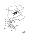
- FIGS. 1 to 5 The embodiment that is in the FIGS. 1 to 5 is shown, comprises both an illustration of an installation of an agitator 1 according to the invention and a representation of its operating position.
- FIG. 1 the agitator 1 according to the invention is shown in its mounting position, the agitator 1 is just installed in a fermenter 2 according to the invention.
- the fermenter 2 comprises a bottom plate 3, a circumferential wall 4, and a two-piece blanket means.
- This ceiling device is formed by two ceiling units, namely on the one hand by a membrane unit 5 and on the other hand by a plate unit 6 .
- the ceiling device is connected substantially gas-tight to the peripheral wall 4 of the fermenter 2 .
- By “essentially” is to be understood that an inner space 7 of the fermenter 2 is sealed against an environment 8 of the fermenter 2 such that an accumulation of gases formed in the fermenter 2 can take place in the inner space 7 .
- the membrane unit 5 and the plate unit 6 are also connected to one another in a substantially gastight manner and together form the dense ceiling device.
- the agitator 1 guide means 9 which is connected to the bottom plate 3 .
- This guide device 9 is formed here by an elongated guide tube 10 , the longitudinal axis is viewed in a plan view of the fermenter 2 viewed perpendicular to the wall 2 . From the in FIG. 1 shown view, it is clear that the guide tube 10 with respect to a horizontal angle of, which is about 8 ° here.
- An orientation of the guide tube 10 is such that a vertically measured distance between the bottom plate 3 of the fermenter 2 and the guide tube 10 decreases with increasing distance from the wall 4 of the fermenter 2 .
- On one of the wall 4 of the fermenter. 2 facing away from the end of the guide tube 10 of the guide device 9 is a likewise associated with the agitator 1 receiving device 11 is arranged, the functionality of which is described in detail in interaction with the agitator 1 below.
- the agitator 1 has a shaft 12 , a drive device 13 , four stirring elements 14 and a bearing device 15 .
- the drive device 13 is arranged on an upper, the bottom plate 3 of the fermenter 2 opposite end of the shaft 12 of the agitator 1 .
- the shaft 12 is rotatable about a longitudinal axis of the shaft 12 to the drive device 13 , wherein the shaft by means of the drive means 13 is rotatable or driven.
- the drive device 13 comprises, in particular, an electric motor and a transmission, the exact design of which is known and therefore not relevant in the context of the present application.
- the bearing means 15 is arranged at one of the drive means 13 opposite lower end of the shaft 12 of the agitator 1 .
- these bearing means 15 is formed of a pivot bearing, which thus is used as a bearing cartridge in the hollow shaft 12 and removed from the fermenter 2 together with the shaft 12th
- a roller bearing 16 is formed, which includes a roller 17 .
- the bearing device 15 is designed to be rotatable relative to the drive device 13 about the longitudinal axis of the shaft 12 relative to the shaft 12 .
- the bearing means 15 and the roller bearing 16 can be used to rotatably support the lower end of the agitator 1 in cooperation with the corresponding receiving device 11 , but this does not block a rotation of the shaft 12 , ie that the bearing means 15 with an outer part in the receiving device 11 is supported and thus 12 stands still during rotation of the shaft, while an inner part of the bearing means 15 rotates together with the shaft 12 about its longitudinal axis.
- FIG. 1 shows that the agitator 1 is lowered in the course of its incorporation into the fermenter 2 through a mounting opening 18 of the plate unit 6 from the environment 8 in the interior 7 of the fermenter 2 .
- the mounting opening 18 has a rectangular cross section, as is particularly well from the Figures 3 and 4 results.
- a horizontally measured distance of the mounting opening 18 of the wall 4 of the fermenter 2 is here about 1.0 m.
- the mounting opening 18 is arranged in an edge region of the disk unit 6 , which implicitly results in the function of the disk unit 6 . This met namely with respect to the membrane unit 5 the main purpose of the agitator 1 to provide a camp, that is, to be able to absorb bearing forces. This will be clarified by the following explanations.
- a width 19 of the mounting aperture 18 is chosen to be only slightly larger than a distance 20 measured radially of the shaft 12 and extending from an outermost point of a stirring element 14 farthest from the shaft 12 to an outermost point an adjacent stirring member 14 which is also located farthest from the shaft 12 .
- This distance 20 corresponds to a certain extent a "maximum width" of the agitator.
- the mounting opening 18 is just dimensioned so that the shaft 12 together with its stirring elements 14 widths "just so” through the mounting hole, with a movement of the agitator 1 in the course of its incorporation into the fermenter 2 is not necessary to to align the stirring elements 14 relative to the mounting opening 18 .
- the mounting opening narrower which would have the consequence that the agitator 1 would have to be continuously laterally or rotationally moved during its lowering into the interior 7 of the fermenter, one stirring element 14 after the other so relative to the mounting hole align, that a collision between the disk unit 6 and the agitator 1 is avoided.
- stirring elements deviating from the exemplary embodiment presented here are not arranged in each case offset by 180 ° to a respective adjacent stirring element around the respective shaft, but are offset for example by 90 °, it is usually necessary to move the respective agitator in the course of a or removal to rotate about the longitudinal axis of the respective shaft to align the stirring elements according to the respective mounting hole.
- the agitator 1 is lowered during its installation substantially vertically through the mounting opening 18 into the fermenter 2 .
- the roller 17 and the guide tube 10 are matched to one another such that the roller 17 can readily roll on an outer circumferential surface of the guide tube 10 .
- This lateral surface is in a sense the "rolling surface" of the caster 17.
- the guide device 9 is therefore particularly well suited to receive the bearing device 15 with the roller bearing 16 of the agitator 1 and then to guide in the direction of the receiving device 11 .
- the bearing means 15 is the bearing means 15 in its installed position.
- This installation position of the storage device 15 is particularly good in the FIGS. 2 to 5 recognizable.
- In the installation position of the bearing device 15 selbige is so positioned in the receiving device 11 that a rotation of the bearing means 15 is blocked about the longitudinal axis of the shaft 12 of the agitator 1 .
- the recording device 11 is configured such that the roller to a certain extent to a "stop surface” runs 17 that blocks a further movement of the roller 17 in a forward of the wall 4 of the digester 2 away direction.
- This stop surface is technically realized in the example shown, that the guide tube 10 is angled and in this way forms a "deepest point” into which the roller 17 rolls and then can no longer move without further external force.
- an unintentional movement "back”, ie in the direction of the wall 4 of the fermenter 2 not possible because the weight of the agitator 1 selbiges presses in the deepest part of the receiving device 11 formed .
- the agitator 1 is fixed in position, both as regards movements that could occur parallel to the bottom plate 3 of the fermenter 2 , as well as with respect to a rotation of the bearing device 15th
- the agitator 1 is particularly easy to install and can be equally uninstalled without requiring a person at the bottom of the agitator 1 must be active. This has the consequence that the agitator 1 during operation of the biogas plant, that is, even in a substrate-filled fermenter 2 , installed or removed.
- the expansion of the agitator 1 according to the invention is very simple, because the agitator 1 has only to be "pulled out” in a direction vertically upward from the receiving means 11 and can be removed through the mounting opening 18 from the fermenter 2 then.
- FIG. 2 shows that the plate unit 6 of the two-part ceiling device only has a comparatively short extent in the direction perpendicular to the wall 4 of the fermenter 2 .
- the stirring elements 14 are arranged distributed along the shaft 12 , wherein due to the inclination of the shaft 12, a distance of the stirring elements 14 of the wall 4 is greater, the closer the stirring elements 14 to the bottom plate 3 of the fermenter 2 are arranged , This compared to the upper end of the agitator 1 increased distance allows on the one hand to take the agitator 1 at all. If the agitator 1 oriented vertically from its upper end, the stirring elements 14 would strike in the operation of the agitator 1 against the wall 4 . On the other hand, a stirring action of the stirring elements 14 is not limited to an edge region of the fermenter 2 due to the inclination or the increased distance of the stirring elements 14 to the wall 4 .
- the stirring elements 14 act at a certain distance from the wall 4 , so that the stirring effect can also be registered in a central area of the fermenter 2 .
- the inclination of the agitator 1 allows the combination of the advantage of a near-wall storage of the upper end of the agitator 1 with a "wall-distant" stirring action of the stirring elements 14th
- An inclination of the agitator 1 relative to the vertical is approximately 20 ° in the example shown. Other values are however conceivable without further ado. This is especially true in the event that the upper end of an agitator would not be stored in a plate unit, but in a wall of a respective fermenter.
- the plate unit 6 is inclined in the region of the mounting opening 18 against the horizontal, as can be seen particularly well in the figures.
- the angle between an opening plane of the installation opening 18 and the horizontal corresponds to the inclination angle of the shaft 12 of the agitator 1 to the vertical, here is thus approximately 20 °.
- FIG. 4 shows an oblique view of the agitator 1 according to the invention from an outer side of the fermenter 2 , wherein the components of the fermenter 2 itself are not shown.
- the disk unit 6 including the mounting hole 18 and the membrane unit 5.
- the membrane unit 5 is circumferentially gas-tight manner to the wall 4 of the fermenter 2 is connected and "interrupted" only there, that is not connected to the wall 4, where a and the disk unit 6 is located.
- the connection between the membrane unit 5 and the wall 4 is interrupted and the membrane unit 5 is instead gas-tightly connected to the rim surrounding the plate unit 6 .
- the plate unit 6 itself is also gas-tight. In an operating state of the fermenter, this also applies to the mounting opening 18 of the plate unit 6 , which is closed substantially gas-tight. In this way, the plate unit 6 and the membrane unit 5 together form the substantially gas-tight ceiling device of the fermenter 2 .
- the stirring elements 14 are formed here in the form of rectangular paddle elements 27 . These are frictionally connected by means of holding devices 23 with the shaft 12 .
- the holding devices 23 each have a hinge device 24 .
- the hinge device 24 is arranged here along the holding device 23 and is aligned by default so that a shaft 12 facing part 25 and a shaft 12 facing away from the part 26 of the holding device 23 are aligned parallel.
- a rotation of the two parts 25, 26 against each other is possible by means of the hinge device 24 .
- This has in particular the effect that reduces a measured perpendicular to the longitudinal axis of the shaft 12 "length" of the holding device 23 , the more the two parts 25, 26 of the holding device 23 are rotated against each other.
- this effect is used to ensure that the topmost stirring element 14 does not accidentally hit the wall 4 of the fermenter 2 during its rotation about the longitudinal axis of the shaft 12 .
- a Such angling of the holding device 23 may be necessary in order to avoid a collision of the respective paddle element with a respective wall.
- a change in the orientation of the paddle elements 27 relative to the shaft 12 may be useful to ensure that the paddle 27 does not exit the substrate located in the fermenter 2 in the course of a revolution about the longitudinal axis of the shaft 12 .
- an agitator 1 ' according to the invention is mounted in the fermenter 2 such that the shaft 12 of the agitator 1' pierces the wall 4 .
- a detail of a corresponding installation opening is FIG. 7 removable.
- the alternative agitator 1 ' is arranged obliquely with respect to a vertical. An angle of inclination of the shaft 12 is about 50 ° here.
- the installation process of the agitator 1 ' is identical to that of the agitator. 1
- a ceiling device of the illustrated fermenter 2 is also formed here by a type of plate unit 6 ' and otherwise by a membrane unit 5 .
- the plate unit 6 ' is not used to store the upper end of the agitator 1' and remove bearing forces, but serves exclusively for assembly or disassembly purposes. Therefore, the ceiling unit 6 'is formed solely by a mounting opening 18 , can be left through the agitator 1' in the fermenter 2 down or lifted out of this.
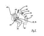
- the mounting hole 18 is particularly good FIG. 7 recognizable. It comprises a rigid frame 28 , which is closed by a cover 29 substantially gas-tight, wherein in FIG. 7 the cover 29 is shown only partially by way of example.
- the membrane unit 5 is sealingly connected to the frame 28 , so that at a transition from the plate unit 6 ' to the membrane unit 5 no gas from the interior 7 of the fermenter 2 can escape.
- the bearing device 15 After lowering the agitator 1 ' through the mounting opening 18 in the fermenter 2 , the bearing device 15, starting from a first vertical mounting position (the entire agitator depends on a lifting device) by means of the located on the bearing means 15 roller bearing 16 which includes the roller 17 , moved into its installed position.
- This process step is identical to the installation of the agitator 1 described above.
- the upper end of the agitator 1 ' is laterally moved out of the mounting opening 18 in a wall frame 30 , in which it is finally secured.
- the wall frame 30 forms a bearing opening 31 , in which the agitator 1 'can be fastened so that bearing forces are removed and can be absorbed by the wall 4 of the fermenter 2 .
- a transition from the mounting opening 18 in the bearing opening 31 is during assembly of the agitator 1 'free.
- the agitator 1' is in its operating position.
- the attachment is made by means of fixing plates 32, equally with the frame wall 30 and with a bearing plate 33 of the agitator 1 'are connected, wherein the bearing plate 33 directly below the driving means 13 of the agitator 1' is arranged.
- both the mounting opening 18 and the bearing opening 31 are closed in a substantially gas-tight manner.
- a transition between the mounting opening 18 and the bearing opening 31 is closed by means of a plank 34 which is screwed onto opposite sides of the wall 4 . This is especially good FIG. 7 ,
- the type of attachment of the agitator 1 ' in the wall 4 has the advantage that the ceiling device during operation of the fermenter 2 is free of agitators.
- the space required for the mounting opening 18 is comparatively small, so that a larger part of the ceiling device is formed by the membrane unit 5 .
- the fermenter 2 here has a height of about 10 m.
Landscapes
- Health & Medical Sciences (AREA)
- Life Sciences & Earth Sciences (AREA)
- Chemical & Material Sciences (AREA)
- Engineering & Computer Science (AREA)
- Wood Science & Technology (AREA)
- Organic Chemistry (AREA)
- Bioinformatics & Cheminformatics (AREA)
- Zoology (AREA)
- Genetics & Genomics (AREA)
- Biochemistry (AREA)
- Sustainable Development (AREA)
- Microbiology (AREA)
- Biotechnology (AREA)
- General Engineering & Computer Science (AREA)
- General Health & Medical Sciences (AREA)
- Biomedical Technology (AREA)
- Clinical Laboratory Science (AREA)
- Molecular Biology (AREA)
- General Chemical & Material Sciences (AREA)
- Oil, Petroleum & Natural Gas (AREA)
- Chemical Kinetics & Catalysis (AREA)
- Apparatus Associated With Microorganisms And Enzymes (AREA)
- Mixers Of The Rotary Stirring Type (AREA)
- Processing Of Solid Wastes (AREA)
- Mixers With Rotating Receptacles And Mixers With Vibration Mechanisms (AREA)
- Processing And Handling Of Plastics And Other Materials For Molding In General (AREA)
- Accessories For Mixers (AREA)
Priority Applications (2)
| Application Number | Priority Date | Filing Date | Title |
|---|---|---|---|
| PL14186392T PL2857493T3 (pl) | 2013-10-01 | 2014-09-25 | Mieszadło zbiornika, zbiornik oraz sposób montażu mieszadła w zbiorniku |
| HRP20191350 HRP20191350T1 (hr) | 2013-10-01 | 2019-07-26 | Miješalica za kontejner, kontejner i metoda za integraciju miješalice u kontejner |
Applications Claiming Priority (1)
| Application Number | Priority Date | Filing Date | Title |
|---|---|---|---|
| DE102013219938.4A DE102013219938A1 (de) | 2013-10-01 | 2013-10-01 | Rührwerk für einen Fermenter, Fermenter sowie Verfahren für den Einbau eines Rührwerks in einen Fermenter |
Publications (2)
| Publication Number | Publication Date |
|---|---|
| EP2857493A1 true EP2857493A1 (fr) | 2015-04-08 |
| EP2857493B1 EP2857493B1 (fr) | 2019-05-01 |
Family
ID=51619019
Family Applications (1)
| Application Number | Title | Priority Date | Filing Date |
|---|---|---|---|
| EP14186392.8A Active EP2857493B1 (fr) | 2013-10-01 | 2014-09-25 | Agitateur pour un récipient, récipient et procédé de montage d'un agitateur dans un récipient |
Country Status (10)
| Country | Link |
|---|---|
| US (1) | US9808776B2 (fr) |
| EP (1) | EP2857493B1 (fr) |
| BR (1) | BR102014024233B1 (fr) |
| CA (1) | CA2865361C (fr) |
| DE (1) | DE102013219938A1 (fr) |
| DK (1) | DK2857493T3 (fr) |
| ES (1) | ES2739077T3 (fr) |
| HR (1) | HRP20191350T1 (fr) |
| PL (1) | PL2857493T3 (fr) |
| TR (1) | TR201911207T4 (fr) |
Families Citing this family (5)
| Publication number | Priority date | Publication date | Assignee | Title |
|---|---|---|---|---|
| DE102017109271A1 (de) * | 2017-04-28 | 2018-10-31 | Patent Plus Bv | Anlage zur Behandlung fermentierbarer Substanzen |
| JP7019901B2 (ja) * | 2017-10-05 | 2022-02-16 | 前澤工業株式会社 | メタン発酵槽 |
| US11697789B2 (en) * | 2017-11-23 | 2023-07-11 | Mika Rautiainen | Reactor for manufacturing biogas from organic raw material using anaerobic digestion |
| DE102018133226A1 (de) | 2018-12-20 | 2020-06-25 | Jean-Marc Peters | Behälter sowie Verfahren zum Einbau eines Rührwerks in einen Behälter |
| CN114130235B (zh) * | 2021-11-04 | 2023-08-22 | 创合新材料科技江苏有限公司 | 一种pp专用增韧材料混料装置 |
Citations (13)
| Publication number | Priority date | Publication date | Assignee | Title |
|---|---|---|---|---|
| DE8312809U1 (de) | 1983-10-20 | Schaffer & Moser AG, Nottwil | Rührvorrichtung | |
| DE202004004101U1 (de) | 2004-03-16 | 2004-07-29 | U.T.S. Umwelt-Technik-Süd GmbH | Fermenter einer Biogasanlage mit einer Rühreinrichtung |
| DE102004027077A1 (de) | 2004-06-02 | 2006-01-05 | Schmack Biogas Ag | Beheizbares Rührwerk für Fermentationsbehälter |
| WO2007110775A2 (fr) | 2006-03-24 | 2007-10-04 | Luc Van Hyfte | Fixation articulee d'agitateur a palettes |
| DE202006011144U1 (de) | 2006-07-13 | 2007-11-29 | Envicon Klärtechnik GmbH & Co. KG | Hohlwelle für ein Rührwerk |
| DE102007034463A1 (de) | 2007-07-20 | 2009-01-29 | Sanofi-Aventis Deutschland Gmbh | Gleitlager und Reaktor hiermit |
| EP2064308A2 (fr) | 2005-09-02 | 2009-06-03 | Agraferm Technologies AG | Melangeur-agitateur pour fermenteur, fermenteur et procede pour actionner un fermenteur |
| DE202009010167U1 (de) | 2009-07-27 | 2009-10-01 | R.E.U.S. Energy Gmbh | Hub- und Schwenkvorrichtung für ein höhenverstellbares angetriebenes Tauchgerät an einem Fermenterbehälter einer Biogasanlage |
| DE102009041569A1 (de) * | 2009-09-15 | 2011-04-07 | Sbbiogas Gmbh | Anlage zur Erzeugung von Biogas |
| DE102010053242A1 (de) * | 2009-12-16 | 2011-06-22 | NQ-Anlagentechnik GmbH, 86733 | Faulbehälter zur Erzeugung von Biogas |
| WO2011139209A1 (fr) | 2010-05-06 | 2011-11-10 | Itt Manufacturing Enterprises Inc | Ensemble mélangeur pour cuve de digestion |
| DE202013006429U1 (de) * | 2013-07-17 | 2013-08-08 | BHKW Johann Hochreiter Biogas Planung Beratung GmbH | Vorrichtung zum Durchmischen des Inhalts von Substratbehältern |
| EP2636444A1 (fr) | 2012-03-08 | 2013-09-11 | Michael Niederbacher | Récipient de fermentation pour installation de biogaz doté d'un dispositif de service et dispositif de service |
Family Cites Families (7)
| Publication number | Priority date | Publication date | Assignee | Title |
|---|---|---|---|---|
| US859943A (en) * | 1906-10-03 | 1907-07-16 | Elbridge G Holden | Mixer for liquids or semiliquids. |
| US2154535A (en) * | 1936-09-16 | 1939-04-18 | Libbey Glass Co | Glass circulating apparatus |
| US2625720A (en) * | 1949-12-16 | 1953-01-20 | Internat Newspaper Supply Corp | Pump for type casting |
| US2559196A (en) * | 1950-07-12 | 1951-07-03 | Nicholas J Medved | Time saver frying pan lid |
| JP3283770B2 (ja) * | 1996-11-05 | 2002-05-20 | 富士車輌株式会社 | 攪拌装置 |
| DE10027343A1 (de) * | 2000-06-02 | 2001-12-20 | Bayer Ag | Fußlager für Rührwellen |
| DE102009056967B4 (de) * | 2009-12-07 | 2013-07-04 | Sartorius Stedim Biotech Gmbh | Mischvorrichtung |
-
2013
- 2013-10-01 DE DE102013219938.4A patent/DE102013219938A1/de not_active Withdrawn
-
2014
- 2014-09-25 DK DK14186392.8T patent/DK2857493T3/da active
- 2014-09-25 TR TR2019/11207T patent/TR201911207T4/tr unknown
- 2014-09-25 ES ES14186392T patent/ES2739077T3/es active Active
- 2014-09-25 PL PL14186392T patent/PL2857493T3/pl unknown
- 2014-09-25 EP EP14186392.8A patent/EP2857493B1/fr active Active
- 2014-09-26 US US14/497,406 patent/US9808776B2/en active Active
- 2014-09-29 BR BR102014024233-3A patent/BR102014024233B1/pt active IP Right Grant
- 2014-09-30 CA CA2865361A patent/CA2865361C/fr active Active
-
2019
- 2019-07-26 HR HRP20191350 patent/HRP20191350T1/hr unknown
Patent Citations (13)
| Publication number | Priority date | Publication date | Assignee | Title |
|---|---|---|---|---|
| DE8312809U1 (de) | 1983-10-20 | Schaffer & Moser AG, Nottwil | Rührvorrichtung | |
| DE202004004101U1 (de) | 2004-03-16 | 2004-07-29 | U.T.S. Umwelt-Technik-Süd GmbH | Fermenter einer Biogasanlage mit einer Rühreinrichtung |
| DE102004027077A1 (de) | 2004-06-02 | 2006-01-05 | Schmack Biogas Ag | Beheizbares Rührwerk für Fermentationsbehälter |
| EP2064308A2 (fr) | 2005-09-02 | 2009-06-03 | Agraferm Technologies AG | Melangeur-agitateur pour fermenteur, fermenteur et procede pour actionner un fermenteur |
| WO2007110775A2 (fr) | 2006-03-24 | 2007-10-04 | Luc Van Hyfte | Fixation articulee d'agitateur a palettes |
| DE202006011144U1 (de) | 2006-07-13 | 2007-11-29 | Envicon Klärtechnik GmbH & Co. KG | Hohlwelle für ein Rührwerk |
| DE102007034463A1 (de) | 2007-07-20 | 2009-01-29 | Sanofi-Aventis Deutschland Gmbh | Gleitlager und Reaktor hiermit |
| DE202009010167U1 (de) | 2009-07-27 | 2009-10-01 | R.E.U.S. Energy Gmbh | Hub- und Schwenkvorrichtung für ein höhenverstellbares angetriebenes Tauchgerät an einem Fermenterbehälter einer Biogasanlage |
| DE102009041569A1 (de) * | 2009-09-15 | 2011-04-07 | Sbbiogas Gmbh | Anlage zur Erzeugung von Biogas |
| DE102010053242A1 (de) * | 2009-12-16 | 2011-06-22 | NQ-Anlagentechnik GmbH, 86733 | Faulbehälter zur Erzeugung von Biogas |
| WO2011139209A1 (fr) | 2010-05-06 | 2011-11-10 | Itt Manufacturing Enterprises Inc | Ensemble mélangeur pour cuve de digestion |
| EP2636444A1 (fr) | 2012-03-08 | 2013-09-11 | Michael Niederbacher | Récipient de fermentation pour installation de biogaz doté d'un dispositif de service et dispositif de service |
| DE202013006429U1 (de) * | 2013-07-17 | 2013-08-08 | BHKW Johann Hochreiter Biogas Planung Beratung GmbH | Vorrichtung zum Durchmischen des Inhalts von Substratbehältern |
Also Published As
| Publication number | Publication date |
|---|---|
| DK2857493T3 (da) | 2019-08-05 |
| TR201911207T4 (tr) | 2019-08-21 |
| BR102014024233A2 (pt) | 2016-07-12 |
| ES2739077T3 (es) | 2020-01-28 |
| US20150093811A1 (en) | 2015-04-02 |
| CA2865361A1 (fr) | 2015-04-01 |
| PL2857493T3 (pl) | 2019-12-31 |
| CA2865361C (fr) | 2018-04-03 |
| HRP20191350T1 (hr) | 2019-11-01 |
| BR102014024233B1 (pt) | 2021-06-29 |
| DE102013219938A1 (de) | 2015-04-02 |
| US9808776B2 (en) | 2017-11-07 |
| EP2857493B1 (fr) | 2019-05-01 |
Similar Documents
| Publication | Publication Date | Title |
|---|---|---|
| EP2857493B1 (fr) | Agitateur pour un récipient, récipient et procédé de montage d'un agitateur dans un récipient | |
| EP2304018B1 (fr) | Fermenteur du type bassin enterré | |
| EP2389432B1 (fr) | Système de service pour installation de production de biogaz | |
| EP0894525B1 (fr) | Dispositif de soulèvement pour un aggregat, en particulier un agitateur submersible motorisé dans une cuve hermétique | |
| DE202004004101U1 (de) | Fermenter einer Biogasanlage mit einer Rühreinrichtung | |
| EP2677095B1 (fr) | Monte-personnes pour parois en surplomb ou à courbure convexe | |
| DE102008022654A1 (de) | Verfahren und Vorrichtung zur Montage eines modulartigen Bauwerks, wie einer Windenergieanlage | |
| EP2270128B1 (fr) | Installation de biogaz et élement de regard pour une installation de biogaz | |
| WO2014015948A2 (fr) | Installation à biogaz | |
| EP3898930A1 (fr) | Récipient ainsi que procédé pour le montage d'un malaxeur dans un récipient | |
| EP2500085A1 (fr) | Dispositif de réglage en hauteur pour centrale de malaxage ou de pompage immergée | |
| DE102015114992A1 (de) | Rollenpresse | |
| WO2013131627A1 (fr) | Récipient de fermentation d'installations de biogaz doté d'un dispositif d'entretien ainsi que dispositif d'entretien | |
| DE102011118204A1 (de) | Mischeinrichtung für Behälter auf Biogasanlagen und dergleichen | |
| EP2455151B1 (fr) | Dispositif de traction de câble, notamment système de palan pour une scène ou analogue | |
| DE102024113850A1 (de) | Arbeitsvorrichtung und Verwendungsverfahren | |
| DE102014011878B4 (de) | Bodenfräsmaschine, Verfahren zum Ausbau und Verfahren zum Einbau einer Fräseinrichtung | |
| EP1130084A1 (fr) | Installation de biogaz pour la fermentation de matériaux organiques | |
| DE102010000489B4 (de) | Vorrichtung | |
| EP2826353B1 (fr) | Couverture pour réservoir | |
| DE102009045492B4 (de) | Lagervorrichtung für ein drehbares Gebäude | |
| DE102012021206A1 (de) | Fermenter einer Biogasanlage | |
| EP2730738A1 (fr) | Dispositif à enroulement destiné à recouvrir des ouvertures dans des sections de mur | |
| EP3556458B1 (fr) | Agitateur immergé | |
| EP1972731A2 (fr) | Dispositif de rotation pour un bâtiment |
Legal Events
| Date | Code | Title | Description |
|---|---|---|---|
| PUAI | Public reference made under article 153(3) epc to a published international application that has entered the european phase |
Free format text: ORIGINAL CODE: 0009012 |
|
| 17P | Request for examination filed |
Effective date: 20140925 |
|
| AK | Designated contracting states |
Kind code of ref document: A1 Designated state(s): AL AT BE BG CH CY CZ DE DK EE ES FI FR GB GR HR HU IE IS IT LI LT LU LV MC MK MT NL NO PL PT RO RS SE SI SK SM TR |
|
| AX | Request for extension of the european patent |
Extension state: BA ME |
|
| R17P | Request for examination filed (corrected) |
Effective date: 20151007 |
|
| RBV | Designated contracting states (corrected) |
Designated state(s): AL AT BE BG CH CY CZ DE DK EE ES FI FR GB GR HR HU IE IS IT LI LT LU LV MC MK MT NL NO PL PT RO RS SE SI SK SM TR |
|
| STAA | Information on the status of an ep patent application or granted ep patent |
Free format text: STATUS: EXAMINATION IS IN PROGRESS |
|
| 17Q | First examination report despatched |
Effective date: 20180523 |
|
| GRAP | Despatch of communication of intention to grant a patent |
Free format text: ORIGINAL CODE: EPIDOSNIGR1 |
|
| STAA | Information on the status of an ep patent application or granted ep patent |
Free format text: STATUS: GRANT OF PATENT IS INTENDED |
|
| INTG | Intention to grant announced |
Effective date: 20180926 |
|
| GRAS | Grant fee paid |
Free format text: ORIGINAL CODE: EPIDOSNIGR3 |
|
| GRAA | (expected) grant |
Free format text: ORIGINAL CODE: 0009210 |
|
| STAA | Information on the status of an ep patent application or granted ep patent |
Free format text: STATUS: THE PATENT HAS BEEN GRANTED |
|
| AK | Designated contracting states |
Kind code of ref document: B1 Designated state(s): AL AT BE BG CH CY CZ DE DK EE ES FI FR GB GR HR HU IE IS IT LI LT LU LV MC MK MT NL NO PL PT RO RS SE SI SK SM TR |
|
| REG | Reference to a national code |
Ref country code: GB Ref legal event code: FG4D Free format text: NOT ENGLISH |
|
| REG | Reference to a national code |
Ref country code: CH Ref legal event code: EP Ref country code: AT Ref legal event code: REF Ref document number: 1126885 Country of ref document: AT Kind code of ref document: T Effective date: 20190515 |
|
| REG | Reference to a national code |
Ref country code: DE Ref legal event code: R096 Ref document number: 502014011565 Country of ref document: DE |
|
| REG | Reference to a national code |
Ref country code: IE Ref legal event code: FG4D Free format text: LANGUAGE OF EP DOCUMENT: GERMAN |
|
| REG | Reference to a national code |
Ref country code: HR Ref legal event code: TUEP Ref document number: P20191350 Country of ref document: HR |
|
| REG | Reference to a national code |
Ref country code: DK Ref legal event code: T3 Effective date: 20190731 |
|
| REG | Reference to a national code |
Ref country code: NL Ref legal event code: FP |
|
| REG | Reference to a national code |
Ref country code: SE Ref legal event code: TRGR |
|
| REG | Reference to a national code |
Ref country code: CH Ref legal event code: NV Representative=s name: VALIPAT S.A. C/O BOVARD SA NEUCHATEL, CH |
|
| REG | Reference to a national code |
Ref country code: LT Ref legal event code: MG4D |
|
| REG | Reference to a national code |
Ref country code: NO Ref legal event code: T2 Effective date: 20190501 |
|
| PG25 | Lapsed in a contracting state [announced via postgrant information from national office to epo] |
Ref country code: FI Free format text: LAPSE BECAUSE OF FAILURE TO SUBMIT A TRANSLATION OF THE DESCRIPTION OR TO PAY THE FEE WITHIN THE PRESCRIBED TIME-LIMIT Effective date: 20190501 Ref country code: AL Free format text: LAPSE BECAUSE OF FAILURE TO SUBMIT A TRANSLATION OF THE DESCRIPTION OR TO PAY THE FEE WITHIN THE PRESCRIBED TIME-LIMIT Effective date: 20190501 Ref country code: PT Free format text: LAPSE BECAUSE OF FAILURE TO SUBMIT A TRANSLATION OF THE DESCRIPTION OR TO PAY THE FEE WITHIN THE PRESCRIBED TIME-LIMIT Effective date: 20190901 Ref country code: LT Free format text: LAPSE BECAUSE OF FAILURE TO SUBMIT A TRANSLATION OF THE DESCRIPTION OR TO PAY THE FEE WITHIN THE PRESCRIBED TIME-LIMIT Effective date: 20190501 |
|
| REG | Reference to a national code |
Ref country code: HR Ref legal event code: T1PR Ref document number: P20191350 Country of ref document: HR |
|
| REG | Reference to a national code |
Ref country code: SK Ref legal event code: T3 Ref document number: E 31774 Country of ref document: SK |
|
| PG25 | Lapsed in a contracting state [announced via postgrant information from national office to epo] |
Ref country code: RS Free format text: LAPSE BECAUSE OF FAILURE TO SUBMIT A TRANSLATION OF THE DESCRIPTION OR TO PAY THE FEE WITHIN THE PRESCRIBED TIME-LIMIT Effective date: 20190501 Ref country code: BG Free format text: LAPSE BECAUSE OF FAILURE TO SUBMIT A TRANSLATION OF THE DESCRIPTION OR TO PAY THE FEE WITHIN THE PRESCRIBED TIME-LIMIT Effective date: 20190801 |
|
| PG25 | Lapsed in a contracting state [announced via postgrant information from national office to epo] |
Ref country code: IS Free format text: LAPSE BECAUSE OF FAILURE TO SUBMIT A TRANSLATION OF THE DESCRIPTION OR TO PAY THE FEE WITHIN THE PRESCRIBED TIME-LIMIT Effective date: 20190901 |
|
| REG | Reference to a national code |
Ref country code: GR Ref legal event code: EP Ref document number: 20190402293 Country of ref document: GR Effective date: 20191128 |
|
| REG | Reference to a national code |
Ref country code: ES Ref legal event code: FG2A Ref document number: 2739077 Country of ref document: ES Kind code of ref document: T3 Effective date: 20200128 |
|
| PG25 | Lapsed in a contracting state [announced via postgrant information from national office to epo] |
Ref country code: RO Free format text: LAPSE BECAUSE OF FAILURE TO SUBMIT A TRANSLATION OF THE DESCRIPTION OR TO PAY THE FEE WITHIN THE PRESCRIBED TIME-LIMIT Effective date: 20190501 Ref country code: EE Free format text: LAPSE BECAUSE OF FAILURE TO SUBMIT A TRANSLATION OF THE DESCRIPTION OR TO PAY THE FEE WITHIN THE PRESCRIBED TIME-LIMIT Effective date: 20190501 |
|
| REG | Reference to a national code |
Ref country code: DE Ref legal event code: R097 Ref document number: 502014011565 Country of ref document: DE |
|
| PG25 | Lapsed in a contracting state [announced via postgrant information from national office to epo] |
Ref country code: SM Free format text: LAPSE BECAUSE OF FAILURE TO SUBMIT A TRANSLATION OF THE DESCRIPTION OR TO PAY THE FEE WITHIN THE PRESCRIBED TIME-LIMIT Effective date: 20190501 |
|
| PLBE | No opposition filed within time limit |
Free format text: ORIGINAL CODE: 0009261 |
|
| STAA | Information on the status of an ep patent application or granted ep patent |
Free format text: STATUS: NO OPPOSITION FILED WITHIN TIME LIMIT |
|
| REG | Reference to a national code |
Ref country code: HR Ref legal event code: PBON Ref document number: P20191350 Country of ref document: HR Effective date: 20190925 |
|
| 26N | No opposition filed |
Effective date: 20200204 |
|
| PG25 | Lapsed in a contracting state [announced via postgrant information from national office to epo] |
Ref country code: LV Free format text: LAPSE BECAUSE OF NON-PAYMENT OF DUE FEES Effective date: 20190925 |
|
| PG25 | Lapsed in a contracting state [announced via postgrant information from national office to epo] |
Ref country code: SI Free format text: LAPSE BECAUSE OF FAILURE TO SUBMIT A TRANSLATION OF THE DESCRIPTION OR TO PAY THE FEE WITHIN THE PRESCRIBED TIME-LIMIT Effective date: 20190501 Ref country code: MC Free format text: LAPSE BECAUSE OF FAILURE TO SUBMIT A TRANSLATION OF THE DESCRIPTION OR TO PAY THE FEE WITHIN THE PRESCRIBED TIME-LIMIT Effective date: 20190501 |
|
| PG25 | Lapsed in a contracting state [announced via postgrant information from national office to epo] |
Ref country code: GR Free format text: LAPSE BECAUSE OF NON-PAYMENT OF DUE FEES Effective date: 20200416 |
|
| PG25 | Lapsed in a contracting state [announced via postgrant information from national office to epo] |
Ref country code: HR Free format text: LAPSE BECAUSE OF NON-PAYMENT OF DUE FEES Effective date: 20190925 |
|
| PGFP | Annual fee paid to national office [announced via postgrant information from national office to epo] |
Ref country code: DK Payment date: 20200925 Year of fee payment: 7 Ref country code: CZ Payment date: 20200923 Year of fee payment: 7 Ref country code: IE Payment date: 20200918 Year of fee payment: 7 Ref country code: NO Payment date: 20200922 Year of fee payment: 7 Ref country code: LU Payment date: 20200925 Year of fee payment: 7 Ref country code: SK Payment date: 20200907 Year of fee payment: 7 |
|
| PGFP | Annual fee paid to national office [announced via postgrant information from national office to epo] |
Ref country code: PL Payment date: 20200901 Year of fee payment: 7 Ref country code: AT Payment date: 20200918 Year of fee payment: 7 Ref country code: SE Payment date: 20200925 Year of fee payment: 7 |
|
| PGFP | Annual fee paid to national office [announced via postgrant information from national office to epo] |
Ref country code: ES Payment date: 20201020 Year of fee payment: 7 |
|
| PG25 | Lapsed in a contracting state [announced via postgrant information from national office to epo] |
Ref country code: CY Free format text: LAPSE BECAUSE OF FAILURE TO SUBMIT A TRANSLATION OF THE DESCRIPTION OR TO PAY THE FEE WITHIN THE PRESCRIBED TIME-LIMIT Effective date: 20190501 |
|
| PG25 | Lapsed in a contracting state [announced via postgrant information from national office to epo] |
Ref country code: MT Free format text: LAPSE BECAUSE OF FAILURE TO SUBMIT A TRANSLATION OF THE DESCRIPTION OR TO PAY THE FEE WITHIN THE PRESCRIBED TIME-LIMIT Effective date: 20190501 Ref country code: HU Free format text: LAPSE BECAUSE OF FAILURE TO SUBMIT A TRANSLATION OF THE DESCRIPTION OR TO PAY THE FEE WITHIN THE PRESCRIBED TIME-LIMIT; INVALID AB INITIO Effective date: 20140925 |
|
| REG | Reference to a national code |
Ref country code: DE Ref legal event code: R082 Ref document number: 502014011565 Country of ref document: DE Representative=s name: BAUER WAGNER PELLENGAHR SROKA PATENT- & RECHTS, DE Ref country code: DE Ref legal event code: R082 Ref document number: 502014011565 Country of ref document: DE Representative=s name: BAUER PSU PARTG MBB, DE |
|
| REG | Reference to a national code |
Ref country code: NO Ref legal event code: MMEP |
|
| REG | Reference to a national code |
Ref country code: DK Ref legal event code: EBP Effective date: 20210930 |
|
| REG | Reference to a national code |
Ref country code: SE Ref legal event code: EUG |
|
| REG | Reference to a national code |
Ref country code: SK Ref legal event code: MM4A Ref document number: E 31774 Country of ref document: SK Effective date: 20210925 |
|
| REG | Reference to a national code |
Ref country code: AT Ref legal event code: MM01 Ref document number: 1126885 Country of ref document: AT Kind code of ref document: T Effective date: 20210925 |
|
| PG25 | Lapsed in a contracting state [announced via postgrant information from national office to epo] |
Ref country code: CZ Free format text: LAPSE BECAUSE OF NON-PAYMENT OF DUE FEES Effective date: 20210925 |
|
| PG25 | Lapsed in a contracting state [announced via postgrant information from national office to epo] |
Ref country code: MK Free format text: LAPSE BECAUSE OF FAILURE TO SUBMIT A TRANSLATION OF THE DESCRIPTION OR TO PAY THE FEE WITHIN THE PRESCRIBED TIME-LIMIT Effective date: 20190501 |
|
| PG25 | Lapsed in a contracting state [announced via postgrant information from national office to epo] |
Ref country code: SK Free format text: LAPSE BECAUSE OF NON-PAYMENT OF DUE FEES Effective date: 20210925 Ref country code: SE Free format text: LAPSE BECAUSE OF NON-PAYMENT OF DUE FEES Effective date: 20210926 Ref country code: NO Free format text: LAPSE BECAUSE OF NON-PAYMENT OF DUE FEES Effective date: 20210930 Ref country code: LU Free format text: LAPSE BECAUSE OF NON-PAYMENT OF DUE FEES Effective date: 20210925 Ref country code: IE Free format text: LAPSE BECAUSE OF NON-PAYMENT OF DUE FEES Effective date: 20210925 |
|
| PG25 | Lapsed in a contracting state [announced via postgrant information from national office to epo] |
Ref country code: AT Free format text: LAPSE BECAUSE OF NON-PAYMENT OF DUE FEES Effective date: 20210925 |
|
| PG25 | Lapsed in a contracting state [announced via postgrant information from national office to epo] |
Ref country code: DK Free format text: LAPSE BECAUSE OF NON-PAYMENT OF DUE FEES Effective date: 20210930 |
|
| REG | Reference to a national code |
Ref country code: ES Ref legal event code: FD2A Effective date: 20221107 |
|
| PG25 | Lapsed in a contracting state [announced via postgrant information from national office to epo] |
Ref country code: ES Free format text: LAPSE BECAUSE OF NON-PAYMENT OF DUE FEES Effective date: 20210926 |
|
| PG25 | Lapsed in a contracting state [announced via postgrant information from national office to epo] |
Ref country code: PL Free format text: LAPSE BECAUSE OF NON-PAYMENT OF DUE FEES Effective date: 20210925 |
|
| P01 | Opt-out of the competence of the unified patent court (upc) registered |
Effective date: 20230522 |
|
| REG | Reference to a national code |
Ref country code: CH Ref legal event code: U11 Free format text: ST27 STATUS EVENT CODE: U-0-0-U10-U11 (AS PROVIDED BY THE NATIONAL OFFICE) Effective date: 20251001 |
|
| PGFP | Annual fee paid to national office [announced via postgrant information from national office to epo] |
Ref country code: DE Payment date: 20250930 Year of fee payment: 12 |
|
| PGFP | Annual fee paid to national office [announced via postgrant information from national office to epo] |
Ref country code: TR Payment date: 20250905 Year of fee payment: 12 Ref country code: NL Payment date: 20250925 Year of fee payment: 12 Ref country code: IT Payment date: 20250922 Year of fee payment: 12 |
|
| PGFP | Annual fee paid to national office [announced via postgrant information from national office to epo] |
Ref country code: GB Payment date: 20250923 Year of fee payment: 12 Ref country code: BE Payment date: 20250925 Year of fee payment: 12 |
|
| PGFP | Annual fee paid to national office [announced via postgrant information from national office to epo] |
Ref country code: FR Payment date: 20250925 Year of fee payment: 12 |
|
| PGFP | Annual fee paid to national office [announced via postgrant information from national office to epo] |
Ref country code: CH Payment date: 20251001 Year of fee payment: 12 |