EP2858754B1 - Broyeur ayant une évacuation latérale - Google Patents
Broyeur ayant une évacuation latérale Download PDFInfo
- Publication number
- EP2858754B1 EP2858754B1 EP13804621.4A EP13804621A EP2858754B1 EP 2858754 B1 EP2858754 B1 EP 2858754B1 EP 13804621 A EP13804621 A EP 13804621A EP 2858754 B1 EP2858754 B1 EP 2858754B1
- Authority
- EP
- European Patent Office
- Prior art keywords
- drum
- cutting
- cutting drum
- machine
- channel
- Prior art date
- Legal status (The legal status is an assumption and is not a legal conclusion. Google has not performed a legal analysis and makes no representation as to the accuracy of the status listed.)
- Active
Links
Images


Classifications
-
- B—PERFORMING OPERATIONS; TRANSPORTING
- B02—CRUSHING, PULVERISING, OR DISINTEGRATING; PREPARATORY TREATMENT OF GRAIN FOR MILLING
- B02C—CRUSHING, PULVERISING, OR DISINTEGRATING IN GENERAL; MILLING GRAIN
- B02C18/00—Disintegrating by knives or other cutting or tearing members which chop material into fragments
- B02C18/06—Disintegrating by knives or other cutting or tearing members which chop material into fragments with rotating knives
- B02C18/16—Details
- B02C18/22—Feed or discharge means
- B02C18/2216—Discharge means
-
- A—HUMAN NECESSITIES
- A01—AGRICULTURE; FORESTRY; ANIMAL HUSBANDRY; HUNTING; TRAPPING; FISHING
- A01G—HORTICULTURE; CULTIVATION OF VEGETABLES, FLOWERS, RICE, FRUIT, VINES, HOPS OR SEAWEED; FORESTRY; WATERING
- A01G3/00—Cutting implements specially adapted for horticultural purposes; Delimbing standing trees
- A01G3/002—Cutting implements specially adapted for horticultural purposes; Delimbing standing trees for comminuting plant waste
-
- B—PERFORMING OPERATIONS; TRANSPORTING
- B02—CRUSHING, PULVERISING, OR DISINTEGRATING; PREPARATORY TREATMENT OF GRAIN FOR MILLING
- B02C—CRUSHING, PULVERISING, OR DISINTEGRATING IN GENERAL; MILLING GRAIN
- B02C18/00—Disintegrating by knives or other cutting or tearing members which chop material into fragments
- B02C18/06—Disintegrating by knives or other cutting or tearing members which chop material into fragments with rotating knives
- B02C18/14—Disintegrating by knives or other cutting or tearing members which chop material into fragments with rotating knives within horizontal containers
- B02C18/144—Disintegrating by knives or other cutting or tearing members which chop material into fragments with rotating knives within horizontal containers with axially elongated knives
-
- B—PERFORMING OPERATIONS; TRANSPORTING
- B02—CRUSHING, PULVERISING, OR DISINTEGRATING; PREPARATORY TREATMENT OF GRAIN FOR MILLING
- B02C—CRUSHING, PULVERISING, OR DISINTEGRATING IN GENERAL; MILLING GRAIN
- B02C18/00—Disintegrating by knives or other cutting or tearing members which chop material into fragments
- B02C18/06—Disintegrating by knives or other cutting or tearing members which chop material into fragments with rotating knives
- B02C18/14—Disintegrating by knives or other cutting or tearing members which chop material into fragments with rotating knives within horizontal containers
- B02C18/145—Disintegrating by knives or other cutting or tearing members which chop material into fragments with rotating knives within horizontal containers with knives spaced axially and circumferentially on the periphery of a cylindrical rotor unit
-
- B—PERFORMING OPERATIONS; TRANSPORTING
- B02—CRUSHING, PULVERISING, OR DISINTEGRATING; PREPARATORY TREATMENT OF GRAIN FOR MILLING
- B02C—CRUSHING, PULVERISING, OR DISINTEGRATING IN GENERAL; MILLING GRAIN
- B02C18/00—Disintegrating by knives or other cutting or tearing members which chop material into fragments
- B02C18/06—Disintegrating by knives or other cutting or tearing members which chop material into fragments with rotating knives
- B02C18/16—Details
- B02C2018/162—Shape or inner surface of shredder-housings
-
- B—PERFORMING OPERATIONS; TRANSPORTING
- B02—CRUSHING, PULVERISING, OR DISINTEGRATING; PREPARATORY TREATMENT OF GRAIN FOR MILLING
- B02C—CRUSHING, PULVERISING, OR DISINTEGRATING IN GENERAL; MILLING GRAIN
- B02C21/00—Disintegrating plant with or without drying of the material
- B02C21/02—Transportable disintegrating plant
-
- B—PERFORMING OPERATIONS; TRANSPORTING
- B02—CRUSHING, PULVERISING, OR DISINTEGRATING; PREPARATORY TREATMENT OF GRAIN FOR MILLING
- B02C—CRUSHING, PULVERISING, OR DISINTEGRATING IN GENERAL; MILLING GRAIN
- B02C2201/00—Codes relating to disintegrating devices adapted for specific materials
- B02C2201/06—Codes relating to disintegrating devices adapted for specific materials for garbage, waste or sewage
- B02C2201/066—Codes relating to disintegrating devices adapted for specific materials for garbage, waste or sewage for garden waste
Definitions
- the present invention relates to, and is entitled to the benefit of the earlier filing date and priority of: U.S. Provisional Patent Application No. 61/658431 filed June 12, 2012 , entitled, "SHREDDER WITH A SIDE DISCHARGE, naming the same inventor as named herein, Thomas R. Gross.
- the present invention relates to machines for reducing materials, including materials made of wood or other fibrous materials, and more particularly to drum chippers.
- Drum chippers and shredders for reducing wood are generally known, see for example U.S. Patent No. 8,118,245 entitled Self-contained Shredder Assembly for Reducing and Sizing Material; No. 7,909,275 entitled Self-contained Shredder Assembly for Reducing and Sizing Material; No. 7,552,884 entitled Drum Shredder with Flywheel or Discharge Assembly; No. 7,513,449 entitled Wood Collection and Reducing Machine; and No. 6,824,089 entitled Wood Collection and Reducing Machine.
- US-5692548-A discloses a machine according to the preamble of claim 1. However, what is needed is a new machine design for reducing material that can utilize a more conventional style cutting drum and has excellent material discharge efficiency.
- the present invention is a machine for reducing material according to claim 1. Preferred embodiments are defined by the dependent claims.
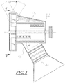
- FIG. 1-4 are perspective views in part showing embodiments of machines for reducing material having a cylindrical cutting drum and a side discharge assembly.
- the shredder includes a cutting drum.
- the cutting drum is cylindrical.
- a cylindrical cutting drum is one that has a cross-section with an outer diameter that is essentially uniform along its length. As shown, the cutting drum has an essentially circular cross-section that is essentially uniform along its length.
- the cutting drum is preferably adapted to radially carry chips on the outside of the drum, and as such, may be essentially imperforate, impervious or impenetrable to reduced material so that chips may not pass radially inwardly through the outer wall or skin of the drum.
- a cutting drum adapted to radially carry chips on the outside of the drum may be adapted for carrying chips radially in any suitable manner, such as having a drum with a solid surface or imperforate skin, with small holes which are impenetrable by the reduced material, with a continuous outer surface that includes extended blades with a channel disposed beneath the blades, and/or by providing at least one channel in the surface of the drum for carrying chips.
- the cutting drum has a substantially uniform, smooth outer surface, other than the cutting implements, associated hardware, and channels.
- the cutting drum may be hollow, essentially solid, or solid. However, it is noted that any channels in the surface of the drum are essentially imperforate to reduced material so that the surface of the drum still precludes reduced material from passing radially inwardly into the drum.
- a hollow cutting drum allows for making a larger cutting head with reduced weight, which can reduce material costs and provide ease of handling.
- a hollow center may also be used for fixing a drive shaft therein.
- a solid or essentially solid cutting drum provides a heavy member with increased stability and may also provide increased momentum so that chipping large branches does not hamper the speed of the drum or the cutting blade(s) during operation.
- the cutting drum may be made of any suitable material, such as cast alloy, forged steel, cast iron, steel plate, other hard materials, etc.
- the drum has a skin or outer surface made of steel plate, the steel plate formed and welded on the inside to arrange the plates.
- the cutting drum may be angled in relation to the in-feed. By angling the cutting drum, the cutting drum blade, chip efficiency, and quality can be increased.
- the drum face may angle towards the discharge assembly.
- the cutting drum face may be angled in relation to the in-feed 20 degrees or more, and may angle between 20 and 40 degrees relative to the in-feed.
- wood or other material can be fed to a rotating drum where one or more cutting implements impact on the material at an angle to the grain, for example, as in the case of logs.
- the cutting drum preferably has at least one cutting implement.
- the cutting implement may be any suitable reducing device.
- the reducing device is preferably selected based on the particular material reduction operation being performed.
- Suitable cutting implements include: blades, spikes, fixed or swinging hammers, etc.
- the cutting implements are blades disposed about the outer surface of the drum.
- a cutting blade is an elongated knife(s) or chisel(s) that extend(s) longitudinally along some portion of the cutting axis of the cutting drum. Blades are particularly good cutting implements for reducing wood.
- Each blade may be connected to the cutting drum at an acute angle relative to the surface thereof to enhance chipping and material draw into the shredder.
- the cutting drum has a plurality of cutting implements wherein each cutting implement extends less than the entire length of the cutting drum. In a preferred embodiment each cutting implement extends 50% or less of the length of the cutting drum. Cutting implements that extend less than the length of the cutting drum may be used to reduce material draw and drum stalling. Cutting implements that extend less than the entire length of the cutting drum are preferably staggered over the surface of the drum. Staggered cutting implements can be used to control the feed rate of material into the blades during operation. Staggered cutting implements may be distributed about the surface of the drum to give at least one full cut per drum rotation. Staggered cutting implements may also be distributed over the surface of the cutting head to increase the amount of cuts along any one section of the drum.
- the cutting blade may be straight or curved with a straight or curve edge. Each cutting blade may have multiple edges so that the blade may be repositioned to provide a fresh, sharpened edge.
- the cutting implement may be removably attached to the drum.
- the cutting implement may be removably fixed to the drum with a blade keeper.
- the blade keeper is a block or bearing that may be tapped to receive one or more bolts or other fasteners to hold the blades to the drum.
- Each cutting blade may be formed by combining multiple, smaller blade sections together, such as by providing a number of smaller blades adjacent to one another. Multiple blade sections can provide a single edge with sections that can be replaced independently of other sections. The sections of the single edge may be of different lengths.
- the cutting drum preferably has at least one channel.
- Each channel may be associated with one or more cutting implements.
- Each channel may be disposed adjacent to one cutting implement so that the channel can receive reduced material from said cutting implement and may precede the cutting implement as measured by the direction of drum rotation.
- the channels are elongated, radially outwardly opening depressions or cups that have a set of walls and a floor which form a channel basin.
- the at least one channel may open at one end of the channel. In certain embodiments the at least one channel may open at the end of the drum. In other embodiments it was found that the at least one channel does not have to open at either end, and may be at least partially blocked (as shown).
- Each channel may present a concave radially outwardly facing cross sectional configuration so as to trap reduced material on the outer surface of the drum and preclude the passage of reduced material radially inwardly into the drum into the interior of the drum.
- Each channel preferably has a floor or basin that is imperforate to reduced material.
- each channel is disposed prior to the associated cutting implement (as measured in relation to the cutting blade and direction of drum rotation).
- the at least one channel extends the length of a cutting region, drum section or the entire cutting drum.
- the channel only extends the length of the associated cutting implement.
- the channel may be blocked by any suitable blocking device or block, such as a wall, butt plate, blank, etc. As shown the channels are blocked at both ends.
- the blocking device or block maybe a butt plate supported by the drum.
- the at least one channel may open at one end to at least temporarily communicate with a material accelerator chamber.
- the shredder may have at least one paddle and may have a plurality of paddles.
- the paddles may be joined with the cutting drum.
- the paddle(s) may be formed of any suitable material, such as an alloy, composite, plastic, etc.
- the shredder may have three or more paddles, four or more, five or more, or six or more paddles disposed at an end of the drum to aid in reduced material discharge.
- the paddle(s) may aid in reduced material discharge by providing airflow through the discharge assembly and may also act to directly move and throw material that comes into contact with the paddles.
- the paddles may be evenly spaced about the outer side(s) of the cutting drum, drive shaft. The paddles preferably act to generate air currents when the drum rotates.
- Preferred arrangements include paddles positioned at 12, 3, 6 and 9 o'clock of the drum. Extra paddles may also be added at 1 and 7 o'clock, etc. Extra paddles may be added in a manner that increases discharge efficiency while keeping rotational balance of the device they are mounted, such as the drum.
- the paddles are preferably formed, sized and angled for the type of material that the paddles are to move.
- the paddle(s) are preferably positioned in the material accelerator chamber.
- the paddles may be rigid or thick enough to handle both contacting and pushing reduced material and large enough to generate substantial air flow through the shredder to draw reduced material into the chamber and out of the shredder.
- the paddles may extend past the outer most circumference of the drum or drum skin.
- the shredder has a side discharge assembly.
- a discharge assembly is any device suitable for receiving reduced material from the drum and altering the direction of the reduced material in some manner.
- the discharge assembly preferably includes a material accelerator chamber.
- the material accelerator chamber is a chamber that accepts reduced material from the cutting drum and increases or maintains the speed of reduced material.
- the material accelerator chamber may be disposed adjacent to the cutting drum and in material transfer communication with a belly-pan.
- the material accelerator chamber may include a housing at a side of the cutting drum that is open to the drum for receiving reduced material.
- the material accelerator chamber may open to a transition or directly through a discharge port.
- the material accelerator chamber may have a rounded, smooth inner surface.
- the rounded inner surface of the material accelerator chamber may have a circumference or diameter that is greater than the cutting drum at the cutting drums widest diameter.
- the inner surface preferably breaks at a discharge opening.
- the inner surface of the material accelerator chamber may be sized to accommodate the paddles and their rotation within a tight tolerance.
- the material accelerator chamber may be open on the side facing the drum all the way around the cutting drum.
- the discharge assembly may further include a transition in communication with the material accelerator chamber.
- a transition is a structure or housing that allows chips or reduced material to be guided away and/or upward or downward from the cutting drum to be eventually discharged from the shredder.
- the transition preferably tapers along some length and is in communication with a discharge port.
- the transition may also be connected to an extension chute that may allow further control of the discharge stream.
- the transition may include a series of walls, such as sidewalls, a front wall and a rear wall. The sidewalls and/or front and/or rear walls of the transition may be slanted inward. Proper slanting of the transition allows for effective narrowing of the discharge stream without excessive loss in material momentum.
- the shredder may include a belly-pan.
- a belly-pan provides a device for trapping reduced material in the channel(s) or on the surface of the cutting drum and generally allows material to be carried radially with the cutting drum during operation over some travel distance of the cutting drum.
- the belly-pan may conform to the shape of the cutting drum at one side and expands in volume along the length of the cutting drum until the belly-pan opens to the acceleration chamber.
- the belly-pan may wrap the cutting drum beginning at about the anvil and extend around the drum in the direction of drum rotation.
- the belly-pan in cooperation with other components may form part of a closed loop around the drum.
- the belly-pan may wrap almost all the way around the drum or may only wrap as much as is necessary to keep material in the channels long enough so that at least the majority of material is discharged to the side of the drum as the belly-pan expands in volume to one end.
- the cutting drum is cylindrical, the closed-loop is conical with a wider volumetric region and a smaller volumetric region and formed in a shape that expands along the length of the cutting drum.
- the space between the housing and the cutting drum may increase substantially uniformly along the length and width of the cutting drum. A small clearance at one side with an expanding volumetric capacity towards the other side of the cutting drum allows material or chips to be carried to the side of the drum so that they may flow into a side discharge assembly.
- the belly-pan may be coupled with a hood or housing that may complete an enclosed loop, or a housing may form a closed loop alone.
- the hood may form part of a housing that the cutting drum is supported on.
- An access panel may be provided in the hood so that the cutting drum can be accessed through the housing.
- the shredder may include an anvil.
- An anvil is any hard object that provides an edge that cooperates with the one or more cutting implements to help reduce material.
- the anvil may be a single piece or may be made up of a plurality of pieces.
- the anvil may be connected to the housing or form part of the in-feed.
- the anvil may be disposed adjacent to the cutting drum, extend along the cutting axis, and may be separated from the drum by a gap sufficient to allow drum rotation.
- the anvil may be a plate which is removably mounted to the housing or other support structure.
- the anvil(s) may be translatable or movable. A translatable anvil allows the distance between the anvil and cutting drum or cutting implements to be adjusted, which may be used to regulate the size of reduced material or create a more consistent end product.
- the shredder includes a housing.
- the housing may support the cutting drum.
- the housing may include a frame, supports, panels, hood, cap, bearings, belly-pan, chamber, etc.
- the housing may form a closed loop around the drum which opens at one side.
- the shredder preferably includes a drive connected to the cutting drum.
- a drive is any device that provides rotation and power to the drum.
- the drive may include a drive shaft and a power source.
- the drive shaft may be connected to the power source by any suitable drive means, such as a belt drive, chain drive, electric drive, hydraulic drive, etc. Suitable power sources include electric motors, hydraulic systems, diesel engines, gas engines, etc.
- the cutting drum may also be supported by a stub shaft.
- the stub shaft may be disposed at an end opposite the drive shaft to aid in further support of the cutting drum.
- the stub shaft in turn may be supported by any suitable means, such as by the housing, a frame, associated brackets, etc.
- the drive shaft may include a key or cutout to lock the drive shaft to a connector.
- FIGS. 1-4 depict a preferred embodiment(s) of a shredder 10 having a cutting drum 12 and a discharge assembly with various components removed or added in phantom to aid in viewing and understanding.
- the shredder 10 is particularly suitable for chipping wood and other fibrous materials.
- the shredder 10 has an in-feed 16 where wood or other materials may be fed, reduced by the cutting drum 12, and expelled with the discharge assembly.
- the shredder may also have an anvil where the in-feed meets the cutting drum.
- the cutting drum has a face that is angled 'A' in relation to the in-feed 16. The angle may be from 20 to 40 degrees, 28 to 34 degrees or 30 to 32 inclusive. An angle A of 31 degrees should work well for wood and possible other cutting applications.
- the cutting drum 12 is supported by a support, such as a drive shaft.
- the cutting drum 12 is cylindrical with at least one cutting implement 22 and at least one channel.
- the cutting implement as shown is a cutting blade.
- the cutting blade is removably mounted on a keeper along the length of the cutting drum.
- the channel as shown is open to the surface of the drum, is open on one end, is blocked at another end, and has a basin that is imperforate to reduced material.
- a belly-pan 18 partially wraps the cutting drum 12 at a bottom portion thereof and expands in distance from the cutting drum along the length of the cutting Drum 12. As shown in phantom-lined the belly-pan in combination with the hood 32 is conical (meaning having conical internal features).
- the cutting drum 12 has a plurality of paddles (four in this embodiment) 24, 26, 28, 30 attached to the drum which rotate in unison.
- the paddles reside in the discharge assembly and can extend past the outer most circumference of the drum.
- the discharge assembly as shown includes an accelerator chamber 20, a transition, a discharge chute, and a discharge port all in material transfer communication with each other. More specifically, the paddles 24, 26, 28, 30 reside in the accelerator chamber 20. The paddles operate in a rotory fashion to move material from the accelerator chamber through the transition out the discharge port. The discharge assembly in turn is open to the side of the cutting drum 12 to receive reduced material from the belly-pan 18 in cooperation with the channel(s) of the cutting drum 12.
- the material accelerator chamber 20 has a smooth, rounded, inner surface that is in close tolerance with the outer edges of the paddles. The rounded surface may flatten out at some portion prior to discharge. The inner surface has an opening that leads to the transition. The transition is tapered to reduce the inner volume. The transition leads to an adjustable discharge chute for directing the discharge of material out and away from the cutting drum 12.
- the cutting drum and discharge assembly maybe supported on a trailer having a frame, an axle tied to the frame, wheels supported by the axle and a hitch attached to the frame as generally depicted in Fig.1 .
- the shredder 10 may also include a feed limiter roller 34 mounted adjacent the in-feed 16.
- the cutting drum, paddles, drive, housing, and/or side discharge assembly may be provided as modular components that can be attached to any number of shredder systems having different trailer packages, drives, etc.
- a modular system can be used for aftermarket retrofitting of a shredder in accordance with one or more embodiments of the claimed invention.
Landscapes
- Engineering & Computer Science (AREA)
- Food Science & Technology (AREA)
- Life Sciences & Earth Sciences (AREA)
- Biodiversity & Conservation Biology (AREA)
- Ecology (AREA)
- Forests & Forestry (AREA)
- Environmental Sciences (AREA)
- Crushing And Pulverization Processes (AREA)
Claims (8)
- Machine pour broyer un matériau comprenant : une alimentation (16), un rouleau de coupe cylindrique (12) ayant une section transversale essentiellement uniforme en connexion d'écoulement de matériau avec l'alimentation (16), un ensemble de sortie latérale (20) en connexion d'écoulement de matériau avec le rouleau de coupe cylindrique (12) ; et un boîtier (32) formant une boucle fermée autour du rouleau cylindrique (12) qui s'ouvre à une extrémité dans l'ensemble de sortie latérale (20), le boîtier (32) entourant le rouleau de coupe (12) établissant un volume entre lui-même et le rouleau de coupe (12) pour le matériau broyé à transporter, caractérisé en ce que le boîtier (32) a une forme conique, le volume entre le boîtier (32) et le rouleau de coupe (12) augmentant sur la longueur du rouleau de coupe (12) jusqu'à ce que le volume s'ouvre à une extrémité dans l'ensemble de sortie latérale (20) disposé dans la région d'extrémité du rouleau de coupe (12).
- Machine pour broyer un matériau selon la revendication 1, caractérisé en ce que la forme conique a une région volumétrique plus large et une région volumétrique plus petite qui s'étend le long de la longueur du rouleau de coupe (12) vers l'ensemble de sortie latérale (20).
- Machine pour broyer un matériau selon la revendication 1, caractérisé en ce que le rouleau de coupe cylindrique (12) est incliné entre 20 et 40 degrés par rapport à l'alimentation (16).
- Machine pour broyer un matériau de la revendication 1 qui comprend en outre une pièce latérale (18) en tant que partie du boîtier (32) formant une boucle fermée autour du rouleau cylindrique (12).
- Machine pour broyer un matériau selon la revendication 1, comprenant en outre au moins une roue à aubes (24) reliée au rouleau de coupe cylindrique (12) et disposée à l'intérieur de l'ensemble de sortie latérale (20).
- Machine pour broyer un matériau des revendications 1 à 5, comprenant en outre : un système d'entraînement (14) relié au rouleau de coupe (12).
- Machine pour broyer un matériau selon la revendication 6, caractrisé en ce que le rouleau de coupe cylindrique (12) présente au moins un canal, le canal au moins partiellement bloqué à chaque extrémité du canal.
- Machine pour broyer un matériau de la revendication 7, comprenant en outre un outil de coupe (22) disposé à côté du canal.
Applications Claiming Priority (3)
| Application Number | Priority Date | Filing Date | Title |
|---|---|---|---|
| US201261658431P | 2012-06-12 | 2012-06-12 | |
| US13/915,435 US9308533B2 (en) | 2012-06-12 | 2013-06-11 | Shredder with side discharge |
| PCT/US2013/045399 WO2013188531A1 (fr) | 2012-06-12 | 2013-06-12 | Broyeur ayant une évacuation latérale |
Publications (3)
| Publication Number | Publication Date |
|---|---|
| EP2858754A1 EP2858754A1 (fr) | 2015-04-15 |
| EP2858754A4 EP2858754A4 (fr) | 2016-04-20 |
| EP2858754B1 true EP2858754B1 (fr) | 2018-11-21 |
Family
ID=49714494
Family Applications (1)
| Application Number | Title | Priority Date | Filing Date |
|---|---|---|---|
| EP13804621.4A Active EP2858754B1 (fr) | 2012-06-12 | 2013-06-12 | Broyeur ayant une évacuation latérale |
Country Status (4)
| Country | Link |
|---|---|
| US (1) | US9308533B2 (fr) |
| EP (1) | EP2858754B1 (fr) |
| CA (1) | CA2876190C (fr) |
| WO (1) | WO2013188531A1 (fr) |
Families Citing this family (6)
| Publication number | Priority date | Publication date | Assignee | Title |
|---|---|---|---|---|
| WO2016130055A1 (fr) * | 2015-02-10 | 2016-08-18 | Bruks Holding Ab | Roue d'accélération de copeaux et déchiqueteuse à bois munie de ladite roue d'accélération de copeaux |
| US20160263582A1 (en) * | 2015-03-10 | 2016-09-15 | Astec Industries, Inc. | Material reduction machine with adjustable discharge air flow control |
| CN113275105A (zh) * | 2021-07-13 | 2021-08-20 | 青岛惠城环保科技股份有限公司 | 一种化工固废的处理方法及处理设备 |
| IT202100020906A1 (it) * | 2021-08-03 | 2023-02-03 | Simex Eng S R L | Benna frantumatrice |
| US20240268266A1 (en) * | 2023-02-09 | 2024-08-15 | Loftness Specialized Farm Equipment, Inc. | Air delivery side discharge windrower |
| US12521728B1 (en) | 2023-05-26 | 2026-01-13 | James R. Fincher Timber Co., Inc. | Conveyor drum chipper with screen |
Family Cites Families (22)
| Publication number | Priority date | Publication date | Assignee | Title |
|---|---|---|---|---|
| US3905558A (en) * | 1972-09-25 | 1975-09-16 | Soderhamn Machine Manfacturing | Wood chipper |
| US3875984A (en) | 1973-11-30 | 1975-04-08 | Black Clawson Co | Chipping apparatus |
| US3944147A (en) | 1974-12-06 | 1976-03-16 | Asplundh Tree Expert Co. | Brush chipper |
| US4009837A (en) | 1974-12-23 | 1977-03-01 | Schnyder Auxilius P | Wood chipping apparatus |
| US4135563A (en) | 1976-03-15 | 1979-01-23 | Maucher Walter H | Apparatus for reducing fiber material to chip form |
| US4162769A (en) | 1976-04-15 | 1979-07-31 | Domtar Inc. | Whole tree chipper |
| US4260114A (en) | 1979-10-12 | 1981-04-07 | Asplundh Tree Expert Company | Safety device for brush chipper |
| US4958775A (en) | 1986-10-14 | 1990-09-25 | Stanley Arasmith | Grate knife for use with winged cutting knife for producing wood chips or flakes |
| US5005620A (en) | 1990-04-17 | 1991-04-09 | Morbark Industries, Inc. | Drum-type wood chipper |
| US5209278A (en) | 1992-02-27 | 1993-05-11 | Commerical Knife,Inc. | Drum chipper with knife and knife holder |
| US5390862A (en) | 1992-06-12 | 1995-02-21 | 7/7/77 Incorporated | Apparatus for chipping and grinding tree limbs |
| US5692548A (en) | 1996-05-17 | 1997-12-02 | Vermeer Manufacturing Company | Wood chipper |
| US6032707A (en) * | 1998-12-22 | 2000-03-07 | Tramor, Inc. | Drum assembly for a wood chipper |
| US6036125A (en) | 1998-12-22 | 2000-03-14 | Tramor, Inc. | Wood chipper |
| US6824089B2 (en) | 2001-02-16 | 2004-11-30 | Thomas R. Gross | Wood collection and reducing machine |
| US7513449B2 (en) | 2001-02-16 | 2009-04-07 | Gross Thomas R | Wood collection and reducing machine |
| US7552884B2 (en) * | 2001-02-16 | 2009-06-30 | Gross Thomas R | Drum shredder with flywheel or discharge assembly |
| US6708911B2 (en) * | 2001-06-20 | 2004-03-23 | Highline Mfg. Inc. | Bale processor |
| US20040108398A1 (en) | 2002-12-04 | 2004-06-10 | Highline Mfg. Inc. | Drum shredder |
| US8317117B2 (en) * | 2007-05-10 | 2012-11-27 | Vermeer Manufacturing Company | Chipper drum with integral blower |
| EP2234726B1 (fr) | 2007-11-08 | 2015-09-23 | Barko Specialty Equipment, LLC | Ensemble de déchiqueteuse autonome pour la réduction et l'encollage d'un matériau |
| US9073058B2 (en) * | 2013-03-04 | 2015-07-07 | Morbark, Inc. | Wood chipping apparatus and method |
-
2013
- 2013-06-11 US US13/915,435 patent/US9308533B2/en active Active
- 2013-06-12 WO PCT/US2013/045399 patent/WO2013188531A1/fr not_active Ceased
- 2013-06-12 EP EP13804621.4A patent/EP2858754B1/fr active Active
- 2013-06-12 CA CA2876190A patent/CA2876190C/fr active Active
Non-Patent Citations (1)
| Title |
|---|
| None * |
Also Published As
| Publication number | Publication date |
|---|---|
| CA2876190C (fr) | 2017-04-04 |
| EP2858754A1 (fr) | 2015-04-15 |
| EP2858754A4 (fr) | 2016-04-20 |
| US20130327866A1 (en) | 2013-12-12 |
| CA2876190A1 (fr) | 2013-12-19 |
| WO2013188531A1 (fr) | 2013-12-19 |
| US9308533B2 (en) | 2016-04-12 |
Similar Documents
| Publication | Publication Date | Title |
|---|---|---|
| US7552884B2 (en) | Drum shredder with flywheel or discharge assembly | |
| EP2234726B1 (fr) | Ensemble de déchiqueteuse autonome pour la réduction et l'encollage d'un matériau | |
| EP2858754B1 (fr) | Broyeur ayant une évacuation latérale | |
| US5005620A (en) | Drum-type wood chipper | |
| US8317117B2 (en) | Chipper drum with integral blower | |
| US5042730A (en) | Multi-purpose rotating disc shredding device | |
| WO2010129268A2 (fr) | Machine à broyer des matériaux convertible entre une configuration de broyage et configuration de hachage | |
| EP2729255B1 (fr) | Machine de réduction de matière | |
| US4594841A (en) | Forage cutter or chopper | |
| US5469901A (en) | Double action disc hog with chip sizing grate | |
| US12226781B2 (en) | Flywheel for a wood chipper and process for making thereof | |
| HK1149232B (en) | Self-contained shredder assembly for reducing and sizing material | |
| US11806722B1 (en) | Wood chipper in-feed system | |
| RU240800U1 (ru) | Измельчитель древесно-растительных отходов | |
| US20230061196A1 (en) | Wood chipper and system and method for discharge | |
| CA3199846A1 (fr) | Volant d'inertie et systeme d'alimentation pour decoupeuse a bois | |
| CN120054719A (zh) | 一种高性能双用树枝木材饲料粉碎机 | |
| RU31487U1 (ru) | Измельчитель | |
| DD257005A1 (de) | Wurftrommel fuer feldhaecksler | |
| HK1065503A (en) | Shredder |
Legal Events
| Date | Code | Title | Description |
|---|---|---|---|
| PUAI | Public reference made under article 153(3) epc to a published international application that has entered the european phase |
Free format text: ORIGINAL CODE: 0009012 |
|
| 17P | Request for examination filed |
Effective date: 20141204 |
|
| AK | Designated contracting states |
Kind code of ref document: A1 Designated state(s): AL AT BE BG CH CY CZ DE DK EE ES FI FR GB GR HR HU IE IS IT LI LT LU LV MC MK MT NL NO PL PT RO RS SE SI SK SM TR |
|
| AX | Request for extension of the european patent |
Extension state: BA ME |
|
| DAX | Request for extension of the european patent (deleted) | ||
| RA4 | Supplementary search report drawn up and despatched (corrected) |
Effective date: 20160318 |
|
| RIC1 | Information provided on ipc code assigned before grant |
Ipc: A01G 3/00 20060101ALI20160314BHEP Ipc: B02C 18/16 20060101ALI20160314BHEP Ipc: B02C 21/02 20060101ALN20160314BHEP Ipc: B02C 18/22 20060101AFI20160314BHEP Ipc: B02C 18/14 20060101ALI20160314BHEP |
|
| STAA | Information on the status of an ep patent application or granted ep patent |
Free format text: STATUS: EXAMINATION IS IN PROGRESS |
|
| 17Q | First examination report despatched |
Effective date: 20180430 |
|
| RIC1 | Information provided on ipc code assigned before grant |
Ipc: B02C 18/14 20060101ALI20180509BHEP Ipc: A01G 3/00 20060101ALI20180509BHEP Ipc: B02C 18/22 20060101AFI20180509BHEP Ipc: B02C 18/16 20060101ALI20180509BHEP Ipc: B02C 21/02 20060101ALN20180509BHEP |
|
| GRAP | Despatch of communication of intention to grant a patent |
Free format text: ORIGINAL CODE: EPIDOSNIGR1 |
|
| STAA | Information on the status of an ep patent application or granted ep patent |
Free format text: STATUS: GRANT OF PATENT IS INTENDED |
|
| INTG | Intention to grant announced |
Effective date: 20180619 |
|
| GRAJ | Information related to disapproval of communication of intention to grant by the applicant or resumption of examination proceedings by the epo deleted |
Free format text: ORIGINAL CODE: EPIDOSDIGR1 |
|
| STAA | Information on the status of an ep patent application or granted ep patent |
Free format text: STATUS: EXAMINATION IS IN PROGRESS |
|
| GRAS | Grant fee paid |
Free format text: ORIGINAL CODE: EPIDOSNIGR3 |
|
| STAA | Information on the status of an ep patent application or granted ep patent |
Free format text: STATUS: GRANT OF PATENT IS INTENDED |
|
| GRAP | Despatch of communication of intention to grant a patent |
Free format text: ORIGINAL CODE: EPIDOSNIGR1 |
|
| INTC | Intention to grant announced (deleted) | ||
| RIC1 | Information provided on ipc code assigned before grant |
Ipc: B02C 18/22 20060101AFI20180904BHEP Ipc: B02C 21/02 20060101ALN20180904BHEP Ipc: B02C 18/14 20060101ALI20180904BHEP Ipc: A01G 3/00 20060101ALI20180904BHEP Ipc: B02C 18/16 20060101ALI20180904BHEP |
|
| INTG | Intention to grant announced |
Effective date: 20180921 |
|
| RIC1 | Information provided on ipc code assigned before grant |
Ipc: B02C 18/14 20060101ALI20180910BHEP Ipc: B02C 18/22 20060101AFI20180910BHEP Ipc: B02C 21/02 20060101ALN20180910BHEP Ipc: B02C 18/16 20060101ALI20180910BHEP Ipc: A01G 3/00 20060101ALI20180910BHEP |
|
| GRAA | (expected) grant |
Free format text: ORIGINAL CODE: 0009210 |
|
| STAA | Information on the status of an ep patent application or granted ep patent |
Free format text: STATUS: THE PATENT HAS BEEN GRANTED |
|
| AK | Designated contracting states |
Kind code of ref document: B1 Designated state(s): AL AT BE BG CH CY CZ DE DK EE ES FI FR GB GR HR HU IE IS IT LI LT LU LV MC MK MT NL NO PL PT RO RS SE SI SK SM TR |
|
| REG | Reference to a national code |
Ref country code: CH Ref legal event code: EP |
|
| REG | Reference to a national code |
Ref country code: IE Ref legal event code: FG4D |
|
| REG | Reference to a national code |
Ref country code: DE Ref legal event code: R096 Ref document number: 602013047197 Country of ref document: DE |
|
| REG | Reference to a national code |
Ref country code: AT Ref legal event code: REF Ref document number: 1066938 Country of ref document: AT Kind code of ref document: T Effective date: 20181215 |
|
| REG | Reference to a national code |
Ref country code: NL Ref legal event code: MP Effective date: 20181121 |
|
| REG | Reference to a national code |
Ref country code: AT Ref legal event code: MK05 Ref document number: 1066938 Country of ref document: AT Kind code of ref document: T Effective date: 20181121 |
|
| PG25 | Lapsed in a contracting state [announced via postgrant information from national office to epo] |
Ref country code: LV Free format text: LAPSE BECAUSE OF FAILURE TO SUBMIT A TRANSLATION OF THE DESCRIPTION OR TO PAY THE FEE WITHIN THE PRESCRIBED TIME-LIMIT Effective date: 20181121 Ref country code: ES Free format text: LAPSE BECAUSE OF FAILURE TO SUBMIT A TRANSLATION OF THE DESCRIPTION OR TO PAY THE FEE WITHIN THE PRESCRIBED TIME-LIMIT Effective date: 20181121 Ref country code: NO Free format text: LAPSE BECAUSE OF FAILURE TO SUBMIT A TRANSLATION OF THE DESCRIPTION OR TO PAY THE FEE WITHIN THE PRESCRIBED TIME-LIMIT Effective date: 20190221 Ref country code: AT Free format text: LAPSE BECAUSE OF FAILURE TO SUBMIT A TRANSLATION OF THE DESCRIPTION OR TO PAY THE FEE WITHIN THE PRESCRIBED TIME-LIMIT Effective date: 20181121 Ref country code: FI Free format text: LAPSE BECAUSE OF FAILURE TO SUBMIT A TRANSLATION OF THE DESCRIPTION OR TO PAY THE FEE WITHIN THE PRESCRIBED TIME-LIMIT Effective date: 20181121 Ref country code: IS Free format text: LAPSE BECAUSE OF FAILURE TO SUBMIT A TRANSLATION OF THE DESCRIPTION OR TO PAY THE FEE WITHIN THE PRESCRIBED TIME-LIMIT Effective date: 20190321 Ref country code: LT Free format text: LAPSE BECAUSE OF FAILURE TO SUBMIT A TRANSLATION OF THE DESCRIPTION OR TO PAY THE FEE WITHIN THE PRESCRIBED TIME-LIMIT Effective date: 20181121 Ref country code: BG Free format text: LAPSE BECAUSE OF FAILURE TO SUBMIT A TRANSLATION OF THE DESCRIPTION OR TO PAY THE FEE WITHIN THE PRESCRIBED TIME-LIMIT Effective date: 20190221 Ref country code: HR Free format text: LAPSE BECAUSE OF FAILURE TO SUBMIT A TRANSLATION OF THE DESCRIPTION OR TO PAY THE FEE WITHIN THE PRESCRIBED TIME-LIMIT Effective date: 20181121 |
|
| PG25 | Lapsed in a contracting state [announced via postgrant information from national office to epo] |
Ref country code: RS Free format text: LAPSE BECAUSE OF FAILURE TO SUBMIT A TRANSLATION OF THE DESCRIPTION OR TO PAY THE FEE WITHIN THE PRESCRIBED TIME-LIMIT Effective date: 20181121 Ref country code: GR Free format text: LAPSE BECAUSE OF FAILURE TO SUBMIT A TRANSLATION OF THE DESCRIPTION OR TO PAY THE FEE WITHIN THE PRESCRIBED TIME-LIMIT Effective date: 20190222 Ref country code: NL Free format text: LAPSE BECAUSE OF FAILURE TO SUBMIT A TRANSLATION OF THE DESCRIPTION OR TO PAY THE FEE WITHIN THE PRESCRIBED TIME-LIMIT Effective date: 20181121 Ref country code: SE Free format text: LAPSE BECAUSE OF FAILURE TO SUBMIT A TRANSLATION OF THE DESCRIPTION OR TO PAY THE FEE WITHIN THE PRESCRIBED TIME-LIMIT Effective date: 20181121 Ref country code: AL Free format text: LAPSE BECAUSE OF FAILURE TO SUBMIT A TRANSLATION OF THE DESCRIPTION OR TO PAY THE FEE WITHIN THE PRESCRIBED TIME-LIMIT Effective date: 20181121 Ref country code: PT Free format text: LAPSE BECAUSE OF FAILURE TO SUBMIT A TRANSLATION OF THE DESCRIPTION OR TO PAY THE FEE WITHIN THE PRESCRIBED TIME-LIMIT Effective date: 20190321 |
|
| PG25 | Lapsed in a contracting state [announced via postgrant information from national office to epo] |
Ref country code: PL Free format text: LAPSE BECAUSE OF FAILURE TO SUBMIT A TRANSLATION OF THE DESCRIPTION OR TO PAY THE FEE WITHIN THE PRESCRIBED TIME-LIMIT Effective date: 20181121 Ref country code: CZ Free format text: LAPSE BECAUSE OF FAILURE TO SUBMIT A TRANSLATION OF THE DESCRIPTION OR TO PAY THE FEE WITHIN THE PRESCRIBED TIME-LIMIT Effective date: 20181121 Ref country code: DK Free format text: LAPSE BECAUSE OF FAILURE TO SUBMIT A TRANSLATION OF THE DESCRIPTION OR TO PAY THE FEE WITHIN THE PRESCRIBED TIME-LIMIT Effective date: 20181121 |
|
| REG | Reference to a national code |
Ref country code: DE Ref legal event code: R097 Ref document number: 602013047197 Country of ref document: DE |
|
| PG25 | Lapsed in a contracting state [announced via postgrant information from national office to epo] |
Ref country code: RO Free format text: LAPSE BECAUSE OF FAILURE TO SUBMIT A TRANSLATION OF THE DESCRIPTION OR TO PAY THE FEE WITHIN THE PRESCRIBED TIME-LIMIT Effective date: 20181121 Ref country code: SK Free format text: LAPSE BECAUSE OF FAILURE TO SUBMIT A TRANSLATION OF THE DESCRIPTION OR TO PAY THE FEE WITHIN THE PRESCRIBED TIME-LIMIT Effective date: 20181121 Ref country code: SM Free format text: LAPSE BECAUSE OF FAILURE TO SUBMIT A TRANSLATION OF THE DESCRIPTION OR TO PAY THE FEE WITHIN THE PRESCRIBED TIME-LIMIT Effective date: 20181121 Ref country code: EE Free format text: LAPSE BECAUSE OF FAILURE TO SUBMIT A TRANSLATION OF THE DESCRIPTION OR TO PAY THE FEE WITHIN THE PRESCRIBED TIME-LIMIT Effective date: 20181121 |
|
| PLBE | No opposition filed within time limit |
Free format text: ORIGINAL CODE: 0009261 |
|
| STAA | Information on the status of an ep patent application or granted ep patent |
Free format text: STATUS: NO OPPOSITION FILED WITHIN TIME LIMIT |
|
| 26N | No opposition filed |
Effective date: 20190822 |
|
| PG25 | Lapsed in a contracting state [announced via postgrant information from national office to epo] |
Ref country code: SI Free format text: LAPSE BECAUSE OF FAILURE TO SUBMIT A TRANSLATION OF THE DESCRIPTION OR TO PAY THE FEE WITHIN THE PRESCRIBED TIME-LIMIT Effective date: 20181121 |
|
| PG25 | Lapsed in a contracting state [announced via postgrant information from national office to epo] |
Ref country code: MC Free format text: LAPSE BECAUSE OF FAILURE TO SUBMIT A TRANSLATION OF THE DESCRIPTION OR TO PAY THE FEE WITHIN THE PRESCRIBED TIME-LIMIT Effective date: 20181121 |
|
| REG | Reference to a national code |
Ref country code: CH Ref legal event code: PL |
|
| REG | Reference to a national code |
Ref country code: BE Ref legal event code: MM Effective date: 20190630 |
|
| PG25 | Lapsed in a contracting state [announced via postgrant information from national office to epo] |
Ref country code: TR Free format text: LAPSE BECAUSE OF FAILURE TO SUBMIT A TRANSLATION OF THE DESCRIPTION OR TO PAY THE FEE WITHIN THE PRESCRIBED TIME-LIMIT Effective date: 20181121 |
|
| PG25 | Lapsed in a contracting state [announced via postgrant information from national office to epo] |
Ref country code: IE Free format text: LAPSE BECAUSE OF NON-PAYMENT OF DUE FEES Effective date: 20190612 |
|
| PG25 | Lapsed in a contracting state [announced via postgrant information from national office to epo] |
Ref country code: BE Free format text: LAPSE BECAUSE OF NON-PAYMENT OF DUE FEES Effective date: 20190630 Ref country code: CH Free format text: LAPSE BECAUSE OF NON-PAYMENT OF DUE FEES Effective date: 20190630 Ref country code: LI Free format text: LAPSE BECAUSE OF NON-PAYMENT OF DUE FEES Effective date: 20190630 Ref country code: LU Free format text: LAPSE BECAUSE OF NON-PAYMENT OF DUE FEES Effective date: 20190612 |
|
| PG25 | Lapsed in a contracting state [announced via postgrant information from national office to epo] |
Ref country code: FR Free format text: LAPSE BECAUSE OF NON-PAYMENT OF DUE FEES Effective date: 20190630 |
|
| PG25 | Lapsed in a contracting state [announced via postgrant information from national office to epo] |
Ref country code: CY Free format text: LAPSE BECAUSE OF FAILURE TO SUBMIT A TRANSLATION OF THE DESCRIPTION OR TO PAY THE FEE WITHIN THE PRESCRIBED TIME-LIMIT Effective date: 20181121 |
|
| PG25 | Lapsed in a contracting state [announced via postgrant information from national office to epo] |
Ref country code: HU Free format text: LAPSE BECAUSE OF FAILURE TO SUBMIT A TRANSLATION OF THE DESCRIPTION OR TO PAY THE FEE WITHIN THE PRESCRIBED TIME-LIMIT; INVALID AB INITIO Effective date: 20130612 Ref country code: MT Free format text: LAPSE BECAUSE OF FAILURE TO SUBMIT A TRANSLATION OF THE DESCRIPTION OR TO PAY THE FEE WITHIN THE PRESCRIBED TIME-LIMIT Effective date: 20181121 |
|
| PG25 | Lapsed in a contracting state [announced via postgrant information from national office to epo] |
Ref country code: MK Free format text: LAPSE BECAUSE OF FAILURE TO SUBMIT A TRANSLATION OF THE DESCRIPTION OR TO PAY THE FEE WITHIN THE PRESCRIBED TIME-LIMIT Effective date: 20181121 |
|
| P01 | Opt-out of the competence of the unified patent court (upc) registered |
Effective date: 20230403 |
|
| P02 | Opt-out of the competence of the unified patent court (upc) changed |
Effective date: 20230517 |
|
| PGFP | Annual fee paid to national office [announced via postgrant information from national office to epo] |
Ref country code: DE Payment date: 20250613 Year of fee payment: 13 |
|
| PGFP | Annual fee paid to national office [announced via postgrant information from national office to epo] |
Ref country code: GB Payment date: 20250613 Year of fee payment: 13 |
|
| PGFP | Annual fee paid to national office [announced via postgrant information from national office to epo] |
Ref country code: IT Payment date: 20250620 Year of fee payment: 13 |