EP2861934B1 - Umweltkonditionierungsanordnung zur verwendung bei mechanischen prüfungen auf mikrometer- oder nano-ebene - Google Patents
Umweltkonditionierungsanordnung zur verwendung bei mechanischen prüfungen auf mikrometer- oder nano-ebene Download PDFInfo
- Publication number
- EP2861934B1 EP2861934B1 EP13804048.0A EP13804048A EP2861934B1 EP 2861934 B1 EP2861934 B1 EP 2861934B1 EP 13804048 A EP13804048 A EP 13804048A EP 2861934 B1 EP2861934 B1 EP 2861934B1
- Authority
- EP
- European Patent Office
- Prior art keywords
- sample
- stage
- environmental
- cavity
- jacket
- Prior art date
- Legal status (The legal status is an assumption and is not a legal conclusion. Google has not performed a legal analysis and makes no representation as to the accuracy of the status listed.)
- Active
Links
Images


Classifications
-
- G—PHYSICS
- G01—MEASURING; TESTING
- G01B—MEASURING LENGTH, THICKNESS OR SIMILAR LINEAR DIMENSIONS; MEASURING ANGLES; MEASURING AREAS; MEASURING IRREGULARITIES OF SURFACES OR CONTOURS
- G01B3/00—Measuring instruments characterised by the use of mechanical techniques
-
- G—PHYSICS
- G01—MEASURING; TESTING
- G01N—INVESTIGATING OR ANALYSING MATERIALS BY DETERMINING THEIR CHEMICAL OR PHYSICAL PROPERTIES
- G01N1/00—Sampling; Preparing specimens for investigation
- G01N1/28—Preparing specimens for investigation including physical details of (bio-)chemical methods covered elsewhere, e.g. G01N33/50, C12Q
-
- F—MECHANICAL ENGINEERING; LIGHTING; HEATING; WEAPONS; BLASTING
- F28—HEAT EXCHANGE IN GENERAL
- F28F—DETAILS OF HEAT-EXCHANGE AND HEAT-TRANSFER APPARATUS, OF GENERAL APPLICATION
- F28F9/00—Casings; Header boxes; Auxiliary supports for elements; Auxiliary members within casings
- F28F9/26—Arrangements for connecting different sections of heat-exchange elements, e.g. of radiators
-
- G—PHYSICS
- G01—MEASURING; TESTING
- G01N—INVESTIGATING OR ANALYSING MATERIALS BY DETERMINING THEIR CHEMICAL OR PHYSICAL PROPERTIES
- G01N1/00—Sampling; Preparing specimens for investigation
- G01N1/28—Preparing specimens for investigation including physical details of (bio-)chemical methods covered elsewhere, e.g. G01N33/50, C12Q
- G01N1/44—Sample treatment involving radiation, e.g. heat
-
- G—PHYSICS
- G01—MEASURING; TESTING
- G01N—INVESTIGATING OR ANALYSING MATERIALS BY DETERMINING THEIR CHEMICAL OR PHYSICAL PROPERTIES
- G01N19/00—Investigating materials by mechanical methods
-
- G—PHYSICS
- G01—MEASURING; TESTING
- G01N—INVESTIGATING OR ANALYSING MATERIALS BY DETERMINING THEIR CHEMICAL OR PHYSICAL PROPERTIES
- G01N27/00—Investigating or analysing materials by the use of electric, electrochemical, or magnetic means
- G01N27/02—Investigating or analysing materials by the use of electric, electrochemical, or magnetic means by investigating impedance
- G01N27/04—Investigating or analysing materials by the use of electric, electrochemical, or magnetic means by investigating impedance by investigating resistance
- G01N27/14—Investigating or analysing materials by the use of electric, electrochemical, or magnetic means by investigating impedance by investigating resistance of an electrically-heated body in dependence upon change of temperature
-
- G—PHYSICS
- G01—MEASURING; TESTING
- G01N—INVESTIGATING OR ANALYSING MATERIALS BY DETERMINING THEIR CHEMICAL OR PHYSICAL PROPERTIES
- G01N3/00—Investigating strength properties of solid materials by application of mechanical stress
- G01N3/40—Investigating hardness or rebound hardness
- G01N3/42—Investigating hardness or rebound hardness by performing impressions under a steady load by indentors, e.g. sphere, pyramid
Definitions
- This document pertains generally, but not by way of limitation, to environmental control adjacent a sample subject to micron or nano-scale mechanical testing.
- Micron and nano-mechanical characterization is used to measure and evaluate numerous mechanical properties of materials, including modulus, hardness, fracture toughness, wear resistance and friction coefficients.
- Nanoindentation has proven to be a method to reveal mechanical properties and sample behavior at scales of microns or less (e.g., micron and nano-scales). Nanoindentation quantitatively measures mechanical properties, such as elastic modulus and hardness, of materials at these scales. In nanoindentation, a nanoindenter capable of determining the loading force and displacement is used.
- Hot hardness testing has been used at macro and micron scales previously with some drawbacks, as discussed herein.
- One of the major problems in testing at elevated temperature is the thermal drift and long term thermal stability of the system.
- a major source of thermal drift is fluctuations in the temperature of the load frame over time.
- heating stages are built so the sample material is heated using a macro scale resistive heating stage with very large surface area compared to the test probe dimensions.
- the tip of the mechanical testing instrument is brought in contact with the specimen surface with a contact force and the probe is allowed to heat passively through the sample.
- the thermal drift reaches a steady state and the indentation testing (or other deformation based testing) is carried out.
- a major problem with this approach is the significant amount of time needed to reach the steady state temperature between each testing procedure.
- thermal drift reaches a steady state where measurements can be done in a few seconds, the drift rates are much higher, making the measurements very unreliable for longer time indents (e.g., around ten seconds or longer).
- the entire volume of the instrument chamber is heated (including the instrument, instrument housing, stage assembly and the surrounding chamber walls encompassing these components).
- atomic force microscopes utilize a cantilever with a heated tip.
- the cantilever deflection is measured as the tip temperature is increased. The deflection is then used to identify the melting transition. This is a qualitative approach and may only provide a relative estimate of the cantilever penetration for different regions, but does not give any quantitative information.
- Document WO 2011/066018 A1 discloses a sub-micron scale property testing apparatus including a test subject holder and heating assembly.
- the assembly includes a holder base configured to couple with a sub-micron mechanical testing instrument and electro-mechanical transducer assembly.
- the assembly further includes a test subject stage coupled with the holder base.
- the test subject stage is thermally isolated from the holder base.
- the test subject stage includes a stage subject surface configured to receive a test subject, and a stage plate bracing the stage subject surface.
- the stage plate is under the stage subject surface.
- the test subject stage further includes a heating element adjacent to the stage subject surface, the heating element is configured to generate heat at the stage subject surface.
- a probe card thermal conditioning system may include an enclosure configured to support a probe card and a heat transfer element disposed proximate a bottom of the enclosure for thermally conditioning the probe card prior to installation in a prober.
- the heat transfer element may be a heating and/or cooling element.
- a controller may be provided for controlling operation of the heat transfer element, optionally with temperature feedback.
- Multiple enclosures may be provided for independently conditioning multiple probe cards.
- the enclosure may be contained in a cart or may be part of shipping container for shipping a probe card.
- a fan may be provided for circulating air within the enclosure. The fan may facilitate providing a dry purge gas to prevent condensate from forming on the probe card.
- US-A-12009/0194689 disclosing a system for measuring and testing and, more particularly, relates to a method and system characterizing properties of a micro-/nanoscale specimen.
- the system includes means for holding a first end of the specimen at first position and includes means for holding a second end of the specimen at a second position, such that a length of the specimen extending between each of the respective means for holding is substantially aligned with an axis.
- the system also includes means for causing a corresponding displacement of the specimen relative to the axis by effecting movement of at least one of the means for holding.
- the system also includes means for measuring parameters indicative of force and the corresponding displacement associated with the specimen being placed on a sample stage (though indirectly) during the corresponding displacement of the specimen based on at least one output signal from the transducer.
- an environmental conditioning assembly e.g., including a housing
- the environmental conditioning housing is configured to condition the environment around the sample, as well as the sample itself, for testing according to one or more specified conditions.
- the environmental conditioning assembly (including the housing) described herein is configured to condition the environment of the sample (e.g., the sample stage and the probe tip), and the sample itself by one or more of heating, cooling, application of inert or mixed gases, introduction or removal of humidity and the like.
- the environmental condition assembly allows the practitioner to perform micron and nano-scale mechanical characterization of micron and nano-scale structures, particles and devices according to one or more of these desired conditions in a small environment localized around the sample. Accordingly, environmental conditioning of significantly larger volumes and materials (e.g., an overall instrument chamber, microscope, indenter and the like) is avoided. Steady state temperatures at the sample and the probe tip are thereby reached more rapidly and are more accurately controlled because of the smaller localized environment (e.g., local to the sample and the probe tip).
- significantly larger volumes and materials e.g., an overall instrument chamber, microscope, indenter and the like
- the sample is tested at elevated temperatures without causing chemical reactions in the sample (or probe) that could otherwise alter the material make up.
- the sample is isolated from an oxidizing environment (e.g., air) and is accordingly tested at an elevated temperature while reducing the risk of oxidation.
- an oxidizing environment e.g., air
- the environmental condition assembly includes in another option an expansion and contraction linkage that substantially ensures the sample, and a sample surface of the sample stage remain at a static elevation during heating and cooling (relative to an initial steady state configuration).
- the expansion and contraction linkage includes supports, such as jacket supports, that support the bottom jacket, and stage supports that support and position the sample stage relative to the bottom jacket. While the sample is heated, for instance with a sample heater associated with the sample stage, the jacket supports and stage supports expand relatively upward and the bottom jacket expands in an opposed direction (e.g., relatively downward during heating) to offset the upward expansion. The net result is the elevations of the sample and the sample stage surface remaining substantially static.
- the expansion and contraction linkage operates to hold the sample stage static during cooling according to reversed contraction of these components.
- micron and nano-scale characterization techniques usable with the environmental conditioning chamber include, but are not limited to, indentation, scratch testing, tribology testing, tensile testing, compression testing, dynamic tests using amplitude and phase data for mechanical property measurements, and modulus mapping.
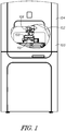
- Figure 1 shows one example of a testing instrument assembly 100.
- the testing instrument assembly 100 includes an instrument chamber 102 formed by an instrument housing 104.
- the instrument chamber 102 includes a testing instrument 106 provided therein.
- the testing instrument 106 includes a probe configured to extend through an environmental conditioning assembly 108, for instance through an enclosure housing 110, and accordingly engage and measure characteristics of a sample positioned within the housing 110.
- the environmental conditioning enclosure 108 is shown below the testing instrument 106.
- the environmental conditioning assembly 108 includes the enclosure housing 110 providing an environmental cavity therein.
- the environmental cavity provides a space for a stage as well as a sample positioned on the stage. That is to say, the sample is positioned within the environmental cavity and is accordingly surrounded by the walls of the enclosure housing 110.
- the enclosure housing 110 is clustered around the sample positioned within the enclosure housing 110 and accordingly a perimeter of the enclosure housing such (e.g., a cavity perimeter) is immediately adjacent to and surrounds the sample to minimize the volume of the environmental cavity relative to a volume of the instrument chamber 102.
- the environmental conditioning assembly 108 provides a conditioned localized environment for the sample therein.
- the instrument chamber 102 has a volume much larger than the volume of the environmental cavity within the enclosure housing 110. Accordingly, the environmental cavity of the enclosure housing 110 is quickly conditioned, including, but not limited to, heating, cooling or conditioning with one or more fluids (e.g., gases or liquids) and the like to provide a desired environment for a sample during testing (e.g., with the testing instrument 106).
- the environmental conditioning assembly 108 provides a localized environment isolated from the remainder of instrument chamber 102. Accordingly, heating, cooling, environmental conditioning and the like are localized to the sample and accordingly are not distributed throughout the instrument chamber 102.
- the sample within the enclosure 108 is isolated from an exterior environment including undesired conditions and fluctuations for instance changes in temperature, humidity, atmosphere composition or the like in the area surrounding the testing instrument assembly 100 (and within the instrument chamber 102). Testing of the sample is thereby readily conducted under one or more desired environmental conditions without interaction with the surrounding environment including the instrument chamber 102 or an environment surrounding the testing instrument assembly 100 (e.g., ambient atmosphere or the like).
- the environmental conditioning assembly 108 includes an enclosure housing 110.
- the enclosure housing 110 includes a bottom jacket 200 and a top jacket 202 coupled together to form the environmental cavity 206 therein.
- the enclosure housing 110 is coupled with a base plate 204.
- the base plate provides a support to the enclosure housing 110, for instance, by way of one or more posts (e.g., jacket supports that support the bottom jacket 200 and accordingly support the remainder of the enclosure housing 110).
- the housing 110 (e.g., the enclosure housing) includes a testing instrument access port 218 extending to the environmental cavity 206 and providing access to a sample within the cavity.
- the testing instrument access port 218 is sized and shaped to permit the passage of an instrument, such as a probe of the testing instrument 106 therethrough.
- the testing instrument access port 218 is dimensioned to facilitate free movement of a probe within the port (e.g., vertically along a Z axis and optionally along one or more of X or a Y lateral axes). Accordingly, the access port 218 provides a gap between an instrument extending through port and the inner perimeter of the port.
- the testing instrument access port 218 provides access to the sample, while the remainder of the housing 110 maintains the desired environment within the cavity 206.
- the environmental conditioning assembly 108 for instance through the testing instrument access port 218, provides ready access to a sample with the environmental cavity 206 for one or more testing instruments configured to conduct a variety of tests.
- the testing assembly 106 or another testing assembly used with the environmental conditioning assembly 108 is operable to conduct one or more of micro or nano indentation, compression testing, attractive force measurement testing, scratch testing, wear testing, material fracture testing, in-situ topography imaging, creep testing, dynamic mechanical testing and all within the controlled environment provided by the assembly 108.
- the housing 110 is configured to provide an isolated environment to a sample within the environmental cavity 206.
- heat transfer to and from the environmental cavity 206 is throttled through a combination of one or more of active heating or cooling, material selection of the housing 110 and insulation and minimizing access to the environmental cavity (e.g., through a limited number of orifices or ports).
- the housing 110 includes cooling inlets and outlets 208, 210 in one or both of the bottom and top jackets 200, 202.
- a cooling or heating fluid is provided through the inlets and outlets 208, 210 and corresponding passages extending through one or both of the bottom and top jackets 200, 202.
- the fluid conducted through the inlets and outlets 208, 210 is a cooling fluid configured to accordingly cool the bottom and top jacket 200, 202 for instance to room temperature while the sample within the environmental cavity 206 is heated for instance with one or both of a sample heater or a top heater as described herein.
- the inlets and outlets 208, 210 of the bottom and top jackets 200, 202 are used to conduct a heated fluid through passages in the jackets to maintain the jackets 200, 202 at a desired temperature (e.g., room temperature). Expansion and contraction of the housing 110 (and nearby components of the testing instrument 106) and thermal mechanical drift are accordingly minimized.
- thermal insulation materials such as a ceramic foam is included within the housing 110 to isolate the housing (constructed in one example with copper bottom and top jackets 200, 202) from heating or cooling of the sample within the environmental cavity 206.
- the environmental conditioning assembly 108 includes a plurality of interfaces configured to operate one or more of heaters or sensors positioned within or adjacent to the environmental cavity 206.
- the top jacket 202 includes a top heater interface 212 sized and shaped to provide electrical connection with the top heater associated with the top jacket 202.
- the top jacket 202 includes a sensor interface 214.
- the sensor interface 214 includes one or more thermocouple leads coupled to a thermocouple in the top heater coupled with the top jacket 202.
- the sensor interface 214 is coupled with another temperature sensor (or other type of sensor) provided within the environmental cavity 206.
- the bottom jacket 200 includes in one example a bottom heater interface 216 (and bottom sensor interface). As will be described herein the bottom heater interface 216 is coupled with a sample heater provided with a sample stage.
- the bottom jacket 200 includes another interface, in a similar manner to the top jacket 202, configured to provide a sensor interface to a temperature sensor or other sensor associated the environmental conditioning assembly 108.
- the environmental conditioning assembly 108 includes a baseplate 204.
- One example of the baseplate 204 is sized and shaped for coupling with a stage surface of an overall instrument, such as the testing instrument assembly 100.
- the baseplate 204 provides a solid kinematic base for the housing 110 and accordingly allows for accurate positioning of the environmental conditioning assembly 108 with regard to the testing instrument 106.
- a translational stage e.g., of the testing instrument assembly 100
- the enclosure 108 and the testing instrument access port 218 are movable to accurately align the testing instrument access port with a probe of the testing instrument 106.
- the solid base provided by the baseplate 204 minimizes lateral movement of the testing instrument access port 218 (e.g., shaking caused by translation of the enclosure 108) and ensures that an instrument delivered through the port does not undesirably engage the port perimeter.
- the baseplate 204 is coupled with a static stage of the testing instrument assembly 100 and the testing instrument 106 is otherwise movable relative to the testing instrument access port 218 to align a probe with the access port.
- FIG 3 shows a cross-sectional view of the housing 110 previously shown in Figure 2 .
- the housing 110 includes a sample stage 300 positioned within a portion of the bottom jacket 200.
- the sample stage 300 includes a stage surface 306 sized and shaped to receive a sample thereon.
- the sample stage 300 further includes a sample heater 304 localized to the sample stage 300 (for instance potted within the stage) and thereby able to readily heat a sample positioned on the sample stage 300.
- a bottom insulation ring 308 is in one example interposed between the sample stage 300 and the remainder of the bottom jacket 200 to accordingly throttle heat transfer from the sample stage 300 to the remainder of the bottom jacket 200. Accordingly the sample stage 300 in combination with the sample heater 304 provides localized heating to a sample positioned on the stage surface 306.
- a top heater 312 coupled with the top jacket 202 is provided in close positional relationship relative to the sample stage 300. That is to say, within the environmental cavity 206 the sample heater 304 and the top heater 312 are positioned in close proximity with a sample positioned on the sample stage surface 306. As will be described herein, in one example the sample stage 300 cooperates with the top heater 312 to provide clamping with surface to surface contact for a sample positioned therebetween. Accordingly, a sample positioned between the sample stage 300 and the top heater 312 receives conductive heating from both the top heater 312 and the sample heater 304 to provide consistent thorough heating throughout the sample and accordingly substantially minimize sample temperature gradients.
- the sample heater 304 and the top heater 312 are heated to different temperatures and thereby providing a desired heating gradient within the sample.
- the sample may be tested with either of these scenarios according to a consistent temperature or a desired temperature gradient provided by the sample heater 304 and the top heater 312 according to the desires of the testing technician.
- a top insulation ring 310 is in one example interposed between the top heater 312 and the remainder of the top jacket 202 to accordingly throttle heat transfer from the top heater 312 to the remainder of the top jacket 202.
- the bottom and top insulation rings 308, 310 cooperate to thermally isolate the sample stage 300, the top heater 312 and a sample on the sample stage from the remainder of the environmental conditioning assembly 108. Accordingly, the sample heater 304 provided with the sample stage and the top heater 312 provide localized heating (or cooling) to a sample positioned on the stage surface 306 while the remainder of the housing 110 is insulated from such heater (or cooling).
- the sample heater 304 (and the top heater 312) heat samples within the environmental cavity 206 over a range of temperatures.
- one or more of the sample heater 304 and the top heater 312 are configured to reach temperatures (and accordingly heat samples) of at least 1500 degrees Celsius.
- one or more of the sample heater 304 and the top heater 312 are configured to reach temperatures of 500, 750, 1000, 1200 degrees Celsius or the like.
- the environmental conditioning assembly 108 through one or more mechanisms constrains heating (and cooling as well) to the enclosure cavity 206 through insulation within the cavity 206 (such as foam ceramic insulation found in the bottom and top insulation rings 308, 310), active cooling (or heating) of the housing 110 through the cooling or heating inlets and outlets 208, 210 and passages within the housing. Accordingly, even at the high temperatures generated with the heaters 304, 312 heating is localized to the sample, and heat transfer is substantially throttled to the remainder of the housing 110 as well as the environment exterior to the housing 110.
- a jacket seal 314 is provided around the environmental cavity 206.
- the jacket seal 314 is in one example provided by a deflectable material, such as silicone rubber or another material configured to withstand extremely high temperatures generated within the environmental cavity while at the same time maintaining the seal between the top and bottom jackets 202, 200.
- the jacket seal 314 includes, but is not limited to, silicone, fluorocarbon elastomers, PTFE, flexible metal (e.g., a bellows type seal or the like.
- the jacket seal 314 encircles at least a portion of the environmental cavity 206 and accordingly seals the environmental cavity (excepting the testing instrument access port 218 and the optional environmental conditioning inlets and outlets described herein).
- the enclosure housing is optionally formed as a two part assembly including the bottom and top jackets 200, 202.
- one or more guideposts 320 extending from one or the other of the top or bottom jackets 202, 200 are sized and shaped for reception within corresponding passages 321 provided within the bottom jacket 200.
- the passages 321 include linear bearings. The linear bearings provide a snug movable engagement with the guideposts 320 and thereby constrain movement of the top jacket 202 as the top jacket is coupled with the bottom jacket 200.
- the guidepost 320 are slidably received within the linear bearings of the passages 321 and accordingly guide the top jacket 202 downwardly as the top jacket is lowered into engagement with the jacket seal 314 to close the environmental cavity 206.
- the gradual lowering of the top jacket 202 e.g., with the guideposts 320 and the passages 321) constrains lateral movement of the top jacket 202 and accordingly facilitates downward movement along a Z axis.
- the top heater 312 moves downward toward the sample stage 300 and a sample positioned on the stage surface 306 the top heater 312 is able to engage with the sample provided on the sample stage 300 in surface to surface contact without relative lateral movement between the sample and the top heater 312.
- the sample is accordingly retained between the sample stage 300 and the top heater 312 through vertical clamping with substantially no appreciable lateral movement between either of the samples stage 300 or the top heater 312 relative to a sample clamped therebetween.
- the environmental conditioning assembly 108 provides an expansion and contraction linkage configured to maintain a sample at a desired elevation, for instance, while the sample is heated or cooled at a steady state temperature.
- a desired elevation for instance, while the sample is heated or cooled at a steady state temperature.
- steady state temperatures e.g. 1500 degrees Celsius
- minor fluctuations with regard to voltage applied to the sample heater 304 and the top heater 312 result in corresponding fluctuations of heating of the sample and the sample stage 300.
- the corresponding fluctuations in temperature provide dynamic elevation changes through expansion, contraction, thermomechanical drift and the like to the components of the environmental conditioning assembly 108. Accordingly, measurement errors caused by these fluctuations may be introduced to testing procedures conducted with the testing instrument 106 shown in Figure 1 .
- the expansion and contraction linkage minimizes these elevation changes caused by fluctuation from the steady state temperature.
- the expansion and contraction linkage includes a plurality of components shown in Figure 3 and further described herein.
- the linkage includes an interface member 316 provided between an interface for one or more jacket supports 318 as well as one or more stage supports provided between the sample stage 300 and the interface member 316.
- the jacket supports 318, the interface member 316, as well as the stage supports cooperate during heating or cooling of a sample positioned on the sample stage 300 to correspondingly minimize elevational changes caused by fluctuations from a steady state temperature.
- the environmental condition enclosure 108 facilitates the localized conditioning of an environment around a sample, for instance, a sample positioned on the sample stage 300.
- the environmental cavity 206 provides a compact localized environment allowing for one or more of heating or cooling of a sample positioned on the sample stage 300, as well as the introduction of one or more conditioning fluids through one or more ports provided within the housing 110.
- an environmental conditioning inlet 322 is provided in one or more of the bottom and top jackets 200, 202.
- the environmental conditioning inlet 322 shown in Figure 3 extends to and is communication with the environmental cavity 206 and is accordingly able to deliver one or more gases, fluids or the like (inert, reactive, heated, cooled or the like) to the environmental cavity 206.
- gases, fluids or the like inert, reactive, heated, cooled or the like
- the introduction of these fluids conditions the environment within the environmental cavity 206 according to the desired testing parameters.
- the top jacket 202 as shown in Figure 3 includes an environmental conditioning outlet 324.
- the environmental conditioning outlet 324 provides a return outlet for fluids delivered into the environmental cavity 206, for instance by way of the environmental conditioning inlet 322 previously described.
- a gas delivery channel 326 is provided along the top jacket 202 to provide inert gas delivery to the testing instrument access port 218.
- the inert gas delivery conditions the environment local to the testing instrument access port 218 as well as an instrument probe extending therethrough.
- the gas delivery channel 326 is used in at least one example to condition fluids exiting the environmental cavity 206 to substantially prevent undesirable cooling or heating of a probe shaft or a transducer coupled with the probe shaft otherwise caused by heating or cooling within the environmental cavity 206.
- the environmental conditioning inlet 322 is configured to provide a flow of an inert gas into the environmental cavity 206 including, but not limited to, argon, nitrogen or some combination of gases such as argon and hydrogen.
- the inert gas is provided to the environmental cavity 206 and accordingly the sample disposed therein to provide a non-oxidizing environment for the sample.
- high temperatures e.g., 1500 degrees Celsius. In an otherwise ambient atmosphere high temperatures may oxidize the sample and accordingly undesirably change its mechanical properties prior to testing with the testing instrument 106 shown in Figure 1 .
- the environmental conditioning inlet 322 provides one means for introducing inert gases and other environmental control fluids into the environmental cavity 206.
- the environmental conditioning inlet 322 provides an inert gas as described above.
- the inert gas 322 provides one or more of a heating or cooling fluid to the environmental cavity 206 that correspondingly heats or cools the environment provided within the environmental cavity 206 while at the same time also heating or cooling the sample positioned on the sample stage 300.
- the environmental conditioning outlet 324 provided optionally in the top jacket 202 is used in one example to remove fluid from the environmental cavity 206.
- the environmental conditioning outlet 324 and the environmental conditioning inlet 322 cooperate to provide a flow of fluids into the environmental cavity 206 throughout a testing procedure for a sample positioned on the sample stage 300.
- the environmental conditioning inlet 322 is used to provide other conditioning fluids to the environmental cavity 206.
- the fluid provided to the environmental cavity 206 in one example is a humidified stream of gas provided from a chamber of humidified gas in communication with the environmental conditioning inlet 322.
- the gas delivery channel 326 is configured to provide a flow of gas to the testing instrument access port and accordingly interrupts a flow of fluid from the environmental cavity 206 otherwise extending through the testing instrument access port 218 possibly rising along a probe shaft toward a transducer of the testing instrument 106 shown in Figure 1 .
- the gas delivery channel 326 in one example provides a stream of cooled gas (such as an inert cooled gas) to the testing instrument access port 218 to substantially interrupt and prevent the upward flow of heated gases along a probe shaft. By interrupting the flow of heated gases along the probe shaft corresponding heating of sensitive instrumentation and transducers within the testing instrument 106 is substantially avoided.
- the environmental conditioning assembly 108 provides a large temperature drop between the sample stage 300 and the top heater 312 to the bottom and top jackets 200, 202.
- the temperature drop at the interface of the environmental cavity 206 to the housing 110 minimizes thermal expansion (or contraction with cooling) of the heating stage during the heating operation. Further, a steep temperature drop through the housing 110 also reduces the overall heated volume of the enclosure 108 and correspondingly the power needed for heating. Further still, by minimizing the heating (or cooling) of the enclosure 110 thermomechanical drift of the enclosure 108 is also minimized.
- a steep temperature drop is realized by providing a large thermal resistance through the enclosure 108 using one or more of the bottom and top insulating rings 308, 310 or the heating or cooling inlets and outlets 208, 210 shown in Figure 2 .
- the sample stage 300 is seen from below thereby exposing the sample heater 304 as well as a plurality of pin recesses 402 arranged around the sample stage 300.
- the sample heater 304 includes a heating element extending between two or more heating element leads 406.
- the sample heater 304 (the heating element) is a wire coil configured for potting within the sample stage 300.
- the sample heater 304 accordingly provides heating to the sample stage 300 in a distributed fashion across the stage surface 306 to accordingly heat a sample positioned thereon.
- a stage thermocouple 410 is also provided with the sample stage 300.
- Thermocouple leads 408 extend from the thermocouple 410 for coupling with an interface extending from the bottom jacket 200 shown in Figure 2 .
- the heating element leads 406 are coupled with a bottom heater interface 216 as shown in Figure 2 .
- the pin recesses 402 constrain heat transfer by limiting the interface between the sample stage 300 and the underlying stage supports.
- the pin recesses 402 each have a tapered shape that provides two point contact (as opposed to surface to surface contact) between the sample stage and a stage support.
- the sample stage 300 includes a plurality of pin recesses 402.
- the tapered configuration of each of the pin recesses 402 is sized and shaped to receive a corresponding stage support therein.
- the tapered pin recesses 402 provide for at least two point engagement with each of the respective stage supports and accordingly provide stable support to the sample stage 300 at each of at least three locations along the stage.
- three pin recesses 402 are provided on the sample stage 300 to provide three point support for the sample stage 300 and accordingly a stable kinematic surface for the positioning and testing of samples on the stage surface 306.
- the sample stage 300 has dual thicknesses.
- a first thickness 412 is measured between the stage surface 306 and an opposed stage surface 400 and a second thickness 414 is measured between the stage surface 306 and a recess trough 404 of the pin recess 402.
- the second smaller thickness 414 of the sample stage 300 is used in one example to minimize the effect of thermomechanical drift and expansion or contraction of the sample stage 300 on testing of a sample coupled with the sample stage 300.
- the second thickness cooperates with operation of the expansion and contraction linkage described herein.
- the second thickness 414 corresponding to the distance between the recess trough 404 and the stage surface 306 substantially minimizes the expansion and contraction of the sample stage 300 during heating.
- any expansion or contraction of the sample stage 300 as it applies to elevation changes of the sample is limited to the second thickness 414 (and not the overall larger first thickness 412).
- the remainder of the sample stage for instance, that portion of the stage 300 below the second thickness (e.g., the remainder of the first thickness) is substantially ignored during expansion or contraction as it extends remotely relative to the stage supports and otherwise provides no additive or subtractive elevation to the sample positioned on the stage surface 306.
- the second thickness 414 is about zero (0) millimeters as the recess trough 404 is positioned immediately adjacent to or coincident with the stage surface 306.
- the recess trough 404 opens onto the stage surface 306 thereby accordingly positioning an appropriately sized stage support positioned within the pin recess 402 immediately adjacent to the stage surface 306.
- the sample heater 304 is installed with the sample stage 300 by potting a heater wire into grooves on the back side of the sample stage 300.
- the grooves are optionally formed between the housings for each of the pin recesses 402.
- the sample stage 300 is constructed with, but not limited to, aluminum nitride.
- Figure 4 shows the coiled heater wire of the sample heater 304 along the sample stage 300.
- the thermocouple 410 (such as a .005" wire diameter Type K; Part number CHAL-005 from Omega) is also potted within the groove.
- the heater wire is made from a material such as Nichrome or Kanthal configured to withstand high temperatures (e.g., temperatures of at least 1500 degrees Celsius) with minimal oxidation.
- a refractory coating is optionally used to coat the heating element wires.
- the heater wire diameter of the sample heater 304 is between about 0.003 to 0.0035 inches, and the heater wire length is selected to provide a resistance of about 25 Ohms.
- the sample heater 304 (coiled heater wire) is attached to the larger heating element leads 406 with a crimping bead.
- the heating element leads 406 are also constructed with Nichrome or Kanthal are several times larger than the heater wire used in the sample heater 304 to minimize the resistive heating in the lead wires.
- FIG 5 shows one example of a top heater 312 (previously shown in Figure 3 ).
- the top heater 312 includes a plurality of features similar in at least some regards to the sample stage 300 previously shown in Figure 4 .
- the top heater 312 includes a potted heating element 502.
- the heating element 502 in one example includes a wire coil coupled with heating element leads 504 extending away from the top heater 312 as shown in Figure 5 .
- a temperature sensor such as a top heater thermocouple 506 is also positioned within the top heater 312.
- Thermocouple leads 508 extend away from the top heater thermocouple and are configured for coupling with the corresponding sensor interface 214 shown in Figure 2 .
- the heating element leads 504 coupled with the top heater 312 are correspondingly configured for coupling with the top heater interface 212 also shown in Figure 2 .
- the top heater 312 cooperates with the sample stage 300 to clamp a sample positioned therebetween in surface to surface contact.
- a clamping surface 500 is provided on the top heater 312.
- the clamping surface 500 is sized and shaped to correspondingly engage with the sample position on the sample stage 300.
- the top jacket 202 descends relative to the bottom jacket 200 until the clamping surface 500 engages with the sample and accordingly clamps the sample between the clamping surface 500 and the sample stage 300.
- the descending top jacket 202 in one example engages with the jacket seal 314 extending between the top and bottom jackets 202, 200 to close the environmental cavity 206 and thereby provide the isolated environment for the sample within the environmental cavity 206.
- the top heater 312 includes one or more fluid channels 510 extending across a portion of the top heater 312, for instance through the clamping surface 500. As shown in Figure 5 , the fluid channels 510 extend through the top heater 512 after extending laterally across the top heater toward the clamping surface 500. That is to say, the fluid channels 510 extend upwardly through the top heater 312 and are accordingly in communication with the testing instrument access port 218.
- the environmental conditioning inlet 322 including one or more of heated or cooled fluids, environmental conditioning fluids, and the like
- these fluids are delivered through the fluid channels 510 to accordingly condition substantially the entire environment of the environmental cavity 206 including that portion of the environmental cavity immediately above the sample on the sample stage 300.
- the conditioning fluids are thereafter delivered upwardly in one example through the testing instrument access port 218 and are removed with the environmental conditioning outlet 324.
- the top heater 312 is constructed with, but not limited to, aluminum nitride. As shown in Figure 3 , the top heater 312 is optionally surrounded by the insulation ring 310, for instance a ceramic foam material, such as Cotronics Rescor 310. The top heater 312 is retained within the top jacket 202 by fasteners, such as screws, pins, rivets or the like. Optionally, the fasteners are made of Zirconia having a low thermal conductivity to minimize heat transfer to the jacket 202.
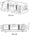
- FIG 6A is a cross-sectional view of the environmental conditioning assembly 108 previously described herein.
- the top jacket 202 is removed to expose the bottom jacket 200 coupled with the base plate 204.
- the bottom jacket 200 is suspended above the base plate 204 with a plurality of jacket supports 318 (e.g., interface supports).
- the jacket supports 318 have a length greater than the distance between the support interface 612 and the bottom of the bottom jacket 200. Accordingly, the jacket supports 318 suspend the bottom jacket 200 as well as the remainder of the enclosure housing 110 above the base plate 204.
- the housing 110 is substantially isolated from the remainder of the environmental conditioning assembly 108 by way of the jacket supports 318.
- the jacket support 318 accordingly throttle heat transfer from the housing 110 to the remainder of the environmental conditioning assembly 108, such as the base plate 204 as well as any features coupled with the base plate (for instance, one or more components of the testing instrument assembly 100).
- the expansion and contraction linkage 600 includes the jacket supports 318, an interface member 316, and the plurality of stage supports 602 extending between the interface member 316 and the sample stage 300.
- the jacket supports 318 extend from the base plate 204 to a support interface 612 of the interface member 316.
- the interface member 316 extends from the support interface 612 to a stage interface 614 coupled with the stage support 602.
- the stage supports 602, for instance support pins for the stage 300 extend upwardly from the stage interface 614 to support the stage 300.
- the stage supports 602 are received within the pin recesses 402 including recess troughs 404.
- the expansion and contraction linkage 600 accordingly provides a linkage extending from the sample stage 300 to the base plate 204.
- the expansion and contraction linkage 600 maintains the elevation of the sample stage 300 and a sample thereon substantially static while the sample stage and the sample experience fluctuations in temperature that would otherwise cause elevational changes (and corresponding measurement error with an instrument engaged with the sample).
- the interface member 316 is incorporated into and is part of the bottom jacket 200.
- the interface member 316 is a portion of the bottom jacket 200 between the support interface 612 and the stage interface 614.
- the stage interface 614 is recessed relative to the support interface 612.
- the interface member 316 is separate from the bottom jacket 200.
- the interface member 316 is a separate component extending between the support interface 612 and the stage interface 614. Accordingly, in such an example the interface member 316 is a separate component from the bottom jacket 200 and is dedicated to the expansion and contraction of the linkage 600.
- the jacket supports 318 include a column body 606 extending between the base plate 204 and the support interface 612.
- the column body 606 outer diameter is smaller than a support cavity 608 inner diameter sized and shaped to receive the jacket supports 318 therein.
- the column body 606 when positioned within the support cavities 208 (and centered, for instance by one or more support posts 604, such as screws, pins or the like coupled with the jacket 200 and the base plate 204) provides a gap between the jacket support 318 and the bottom jacket 200.
- the gap between the jacket support 318 and the remainder of the bottom jacket 200 allows for independent movement of each of the jacket supports 318 as well as the interface member 316 during operation of the expansion and contraction linkage 600. Stated another way, the jacket 200 is isolated from at least the jacket supports 318 and accordingly does not interfere with expansion or contraction of the supports.
- the bottom jacket 200 includes linear bearings sized and shaped to receive the guidepost 320 therein.
- the cooperation of the guidepost 320 and the linear bearings 616 e.g., within the passages 321) allows the top jacket 202 to easily descend toward the bottom jacket 200 due to gravity and accordingly close the environmental cavity 206.
- the guideposts 320 cooperate with the bottom jacket 200 to suspend the top jacket 202 upon the bottom jacket and accordingly ensure that the top jacket 202 does not interfere with operation of the expansion and contraction linkage 600.
- the expansion and contraction linkage 600 is shown in a cross-sectional view.
- the expansion and contraction of the linkage 600 includes one or more stage supports 602, the interface member 316 coupled with the stage supports 602, and the jacket supports 318 also coupled with the interface member 316.
- the interface member 316 includes two components, for instance the support interface 612 sized and shaped to engage with the jacket supports 318 and the stage interface 614 sized and shaped to engage with the stage support 602.
- the stage interface 614 as shown is recessed a length 601 (e.g., about 1 mm) relative to the support interface 612.
- the jacket supports 318 and the stage supports 602 have corresponding lengths that cooperate with the recessed stage interface 614 to ensure a net elevation change of about 0 mm with expansion and contraction of the linkage 600 through heating or cooling within the housing 110 (of the housing itself), as described herein.
- the jacket supports 318 have lengths 603 of about 25 mm
- the stage supports 602 have lengths 605 of around 9.5 mm. The lengths in combination with the materials chosen for the components of the linkage minimize any elevation change.
- the recessing of the stage interface 614 relative to the support interface 612 provides a cooperative counter movement to corresponding expansion and contraction of each of the stage supports 602 and the jacket supports 318.
- the stage supports 602 and the jacket supports 318 receive at least some measure of heat transfer from the sample stage 300 and accordingly expand upwardly relative to the stage interface 614 and the base plate 204, respectively.
- the expansion of the jacket supports 318 biases the support interface 612 upwardly.
- the interface member 316 expands in an opposite direction relative to the expansion of each of the stage supports 602 and the jacket supports 318 because stage interface 614 is relative to the support interface 612.
- the interface member 316 expands downwardly relative to the upward expansion of the stage supports 602 and the jacket supports 318.
- the converse occurs with cooling in the environmental cavity. That is to say, the stage supports 602 and the jacket supports 318 contract in a first direction, while the interface member 316 contract in an offsetting second direction. Accordingly, the net translation of the expansion and contraction linkage 600 whether during heating or cooling at a steady state temperature is a net elevation change of 0 with fluctuations from the steady state temperature.
- the expansion and contraction linkage 600 operates to offset expansion or contraction otherwise generated by these temperature fluctuations at the stage surface 306. Accordingly, the sample elevation on the sample stage 300 as shown in Figure 6A remains substantially static even with fluctuations in temperature relative to a steady state temperature (whether heated or cooled). Measurements, for instance measurements conducted with the testing instrument 106 of the testing instrument assembly 100, are thereby conducted with a substantially static sample (when heated or cool) as opposed to a sample that moves based on temperature fluctuations from a desired steady state temperature.
- Figure 7 shows a schematic view of the expansion and contraction linkage 600 previously described and shown in Figures 6A and 6B .
- the left most arrows of each pair of arrows associated with the stage supports 602, interface member 316, and the jacket supports 318 corresponds to of at least the sample stage 300 along with incidental heat transfer to the remainder of the housing 110.
- the right most arrows of the paired arrows for each of the stage supports 602, the interface member 316 and the jacket supports 318 corresponds to cooling of the stage 300 and optionally the environmental cavity 206 for instance through the provision of a chilled or cooled fluid provided by the environmental conditioning inlet 322 (as shown in Figure 3 ).
- the downward movement of the interface member 316 in the heated condition offsets the corresponding upward movement provided by the stage supports 602 and the jacket supports 318 caused by expansion of each of these components.
- the upward relative movement of the interface member 316 offsets the corresponding downward movement of the stage support 602 and the jacket supports 318 during cooling within the environmental cavity 206 caused by contraction of each of these components of the linkage 600.
- each of the stage supports 602, jacket supports 318, as well as the interface member 316 are chosen according to their thermal mechanical properties including their coefficients of thermal expansion, thermal conductivities, and the like.
- the interface member 316 is able to offset expansion and contraction of both of the stage supports 602 and the jacket supports 318 during either of heating or cooling.
- the interface member 316 moves in an opposite direction relative to the stage supports 602 and the jacket supports 318 and is able to offset expansion or contraction of these features and accordingly maintain the stage surface 306 with the sample thereon at a desired elevation (for instance as the state 300 is subjected to temperature variations from a steady state temperature).
- the sample stage 300 includes the recess troughs 404 positioned immediately adjacent to the stage surface 306 (also shown in Figure 4 ). Placing the recess troughs 404 in close proximity to the stage surface 306 ensures expansion or contraction of the sample stage 300 and a corresponding elevation change of the surface 306 is substantially mitigated or minimized by the close and intimate engagement of the stage supports 602 at the stage surface 306. That is to say, the second thickness 414 (also shown in Figure 4 ) is substantially minimized by providing the recess troughs 404 immediately adjacent to the stage surface 306 or coincident with the stage surface 306.
- expansion or contraction of the sample stage 300 during heating or cooling is correspondingly minimized with regard to its effect on the sample elevation (e.g., has a minimal effect on operation of the expansion and contraction linkage 600).
- the expansion and contraction linkage 600 as described herein is thereby able to maintain the stage surface 306 and a sample positioned thereon at a substantially static elevation even with temperature fluctuations from a steady state temperature.
- the expansion and contraction linkage 600 shown in Figures 6A , B is a demonstrative example having the characteristics provided in the expansion and contraction equations provided below.
- the interface member 316 minimizes the Z-Displacement of the stage supports 602 and the jacket supports 318 caused by heating or cooling relative to a steady state temperature.
- the interface member 316 changes temperature ( ⁇ T)
- the average temperature change of the stage supports 602 is about half of the temperature change of the interface member 316 because the temperature at the top end of the stage supports is controlled by the sample stage 300 temperature.
- the average temperature change of the jacket supports 318 is also about half of the temperature change of the interface member 316 (e.g., optionally the bottom jacket 200) because the temperature of the bottom ends of the jacket supports 318 is determined by the temperature of the underlying base plate 204.
- the Z-displacement caused by a temperature change in the environmental conditioning assembly 108 (and attenuated by the expansion and contraction linkage 600) is the sum of the Z-displacements of the stage supports 602, the interface member 316 and the jacket supports 318. The dimensions and materials for each these components are selected so that the Z-displacements sum to approximately zero.
- the jacket supports 318 are made of a low coefficient of thermal expansion material including, but not limited to, Invar.
- the interface member 316 (e.g., the bottom jacket 200) is made of copper and has a moderate coefficient of thermal expansion relative to the other components.
- the stage supports 602 are constructed with, but not limited to, Quartz having a low coefficient of thermal expansion relative to at least interface member 316.
- FIG 8 shows a schematic view of a portion of the environmental conditioning assembly 108.
- the top jacket 202 is coupled along a portion of a sample 806 provided on the sample stage 300.
- the sample 806 is clamped between the top jacket 202, for instance the top heater 312, and the sample stage 300 including the sample heater 304 therein.
- the clamping engagement of the sample 806 provides surface to surface contact with the sample 806 and accordingly facilitates conductive heat transfer at both opposed surfaces of the sample 806 corresponding to the interfaces with the top heater 312 and the stage surface 306 (the sample heater 304 is optionally within the sample stage 300).
- the top jacket 202 includes one or more guideposts 320 sized and shaped for reception within passages 321 of the bottom jacket 200.
- linear guide bearings 616 are provided in the passages 321 and are configured to snuggly receive the guideposts 320 therein and guide the top jacket 202 along a substantially vertical axis into engagement with the sample 806 as shown in Figure 8 . Accordingly, as the top heater 312 engages with the sample 806 (e.g., at the clamping surface 500 previously shown in Figure 5 ) the top heater 312 provides substantially no lateral movement to the sample 806.
- the sample 806 is stably engaged by the top heater and clamped between the sample stage 300 and the clamping surface 500 with substantially no lateral movement imparted to the sample 806.
- a fixation feature such as a spring clamp or the like is applied to the top and bottom jackets 202, 200 to further immobilize the clamping engagement between the top heater 312 and the sample stage 300.
- the construction of the bottom and top jackets 200, 202 for instance with copper plates affirmatively clamps the sample 806 between the top heater 312 (e.g., included in the top jacket 202 and the sample stage 300 provided in the bottom jacket 200) due to gravity.
- the top heater 312 in at least one example includes a plurality of fluid channels 510.
- the fluid channels 510 allow for communication between the testing instrument access port 218 and the remainder of the environmental cavity 206.
- an environmental conditioning fluid is supplied to the environmental cavity 206, for instance by the environmental conditioning inlet 322 shown in Figure 3
- the environment provided in the environmental cavity 206 extends into the testing instrument access port 218 (e.g., the portion of the environmental cavity 206) immediately above the sample 806. Accordingly, the entirety of the sample 806 is maintained within the environment of the environmental cavity 206.
- a probe 800 for instance of the testing instrument 106 shown in Figure 1 , extends through the testing instrument access port 218 to engage with the sample 806.
- the probe 800 engages the sample 806 within that provided environment (e.g., heated, cooled, conditioned with one or more fluids or the like). Stated another way, the testing instrument access port 218 in in communication with and is part of the environmental cavity 206.
- the clamping engagement between the top heater 312 and the stage 300 is configured to provide consistent reliable heating throughout the sample 806.
- the surface to surface contact provided by the clamping engagement readily conducts heat into the sample 806.
- the top heater 312 and the sample heater 304 are heated to the same temperature the sample 806 has a substantially minimized temperature gradient between the opposed surfaces engaged with the top heater 312 and the sample stage 300.
- the top heater 312 and the sample heater 304 are heated to varying degrees. For instance, the top heater 312 is heated to a first temperature while the sample heater 304 is heated to a second temperature different from the first temperature of the top heater 312.
- the clamped sample 806 is provided with a gradient of temperatures from its top most surface adjacent to the clamping surface 500 to its bottom most surface adjacent to the stage surface 306. Accordingly where it is desirable to measure properties of the sample according to temperature gradients therein such a temperature gradient is provided by the clamping engagement achieved with engagement of the top heater 312 and the sample stage 300 with the sample 806.
- the probe 800 includes one or more electrical contacts 808 at the probe tip 804.
- the sample stage 300 includes one or more corresponding electrical contacts 810.
- the electrical contacts 808, 810 are configured to engage the sample 806 held in clamping engagement between the top heater 312 and the sample stage 300.
- the testing instrument 106 previously shown in Figure 1 is used in cooperation with the sample stage 300 to perform one or more electrical characteristic tests of the sample 806. For instance, a potential is applied across the contact 808 of the probe 800 and the contact 810 of the sample stage 300 to accordingly measure one or more electrical characteristics of the sample 806 including but not limited to resistivity, conductivity, and the like.
- FIG 9 shows a schematic example of the environmental conditioning assembly 108.
- the environmental conditioning assembly 108 provides a housing 110 having an environmental cavity 206.
- the housing 110 includes bottom and top jackets 200, 202 coupled along a jacket seal 314.
- the environmental cavity 206 substantially isolates a sample within the environmental cavity while still providing access through a testing instrument access port 218. Additionally, the environmental cavity localizes a small environment to the area immediately adjacent to the sample, for instance by clustering the cavity perimeter of the enclosure housing 110 closely around the sample.
- the instrument chamber volume 102 is significantly larger than the corresponding volume of the environmental cavity 206.
- conditioning of the environment within the environmental cavity 206 is readily accomplished through one or more inlets or outlets providing environmental conditioning fluid as well as localized heating or cooling of the sample positioned on the sample stage 300 without corresponding heating and temperature fluctuations caused in larger environments (e.g., volumes larger than the cavity 206).
- an environmental conditioning system is provided.
- the environmental conditioning system extends through the environmental cavity 206, for instance by way of the environmental conditioning inlet 322 and one or more environmental conditioning outlets 324, 900.
- an environmental conditioning outlet 324 is provided within the top jacket 202, for instance adjacent to the testing instrument access port 218.
- the environmental conditioning outlet 324 optionally applies a negative pressure (e.g., a vacuum) within the testing instrument access port 218 and accordingly prevents the egress of fluids from within the environmental cavity 206.
- an environmental conditioning outlet 900 is provided on the opposed side of the environmental cavity 206 relative to the environmental conditioning inlet 322.
- the environmental conditioning outlet 900 facilitates the delivery of environmental conditioning fluids within the environmental cavity 206 and across a sample on the sample stage 300 to further ensure the environmental cavity 206 and the sample are exposed to heating or cooling fluids and any other environmental conditioning fluids delivered between the inlet 322 and the outlet 900.
- a coolant or heating fluid source 904 is provided in communication with the environmental conditioning inlet 322.
- the coolant or heating fluid source 904 includes a cooled or heated source of gas, liquid or the like provided at a desired temperature.
- the fluid is delivered by way of a conditioning pump 908 in communication with the environmental conditioning inlet 322.
- the conditioning pump 908 includes, but is not limited to, a pump, blower, fan, dripping mechanism, or the like.
- the environmental conditioning loop includes a conditioning fluid source 906 (e.g., in communication with the conditioning pump 908).
- the conditioning fluid source 906 includes, but is not limited to, one or more reservoirs of inert gas, air, reactive fluids, liquids, humidified gases and the like.
- the conditioning fluid source 906 includes a source of inert gas, such as a mixture of argon and hydrogen. As the inert gas is pumped (with the conditioning pump 908) into the environmental cavity 206 the surrounding environment of a sample therein is accordingly filled with the inert gas.
- the environment within the environmental cavity 206 correspondingly elevates in temperature for instance to a temperature of 1500 degrees Celsius.
- the inert gas present in the environmental cavity 206 oxidation of a sample on the sample stage 300 is substantially minimized. Accordingly, the testing of the sample (e.g., with the probe 800) is carried out in this elevated temperature without risk of oxidation of the sample therein.
- the conditioning fluid source 906 provides a source of humidified gas for instance a bubbled inert gas delivered through a bath of chilled water.
- the conditioning fluid source 906 provides a source of a reactive fluid configured to initiate a chemical reaction with the sample in the environmental cavity 206. Accordingly by delivering the reactive fluid into the environmental cavity 206 the reaction with the sample is localized and accordingly the probe 800 is able to examine the reacting sample within a small localized environment substantially isolated from environmental factors exterior to the environmental conditioning assembly 108.
- one or both of the environmental conditioning outlets 324, 900 are in communication with an extraction pump 912 and an extraction reservoir 910.
- the extraction pump 912 provides a negative pressure at one or more of the environmental conditioning outlets 324, 900.
- the environmental conditioning fluid provided by way of the environmental conditioning inlet 322 is drawn through the environmental cavity 206.
- a flow of environmental conditioning fluid is delivered at a constant flow rate through the environmental cavity 206 to substantially maintain the environment around the sample positioned on the sample stage 300.
- one or more of heating or cooling of the sample is provided and continuously maintained throughout a testing procedure according to the needs of the procedure (e.g., cooling to subfreezing temperatures or heating to temperatures approaching 1500 degrees Celsius).
- the environmental conditioning outlet 324 is positioned within the testing instrument access port 218 the outlet 324 is configured to withdraw any fluids provided by way of the environmental conditioning inlet 322 prior to egress of the fluid through the access port 218.
- a sample within the environmental conditioning assembly 108 must be maintained at the desired temperature during testing, for instance while engaged by the probe 800.
- a desired temperature e.g. 1500 degrees Celsius
- the temperature distribution from the sample to the probe 800 depends on the relative heat resistance through these components.
- the narrow heat flux through the very small contact area e.g., where the probe tip 804 engages the ample
- provides a large thermal resistance thermal resistance is inversely proportional to the area perpendicular to the heat flux).
- the large heat resistance near the contact area causes a large temperature drop at the contact area of the sample and in the nearby vicinity.
- the temperature of the contact zone upon engagement with the probe tip 804 is not the same as the overall sample temperature.
- the probe 800 (e.g., of the testing instrument 106 shown in Figure 1 ) extends into the environmental cavity 206 by way of the testing instrument access port 218.
- the probe tip 804 is correspondingly heated to an identical temperature.
- the probe tip 804 is readily heated to an identical temperature to the sample positioned on the sample stage 300.
- the bottom heater 304 and the sample positioned therebetween an environment is created locally around the probe tip 804 that correspondingly heats the probe tip 804, by radiation, to a temperature substantially identical to that of the sample on the sample stage 300.
- an environmental conditioning fluid such as heating or cooling fluids are provided through the environmental conditioning inlet 322 (or a fluid is heated by one of the heaters 304, 312) the environment within the environmental cavity 206 is correspondingly heated or cooled to a desired temperature.
- the probe tip 804 positioned within the environment of the environmental cavity 206 the probe tip is correspondingly convectively heated or cooled to the same desired temperature.
- the probe tip 804 upon engagement between the probe tip and the sample positioned on the sample stage 300 the probe tip 804 (when previously positioned within the environmental cavity 206) is at a substantially identical temperature. Accordingly heat transfer between the probe tip 804 and the sample on the sample stage 300 is substantially minimized. Instead, each of the probe tip 804 and the sample are at substantially the same temperature and accordingly the sample is tested at that elevated temperature without corresponding heat transfer from or to the probe tip 804. The sample thereby remains at the desired temperature throughout the testing procedure.
- the environmental conditioning assembly 108 includes a gas delivery channel 326 configured to provide a flow of gas to the probe 800.
- the probe 800 is coupled with sensitive electronics and measurement equipment in the testing instrument 106 (e.g., capacitive transducers, sensors and the like) that are sensitive to changes in temperature for instance provided by heating of the sample on the sample stage 300.
- the gas delivery channel 326 in one example interrupts the flow of heated fluid upwardly from the environmental cavity 206 (e.g., along the probe shaft of the probe 800) and toward the transducers of the testing instrument 106.
- the gas delivery channel 326 is coupled with an isolation fluid pump 912 and an isolation fluid source 914.
- the isolation fluid source 914 provides a heated or cooled flow of fluid (or optionally a room temperature flow of gas) that is pumped by way of the isolation fluid pump 912 to the transversely mounted gas delivery channel 326.
- the flow of gas from the gas delivery channel 326 crosses the probe shaft 802 of the probe 800 and accordingly interrupts the upward flow of any heated fluids from the testing instrument access port 218. That is to say, incidental flow of environmental conditioning fluids (such as gases, heated or cooled fluids, and the like) rising from the testing instrument access port 218 is interrupted by the flow of fluid from the gas delivery channel 326. Accordingly sensitive electronics, transducers and the like associated with the testing instrument 106 are preserved from the heated or cooled environment of the environmental cavity 206.
- Figure 10 shows one example of a method 1000 for using an environmental conditioning assembly, such as the environmental conditioning assembly 108 shown in Figures 1 and 2 .
- an environmental conditioning assembly such as the environmental conditioning assembly 108 shown in Figures 1 and 2 .
- reference numerals The reference numerals provided are exemplary and are not exclusive.
- the features components, functions, steps and the like described in the method 1000 include but are not limited to the corresponding numbered elements, other corresponding features described herein (both numbered and unnumbered) as well as their equivalents.
- the method 1000 includes positioning a sample such as the sample 806 on a sample surface (e.g., a stage surface 306) of a sample stage 300 within an environmental cavity 206 of a housing 110 (e.g., an enclosure housing 110).
- the cavity perimeter of the housing 110 is clustered around the sample stage 300 and the sample.
- the cavity perimeter corresponds to the inner perimeters of one or more of the top and bottom jackets 202, 200 closely arranged around the sample stage 300. Accordingly, the localized environment provided around the sample is small relative to a relatively open environment, for instance of the instrument chamber 102 shown in Figure 1 .
- the sample is heated or cooled in the environmental cavity 206 to a steady state temperature with a sample heating or cooling system.
- the sample heating or cooling system includes one or more of conductive convective and radiative systems of heating or cooling.
- the sample is conductively heated with a sample heater 304 and optionally a top heater 312 each of which is positioned in close proximity to the sample, for instance in clamping engagement.
- heating or cooling is provided by way of an environmental conditioning fluid delivered for instance through the environmental conditioning inlet 322 and removed through an environmental conditioning outlet (e.g., the outlets 324, 900 shown in Figure 9 ).
- heating or cooling of the sample to the steady state temperature includes the sample experiencing temperature fluctuations above and below the steady state temperature, for instance caused by fluctuations in voltage, fluctuations in temperature in the environmental conditioning fluid and the like.
- the method 1000 includes maintaining a sample elevation and stage surface 306 elevation within the environmental conditioning assembly 108 substantially static with the temperature fluctuations provided during heating or cooling.
- the elevations are maintained statically through expansion and contraction of an expansion and contraction linkage 600 shown in Figures 6A and 6B .
- the expansion and contraction linkage 600 is coupled between the housing 110 and the sample stage 300.
- the method 1000 includes accessing the sample through a testing instrument access port 218 with a probe 800.
- the testing instrument access port 218 extends through the housing 110 and into the environmental cavity 206.
- An access port perimeter of the testing instrument access port extends around the testing instrument positioned within the testing instrument access port and accordingly includes an actuation gap therebetween to facilitate movement of the probe 800, for instance during mechanical testing procedures involving movement of the probe to engage and deform the sample positioned within the environmental cavity 206.
- the testing instrument access port 218 maintains the isolation provided by the environmental cavity 206 to the sample while at the same time allowing interaction between a probe extending from the exterior of the environmental conditioning assembly 108 to the sample positioned within the cavity 206.
- the method 1000 includes clamping a sample, such as the sample 806, between the top jacket and the bottom jacket of the housing 110.
- the top jacket and the bottom jacket 202, 200 include the top heater 312 and the sample stage 300.
- the sample 806 is clamped between the top heater 312 and the sample stage 300 to thereby provide conductive heat transfer from the top heater 312 and the sample stage 300 to the sample 806 from opposing surfaces.
- the environmental conditioning assembly 108 in one example includes an expansion and contraction linkage 600.
- the expansion and contraction linkage 600 includes a first portion that moves in a first direction during heating or cooling and a second portion of the linkage 600 that expands in a second opposed direction during heating or cooling. Accordingly, during heating the first portion expands in the first direction while the second portion expands in a second direction to thereby offset expansion provided in the first direction by the first portion. Conversely with cooling of the sample, (e.g., through the introduction of environmental conditioning fluids configured to cool the environmental cavity 206) the first portion of the expansion and contraction linkage moves in the second direction (opposite to the first direction previously described) and the second portion contracts in the first direction opposed to the first direction the first portion moves.
- the expansion and contraction linkage 600 cooperates by way of the first and second portions to accordingly maintain the sample elevation and the stage surface elevation substantially static in a similar manner to that provided with heating. That is to say, while the sample 806 ( Figure 8 ) is maintained at a desired temperature, for instance a steady state temperature approaching 1500 degrees Celsius or less expansion and contraction, thermo-mechanical drift or the like otherwise caused by temperature fluctuations at the sample 806 and within the environmental cavity 206 are accordingly attenuated with the linkage 600. Stated another way, the expansion and contraction linkage 600 cooperates through a combination of opposed expansion or contraction during temperature fluctuations to accordingly maintain the sample and the stage surface 306 at a substantially static elevation.
- the method 1000 includes heating or cooling the probe 800 extending through the testing instrument access port.
- the instrument probe 800 positioned within the testing instrument access port 218 is heated with one or more of radiative or convective heating and cooling provided by the environment within the environmental cavity 206.
- an environmental conditioning fluid cooled or heated
- the fluid provides convective heat transfer to both the sample 300 as well as the probe 800 and accordingly maintains the probe 800 (e.g., the probe tip 804) at a substantially identical temperature to the temperature of the sample on the sample stage 300.
- the probe tip 804 is heated with radiation based heat transfer. In another example, the probe tip 804 is heated with a combination of radiation and convective heat transfer.
- the method 1000 includes throttling heat transfer between the probe tip 804 and an opposed end of the probe shaft for instance a portion of the probe shaft coupled with sensitive instruments, such as a transducer, sensing devices and the like coupled with the opposed end of the probe shaft 802.
- throttling heat transfer along the probe 800 for instance away from an opposed end of the probe shaft is accomplished with an environmental conditioning outlet 324 extending into close proximity to the testing instrument access port 218.
- the environmental conditioning outlet 324 is in communication with the testing instrument access port 218 and accordingly withdraws fluids such as heated or cooled fluids from within the access port to accordingly attenuate heat transfer upwardly along the probe shaft 802.
- the gas delivery channel 326 also shown in Figure 9 is used to provide a flow of isolation fluid across the probe 800.
- the pressurized flow of isolation fluid for, instance an inert gas that is cooled or maintained at room temperature relative to the heated environment within the environmental cavity 206, interrupts the flow of heat along the probe 800. That is to say, the flow of gas provided by the gas delivery channel 326 is transverse to the probe 800 and accordingly interrupts the flow of heated or cooled fluids upwardly along the probe 800 (and provides convective heat transfer for heat within the probe shaft 802) toward sensitive equipment such as transducers.
- the method 1000 further includes conditioning a localized environment around the sample positioned on the sample stage 300 within the environmental cavity 206.
- the environmental cavity 206 has a first volume and an instrument cavity such as the instrument chamber 102 has a second volume, the second volume being larger than the first volume of the environmental cavity 206.
- the method 1000 further includes in one example testing of a sample within the environmental conditioning assembly 108.
- a probe such as the probe 800 shown in Figures 8 and 9 is introduced through the testing instrument access port 218.
- the probe 800 conducts one or more mechanical testing procedures including engagement of the probe tip 804 with the sample on the sample stage 300.
- Engagement of the probe with the sample stage 300 optionally deforms the sample and allows for the measurement of one or more mechanical properties and characteristics of the sample, including but not limited to, the force applied to the sample, the depth of penetration by the probe tip 804 and corresponding mechanical characteristics such as hardness, the modulus of elasticity or the like.
- testing of the sample within the environmental cavity 206 includes electrically biasing a probe tip 804 for instance with the electrical contact 808 shown in Figure 8 . Additionally the sample stage 300 is also biased by the corresponding electrical contact 810. The sample 806 within the environmental cavity 206 is electrically tested by engaging the probe tip 804 with the sample 806 while the sample is positioned on the stage surface 306. One or more electrical characteristics are measured based on this engagement thereby accordingly determining one or more electrical characteristics of the sample 806
- Method examples described herein can be machine or computer-implemented at least in part. Some examples can include a computer-readable medium or machine-readable medium encoded with instructions operable to configure an electronic device to perform methods as described in the above examples.
- An implementation of such methods can include code, such as microcode, assembly language code, a higher-level language code, or the like. Such code can include computer readable instructions for performing various methods. The code may form portions of computer program products. Further, in an example, the code can be tangibly stored on one or more volatile, non-transitory, or non-volatile tangible computer-readable media, such as during execution or at other times.
- Examples of these tangible computer-readable media can include, but are not limited to, hard disks, removable magnetic disks, removable optical disks (e.g., compact disks and digital video disks), magnetic cassettes, memory cards or sticks, random access memories (RAMs), read only memories (ROMs), and the like.
Landscapes
- Physics & Mathematics (AREA)
- General Physics & Mathematics (AREA)
- Chemical & Material Sciences (AREA)
- Immunology (AREA)
- Biochemistry (AREA)
- General Health & Medical Sciences (AREA)
- Life Sciences & Earth Sciences (AREA)
- Health & Medical Sciences (AREA)
- Pathology (AREA)
- Analytical Chemistry (AREA)
- Engineering & Computer Science (AREA)
- Thermal Sciences (AREA)
- Mechanical Engineering (AREA)
- General Engineering & Computer Science (AREA)
- Chemical Kinetics & Catalysis (AREA)
- Electrochemistry (AREA)
- Investigating Strength Of Materials By Application Of Mechanical Stress (AREA)
- Testing Resistance To Weather, Investigating Materials By Mechanical Methods (AREA)
Claims (18)
- Umweltkonditionierungsanordnung (108) zur Verwendung bei mechanischen Prüfungen auf Mikrometer- oder kleinerer Ebene, welche Umweltkonditionierungsanordnung (108) aufweist:ein Umschließungsgehäuse (110), das einen Umwelthohlraum (206) enthält, welches Umschließungsgehäuse (110) eine Prüfinstrument-Zugangsöffnung (218), die sich durch das Umschließungsgehäuse (110) in den Umwelthohlraum (206) erstreckt, enthält, wobei ein Zugangsöffnungsumfang der Prüfinstrument-Zugangsöffnung (218) sich um ein Prüfinstrument herum erstreckt, das innerhalb der Prüfinstrument-Zugangsöffnung (218) mit einem Betätigungsspalt zwischen diesen positionierbar ist;einen Probentisch (300) innerhalb des Umwelthohlraums (206), welcher Probentisch (300) eine Tischoberfläche zum Stützen einer Probe auf dieser enthält, und ein Hohlraumumfang des Umschließungsgehäuses (110) um den Probentisch (300) herum gruppiert ist;ein Probenheizungs- oder -kühlungssystem, das konfiguriert ist zum Erwärmen oder Kühlen der Probe auf der Tischoberfläche (306) innerhalb des Umschließungsgehäuses (110).
- Umweltkonditionierungsanordnung (108) nach Anspruch 1, bei der das Umschließungsgehäuse (110) konfiguriert ist für die Positionierung innerhalb einer Instrumentenkammer (102) einer Instrumentenanordnung, wobei ein Instrumentenkammervolumen größer als ein Umwelthohlraumvolumen des Umwelthohlraums (206) ist.
- Umweltkonditionierungsanordnung (108) nach Anspruch 1, bei der das Umschließungsgehäuse (110) eine obere Schale (202) enthält, die mit einer unteren Schale (200) gekoppelt ist, und der Probentisch (300) zwischen der oberen und der unteren Schale angeordnet ist, und die obere Schale (202) eine obere Heizvorrichtung (312) enthält, und die obere Schale (202) und die untere Schale (200) konfiguriert sind zum Einklemmen einer Probe zwischen der Probenheizvorrichtung (304) des Probentisches (300) und der oberen Heizvorrichtung (312).
- Umweltkonditionierungsanordnung (108) nach Anspruch 1, aufweisend eine Expansions- und Kontraktionsverbindung (600), welche enthält:ein Schnittflächenteil (316) mit einer Stützschnittfläche (612) und einer Tischschnittfläche (614), die gegenüber der Stützschnittfläche (612) vertieft ist,eine oder mehrere Tischstützen (602), die mit dem Schnittflächenteil (316) in der Tischschnittfläche (614) gekoppelt sind, wobei die eine oder die mehreren Tischstützen (602) mit dem Probentisch (300) gekoppelt sind,eine oder mehrere Schnittflächenstützen, die mit dem Schnittflächenteil (316) in der Stützschnittfläche (612) gekoppelt sind, undin jeder von einer in stabilem Zustand erwärmten oder gekühlten Konfiguration für eine Probe die Expansions- und Kontraktionsverbindung (600) sich ausdehnt beziehungsweise zusammenzieht gemäß Temperaturschwankungen oberhalb und unterhalb einer stabilen Temperatur, und eine Tischoberflächenerhöhung der Tischoberfläche (306) im Wesentlichen statisch bleibt gemäß der Expansion und Kontraktion der Expansions- und Kontraktionsverbindung (600).
- Umweltkonditionierungsanordnung (108) nach Anspruch 4, bei der:die eine oder die mehreren Tischstützen (602) und die eine oder die mehreren Schnittflächenstützen sich mit den Temperaturschwankungen in einer ersten Richtung ausdehnen oder zusammenziehen, unddas Schnittflächenteil (316) zwischen der Stützschnittfläche (612) und der Tischschnittfläche (614) sich mit den Temperaturschwankungen in einer zweiten Richtung, die der ersten Richtung entgegengesetzt ist, ausdehnt und zusammenzieht,wobei die Expansion oder Kontraktion des Schnittflächenteils (316) in der zweiten Richtung mit der Expansion oder Kontraktion der einen oder der mehreren Tischstützen (602) und der einen oder der mehreren Schnittflächenstützen in der ersten Richtung übereinstimmt.
- Umweltkonditionierungsanordnung (108) nach Anspruch 4, bei der der Probentisch (300) enthält:eine erste Dicke (412) zwischen der Tischoberfläche (306) und einer entgegengesetzten Tischoberfläche undmehrere Stiftvertiefungen (402), die sich von der entgegengesetzten Tischoberfläche zu der Tischoberfläche (306) erstrecken, eine Vertiefungsrinne (404) innerhalb jeder der mehreren Stiftvertiefungen (402) positioniert ist und die Vertiefungsrinne (404) unmittelbar angrenzend an die Tischoberfläche (306) ist,die einen oder die mehreren Tischstützen (602) mehrere Stützstifte mit Stützstiftspitzen enthalten, die in den mehreren Stiftvertiefungen (402) aufgenommen und in Eingriff mit den Vertiefungsrinnen angrenzend an die Tischoberfläche (306) sind, und eine zweite Dicke (414) zwischen der Tischoberfläche (306) und den Vertiefungsrinnen kleiner als die erste Dicke (412) ist.
- Umweltkonditionierungsanordnung (108) nach Anspruch 1, bei der das Probenerwärmungs- oder -kühlungssystem eine Probenheizvorrichtung (304) innerhalb des Probentisches (300) hat.
- Verfahren zur Verwendung einer Umweltkonditionierungsanordnung (108), welches aufweist:Positionieren einer Probe auf einer Probenoberfläche eines Probentisches (300) innerhalb eines Umwelthohlraums (206) eines Umschließungsgehäuses (110), wobei ein Hohlraumumfang des Umschließungsgehäuses (110) um den Probentisch (300) und die Probe herum gruppiert ist;Erwärmen oder Kühlen der Probe in dem Umwelthohlraum (206) bei einer stabilen Temperatur mit einem Probenerwärmungsoder -kühlungssystem, Erwärmen oder Kühlen bei der stabilen Temperatur, enthaltend Temperaturschwankungen oberhalb und unterhalb der stabilen Temperatur;während des Erwärmens oder Kühlens Aufrechterhalten einer Probenerhöhung und einer Tischoberflächenerhöhung im Wesentlichen statisch mit den Temperaturschwankungen durch Expansion und Kontraktion einer Expansions- und Kontraktionsverbindung (600), die zwischen das Umschließungsgehäuse (110) und den Probentisch (300) gekoppelt ist; undZugreifen zu der Probe durch eine Prüfinstrumenten-Zugangsöffnung (218) mit einer Sonde (800), wobei sich die PrüfinstrumentenZugangsöffnung (218) durch das Umschließungsgehäuse (110) in den Umwelthohlraum (206) erstreckt und ein Zugangsöffnungsumfang der Prüfinstrumenten-Zugangsöffnung (218) sich um ein Prüfinstrument herum erstreckt, das innerhalb der Prüfinstrumenten-Zugangsöffnung (218) mit einem Betätigungsspalt zwischen diesen positioniert ist.
- Verfahren nach Anspruch 8, aufweisend das Einklemmen der Probe zwischen einer oberen Schale (202) und unteren Schale (200) des Umschließungsgehäuses (110).
- Verfahren nach Anspruch 9, bei dem das Einklemmen der Probe das Ineingriffbringen des Probentisches (300) mit einer ersten Oberfläche der Probe und das Ineingriffbringen einer oberen Heizvorrichtung (312), die mit der oberen Schale (202) gekoppelt ist, mit einer zweiten Oberfläche der Probe enthält und
wobei das Erwärmen der Probe das Erwärmen mit der Probenheizvorrichtung (304) und der oberen Heizvorrichtung (312) sowohl an der ersten als auch der zweiten Oberfläche der Probe enthält. - Verfahren nach Anspruch 8, bei dem das im Wesentlichen statische Aufrechterhalten der Probenerhöhung und der Tischoberflächenerhöhung während des Erwärmens der Probe das Expandieren eines ersten Teils der Expansions- und Kontraktionsverbindung (600) in einer ersten Richtung und das Expandieren eines zweiten Teils der Expansions- und Kontraktionsverbindung (600) in einer zweiten Richtung, die der ersten Richtung entgegengesetzt ist, enthält.
- Verfahren nach Anspruch 8, bei dem das im Wesentlichen statische Aufrechterhalten der Probenerhöhung und der Tischoberflächenerhöhung während des Kühlens der Probe das Zusammenziehen eines ersten Teils der Expansions- und Kontraktionsverbindung (600) in einer ersten Richtung und das Zusammenziehen eines zweiten Teils der Expansions- und Kontraktionsverbindung (600) in einer zweiten Richtung, die der ersten Richtung entgegengesetzt ist, enthält.
- Verfahren nach Anspruch 8, welches aufweist:Erwärmen oder Kühlen der Sonde (800), die sich durch die Prüfinstrument-Zugangsöffnung (218) erstreckt, wobei das Erwärmen oder Kühlen der Sonde (800) das Erwärmen oder Kühlen von einem oder mehreren von einem Ende einer Sondenwelle (802) und einer Sondenspitze (804), die an dem Ende mit einer Temperatur gekoppelt ist, die im Wesentlichen dieselbe wie die Temperatur im stabilen Zustand der Probe durch das Erwärmen oder Kühlen in dem Umwelthohlraum (206) ist, enthält, undweiterhin aufweisend das Drosseln der Wärmeübertragung zwischen der Sondenspitze (804) und einem entgegengesetzten Ende der Sondenwelle (802).
- Verfahren nach Anspruch 8, aufweisend das Konditionieren eines lokalisierten Umfelds um die und an der Sonde innerhalb des Umwelthohlraums (206), wobei der Umwelthohlraum (206) ein erstes Volumen hat und ein Instrumentenhohlraum mit einem zweiten Volumen das Umschließungsgehäuse (110) enthält, wobei das zweite Volumen größer als das erste Volumen ist.
- Verfahren nach Anspruch 8, welches aufweist:Zurückziehen eines erwärmten oder gekühlten Fluids aus dem Umwelthohlraum (206) an einem Umweltkonditionierungsauslass (324) benachbart der Prüfinstrumenten-Zugangsöffnung (218) undIsolieren eines Sondenwandlers gegenüber dem erwärmten oder gekühlten Fluid gemäß dem Zurückziehen des erwärmten oder gekühlten Fluids mit dem Umweltkonditionierungsauslass (324).
- Verfahren nach Anspruch 8, welches aufweist:elektrisches Vorspannen einer Sondenspitze (804) und des Probentisches (300) undelektrisches Prüfen der erwärmten oder gekühlten Probe innerhalb des Umwelthohlraums (206) mit der Sonde (800), die sich durch die Instrumentenzugangsöffnung (218) erstreckt, gemäß einer gemessenen elektrischen Charakteristik.
- Umweltkonditionierungsanordnung (108) nach Anspruch 1, bei der das Umschließungsgehäuse (110) einen Umweltkonditionierungsfluid-Einlass enthält, der sich in den Umwelthohlraum (206) erstreckt, und das Umschließungsgehäuse einen Umweltkonditionierungsfluid-Auslass enthält, der sich aus dem Umwelthohlraum (206) heraus erstreckt.
- Umweltkonditionierungsanordnung (108) nach Anspruch 17, bei der der Umweltkonditionierungsfluid-Auslass eine Vakuumöffnung nahe der Prüfinstrumenten-Zugangsöffnung (218) enthält und die Vakuumöffnung erwärmtes Umweltkonditionierungsfluid zurückzieht, wenn oder bevor das erwärmte Umweltkonditionierungsfluid die Prüfinstrumenten-Zugangsöffnung (218) verlässt.
Applications Claiming Priority (2)
| Application Number | Priority Date | Filing Date | Title |
|---|---|---|---|
| US201261659391P | 2012-06-13 | 2012-06-13 | |
| PCT/US2013/031650 WO2013187972A1 (en) | 2012-06-13 | 2013-03-14 | Environmental conditioning assembly for use in mechanical testing at micron or nano-scales |
Publications (3)
| Publication Number | Publication Date |
|---|---|
| EP2861934A1 EP2861934A1 (de) | 2015-04-22 |
| EP2861934A4 EP2861934A4 (de) | 2016-03-09 |
| EP2861934B1 true EP2861934B1 (de) | 2017-05-03 |
Family
ID=49758593
Family Applications (1)
| Application Number | Title | Priority Date | Filing Date |
|---|---|---|---|
| EP13804048.0A Active EP2861934B1 (de) | 2012-06-13 | 2013-03-14 | Umweltkonditionierungsanordnung zur verwendung bei mechanischen prüfungen auf mikrometer- oder nano-ebene |
Country Status (4)
| Country | Link |
|---|---|
| US (1) | US9829417B2 (de) |
| EP (1) | EP2861934B1 (de) |
| JP (2) | JP5963955B2 (de) |
| WO (1) | WO2013187972A1 (de) |
Cited By (3)
| Publication number | Priority date | Publication date | Assignee | Title |
|---|---|---|---|---|
| US9759641B2 (en) | 2009-11-27 | 2017-09-12 | Hysitron, Inc. | Micro electro-mechanical heater |
| US9829417B2 (en) | 2012-06-13 | 2017-11-28 | Hysitron, Inc. | Environmental conditioning assembly for use in mechanical testing at micron or nano-scales |
| US10241017B2 (en) | 2011-11-28 | 2019-03-26 | Bruker Nano, Inc. | High temperature heating system |
Families Citing this family (15)
| Publication number | Priority date | Publication date | Assignee | Title |
|---|---|---|---|---|
| EP2780689B1 (de) | 2011-11-14 | 2017-01-04 | Hysitron, Inc. | Erwärmungsanordnung für eine sondenspitze |
| EP3015867A1 (de) * | 2014-11-03 | 2016-05-04 | Anton Paar TriTec SA | Oberflächenmesssonde |
| CN104697872B (zh) * | 2015-01-12 | 2017-06-13 | 吉林大学 | 连续调温式高真空低温微纳米压痕测试方法与装置 |
| WO2016154200A1 (en) * | 2015-03-23 | 2016-09-29 | Nanomechanics, Inc. | Structure for achieving dimensional stability during temperature changes |
| KR102535752B1 (ko) * | 2016-11-08 | 2023-05-22 | 삼성전자주식회사 | 변형 측정 장치 및 이를 이용한 변형 평가 방법 |
| JP6912042B2 (ja) * | 2017-02-03 | 2021-07-28 | 地方独立行政法人東京都立産業技術研究センター | 熱伝導式センサ |
| CN107478468B (zh) * | 2017-05-24 | 2024-03-19 | 北京美嘉图科技有限公司 | 微区取样仪附件 |
| EP3710807B1 (de) * | 2017-11-13 | 2025-09-17 | Bruker Nano, Inc. | Heizmantel für eine sonde, system zur mechanischen prüfung und verfahren zur prüfung der mechanischen eigenschaften eines materials |
| GB2578590A (en) * | 2018-10-31 | 2020-05-20 | Caterpillar Inc | System for testing elastomer sample |
| CN110133090B (zh) * | 2019-06-25 | 2024-01-19 | 南京工业大学 | 一种原位充氢实验装置 |
| CN111921568B (zh) * | 2020-07-14 | 2023-10-20 | 吉林大学 | 接触/氛围混合变温腔室及控温方法 |
| CN113075022B (zh) * | 2021-03-22 | 2022-11-22 | 山东宗德机电设备有限公司 | 一种用于连续高温硬度测试的高温硬度计 |
| US11955357B2 (en) * | 2021-07-05 | 2024-04-09 | Shanghaitech University | In-situ temperature controlling sample stage customized for coupled interconnection between in-situ high-pressure reaction cell and ultrahigh vacuum characterization |
| CN117030429B (zh) * | 2023-08-04 | 2024-03-19 | 青岛海洋地质研究所 | 适用于水合物表面测试的纳米探针压头温度控制装置及方法 |
| CN121521637B (zh) * | 2026-01-15 | 2026-04-03 | 太行国家实验室 | 一种高温高压环境下的内充氢试验装置及测试方法 |
Family Cites Families (102)
| Publication number | Priority date | Publication date | Assignee | Title |
|---|---|---|---|---|
| US3028754A (en) | 1958-11-10 | 1962-04-10 | Ametek Inc | Measuring instrument |
| US3896314A (en) | 1972-12-14 | 1975-07-22 | Jeol Ltd | Specimen heating and positioning device for an electron microscope |
| JPS5588256A (en) | 1978-12-26 | 1980-07-03 | Jeol Ltd | Sample compression tester for electron microscope or the like |
| DE2949115C3 (de) | 1979-12-06 | 1982-04-22 | Licentia Patent-Verwaltungs-Gmbh, 6000 Frankfurt | Dynamischer Wandler mit einer Schwingspule in einem mit einer magnetischen Flüssigkeit gefüllten Luftspalt und Verfahren zum Einfüllen und/oder gleichmäßigen Verteilen dieser Flüssigkeit |
| US4346754A (en) * | 1980-04-30 | 1982-08-31 | The United States Of America As Represented By The Administrator Of The National Aeronautics And Space Administration | Heating and cooling system |
| JPS57201953A (en) | 1981-06-03 | 1982-12-10 | Omron Tateisi Electronics Co | Information transmitting method of multiple cpu system |
| US4491788A (en) | 1981-07-27 | 1985-01-01 | Tektronix, Inc. | Miniature electrical probe |
| JPS5869260U (ja) * | 1981-10-31 | 1983-05-11 | 株式会社島津製作所 | 高温曲げまたは圧縮試験装置 |
| IT1154493B (it) | 1982-03-01 | 1987-01-21 | Eletrex Spa | Stelo tubolare per saldatoio elettrico a mano e procedimento per la sua fabbricazione |
| JPS58173159A (ja) | 1982-04-02 | 1983-10-12 | Adeka Argus Chem Co Ltd | 安定化されたポリ塩化ビニル系樹脂組成物 |
| JPS58173159U (ja) | 1982-05-14 | 1983-11-19 | 株式会社日立製作所 | 粒子線装置における試料温度変化装置 |
| JPS5915635A (ja) | 1982-07-15 | 1984-01-26 | Hitachi Ltd | 噴霧空気系統を有するガスタ−ビン |
| DE3238535A1 (de) * | 1982-10-18 | 1984-04-19 | Planer Products Ltd., Sunbury-on-Thames, Middlesex | Verfahren und apparat zum gesteuerten kuehlen eines produktes |
| JPS60127540A (ja) | 1983-12-13 | 1985-07-08 | Matsushita Electric Ind Co Ltd | 光学式デイスクプレ−ヤの読出装置における対物レンズクリ−ナ− |
| US4703181A (en) | 1986-04-07 | 1987-10-27 | Gatan Inc. | Anti-drift device for side entry electron microscope specimen holders |
| US4820051A (en) * | 1986-08-21 | 1989-04-11 | Nec Corporation | Apparatus for determining microhardness |
| US4735092A (en) * | 1986-12-05 | 1988-04-05 | Emk Testing Company, Inc. | Apparatus for rupture testing metal films |
| JPH01119153A (ja) | 1987-11-02 | 1989-05-11 | Nec Corp | データ転送方式 |
| JPH0181553U (de) | 1987-11-20 | 1989-05-31 | ||
| US4917462A (en) | 1988-06-15 | 1990-04-17 | Cornell Research Foundation, Inc. | Near field scanning optical microscopy |
| GB2235571B (en) | 1989-06-26 | 1993-11-17 | Jeol Ltd | Scanning tunnelling microscope |
| JPH0366122A (ja) | 1989-08-04 | 1991-03-20 | Hitachi Ltd | イオン打込み方法および装置ならびにそれを用いて製造される半導体集積回路装置 |
| US4996433A (en) | 1989-11-06 | 1991-02-26 | Gatan, Inc. | Specimen heating holder for electron microscopes |
| US5015825A (en) | 1990-03-19 | 1991-05-14 | The United States Of America As Represented By The United States National Aeronautics And Space Administration | Furnace for tensile/fatigue testing |
| JPH04131741A (ja) * | 1990-09-21 | 1992-05-06 | Hideaki Takahashi | 微小試験片の試験装置 |
| JP2774688B2 (ja) * | 1990-09-27 | 1998-07-09 | 株式会社鷺宮製作所 | 材料試験機における荷重計測方法 |
| US5202542A (en) | 1991-01-18 | 1993-04-13 | Duffers Scientific, Inc. | Test specimen/jaw assembly that exhibits both self-resistive and self-inductive heating in response to an alternating electrical current flowing therethrough |
| JPH0566186A (ja) * | 1991-03-12 | 1993-03-19 | Sumitomo Cement Co Ltd | 曲げ強度試験機用治具 |
| JPH0572457A (ja) * | 1991-05-01 | 1993-03-26 | Canon Inc | 光ビーム走査レンズ |
| DE69229432T2 (de) | 1991-10-24 | 2000-02-17 | Hitachi, Ltd. | Probenhalter für Elektronenmikroskop |
| JPH05326112A (ja) | 1992-05-21 | 1993-12-10 | Shin Etsu Chem Co Ltd | 複層セラミックスヒーター |
| KR940009403B1 (ko) * | 1992-12-30 | 1994-10-13 | 포항종합제철주식회사 | 평면변형 장출성형성 평가장치 및 그 방법 |
| JP2911337B2 (ja) | 1993-04-26 | 1999-06-23 | 三菱電機株式会社 | 交流励磁形同期機の始動装置 |
| JPH06327731A (ja) | 1993-05-19 | 1994-11-29 | Hidekazu Miyagi | 骨 壷 |
| US6026677A (en) * | 1993-10-01 | 2000-02-22 | Hysitron, Incorporated | Apparatus for microindentation hardness testing and surface imaging incorporating a multi-plate capacitor system |
| US5553486A (en) * | 1993-10-01 | 1996-09-10 | Hysitron Incorporated | Apparatus for microindentation hardness testing and surface imaging incorporating a multi-plate capacitor system |
| US5661235A (en) | 1993-10-01 | 1997-08-26 | Hysitron Incorporated | Multi-dimensional capacitive transducer |
| US5512727A (en) | 1994-03-24 | 1996-04-30 | General Electric Company | Hot grip assembly |
| US5821545A (en) | 1995-11-07 | 1998-10-13 | Molecular Imaging Corporation | Heated stage for a scanning probe microscope |
| US5654546A (en) | 1995-11-07 | 1997-08-05 | Molecular Imaging Corporation | Variable temperature scanning probe microscope based on a peltier device |
| US5731587A (en) | 1996-08-12 | 1998-03-24 | The Regents Of The University Of Michigan | Hot stage for scanning probe microscope |
| JP3004621B2 (ja) | 1997-01-24 | 2000-01-31 | アプライド マテリアルズ インコーポレイテッド | 高温、高堆積率で膜を堆積する方法及び装置 |
| BR9907979A (pt) | 1998-03-11 | 2000-10-17 | E I Du Pout De Nemours And Com | Aparelho de teste e método para medir a resistência à corrosão de filme ou revestimento |
| JP3663056B2 (ja) | 1998-07-23 | 2005-06-22 | 株式会社日立製作所 | 電子顕微鏡用試料加熱ホルダ及び試料観察方法 |
| US6339958B1 (en) | 1998-12-10 | 2002-01-22 | Advanced Micro Devices, Inc. | Adhesion strength testing using a depth-sensing indentation technique |
| JP3479465B2 (ja) | 1999-02-22 | 2003-12-15 | 科学技術振興事業団 | 高温強度試験装置 |
| JP2000241332A (ja) | 1999-02-25 | 2000-09-08 | Jeol Ltd | 走査型プローブ顕微鏡 |
| JP2000314692A (ja) * | 1999-04-28 | 2000-11-14 | Shimadzu Corp | 恒温槽 |
| JP2001228067A (ja) * | 2000-02-17 | 2001-08-24 | Shimadzu Corp | 材料試験機 |
| US7274450B1 (en) | 2000-03-21 | 2007-09-25 | J.A. Woollam Co., Inc | Sample entry purge system in spectrophotometer, ellipsometer, polarimeter and the like systems |
| JP3998409B2 (ja) | 2000-10-04 | 2007-10-24 | 日本電子株式会社 | 走査形プローブ顕微鏡 |
| JP3925610B2 (ja) | 2001-02-13 | 2007-06-06 | 喜萬 中山 | 発熱プローブ及び発熱プローブ装置 |
| EP1374309A1 (de) | 2001-03-30 | 2004-01-02 | The Regents Of The University Of California | Verfahren zur herstellung von nanostrukturen und nanoleitungen und daraus hergestellte bauelemente |
| US6840305B2 (en) * | 2001-04-04 | 2005-01-11 | Cannon Instrument Company | Cold cranking simulator having hybrid heat transfer system |
| JP2002318318A (ja) * | 2001-04-20 | 2002-10-31 | Toshiba Corp | 光導波路およびその光導波路の作製方法、その光導波路を用いた光モジュール |
| US6752012B2 (en) * | 2002-01-31 | 2004-06-22 | Texas Instruments Incorporated | Combined electrical test and mechanical test system for thin film characterization |
| SE0400177D0 (sv) | 2004-01-26 | 2004-01-26 | Nanofactory Instruments Ab | Sensor |
| FI116946B (fi) * | 2004-07-09 | 2006-04-13 | Chip Man Technologies Oy | Laitteisto solujen kuvaamiseksi |
| US20060025002A1 (en) | 2004-07-28 | 2006-02-02 | The Board Of Trustees Of The University Of Illinois | TEM MEMS device holder and method of fabrication |
| NL1027025C2 (nl) | 2004-09-13 | 2006-03-14 | Univ Delft Tech | Microreactor voor een transmissie elektronenmicroscoop en verwarmingselement en werkwijze voor vervaardiging daarvan. |
| WO2006046924A1 (en) | 2004-10-28 | 2006-05-04 | Nanofactory Instruments Ab | Microfabricated cantilever chip |
| US20100294147A1 (en) | 2004-12-20 | 2010-11-25 | Nanoink, Inc. | Apparatus and methods for preparing identification features including pharmaceutical applications |
| EP1674850A1 (de) * | 2004-12-23 | 2006-06-28 | CSM Instruments SA | Messkopf für ein Gerät zur Härtemessung und Messverfahren unter Verwendung eines derartigen Messkopf |
| ATE462964T1 (de) | 2005-02-11 | 2010-04-15 | Dynamic Systems Int Inc | Technik zum anlegen eines direkten widerstandheizstroms an einen bestimmten ort in einer zu testenden probe bei weitgehender reduzierung von temperaturgradienten in der probenmesslänge |
| US7878987B2 (en) | 2005-05-05 | 2011-02-01 | The Regents Of The University Of California | Methods and instruments for assessing bone fracture risk |
| CN1979147B (zh) * | 2005-12-09 | 2010-05-26 | 富准精密工业(深圳)有限公司 | 热管性能检测装置 |
| US7798011B2 (en) | 2006-02-08 | 2010-09-21 | Hysitron, Inc. | Actuatable capacitive transducer for quantitative nanoindentation combined with transmission electron microscopy |
| US7451636B2 (en) | 2006-02-21 | 2008-11-18 | International Business Machines Corporation | Nanoindentation surface analysis tool and method |
| KR101339078B1 (ko) | 2006-03-13 | 2013-12-09 | 아실럼 리서치 코포레이션 | 나노압입자 |
| JP4996867B2 (ja) | 2006-03-20 | 2012-08-08 | 日立アプライアンス株式会社 | 密閉形圧縮機及び冷凍装置並びに冷蔵庫 |
| US8266969B2 (en) | 2006-06-07 | 2012-09-18 | Case Western Reserve University | Method and system for measuring properties of microstructures and nanostructures |
| FR2907899B1 (fr) | 2006-10-25 | 2009-01-23 | Onera (Off Nat Aerospatiale) | Appareil indenteur a pointe propre a tester un bloc de materiau |
| WO2008061224A1 (en) | 2006-11-16 | 2008-05-22 | Protochips, Inc. | Sample support structure and methods |
| JP2008134191A (ja) | 2006-11-29 | 2008-06-12 | Nippon Avionics Co Ltd | 球形粒子の硬さ測定方法 |
| US7878071B2 (en) * | 2006-12-22 | 2011-02-01 | California Institute Of Technology | Nanoindenter tip for uniaxial tension and compression testing |
| DE102007002415B4 (de) * | 2007-01-17 | 2011-04-28 | Atlas Material Testing Technology Gmbh | Vorrichtung zur Licht- oder Bewitterungsprüfung enthaltend ein Probengehäuse mit integriertem UV-Strahlungsfilter |
| JP4981472B2 (ja) | 2007-02-14 | 2012-07-18 | キヤノン株式会社 | 光学縞発生部材制御装置および方法 |
| US8720256B2 (en) * | 2007-02-20 | 2014-05-13 | Wayne Allen Bonin | Off-axis imaging for indentation instruments |
| WO2008141147A1 (en) | 2007-05-09 | 2008-11-20 | Protochips, Inc. | Microscopy support structures |
| JP4991390B2 (ja) | 2007-05-21 | 2012-08-01 | 株式会社日立ハイテクノロジーズ | マイクロサンプル加熱用試料台 |
| JP4942579B2 (ja) * | 2007-08-13 | 2012-05-30 | 株式会社ミツトヨ | 押込み試験機における試験管理方法及び押込み試験機 |
| US8377852B2 (en) | 2007-10-26 | 2013-02-19 | Dow Corning Corporation | Method of preparing a substrate with a composition including an organoborane initiator |
| JP5449679B2 (ja) | 2008-02-15 | 2014-03-19 | 株式会社日立製作所 | 電子線観察装置および試料観察方法 |
| US8350191B2 (en) | 2008-05-21 | 2013-01-08 | Formfactor, Inc. | Probe card thermal conditioning system |
| CA2635551C (en) * | 2008-06-23 | 2013-04-09 | Schlumberger Canada Limited | Environmental mechanical test apparatus |
| US9335240B2 (en) * | 2008-07-03 | 2016-05-10 | Hysitron Incorporated | Method of measuring an interaction force |
| US8161803B2 (en) | 2008-07-03 | 2012-04-24 | Hysitron Incorporated | Micromachined comb drive for quantitative nanoindentation |
| US8042405B2 (en) * | 2008-07-23 | 2011-10-25 | University Of Kentucky Research Foundation | Method and apparatus for characterizing microscale formability of thin sheet materials |
| US8479589B2 (en) * | 2008-07-23 | 2013-07-09 | University Of Kentucky Research Foundation | Method and apparatus for characterizing microscale formability of thin sheet materials |
| EP2790004B1 (de) | 2008-10-07 | 2019-04-17 | Bruker Nano, Inc. | Micro/Nanomechanisches Testsystem mit Zugtesthalter mit Gegentakttransformator |
| US8297130B2 (en) | 2008-11-12 | 2012-10-30 | The United States Of America As Represented By The Secretary Of The Air Force | Microtesting rig with variable compliance loading fibers for measuring mechanical properties of small specimens |
| CN101837943B (zh) * | 2009-10-30 | 2011-11-09 | 北京工业大学 | 定量测试力电性能与显微结构的传感器及制作方法 |
| EP2504671B1 (de) | 2009-11-27 | 2020-04-08 | Bruker Nano, Inc. | Mikro-elektromechanischer erhitzer |
| US8631687B2 (en) | 2010-04-19 | 2014-01-21 | Hysitron, Inc. | Indenter assembly |
| EP2386845B1 (de) | 2010-05-14 | 2024-03-13 | Nordson Corporation | System und Verfahren zum Prüfen von Verbindungen einer Halbleiteranordnung |
| MY173918A (en) * | 2011-02-10 | 2020-02-27 | Hysitron Inc | Nanomechanical testing system |
| CN102262996B (zh) | 2011-05-31 | 2013-06-12 | 北京工业大学 | 透射电镜用双轴倾转的原位力、电性能综合测试样品杆 |
| EP2780689B1 (de) | 2011-11-14 | 2017-01-04 | Hysitron, Inc. | Erwärmungsanordnung für eine sondenspitze |
| EP2786116B1 (de) | 2011-11-28 | 2020-07-15 | Bruker Nano, Inc. | Hochtemperaturheizsystem |
| US8474324B2 (en) * | 2011-11-30 | 2013-07-02 | King Fahd University Of Petroleum And Minerals | Stress corrosion cracking testing device |
| KR101706100B1 (ko) * | 2011-12-15 | 2017-02-15 | 삼성전자주식회사 | 성형한계선도 획득용 시험장치 |
| US9829417B2 (en) * | 2012-06-13 | 2017-11-28 | Hysitron, Inc. | Environmental conditioning assembly for use in mechanical testing at micron or nano-scales |
-
2013
- 2013-03-14 US US14/407,783 patent/US9829417B2/en active Active
- 2013-03-14 JP JP2015517243A patent/JP5963955B2/ja active Active
- 2013-03-14 WO PCT/US2013/031650 patent/WO2013187972A1/en not_active Ceased
- 2013-03-14 EP EP13804048.0A patent/EP2861934B1/de active Active
-
2016
- 2016-04-01 JP JP2016074111A patent/JP6247331B2/ja active Active
Cited By (3)
| Publication number | Priority date | Publication date | Assignee | Title |
|---|---|---|---|---|
| US9759641B2 (en) | 2009-11-27 | 2017-09-12 | Hysitron, Inc. | Micro electro-mechanical heater |
| US10241017B2 (en) | 2011-11-28 | 2019-03-26 | Bruker Nano, Inc. | High temperature heating system |
| US9829417B2 (en) | 2012-06-13 | 2017-11-28 | Hysitron, Inc. | Environmental conditioning assembly for use in mechanical testing at micron or nano-scales |
Also Published As
| Publication number | Publication date |
|---|---|
| JP6247331B2 (ja) | 2017-12-13 |
| WO2013187972A1 (en) | 2013-12-19 |
| US20150185117A1 (en) | 2015-07-02 |
| JP2015521734A (ja) | 2015-07-30 |
| US9829417B2 (en) | 2017-11-28 |
| EP2861934A1 (de) | 2015-04-22 |
| JP2016148674A (ja) | 2016-08-18 |
| JP5963955B2 (ja) | 2016-08-03 |
| EP2861934A4 (de) | 2016-03-09 |
Similar Documents
| Publication | Publication Date | Title |
|---|---|---|
| EP2861934B1 (de) | Umweltkonditionierungsanordnung zur verwendung bei mechanischen prüfungen auf mikrometer- oder nano-ebene | |
| US8631687B2 (en) | Indenter assembly | |
| EP2780689B1 (de) | Erwärmungsanordnung für eine sondenspitze | |
| JP5826760B2 (ja) | ミクロ電気機械ヒータ | |
| EP3345205B1 (de) | Mems-rahmenheizplattform für elektronenabbildungsfähige fluidreservoire oder grössere leitfähige proben | |
| CN103308416B (zh) | 热分析装置 | |
| US10460906B2 (en) | Method for monitoring environmental states of a microscope sample with an electron microscope sample holder | |
| US5731587A (en) | Hot stage for scanning probe microscope | |
| EP2572252B1 (de) | Heizung in einem materialtestgerät | |
| JP2013512545A5 (de) | ||
| US20110122913A1 (en) | Thermal analysis device | |
| US20060140822A1 (en) | Device for thermostatting of a measuring cell | |
| US20240290573A1 (en) | Improved temperature control in liquid phase transmission electron microscopy | |
| JP2002202275A (ja) | 温度プローブおよび熱物性測定装置ならびに熱物性測定方法 | |
| Ganguli et al. | Thermal conductivity measurement at micrometer length scales based on a temperature-balance method | |
| Ma | A Low-Cost Short-Distance Thermal Conduction Pressure Sensor |
Legal Events
| Date | Code | Title | Description |
|---|---|---|---|
| PUAI | Public reference made under article 153(3) epc to a published international application that has entered the european phase |
Free format text: ORIGINAL CODE: 0009012 |
|
| 17P | Request for examination filed |
Effective date: 20150112 |
|
| AK | Designated contracting states |
Kind code of ref document: A1 Designated state(s): AL AT BE BG CH CY CZ DE DK EE ES FI FR GB GR HR HU IE IS IT LI LT LU LV MC MK MT NL NO PL PT RO RS SE SI SK SM TR |
|
| AX | Request for extension of the european patent |
Extension state: BA ME |
|
| RIN1 | Information on inventor provided before grant (corrected) |
Inventor name: KERANEN, LUCAS PAUL Inventor name: OH, YUNJE Inventor name: MAJOR, RYAN Inventor name: HANGEN, UDE D. Inventor name: VIEREGGE, JEREMIAH Inventor name: SCHMITZ, ROGER WILLIAM Inventor name: YOUNG, CHRISTOPHER DAVID |
|
| DAX | Request for extension of the european patent (deleted) | ||
| RA4 | Supplementary search report drawn up and despatched (corrected) |
Effective date: 20160209 |
|
| RIC1 | Information provided on ipc code assigned before grant |
Ipc: G01B 3/00 20060101AFI20160203BHEP |
|
| GRAP | Despatch of communication of intention to grant a patent |
Free format text: ORIGINAL CODE: EPIDOSNIGR1 |
|
| INTG | Intention to grant announced |
Effective date: 20161103 |
|
| RIN1 | Information on inventor provided before grant (corrected) |
Inventor name: OH, YUNJE Inventor name: HANGEN, UDE D. Inventor name: KERANEN, LUCAS PAUL Inventor name: YOUNG, CHRISTOPHER DAVID Inventor name: MAJOR, RYAN Inventor name: VIEREGGE, JEREMIAH Inventor name: SCHMITZ, ROGER WILLIAM |
|
| GRAS | Grant fee paid |
Free format text: ORIGINAL CODE: EPIDOSNIGR3 |
|
| GRAA | (expected) grant |
Free format text: ORIGINAL CODE: 0009210 |
|
| AK | Designated contracting states |
Kind code of ref document: B1 Designated state(s): AL AT BE BG CH CY CZ DE DK EE ES FI FR GB GR HR HU IE IS IT LI LT LU LV MC MK MT NL NO PL PT RO RS SE SI SK SM TR |
|
| REG | Reference to a national code |
Ref country code: GB Ref legal event code: FG4D |
|
| REG | Reference to a national code |
Ref country code: AT Ref legal event code: REF Ref document number: 890457 Country of ref document: AT Kind code of ref document: T Effective date: 20170515 Ref country code: CH Ref legal event code: EP |
|
| REG | Reference to a national code |
Ref country code: IE Ref legal event code: FG4D |
|
| REG | Reference to a national code |
Ref country code: DE Ref legal event code: R096 Ref document number: 602013020748 Country of ref document: DE |
|
| REG | Reference to a national code |
Ref country code: NL Ref legal event code: MP Effective date: 20170503 |
|
| REG | Reference to a national code |
Ref country code: AT Ref legal event code: MK05 Ref document number: 890457 Country of ref document: AT Kind code of ref document: T Effective date: 20170503 |
|
| REG | Reference to a national code |
Ref country code: LT Ref legal event code: MG4D |
|
| PG25 | Lapsed in a contracting state [announced via postgrant information from national office to epo] |
Ref country code: ES Free format text: LAPSE BECAUSE OF FAILURE TO SUBMIT A TRANSLATION OF THE DESCRIPTION OR TO PAY THE FEE WITHIN THE PRESCRIBED TIME-LIMIT Effective date: 20170503 Ref country code: GR Free format text: LAPSE BECAUSE OF FAILURE TO SUBMIT A TRANSLATION OF THE DESCRIPTION OR TO PAY THE FEE WITHIN THE PRESCRIBED TIME-LIMIT Effective date: 20170804 Ref country code: HR Free format text: LAPSE BECAUSE OF FAILURE TO SUBMIT A TRANSLATION OF THE DESCRIPTION OR TO PAY THE FEE WITHIN THE PRESCRIBED TIME-LIMIT Effective date: 20170503 Ref country code: LT Free format text: LAPSE BECAUSE OF FAILURE TO SUBMIT A TRANSLATION OF THE DESCRIPTION OR TO PAY THE FEE WITHIN THE PRESCRIBED TIME-LIMIT Effective date: 20170503 Ref country code: AT Free format text: LAPSE BECAUSE OF FAILURE TO SUBMIT A TRANSLATION OF THE DESCRIPTION OR TO PAY THE FEE WITHIN THE PRESCRIBED TIME-LIMIT Effective date: 20170503 Ref country code: FI Free format text: LAPSE BECAUSE OF FAILURE TO SUBMIT A TRANSLATION OF THE DESCRIPTION OR TO PAY THE FEE WITHIN THE PRESCRIBED TIME-LIMIT Effective date: 20170503 Ref country code: NO Free format text: LAPSE BECAUSE OF FAILURE TO SUBMIT A TRANSLATION OF THE DESCRIPTION OR TO PAY THE FEE WITHIN THE PRESCRIBED TIME-LIMIT Effective date: 20170803 |
|
| PG25 | Lapsed in a contracting state [announced via postgrant information from national office to epo] |
Ref country code: SE Free format text: LAPSE BECAUSE OF FAILURE TO SUBMIT A TRANSLATION OF THE DESCRIPTION OR TO PAY THE FEE WITHIN THE PRESCRIBED TIME-LIMIT Effective date: 20170503 Ref country code: IS Free format text: LAPSE BECAUSE OF FAILURE TO SUBMIT A TRANSLATION OF THE DESCRIPTION OR TO PAY THE FEE WITHIN THE PRESCRIBED TIME-LIMIT Effective date: 20170903 Ref country code: RS Free format text: LAPSE BECAUSE OF FAILURE TO SUBMIT A TRANSLATION OF THE DESCRIPTION OR TO PAY THE FEE WITHIN THE PRESCRIBED TIME-LIMIT Effective date: 20170503 Ref country code: BG Free format text: LAPSE BECAUSE OF FAILURE TO SUBMIT A TRANSLATION OF THE DESCRIPTION OR TO PAY THE FEE WITHIN THE PRESCRIBED TIME-LIMIT Effective date: 20170803 Ref country code: NL Free format text: LAPSE BECAUSE OF FAILURE TO SUBMIT A TRANSLATION OF THE DESCRIPTION OR TO PAY THE FEE WITHIN THE PRESCRIBED TIME-LIMIT Effective date: 20170503 Ref country code: PL Free format text: LAPSE BECAUSE OF FAILURE TO SUBMIT A TRANSLATION OF THE DESCRIPTION OR TO PAY THE FEE WITHIN THE PRESCRIBED TIME-LIMIT Effective date: 20170503 Ref country code: LV Free format text: LAPSE BECAUSE OF FAILURE TO SUBMIT A TRANSLATION OF THE DESCRIPTION OR TO PAY THE FEE WITHIN THE PRESCRIBED TIME-LIMIT Effective date: 20170503 |
|
| PG25 | Lapsed in a contracting state [announced via postgrant information from national office to epo] |
Ref country code: CZ Free format text: LAPSE BECAUSE OF FAILURE TO SUBMIT A TRANSLATION OF THE DESCRIPTION OR TO PAY THE FEE WITHIN THE PRESCRIBED TIME-LIMIT Effective date: 20170503 Ref country code: EE Free format text: LAPSE BECAUSE OF FAILURE TO SUBMIT A TRANSLATION OF THE DESCRIPTION OR TO PAY THE FEE WITHIN THE PRESCRIBED TIME-LIMIT Effective date: 20170503 Ref country code: RO Free format text: LAPSE BECAUSE OF FAILURE TO SUBMIT A TRANSLATION OF THE DESCRIPTION OR TO PAY THE FEE WITHIN THE PRESCRIBED TIME-LIMIT Effective date: 20170503 Ref country code: DK Free format text: LAPSE BECAUSE OF FAILURE TO SUBMIT A TRANSLATION OF THE DESCRIPTION OR TO PAY THE FEE WITHIN THE PRESCRIBED TIME-LIMIT Effective date: 20170503 Ref country code: SK Free format text: LAPSE BECAUSE OF FAILURE TO SUBMIT A TRANSLATION OF THE DESCRIPTION OR TO PAY THE FEE WITHIN THE PRESCRIBED TIME-LIMIT Effective date: 20170503 |
|
| REG | Reference to a national code |
Ref country code: DE Ref legal event code: R097 Ref document number: 602013020748 Country of ref document: DE |
|
| PG25 | Lapsed in a contracting state [announced via postgrant information from national office to epo] |
Ref country code: SM Free format text: LAPSE BECAUSE OF FAILURE TO SUBMIT A TRANSLATION OF THE DESCRIPTION OR TO PAY THE FEE WITHIN THE PRESCRIBED TIME-LIMIT Effective date: 20170503 Ref country code: IT Free format text: LAPSE BECAUSE OF FAILURE TO SUBMIT A TRANSLATION OF THE DESCRIPTION OR TO PAY THE FEE WITHIN THE PRESCRIBED TIME-LIMIT Effective date: 20170503 |
|
| PLBE | No opposition filed within time limit |
Free format text: ORIGINAL CODE: 0009261 |
|
| STAA | Information on the status of an ep patent application or granted ep patent |
Free format text: STATUS: NO OPPOSITION FILED WITHIN TIME LIMIT |
|
| 26N | No opposition filed |
Effective date: 20180206 |
|
| PG25 | Lapsed in a contracting state [announced via postgrant information from national office to epo] |
Ref country code: SI Free format text: LAPSE BECAUSE OF FAILURE TO SUBMIT A TRANSLATION OF THE DESCRIPTION OR TO PAY THE FEE WITHIN THE PRESCRIBED TIME-LIMIT Effective date: 20170503 |
|
| PG25 | Lapsed in a contracting state [announced via postgrant information from national office to epo] |
Ref country code: MC Free format text: LAPSE BECAUSE OF FAILURE TO SUBMIT A TRANSLATION OF THE DESCRIPTION OR TO PAY THE FEE WITHIN THE PRESCRIBED TIME-LIMIT Effective date: 20170503 |
|
| REG | Reference to a national code |
Ref country code: BE Ref legal event code: MM Effective date: 20180331 |
|
| REG | Reference to a national code |
Ref country code: IE Ref legal event code: MM4A |
|
| PG25 | Lapsed in a contracting state [announced via postgrant information from national office to epo] |
Ref country code: LU Free format text: LAPSE BECAUSE OF NON-PAYMENT OF DUE FEES Effective date: 20180314 |
|
| PG25 | Lapsed in a contracting state [announced via postgrant information from national office to epo] |
Ref country code: IE Free format text: LAPSE BECAUSE OF NON-PAYMENT OF DUE FEES Effective date: 20180314 |
|
| PG25 | Lapsed in a contracting state [announced via postgrant information from national office to epo] |
Ref country code: BE Free format text: LAPSE BECAUSE OF NON-PAYMENT OF DUE FEES Effective date: 20180331 |
|
| PG25 | Lapsed in a contracting state [announced via postgrant information from national office to epo] |
Ref country code: FR Free format text: LAPSE BECAUSE OF NON-PAYMENT OF DUE FEES Effective date: 20180331 |
|
| PG25 | Lapsed in a contracting state [announced via postgrant information from national office to epo] |
Ref country code: MT Free format text: LAPSE BECAUSE OF NON-PAYMENT OF DUE FEES Effective date: 20180314 |
|
| PG25 | Lapsed in a contracting state [announced via postgrant information from national office to epo] |
Ref country code: TR Free format text: LAPSE BECAUSE OF FAILURE TO SUBMIT A TRANSLATION OF THE DESCRIPTION OR TO PAY THE FEE WITHIN THE PRESCRIBED TIME-LIMIT Effective date: 20170503 |
|
| PG25 | Lapsed in a contracting state [announced via postgrant information from national office to epo] |
Ref country code: PT Free format text: LAPSE BECAUSE OF FAILURE TO SUBMIT A TRANSLATION OF THE DESCRIPTION OR TO PAY THE FEE WITHIN THE PRESCRIBED TIME-LIMIT Effective date: 20170503 |
|
| PG25 | Lapsed in a contracting state [announced via postgrant information from national office to epo] |
Ref country code: MK Free format text: LAPSE BECAUSE OF NON-PAYMENT OF DUE FEES Effective date: 20170503 Ref country code: HU Free format text: LAPSE BECAUSE OF FAILURE TO SUBMIT A TRANSLATION OF THE DESCRIPTION OR TO PAY THE FEE WITHIN THE PRESCRIBED TIME-LIMIT; INVALID AB INITIO Effective date: 20130314 Ref country code: CY Free format text: LAPSE BECAUSE OF FAILURE TO SUBMIT A TRANSLATION OF THE DESCRIPTION OR TO PAY THE FEE WITHIN THE PRESCRIBED TIME-LIMIT Effective date: 20170503 |
|
| PG25 | Lapsed in a contracting state [announced via postgrant information from national office to epo] |
Ref country code: AL Free format text: LAPSE BECAUSE OF FAILURE TO SUBMIT A TRANSLATION OF THE DESCRIPTION OR TO PAY THE FEE WITHIN THE PRESCRIBED TIME-LIMIT Effective date: 20170503 |
|
| P01 | Opt-out of the competence of the unified patent court (upc) registered |
Effective date: 20230525 |
|
| PGFP | Annual fee paid to national office [announced via postgrant information from national office to epo] |
Ref country code: CH Payment date: 20250401 Year of fee payment: 13 |
|
| REG | Reference to a national code |
Ref country code: CH Ref legal event code: U11 Free format text: ST27 STATUS EVENT CODE: U-0-0-U10-U11 (AS PROVIDED BY THE NATIONAL OFFICE) Effective date: 20260401 |
|
| PGFP | Annual fee paid to national office [announced via postgrant information from national office to epo] |
Ref country code: GB Payment date: 20260324 Year of fee payment: 14 |
|
| PGFP | Annual fee paid to national office [announced via postgrant information from national office to epo] |
Ref country code: DE Payment date: 20260326 Year of fee payment: 14 |