EP2868577A1 - Remotely controllable airplane adapted for belly-landing - Google Patents
Remotely controllable airplane adapted for belly-landing Download PDFInfo
- Publication number
- EP2868577A1 EP2868577A1 EP13191075.4A EP13191075A EP2868577A1 EP 2868577 A1 EP2868577 A1 EP 2868577A1 EP 13191075 A EP13191075 A EP 13191075A EP 2868577 A1 EP2868577 A1 EP 2868577A1
- Authority
- EP
- European Patent Office
- Prior art keywords
- airplane
- module
- fuselage
- central
- previous
- Prior art date
- Legal status (The legal status is an assumption and is not a legal conclusion. Google has not performed a legal analysis and makes no representation as to the accuracy of the status listed.)
- Granted
Links
Images


Classifications
-
- B—PERFORMING OPERATIONS; TRANSPORTING
- B64—AIRCRAFT; AVIATION; COSMONAUTICS
- B64U—UNMANNED AERIAL VEHICLES [UAV]; EQUIPMENT THEREFOR
- B64U30/00—Means for producing lift; Empennages; Arrangements thereof
- B64U30/10—Wings
-
- B—PERFORMING OPERATIONS; TRANSPORTING
- B64—AIRCRAFT; AVIATION; COSMONAUTICS
- B64U—UNMANNED AERIAL VEHICLES [UAV]; EQUIPMENT THEREFOR
- B64U10/00—Type of UAV
- B64U10/10—Rotorcrafts
- B64U10/13—Flying platforms
-
- B—PERFORMING OPERATIONS; TRANSPORTING
- B64—AIRCRAFT; AVIATION; COSMONAUTICS
- B64U—UNMANNED AERIAL VEHICLES [UAV]; EQUIPMENT THEREFOR
- B64U2101/00—UAVs specially adapted for particular uses or applications
- B64U2101/30—UAVs specially adapted for particular uses or applications for imaging, photography or videography
- B64U2101/31—UAVs specially adapted for particular uses or applications for imaging, photography or videography for surveillance
-
- B—PERFORMING OPERATIONS; TRANSPORTING
- B64—AIRCRAFT; AVIATION; COSMONAUTICS
- B64U—UNMANNED AERIAL VEHICLES [UAV]; EQUIPMENT THEREFOR
- B64U2201/00—UAVs characterised by their flight controls
- B64U2201/20—Remote controls
-
- B—PERFORMING OPERATIONS; TRANSPORTING
- B64—AIRCRAFT; AVIATION; COSMONAUTICS
- B64U—UNMANNED AERIAL VEHICLES [UAV]; EQUIPMENT THEREFOR
- B64U70/00—Launching, take-off or landing arrangements
- B64U70/80—Vertical take-off or landing, e.g. using rockets
Definitions
- the invention relates to remotely controllable airplanes adapted for belly-landing and in particular to such airplanes having an under-fuselage payload.
- Remotely controllable airplanes find wide application for military and civilian purposes when manned flight operations are unacceptably costly and/or dangerous.
- unmanned aircraft outfitted with remotely operated cameras can perform a wide variety of surveillance missions, including reconnaissance photography, national border patrols, forestry monitoring, agriculture monitoring, road traffic monitoring, etc.
- UAVs unmanned aerial vehicles
- UAVs typically are designed to be launched from a special launcher or by hand and land on dry land.
- weight and size are paramount in the design of small unmanned vehicles some of the airplanes do not have dedicated landing gear and are designed for belly-landing on the fuselage or on the under-fuselage container.
- An example of an airplane adapted for belly-landing is a light airplane Aeromapper manufactured by Aeromao company http://www.aeromao.com.
- This airplane is adapted for belly-landing and comprises an airframe with a wing, tail, fuselage, as well as electrically powered motor with a propeller, and an under-fuselage container with an optional forward looking video camera and a ground-facing camera installed inside.
- the camera is protected by a door in the belly of the aircraft, that opens only while mapping is taking place.
- Fig. 1 an overall view of the Aeromapper is shown
- Fig. 2 the under-fuselage container with the camera door opened and closed.
- the problem with the prior art airplane is in that the camera field of view is limited by the door size, the camera protection during landing is not sufficient, various payloads are not suitable for use with the small door opening, therefore the applications of the prior art airplane are limited by the door size.
- a remotely controllable airplane adapted for belly-landing, the airplane comprising a fuselage, a wing, a tail, a motor with a propeller, and an under-fuselage payload container adapted for carrying a surveillance equipment, wherein the payload container comprises a front module , an aft module, both coupled to the fuselage and spaced apart along the fuselage axis, and a central module, wherein the central module is rotatably attached to the front module and to the aft module.
- Such configuration of the payload container provides for improved field of view for the surveillance equipment installed in the central module.
- the protection of the camera or other surveillance equipment does not depend on the size of window or opening in the module, therefore the surveillance equipment that require large opening in the container wall may be used.
- the front module comprises a navigation video camera, having a dedicated video camera for navigation purpose allows for separate optimisation of the airplane control system and optimisation of various payloads.
- the front module and the aft module are installed on pylons attached to the fuselage. Installing the payload container at some distance from the fuselage reduces or even eliminates the shadowing of the navigation camera by the airplane propeller as well as reduces requirement for the aircraft levelling during landing.
- the under-fuselage payload container is such placed that the central module geometrical centre is under the airplane centre of gravity when the airplane is in the horizontal flight.
- Such placement of the payload container allows for changing payload weight without changing the airplane balance.
- the central module has an opening in its lower part, that is the side turned to the ground during the airplane horizontal flight.
- the opening may be protected by an optically or radio transparent material.
- the central module may be adapted for carrying various surveillance equipments.
- the airplane may carry such equipment as a video camera, a photo camera, and an infrared camera.
- the central module is adapted for rotation in at least within ⁇ 90° range.
- Such range provides for both large enough field of view for the surveillance equipment and for sufficient protection during landing.
- the central module is adapted for rotation in at least within ⁇ 180° range.
- Enlarged rotation range not only provides for an enlarged field of view, but also for a better protection of the surveillance equipment during landing as the opening in the central module, which is facing down when surveillance equipment is in operation, is turned to face the fuselage during landing.
- the payload container is having a spindle-shaped form with the container axis parallel to the fuselage axis, and the central module rotatable around the container axis.
- the streamlined shape of the container reduces air resistance.
- the airplane is adapted for carrying different replaceable central modules with various surveillance equipments.
- Replacement of a whole central module is easier than replacement of the equipment therein.
- replacement of only one central module in comparison to replacement of the whole payload module is more economical as the part of the equipment that is common for various surveillance equipment, e.g. batteries, controllers, rotation actuator, navigation equipment, are installed in the front and aft modules and only the specialised part of the equipment, such as cameras, sensors, etc. are replaceable.
- the central module is having a central position and a landing position, wherein the central position is the position when, during the horizontal flight, the surveillance equipment is targeting down, whereas the landing position is the position turned from the central position at at least 45°.
- the airplane is adapted for hand launch.
- the present invention is most advantageously suitable for small airplanes that are launched and retrieved without any additional appliances, i.e. for airplanes that are hand launched by the operator and belly-landed on the dry land, and after replacement or re-charge of batteries are ready for the next flight.
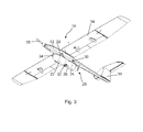
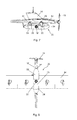
- Fig. 3 shows an overall view of a remotely controller airplane according to one embodiment of the present invention, the airplane being generally indicated by the numeral 10. Additionally, side, bottom, and front views of the airplane 10 are shown in Fig. 4 to 6 .
- the airplane 10 comprises a fuselage 12, a wing 14, a tail 16, and a motor with a propeller 18 installed at the front of the fuselage 12.
- the airplane 10 further comprises an under-fuselage payload container 20 adapted for carrying surveillance equipment.
- the container 10 is of a tubular or cylindrical form with tapered off ends.
- the longitudinal axis of the container 20 is in parallel with the airplane axis.
- the payload container 20 is divided along its longitudinal axis in three parts or modules: a front module 22, a central module 26, and an aft module 24.
- the front module 22 is coupled to the fuselage 12 by two pylons 28 whereas the aft module 24 is also coupled to the fuselage 12 by two pylons 30.
- the front module 22 and the aft module 24 are spaced apart along the fuselage axis with the central module 26 installed between them.
- the central module 26 is rotatably attached to both the front module 22 and the aft module 24, so that it can rotate about the longitudinal axis of the payload container 20.
- the central module 26 has an opening 32 in its external wall for operation of the surveillance equipment, for example, a photo camera installed in the module 26.
- the aircraft 10 is equipped with a navigation camera 34 installed in the front module 22.
- the airplane 10 is equipped with an electric motor and collapsible propeller 18. Additional airplane equipment such as an autopilot system, radio equipment, and control system are installed in the fuselage.
- the placement of the under-fuselage payload container 20 along the fuselage axis is such chosen that the geometrical centre of the central module 26 is under the airplane centre of gravity when the airplane 10 is in the horizontal flight. Such placement of the payload container 20 allows for changing payload weight without changing the airplane balance.
- the payload in the central module 26 is such installed that the module centre of gravity is near its geometrical centre, and then the weight of the central module 26 has a small impact on the overall airplane balance.
- the rotation of the central module 26 is provided by an electric actuator installed in the front module 22 and controlled by a microprocessor.
- the shaft of the actuator has a cogwheel that is coupled with another cogwheel fixed on the central module 26.
- the processor may additionally provide stabilisation function maintaining stable angular position of the central module 26 in relation to the horizon.
- the operation of the airplane is as follows. During the airplane launching the central module 26 is in a landing position, that is the position when the opening 32 is facing away from the downward direction, preferably the opening 32 is facing the fuselage 10.
- the central module 26 is turned in the operation position, that is the position when the installed in the module 26 surveillance equipment is targeting the intended aim.
- the angular position of the central module 26 may be operationally adjusted during the flight, for example to provide camera sweeping to cover a larger area or to compensate for changes in the airplane position, etc.
- Fig. 7 the module 26 is turned so that the camera installed herein is looking sideways
- Fig. 8 the module 26 is turned so that the camera is looking downwards.
- the central module 26 is turned into landing position again.
- the landing position may differ from the one when opening 32 is facing the fuselage 10 to provide an optimal orientation of the surveillance equipment for withstanding the impact with the ground during landing.
- the present invention may be utilized when applied to a remotely controllable airplane adapted for belly-landing and having an under-fuselage container for carrying surveillance equipment.
- the invention provides for improved field of view, improved protection of the equipment.
- the invention also provides for easy replacement of various surveillance equipments.
Landscapes
- Engineering & Computer Science (AREA)
- Mechanical Engineering (AREA)
- Aviation & Aerospace Engineering (AREA)
- Studio Devices (AREA)
Abstract
Description
- The invention relates to remotely controllable airplanes adapted for belly-landing and in particular to such airplanes having an under-fuselage payload.
- Remotely controllable airplanes find wide application for military and civilian purposes when manned flight operations are unacceptably costly and/or dangerous. For example, unmanned aircraft outfitted with remotely operated cameras can perform a wide variety of surveillance missions, including reconnaissance photography, national border patrols, forestry monitoring, agriculture monitoring, road traffic monitoring, etc.
- Small remotely controllable airplanes also called unmanned aerial vehicles or UAVs typically are designed to be launched from a special launcher or by hand and land on dry land. As weight and size are paramount in the design of small unmanned vehicles some of the airplanes do not have dedicated landing gear and are designed for belly-landing on the fuselage or on the under-fuselage container.
- An example of an airplane adapted for belly-landing is a light airplane Aeromapper manufactured by Aeromao company http://www.aeromao.com. This airplane is adapted for belly-landing and comprises an airframe with a wing, tail, fuselage, as well as electrically powered motor with a propeller, and an under-fuselage container with an optional forward looking video camera and a ground-facing camera installed inside. During take-off and landing, the camera is protected by a door in the belly of the aircraft, that opens only while mapping is taking place. In
Fig. 1 an overall view of the Aeromapper is shown, and inFig. 2 the under-fuselage container with the camera door opened and closed. - The problem with the prior art airplane is in that the camera field of view is limited by the door size, the camera protection during landing is not sufficient, various payloads are not suitable for use with the small door opening, therefore the applications of the prior art airplane are limited by the door size.
- It is therefore a broad object of the present invention to improve the prior art airplane. It is further object of the present invention to provide a better protection for the payload during landing.
- It is another object of the present invention to provide a better field of view for the surveillance equipment carried by the airplane.
- It is still another object of the present invention to provide a replaceable payload module to facilitate use of various surveillance equipments.
- In accordance with the present invention, there is provided a remotely controllable airplane adapted for belly-landing, the airplane comprising a fuselage, a wing, a tail, a motor with a propeller, and an under-fuselage payload container adapted for carrying a surveillance equipment, wherein the payload container comprises a front module , an aft module, both coupled to the fuselage and spaced apart along the fuselage axis, and a central module, wherein the central module is rotatably attached to the front module and to the aft module.
- Such configuration of the payload container provides for improved field of view for the surveillance equipment installed in the central module. With a rotatable central module the protection of the camera or other surveillance equipment does not depend on the size of window or opening in the module, therefore the surveillance equipment that require large opening in the container wall may be used.
- Preferably, the front module comprises a navigation video camera, having a dedicated video camera for navigation purpose allows for separate optimisation of the airplane control system and optimisation of various payloads.
- Advantageously, the front module and the aft module are installed on pylons attached to the fuselage. Installing the payload container at some distance from the fuselage reduces or even eliminates the shadowing of the navigation camera by the airplane propeller as well as reduces requirement for the aircraft levelling during landing.
- Preferably, the under-fuselage payload container is such placed that the central module geometrical centre is under the airplane centre of gravity when the airplane is in the horizontal flight. Such placement of the payload container allows for changing payload weight without changing the airplane balance.
- Preferably, the central module has an opening in its lower part, that is the side turned to the ground during the airplane horizontal flight. Depending on the surveillance equipment the opening may be protected by an optically or radio transparent material.
- The central module may be adapted for carrying various surveillance equipments. For example, the airplane may carry such equipment as a video camera, a photo camera, and an infrared camera.
- Preferably, the central module is adapted for rotation in at least within ±90° range. Such range provides for both large enough field of view for the surveillance equipment and for sufficient protection during landing.
- More preferably, the central module is adapted for rotation in at least within ±180° range. Enlarged rotation range not only provides for an enlarged field of view, but also for a better protection of the surveillance equipment during landing as the opening in the central module, which is facing down when surveillance equipment is in operation, is turned to face the fuselage during landing.
- Advantageously, the payload container is having a spindle-shaped form with the container axis parallel to the fuselage axis, and the central module rotatable around the container axis. The streamlined shape of the container reduces air resistance.
- Advantageously, the airplane is adapted for carrying different replaceable central modules with various surveillance equipments. Replacement of a whole central module is easier than replacement of the equipment therein. Whereas replacement of only one central module in comparison to replacement of the whole payload module is more economical as the part of the equipment that is common for various surveillance equipment, e.g. batteries, controllers, rotation actuator, navigation equipment, are installed in the front and aft modules and only the specialised part of the equipment, such as cameras, sensors, etc. are replaceable.
- Preferably, the central module is having a central position and a landing position, wherein the central position is the position when, during the horizontal flight, the surveillance equipment is targeting down, whereas the landing position is the position turned from the central position at at least 45°.
- Preferably, the airplane is adapted for hand launch. The present invention is most advantageously suitable for small airplanes that are launched and retrieved without any additional appliances, i.e. for airplanes that are hand launched by the operator and belly-landed on the dry land, and after replacement or re-charge of batteries are ready for the next flight.
- Other features and advantages of the present invention will be apparent from the following more detailed description of the preferred embodiment, taken in conjunction with the accompanying drawings, which illustrate, by way of example, the principles of the invention. The scope of the invention is not, however, limited to this preferred embodiment.
-
-
Fig. 1 shows a prior art airplane. -
Fig. 2 shows an under-fuselage container of the aeroplane inFig. 1 . -
Fig. 3 is an overall view of an embodiment of the airplane. -
Fig. 4 is a side view of the airplane. -
Fig. 5 is a bottom view. -
Fig. 6 is a front view -
Fig. 7 is an enlarged side view andFig. 8 an enlarged bottom view of the payload container. - The present invention will be further described using the following exemplary embodiments.
-
Fig. 3 . shows an overall view of a remotely controller airplane according to one embodiment of the present invention, the airplane being generally indicated by thenumeral 10. Additionally, side, bottom, and front views of theairplane 10 are shown inFig. 4 to 6 .Theairplane 10 comprises afuselage 12, awing 14, atail 16, and a motor with apropeller 18 installed at the front of thefuselage 12. Theairplane 10 further comprises an under-fuselage payload container 20 adapted for carrying surveillance equipment. Thecontainer 10 is of a tubular or cylindrical form with tapered off ends. The longitudinal axis of thecontainer 20 is in parallel with the airplane axis. Thepayload container 20 is divided along its longitudinal axis in three parts or modules: afront module 22, acentral module 26, and anaft module 24. Thefront module 22 is coupled to thefuselage 12 by twopylons 28 whereas theaft module 24 is also coupled to thefuselage 12 by twopylons 30. Thefront module 22 and theaft module 24 are spaced apart along the fuselage axis with thecentral module 26 installed between them. Thecentral module 26 is rotatably attached to both thefront module 22 and theaft module 24, so that it can rotate about the longitudinal axis of thepayload container 20. Thecentral module 26 has anopening 32 in its external wall for operation of the surveillance equipment, for example, a photo camera installed in themodule 26. Theaircraft 10 is equipped with anavigation camera 34 installed in thefront module 22. - The
airplane 10 is equipped with an electric motor andcollapsible propeller 18. Additional airplane equipment such as an autopilot system, radio equipment, and control system are installed in the fuselage. - The placement of the under-
fuselage payload container 20 along the fuselage axis is such chosen that the geometrical centre of thecentral module 26 is under the airplane centre of gravity when theairplane 10 is in the horizontal flight. Such placement of thepayload container 20 allows for changing payload weight without changing the airplane balance. The payload in thecentral module 26 is such installed that the module centre of gravity is near its geometrical centre, and then the weight of thecentral module 26 has a small impact on the overall airplane balance. - The rotation of the
central module 26 is provided by an electric actuator installed in thefront module 22 and controlled by a microprocessor. The shaft of the actuator has a cogwheel that is coupled with another cogwheel fixed on thecentral module 26. Thus an angular position of thecentral module 26 can be precisely controlled by the processor. The processor may additionally provide stabilisation function maintaining stable angular position of thecentral module 26 in relation to the horizon. - The operation of the airplane is as follows. During the airplane launching the
central module 26 is in a landing position, that is the position when theopening 32 is facing away from the downward direction, preferably theopening 32 is facing thefuselage 10. - During normal flying operation the
central module 26 is turned in the operation position, that is the position when the installed in themodule 26 surveillance equipment is targeting the intended aim. The angular position of thecentral module 26 may be operationally adjusted during the flight, for example to provide camera sweeping to cover a larger area or to compensate for changes in the airplane position, etc. For example, inFig. 7 themodule 26 is turned so that the camera installed herein is looking sideways, whereas inFig. 8 themodule 26 is turned so that the camera is looking downwards. - During landing the
central module 26 is turned into landing position again. Depending on the installed in themodule 26 surveillance equipment the landing position may differ from the one when opening 32 is facing thefuselage 10 to provide an optimal orientation of the surveillance equipment for withstanding the impact with the ground during landing. - The present invention may be utilized when applied to a remotely controllable airplane adapted for belly-landing and having an under-fuselage container for carrying surveillance equipment. The invention provides for improved field of view, improved protection of the equipment. The invention also provides for easy replacement of various surveillance equipments.
-
- 10. airplane
- 12. fuselage
- 14. wing
- 16. tail
- 18. propeller
- 20. payload container
- 22. front module
- 24. aft module
- 26. central module
- 28, 30 pylon
- 32. opening (in the central module)
- 34. navigation camera
Claims (12)
- A remotely controllable airplane (10) adapted for belly-landing, the airplane (10) comprising a fuselage (12), a wing (14), a tail (16), a motor with a propeller (18), and an under-fuselage payload container (20) adapted for carrying a surveillance equipment, characterised in that
the payload container (20) comprises a front module (22), an aft module (24), both coupled to the fuselage (12) and spaced apart along the fuselage axis, and a central module (26), wherein the central module (26) is rotatably attached to the front module (22) and to the aft module (24). - The airplane (10) according to any previous claim wherein the front module (22) comprises a navigation video camera (34).
- The airplane (10) according to any previous claim wherein the front module (22) and the aft module (24) are installed on pylons (28, 30) attached to the fuselage (12).
- The airplane (10) according to any previous claim wherein the under-fuselage payload container (20) is such placed that the central module geometrical centre is under the airplane centre of gravity when the airplane (10) is in the horizontal flight.
- The airplane (10) according to any previous claim wherein the central module (26) has an opening (32) in its lower part.
- The airplane (10) according to any previous claim wherein the central module (26) is adapted for carrying the surveillance equipment selected from the group consisting of a video camera, a photo camera, and a infra-red camera.
- The airplane (10) according to any previous claim wherein the central module (26) is adapted for rotation in at least within ±90° range.
- The airplane (10) according to claim 7 wherein the central module (26) is adapted for rotation in at least within ±180° range.
- The airplane (10) according to any previous claim wherein the payload container is having a spindle-shaped form with the container axis parallel to the fuselage axis.
- The airplane (10) according to any previous claim adapted for carrying different replaceable central modules (26) with various surveillance equipment.
- The airplane (10) according to claim 1 wherein the central module (26) is having a central position and a landing position, wherein the central position is the position when, during the horizontal flight, the surveillance equipment is targeting down, whereas the landing position is the position turned from the central position at at least 45°.
- The airplane (10) according to claim 1 being adapted for hand launch.
Priority Applications (1)
| Application Number | Priority Date | Filing Date | Title |
|---|---|---|---|
| EP13191075.4A EP2868577B1 (en) | 2013-10-31 | 2013-10-31 | Remotely controllable airplane adapted for belly-landing |
Applications Claiming Priority (1)
| Application Number | Priority Date | Filing Date | Title |
|---|---|---|---|
| EP13191075.4A EP2868577B1 (en) | 2013-10-31 | 2013-10-31 | Remotely controllable airplane adapted for belly-landing |
Publications (2)
| Publication Number | Publication Date |
|---|---|
| EP2868577A1 true EP2868577A1 (en) | 2015-05-06 |
| EP2868577B1 EP2868577B1 (en) | 2017-03-01 |
Family
ID=49515247
Family Applications (1)
| Application Number | Title | Priority Date | Filing Date |
|---|---|---|---|
| EP13191075.4A Not-in-force EP2868577B1 (en) | 2013-10-31 | 2013-10-31 | Remotely controllable airplane adapted for belly-landing |
Country Status (1)
| Country | Link |
|---|---|
| EP (1) | EP2868577B1 (en) |
Cited By (5)
| Publication number | Priority date | Publication date | Assignee | Title |
|---|---|---|---|---|
| WO2019097196A1 (en) * | 2017-11-20 | 2019-05-23 | Airbus Defence And Space Sas | Structure of payload module for stratospheric drone |
| WO2023027773A1 (en) * | 2021-08-26 | 2023-03-02 | United Parcel Service Of America, Inc. | Payload container with power supply for unmanned systems |
| US12080907B2 (en) | 2021-08-26 | 2024-09-03 | United Parcel Service Of America, Inc. | Locking mechanism and container for delivering items |
| US12100853B2 (en) | 2021-04-06 | 2024-09-24 | United Parcel Service Of America, Inc. | Pneumatic delivery system and method for use with unmanned vehicle systems |
| US12388147B2 (en) | 2021-08-26 | 2025-08-12 | United Parcel Service Of America, Inc. | Locking mechanism and container for delivering items |
Citations (4)
| Publication number | Priority date | Publication date | Assignee | Title |
|---|---|---|---|---|
| US4746082A (en) * | 1983-07-15 | 1988-05-24 | Flight Refuelling Ltd. | Aircraft and a system including aircraft borne apparatus |
| US6533218B1 (en) * | 1999-10-28 | 2003-03-18 | Raytheon Company | Reconnaissance pod with movable sensor-bay window |
| US20070152099A1 (en) * | 2003-12-12 | 2007-07-05 | Dominique Moreau | Onboard modular optronic system |
| US20100282897A1 (en) * | 2005-08-17 | 2010-11-11 | Chang Industry, Inc. | Unmanned Aerial Surveillance Device |
-
2013
- 2013-10-31 EP EP13191075.4A patent/EP2868577B1/en not_active Not-in-force
Patent Citations (4)
| Publication number | Priority date | Publication date | Assignee | Title |
|---|---|---|---|---|
| US4746082A (en) * | 1983-07-15 | 1988-05-24 | Flight Refuelling Ltd. | Aircraft and a system including aircraft borne apparatus |
| US6533218B1 (en) * | 1999-10-28 | 2003-03-18 | Raytheon Company | Reconnaissance pod with movable sensor-bay window |
| US20070152099A1 (en) * | 2003-12-12 | 2007-07-05 | Dominique Moreau | Onboard modular optronic system |
| US20100282897A1 (en) * | 2005-08-17 | 2010-11-11 | Chang Industry, Inc. | Unmanned Aerial Surveillance Device |
Cited By (10)
| Publication number | Priority date | Publication date | Assignee | Title |
|---|---|---|---|---|
| WO2019097196A1 (en) * | 2017-11-20 | 2019-05-23 | Airbus Defence And Space Sas | Structure of payload module for stratospheric drone |
| AU2018368693B2 (en) * | 2017-11-20 | 2020-08-06 | Airbus Defence And Space Sas | Structure of payload module for stratospheric drone |
| US11352136B2 (en) | 2017-11-20 | 2022-06-07 | Airbus Defence And Space Sas | Structure of payload module for stratospheric drone |
| US12100853B2 (en) | 2021-04-06 | 2024-09-24 | United Parcel Service Of America, Inc. | Pneumatic delivery system and method for use with unmanned vehicle systems |
| US12218370B2 (en) | 2021-04-06 | 2025-02-04 | United Parcel Service Of America, Inc. | Unmanned aerial vehicle (UAV) landing gear system for holding delivery canisters |
| US12451550B2 (en) | 2021-04-06 | 2025-10-21 | United Parcel Service Of America, Inc. | Payload container with power supply for unmanned systems |
| WO2023027773A1 (en) * | 2021-08-26 | 2023-03-02 | United Parcel Service Of America, Inc. | Payload container with power supply for unmanned systems |
| US12080907B2 (en) | 2021-08-26 | 2024-09-03 | United Parcel Service Of America, Inc. | Locking mechanism and container for delivering items |
| US12183940B2 (en) | 2021-08-26 | 2024-12-31 | United Parcel Service Of America, Inc. | Unmanned aerial vehicle (UAV) landing systems |
| US12388147B2 (en) | 2021-08-26 | 2025-08-12 | United Parcel Service Of America, Inc. | Locking mechanism and container for delivering items |
Also Published As
| Publication number | Publication date |
|---|---|
| EP2868577B1 (en) | 2017-03-01 |
Similar Documents
| Publication | Publication Date | Title |
|---|---|---|
| US20230303245A1 (en) | Unmanned supply delivery aircraft | |
| EP2147858B1 (en) | Ducted fan core for use with an unmanned aerial vehicle | |
| US11220170B2 (en) | Reconfigurable battery-operated vehicle system | |
| EP2151379B1 (en) | Modular pods for use with an unmanned aerial vehicle | |
| US20210371081A1 (en) | Air-Launched Unmanned Aerial Vehicle | |
| EP3638585B1 (en) | System and method for launching an unmanned aerial vehicle | |
| US7854410B2 (en) | Powered unmanned aerial vehicle | |
| KR101564380B1 (en) | Unmanned vehicle | |
| US6626398B1 (en) | Unmanned biplane for airborne reconnaissance and surveillance having staggered and gapped wings | |
| US20190233100A1 (en) | Reconfigurable battery-operated vehicle system | |
| CN107161328B (en) | Projectile type disaster rescue and fire extinguishing unmanned aerial vehicle | |
| US9738383B2 (en) | Remote controlled aerial reconnaissance vehicle | |
| GB2455374A (en) | Unmanned aerial vehicle comprising a triangular array of rotors | |
| US20150136897A1 (en) | Aircraft, preferably unmanned | |
| EP2868577B1 (en) | Remotely controllable airplane adapted for belly-landing | |
| US20060284002A1 (en) | Unmanned Urban Aerial Vehicle | |
| US20060102798A1 (en) | Unmanned biplane for airborne reconnaissance and surveillance having staggered and gapped wings | |
| CN105263800A (en) | Vertical take-off and landing unmanned aerial vehicle with twin-yaw control system | |
| EP3787968B1 (en) | Unmanned supply delivery aircraft | |
| WO2008073069A2 (en) | Unmanned aerial vehicle | |
| CA3006445A1 (en) | Rocket propelled drone | |
| Verma et al. | Unmanned Aerial Vehicle for disaster response and relief operations: helping hands from air | |
| Nagarajan et al. | Nano unmanned aerial vehicles-drone or helicopter in military | |
| RU111835U1 (en) | UNMANNED AERIAL VEHICLE | |
| Veerman | Preliminary multi-mission UAS design |
Legal Events
| Date | Code | Title | Description |
|---|---|---|---|
| PUAI | Public reference made under article 153(3) epc to a published international application that has entered the european phase |
Free format text: ORIGINAL CODE: 0009012 |
|
| 17P | Request for examination filed |
Effective date: 20131113 |
|
| AK | Designated contracting states |
Kind code of ref document: A1 Designated state(s): AL AT BE BG CH CY CZ DE DK EE ES FI FR GB GR HR HU IE IS IT LI LT LU LV MC MK MT NL NO PL PT RO RS SE SI SK SM TR |
|
| AX | Request for extension of the european patent |
Extension state: BA ME |
|
| RIC1 | Information provided on ipc code assigned before grant |
Ipc: B64D 47/08 20060101ALI20160811BHEP Ipc: B64C 39/02 20060101AFI20160811BHEP |
|
| GRAP | Despatch of communication of intention to grant a patent |
Free format text: ORIGINAL CODE: EPIDOSNIGR1 |
|
| INTG | Intention to grant announced |
Effective date: 20160921 |
|
| RIN1 | Information on inventor provided before grant (corrected) |
Inventor name: URBAHS, ALEKSANDRS Inventor name: PETROVS, VLADIMIRS Inventor name: URBAHA, MARGARITA Inventor name: BULANOVS, VLADIMIRS Inventor name: JAKOVLEVS, ALEKSANDRS Inventor name: OZOLS, ILMARS |
|
| GRAS | Grant fee paid |
Free format text: ORIGINAL CODE: EPIDOSNIGR3 |
|
| STAA | Information on the status of an ep patent application or granted ep patent |
Free format text: STATUS: GRANT OF PATENT IS INTENDED |
|
| GRAA | (expected) grant |
Free format text: ORIGINAL CODE: 0009210 |
|
| STAA | Information on the status of an ep patent application or granted ep patent |
Free format text: STATUS: THE PATENT HAS BEEN GRANTED |
|
| AK | Designated contracting states |
Kind code of ref document: B1 Designated state(s): AL AT BE BG CH CY CZ DE DK EE ES FI FR GB GR HR HU IE IS IT LI LT LU LV MC MK MT NL NO PL PT RO RS SE SI SK SM TR |
|
| REG | Reference to a national code |
Ref country code: GB Ref legal event code: FG4D |
|
| REG | Reference to a national code |
Ref country code: CH Ref legal event code: EP Ref country code: AT Ref legal event code: REF Ref document number: 870947 Country of ref document: AT Kind code of ref document: T Effective date: 20170315 |
|
| REG | Reference to a national code |
Ref country code: IE Ref legal event code: FG4D |
|
| REG | Reference to a national code |
Ref country code: DE Ref legal event code: R096 Ref document number: 602013017898 Country of ref document: DE |
|
| REG | Reference to a national code |
Ref country code: NL Ref legal event code: MP Effective date: 20170301 |
|
| REG | Reference to a national code |
Ref country code: LT Ref legal event code: MG4D |
|
| REG | Reference to a national code |
Ref country code: AT Ref legal event code: MK05 Ref document number: 870947 Country of ref document: AT Kind code of ref document: T Effective date: 20170301 |
|
| PG25 | Lapsed in a contracting state [announced via postgrant information from national office to epo] |
Ref country code: HR Free format text: LAPSE BECAUSE OF FAILURE TO SUBMIT A TRANSLATION OF THE DESCRIPTION OR TO PAY THE FEE WITHIN THE PRESCRIBED TIME-LIMIT Effective date: 20170301 Ref country code: GR Free format text: LAPSE BECAUSE OF FAILURE TO SUBMIT A TRANSLATION OF THE DESCRIPTION OR TO PAY THE FEE WITHIN THE PRESCRIBED TIME-LIMIT Effective date: 20170602 Ref country code: LT Free format text: LAPSE BECAUSE OF FAILURE TO SUBMIT A TRANSLATION OF THE DESCRIPTION OR TO PAY THE FEE WITHIN THE PRESCRIBED TIME-LIMIT Effective date: 20170301 Ref country code: FI Free format text: LAPSE BECAUSE OF FAILURE TO SUBMIT A TRANSLATION OF THE DESCRIPTION OR TO PAY THE FEE WITHIN THE PRESCRIBED TIME-LIMIT Effective date: 20170301 Ref country code: NO Free format text: LAPSE BECAUSE OF FAILURE TO SUBMIT A TRANSLATION OF THE DESCRIPTION OR TO PAY THE FEE WITHIN THE PRESCRIBED TIME-LIMIT Effective date: 20170601 |
|
| PG25 | Lapsed in a contracting state [announced via postgrant information from national office to epo] |
Ref country code: LV Free format text: LAPSE BECAUSE OF FAILURE TO SUBMIT A TRANSLATION OF THE DESCRIPTION OR TO PAY THE FEE WITHIN THE PRESCRIBED TIME-LIMIT Effective date: 20170301 Ref country code: ES Free format text: LAPSE BECAUSE OF FAILURE TO SUBMIT A TRANSLATION OF THE DESCRIPTION OR TO PAY THE FEE WITHIN THE PRESCRIBED TIME-LIMIT Effective date: 20170301 Ref country code: RS Free format text: LAPSE BECAUSE OF FAILURE TO SUBMIT A TRANSLATION OF THE DESCRIPTION OR TO PAY THE FEE WITHIN THE PRESCRIBED TIME-LIMIT Effective date: 20170301 Ref country code: SE Free format text: LAPSE BECAUSE OF FAILURE TO SUBMIT A TRANSLATION OF THE DESCRIPTION OR TO PAY THE FEE WITHIN THE PRESCRIBED TIME-LIMIT Effective date: 20170301 Ref country code: AT Free format text: LAPSE BECAUSE OF FAILURE TO SUBMIT A TRANSLATION OF THE DESCRIPTION OR TO PAY THE FEE WITHIN THE PRESCRIBED TIME-LIMIT Effective date: 20170301 Ref country code: BG Free format text: LAPSE BECAUSE OF FAILURE TO SUBMIT A TRANSLATION OF THE DESCRIPTION OR TO PAY THE FEE WITHIN THE PRESCRIBED TIME-LIMIT Effective date: 20170601 |
|
| PG25 | Lapsed in a contracting state [announced via postgrant information from national office to epo] |
Ref country code: NL Free format text: LAPSE BECAUSE OF FAILURE TO SUBMIT A TRANSLATION OF THE DESCRIPTION OR TO PAY THE FEE WITHIN THE PRESCRIBED TIME-LIMIT Effective date: 20170301 |
|
| PG25 | Lapsed in a contracting state [announced via postgrant information from national office to epo] |
Ref country code: IT Free format text: LAPSE BECAUSE OF FAILURE TO SUBMIT A TRANSLATION OF THE DESCRIPTION OR TO PAY THE FEE WITHIN THE PRESCRIBED TIME-LIMIT Effective date: 20170301 Ref country code: EE Free format text: LAPSE BECAUSE OF FAILURE TO SUBMIT A TRANSLATION OF THE DESCRIPTION OR TO PAY THE FEE WITHIN THE PRESCRIBED TIME-LIMIT Effective date: 20170301 Ref country code: RO Free format text: LAPSE BECAUSE OF FAILURE TO SUBMIT A TRANSLATION OF THE DESCRIPTION OR TO PAY THE FEE WITHIN THE PRESCRIBED TIME-LIMIT Effective date: 20170301 Ref country code: SK Free format text: LAPSE BECAUSE OF FAILURE TO SUBMIT A TRANSLATION OF THE DESCRIPTION OR TO PAY THE FEE WITHIN THE PRESCRIBED TIME-LIMIT Effective date: 20170301 Ref country code: CZ Free format text: LAPSE BECAUSE OF FAILURE TO SUBMIT A TRANSLATION OF THE DESCRIPTION OR TO PAY THE FEE WITHIN THE PRESCRIBED TIME-LIMIT Effective date: 20170301 |
|
| PG25 | Lapsed in a contracting state [announced via postgrant information from national office to epo] |
Ref country code: PL Free format text: LAPSE BECAUSE OF FAILURE TO SUBMIT A TRANSLATION OF THE DESCRIPTION OR TO PAY THE FEE WITHIN THE PRESCRIBED TIME-LIMIT Effective date: 20170301 Ref country code: SM Free format text: LAPSE BECAUSE OF FAILURE TO SUBMIT A TRANSLATION OF THE DESCRIPTION OR TO PAY THE FEE WITHIN THE PRESCRIBED TIME-LIMIT Effective date: 20170301 Ref country code: PT Free format text: LAPSE BECAUSE OF FAILURE TO SUBMIT A TRANSLATION OF THE DESCRIPTION OR TO PAY THE FEE WITHIN THE PRESCRIBED TIME-LIMIT Effective date: 20170703 Ref country code: IS Free format text: LAPSE BECAUSE OF FAILURE TO SUBMIT A TRANSLATION OF THE DESCRIPTION OR TO PAY THE FEE WITHIN THE PRESCRIBED TIME-LIMIT Effective date: 20170701 |
|
| REG | Reference to a national code |
Ref country code: DE Ref legal event code: R097 Ref document number: 602013017898 Country of ref document: DE |
|
| PLBE | No opposition filed within time limit |
Free format text: ORIGINAL CODE: 0009261 |
|
| STAA | Information on the status of an ep patent application or granted ep patent |
Free format text: STATUS: NO OPPOSITION FILED WITHIN TIME LIMIT |
|
| PG25 | Lapsed in a contracting state [announced via postgrant information from national office to epo] |
Ref country code: DK Free format text: LAPSE BECAUSE OF FAILURE TO SUBMIT A TRANSLATION OF THE DESCRIPTION OR TO PAY THE FEE WITHIN THE PRESCRIBED TIME-LIMIT Effective date: 20170301 |
|
| 26N | No opposition filed |
Effective date: 20171204 |
|
| PG25 | Lapsed in a contracting state [announced via postgrant information from national office to epo] |
Ref country code: SI Free format text: LAPSE BECAUSE OF FAILURE TO SUBMIT A TRANSLATION OF THE DESCRIPTION OR TO PAY THE FEE WITHIN THE PRESCRIBED TIME-LIMIT Effective date: 20170301 |
|
| PGFP | Annual fee paid to national office [announced via postgrant information from national office to epo] |
Ref country code: GB Payment date: 20171228 Year of fee payment: 5 |
|
| PG25 | Lapsed in a contracting state [announced via postgrant information from national office to epo] |
Ref country code: MC Free format text: LAPSE BECAUSE OF FAILURE TO SUBMIT A TRANSLATION OF THE DESCRIPTION OR TO PAY THE FEE WITHIN THE PRESCRIBED TIME-LIMIT Effective date: 20170301 |
|
| REG | Reference to a national code |
Ref country code: CH Ref legal event code: PL |
|
| REG | Reference to a national code |
Ref country code: IE Ref legal event code: MM4A |
|
| REG | Reference to a national code |
Ref country code: FR Ref legal event code: ST Effective date: 20180629 |
|
| PG25 | Lapsed in a contracting state [announced via postgrant information from national office to epo] |
Ref country code: CH Free format text: LAPSE BECAUSE OF NON-PAYMENT OF DUE FEES Effective date: 20171031 Ref country code: LU Free format text: LAPSE BECAUSE OF NON-PAYMENT OF DUE FEES Effective date: 20171031 Ref country code: LI Free format text: LAPSE BECAUSE OF NON-PAYMENT OF DUE FEES Effective date: 20171031 |
|
| PGFP | Annual fee paid to national office [announced via postgrant information from national office to epo] |
Ref country code: DE Payment date: 20180409 Year of fee payment: 5 |
|
| REG | Reference to a national code |
Ref country code: BE Ref legal event code: MM Effective date: 20171031 |
|
| PG25 | Lapsed in a contracting state [announced via postgrant information from national office to epo] |
Ref country code: FR Free format text: LAPSE BECAUSE OF NON-PAYMENT OF DUE FEES Effective date: 20171031 Ref country code: BE Free format text: LAPSE BECAUSE OF NON-PAYMENT OF DUE FEES Effective date: 20171031 |
|
| PG25 | Lapsed in a contracting state [announced via postgrant information from national office to epo] |
Ref country code: MT Free format text: LAPSE BECAUSE OF NON-PAYMENT OF DUE FEES Effective date: 20171031 |
|
| PG25 | Lapsed in a contracting state [announced via postgrant information from national office to epo] |
Ref country code: IE Free format text: LAPSE BECAUSE OF NON-PAYMENT OF DUE FEES Effective date: 20171031 |
|
| REG | Reference to a national code |
Ref country code: DE Ref legal event code: R119 Ref document number: 602013017898 Country of ref document: DE |
|
| GBPC | Gb: european patent ceased through non-payment of renewal fee |
Effective date: 20181031 |
|
| PG25 | Lapsed in a contracting state [announced via postgrant information from national office to epo] |
Ref country code: HU Free format text: LAPSE BECAUSE OF FAILURE TO SUBMIT A TRANSLATION OF THE DESCRIPTION OR TO PAY THE FEE WITHIN THE PRESCRIBED TIME-LIMIT; INVALID AB INITIO Effective date: 20131031 |
|
| PG25 | Lapsed in a contracting state [announced via postgrant information from national office to epo] |
Ref country code: DE Free format text: LAPSE BECAUSE OF NON-PAYMENT OF DUE FEES Effective date: 20190501 |
|
| PG25 | Lapsed in a contracting state [announced via postgrant information from national office to epo] |
Ref country code: GB Free format text: LAPSE BECAUSE OF NON-PAYMENT OF DUE FEES Effective date: 20181031 Ref country code: CY Free format text: LAPSE BECAUSE OF FAILURE TO SUBMIT A TRANSLATION OF THE DESCRIPTION OR TO PAY THE FEE WITHIN THE PRESCRIBED TIME-LIMIT Effective date: 20170301 |
|
| PG25 | Lapsed in a contracting state [announced via postgrant information from national office to epo] |
Ref country code: MK Free format text: LAPSE BECAUSE OF FAILURE TO SUBMIT A TRANSLATION OF THE DESCRIPTION OR TO PAY THE FEE WITHIN THE PRESCRIBED TIME-LIMIT Effective date: 20170301 |
|
| PG25 | Lapsed in a contracting state [announced via postgrant information from national office to epo] |
Ref country code: TR Free format text: LAPSE BECAUSE OF FAILURE TO SUBMIT A TRANSLATION OF THE DESCRIPTION OR TO PAY THE FEE WITHIN THE PRESCRIBED TIME-LIMIT Effective date: 20170301 |
|
| PG25 | Lapsed in a contracting state [announced via postgrant information from national office to epo] |
Ref country code: AL Free format text: LAPSE BECAUSE OF FAILURE TO SUBMIT A TRANSLATION OF THE DESCRIPTION OR TO PAY THE FEE WITHIN THE PRESCRIBED TIME-LIMIT Effective date: 20170301 |