EP2869401B1 - Tige de mise à la terre pour appendice sacrificielle - Google Patents
Tige de mise à la terre pour appendice sacrificielle Download PDFInfo
- Publication number
- EP2869401B1 EP2869401B1 EP14190650.3A EP14190650A EP2869401B1 EP 2869401 B1 EP2869401 B1 EP 2869401B1 EP 14190650 A EP14190650 A EP 14190650A EP 2869401 B1 EP2869401 B1 EP 2869401B1
- Authority
- EP
- European Patent Office
- Prior art keywords
- sacrificial
- yoke
- outwardly extending
- electrical connector
- cable
- Prior art date
- Legal status (The legal status is an assumption and is not a legal conclusion. Google has not performed a legal analysis and makes no representation as to the accuracy of the status listed.)
- Active
Links
Images


Classifications
-
- H—ELECTRICITY
- H01—ELECTRIC ELEMENTS
- H01R—ELECTRICALLY-CONDUCTIVE CONNECTIONS; STRUCTURAL ASSOCIATIONS OF A PLURALITY OF MUTUALLY-INSULATED ELECTRICAL CONNECTING ELEMENTS; COUPLING DEVICES; CURRENT COLLECTORS
- H01R4/00—Electrically-conductive connections between two or more conductive members in direct contact, i.e. touching one another; Means for effecting or maintaining such contact; Electrically-conductive connections having two or more spaced connecting locations for conductors and using contact members penetrating insulation
- H01R4/28—Clamped connections, spring connections
-
- H—ELECTRICITY
- H01—ELECTRIC ELEMENTS
- H01R—ELECTRICALLY-CONDUCTIVE CONNECTIONS; STRUCTURAL ASSOCIATIONS OF A PLURALITY OF MUTUALLY-INSULATED ELECTRICAL CONNECTING ELEMENTS; COUPLING DEVICES; CURRENT COLLECTORS
- H01R4/00—Electrically-conductive connections between two or more conductive members in direct contact, i.e. touching one another; Means for effecting or maintaining such contact; Electrically-conductive connections having two or more spaced connecting locations for conductors and using contact members penetrating insulation
- H01R4/58—Electrically-conductive connections between two or more conductive members in direct contact, i.e. touching one another; Means for effecting or maintaining such contact; Electrically-conductive connections having two or more spaced connecting locations for conductors and using contact members penetrating insulation characterised by the form or material of the contacting members
- H01R4/64—Connections between or with conductive parts having primarily a non-electric function, e.g. frame, casing, rail
-
- H—ELECTRICITY
- H01—ELECTRIC ELEMENTS
- H01R—ELECTRICALLY-CONDUCTIVE CONNECTIONS; STRUCTURAL ASSOCIATIONS OF A PLURALITY OF MUTUALLY-INSULATED ELECTRICAL CONNECTING ELEMENTS; COUPLING DEVICES; CURRENT COLLECTORS
- H01R13/00—Details of coupling devices of the kinds covered by groups H01R12/70 or H01R24/00 - H01R33/00
- H01R13/40—Securing contact members in or to a base or case; Insulating of contact members
- H01R13/42—Securing in a demountable manner
-
- H—ELECTRICITY
- H01—ELECTRIC ELEMENTS
- H01R—ELECTRICALLY-CONDUCTIVE CONNECTIONS; STRUCTURAL ASSOCIATIONS OF A PLURALITY OF MUTUALLY-INSULATED ELECTRICAL CONNECTING ELEMENTS; COUPLING DEVICES; CURRENT COLLECTORS
- H01R13/00—Details of coupling devices of the kinds covered by groups H01R12/70 or H01R24/00 - H01R33/00
- H01R13/46—Bases; Cases
- H01R13/53—Bases or cases for heavy duty; Bases or cases for high voltage with means for preventing corona or arcing
-
- H—ELECTRICITY
- H01—ELECTRIC ELEMENTS
- H01R—ELECTRICALLY-CONDUCTIVE CONNECTIONS; STRUCTURAL ASSOCIATIONS OF A PLURALITY OF MUTUALLY-INSULATED ELECTRICAL CONNECTING ELEMENTS; COUPLING DEVICES; CURRENT COLLECTORS
- H01R4/00—Electrically-conductive connections between two or more conductive members in direct contact, i.e. touching one another; Means for effecting or maintaining such contact; Electrically-conductive connections having two or more spaced connecting locations for conductors and using contact members penetrating insulation
- H01R4/10—Electrically-conductive connections between two or more conductive members in direct contact, i.e. touching one another; Means for effecting or maintaining such contact; Electrically-conductive connections having two or more spaced connecting locations for conductors and using contact members penetrating insulation effected solely by twisting, wrapping, bending, crimping, or other permanent deformation
- H01R4/18—Electrically-conductive connections between two or more conductive members in direct contact, i.e. touching one another; Means for effecting or maintaining such contact; Electrically-conductive connections having two or more spaced connecting locations for conductors and using contact members penetrating insulation effected solely by twisting, wrapping, bending, crimping, or other permanent deformation by crimping
-
- H—ELECTRICITY
- H01—ELECTRIC ELEMENTS
- H01R—ELECTRICALLY-CONDUCTIVE CONNECTIONS; STRUCTURAL ASSOCIATIONS OF A PLURALITY OF MUTUALLY-INSULATED ELECTRICAL CONNECTING ELEMENTS; COUPLING DEVICES; CURRENT COLLECTORS
- H01R43/00—Apparatus or processes specially adapted for manufacturing, assembling, maintaining, or repairing of line connectors or current collectors or for joining electric conductors
- H01R43/002—Maintenance of line connectors, e.g. cleaning
-
- H—ELECTRICITY
- H02—GENERATION; CONVERSION OR DISTRIBUTION OF ELECTRIC POWER
- H02G—INSTALLATION OF ELECTRIC CABLES OR LINES, OR OF COMBINED OPTICAL AND ELECTRIC CABLES OR LINES
- H02G15/00—Cable fittings
- H02G15/08—Cable junctions
- H02G15/10—Cable junctions protected by boxes, e.g. by distribution, connection or junction boxes
- H02G15/103—Cable junctions protected by boxes, e.g. by distribution, connection or junction boxes with devices for relieving electrical stress
-
- H—ELECTRICITY
- H02—GENERATION; CONVERSION OR DISTRIBUTION OF ELECTRIC POWER
- H02G—INSTALLATION OF ELECTRIC CABLES OR LINES, OR OF COMBINED OPTICAL AND ELECTRIC CABLES OR LINES
- H02G15/00—Cable fittings
- H02G15/02—Cable terminations
- H02G15/06—Cable terminating boxes, frames or other structures
- H02G15/064—Cable terminating boxes, frames or other structures with devices for relieving electrical stress
Definitions
- the present invention relates to a grounding rod for a sacrificial appendage of an electrical cable connector, such as a splicing connector for joining two or more electrical cables. More particularly, aspects described herein relate to an electrical cable connector that includes a feature for enabling personnel to ensure that the connector is de-energized and which can be removed and replaced with a ground rod to which a grounding device can be connected to ground the system.
- one leg of the spliced connection must first be disconnected, and then a grounding device, such as a ground clamp, can be attached in order to connect the splice to system ground. Because this requires partially disassembling the splice, it is a time consuming practice.
- US 2011/0217876 A1 discloses an electrical connector assembly according to the preamble of claim 1.
- US 3,883,208 discloses a visible break tee-connector for connecting a primary cable to a bushing. The primary cable is connected to a cable connecting element which is positioned within a resilient dielectric housing. The housing has an open end that can be closed by means of a cap. The connector is prepared for disconnection by removing the cap and grounding the contact assembly by means of a grounded disconnect tool.
- US 7,901,243 B1 discloses a protected disconnectable joint assembly including a three-way yoke.
- a grounding rod for a sacrificial appendage of medium and high voltage electrical cable connectors, such as "I”, "Y” and “H” splicing connectors is disclosed.
- the sacrificial appendage is cut to confirm that the system has been de-energized, and then a cap of the appendage is removed and replaced with a grounding rod to which a grounding device is attached so that the splicing connector and any attached cables can be connected to system ground.
- FIG. 1 Shown in FIG. 1 is a cross-sectional diagram illustrating a power cable splicing connector 100 configured in a manner consistent with the implementations described herein.
- power cable splicing connector 100 may include a four-way yoke 102 for enabling connection of power cables 104-1, 104-2, 104-3 and 104-4 (collectively "power cables 104," and individually “power cable 104-x").
- power cable 104-1 may be a supply cable and cables 104-2 to 104-4 may be load cables.
- Other types of power cable splicing connectors may be configured in accordance with implementations described herein, such as three-way yoke connectors, two-way yoke connectors, etc.
- yoke 102 of power cable splicing connector 100 may include a central conductor 106 and a number of splice openings 108-1 to 108-4 (collectively “splice openings 108," and individually “splice opening 108-x").
- Central conductor 106 may be formed of a suitably conductive material, such as copper, aluminum or other conductive alloy. Further, as shown in FIG. 1 , central conductor 106 may include outwardly extending portions 110-1 to 110-4 (collectively “outwardly extending portions 110,” and individually “outwardly extending portion 110- x ”) that project from respective splice openings 108-x.
- central conductor 106 may connect each of power cables 104-x to each other power cable 104-x, such that voltage applied to one cable is transferred to each other cable.
- Outwardly extending portions 110 may be configured to receive connector portions of power cables 104.
- each extending portion 110-x may include a spade portion 111 having a threaded bore 112 therein for receiving a connector bolt 114.
- outwardly extending portion 110-1 extends oppositely from outwardly extending portion 110-2 and outwardly extending portion 110-3 extends oppositely from outwardly extending portion 110-4.
- outwardly extending portions 110-1 and 110-2 may be oriented parallel to outwardly extending portions 110-3 and 110-4, respectively.
- Such a configuration may provide for compact splicing or splitting of a power supply cable (e.g., cable 104-1) to multiple load cables (e.g., cables 104-2 to 104-4).
- each splice opening 108-x includes a cable receptacle interface that includes a substantially cylindrical flange or cuff portion configured to frictionally engage a cable receptacle 116-x (individually, cable receptacle 116-x, or collectively, cable receptacles 116).
- a cable receptacle 116-x (individually, cable receptacle 116-x, or collectively, cable receptacles 116).
- an inside diameter of a forward end of cable receptacle 1166x may be sized to frictionally engage the cuff portion of splice opening 108-x.
- Each cable receptacle 116-x may be substantially cylindrical and may be configured to surround and protect an interface between power cables 104 and extending portions 110.
- Yoke 102 may include an outer shield 120 formed from, for example, a peroxide-cured synthetic rubber, commonly referred to as EPDM (ethylene-propylene-diene monomer). Within shield 120, yoke 102 may included an insulative inner housing 122, typically molded from an insulative rubber or epoxy material. Central conductor 106 may be enclosed within insulative inner housing 122.
- EPDM ethylene-propylene-diene monomer
- each cable receptacle 116-x may include an EPDM outer shield 124 and an insulative inner housing 126, typically molded from an insulative rubber or epoxy material. Cable receptacle 116-x further includes a conductive or semi-conductive insert 128 having a bore there through. Upon assembly, cable receptacle 116-x surrounds the interface between power cable 104-x and outwardly extending portion 110- x . In one implementation, a forward end of insert 128 may be configured to frictionally engage outwardly extending portion 110-x of central conductor 106 upon assembly of splicing connector 100, thereby ensuring the electrical integrity of splicing connector 100.
- each power cable 104-x may be prepared by connecting power cable 104-x to a crimp connector 130.
- Crimp connector 130 may include a substantially cylindrical assembly configured to receive a cable conductor 132 of power cable 104-x therein.
- a portion of crimp connector 130 may be physically deformed (e.g., crimped) to fasten crimp connector 130 to cable conductor 132.
- Crimp connector portion 130 may include a forward spade portion 134 configured to be securely fastened to the spade portion 111 of outwardly extending portion 110-x of central conductor 106.
- forward spade portion 134 may include a bore (not shown) configured to align with bore 112 in spade portion 111.
- Connector bolt 114 may be inserted through the bore and into threaded bore 112 during assembly of splice connector 100.
- each of the prepared power cables 104 may further include an adapter 138 disposed rearwardly relative to crimp connector 130.
- Adapter 138 may be affixed to power cable 104-x and may provide a frictional engagement with a rearward portion of cable receptacle 116-x.
- adapter 138 may be formed of an insulative material, such as rubber or epoxy.
- yoke 102 may include a sacrificial appendage 148 projecting there-from.
- sacrificial appendage 148 may project substantially perpendicularly from outwardly extending portions 110, so as to be relatively free of encumbrances.
- a worker may cut through sacrificial appendage 148 (e.g., with a hydraulic cable cutter, or similar tool) to ensure that the electrical system that the splicing connector 100 is connected to has been properly de-energized and is, therefore, safe to work on.
- sacrificial appendage connection portion 152 may be integrally formed with inner housing 122 and may include a contact 154 provided therein. Contact 154 may extend into a corresponding portion of central conductor 106, such as via a threaded bore provided in central conductor 106. Contact 154 may include a female thread 155 at an outer end thereof for receiving a sacrificial cap 156 and for receiving a ground rod 151 for grounding the system, to be described below.
- sacrificial cap 156 may include an EPDM outer shield 158 and an insulative inner housing 160, typically molded from an insulative rubber or epoxy material. Sacrificial cap 156 may further include a sacrificial conductor 162 received within a rearward portion of inner housing 160. Furthermore, a forward portion of sacrificial cap 156 may include a cavity 164 therein, shown in FIG. 2 , for engaging a projecting portion of sacrificial appendage connection portion 152.
- a forward portion of outer shield 158 and inner housing 160 may be configured to surround and protect an interface between sacrificial appendage connection portion 152 and sacrificial conductor 162.
- a forward end of outer shield 158 and inner housing 160 may be configured to frictionally engage a stepped or notched outer configuration of sacrificial appendage connection portion 152 upon assembly of splicing connector 100, thereby ensuring the electrical integrity of splicing connector 100.
- sacrificial conductor 162 may include a conductive threaded male protrusion 166 extending axially there-from.
- the projecting portion of contact 154 of sacrificial appendage connection portion 152 may include threaded female cavity 155.
- Male protrusion 166 may correspond to threaded female portion 155 in contact 154 to couple contact 154 to sacrificial conductor 162, thereby conductively connecting sacrificial conductor 162 to central conductor 106 of yoke 102.
- the male/female relationship may be reversed.
- a cut-through region 168 may be provided in an outer portion of sacrificial cap 156 in a region overlying at least a portion of sacrificial conductor 162, as shown in FIG. 2 .
- indicia 169 relating to cut-through region 168 may be provided on a surface of outer shield 158, shown in FIG. 3 , for indicating that a user is to cut through sacrificial cap 156 at cut-through region 168.
- a worker may cut through sacrificial cap 156 at cut-through region 168 (e.g., with a grounded hydraulic cable cutter, or similar tool) to ensure that the electrical system that splicing connector 100 is connected to has been properly de-energized, and is, therefore, safe to work on.
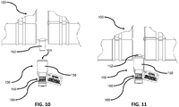
- cut-through sacrificial cap 156 may be discarded and a new or replacement sacrificial cap 156 may be installed, as shown in FIGS. 10 and 11 .
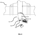
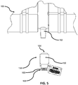
- the sacrificial appendage connection portion 152 and its corresponding threaded female cavity 155 can accept a ground rod 151 (once the cut-through sacrificial cap 156 has been removed, as shown in FIG.
- the ground rod 151 may or may not have an EPDM molded cap 149 on its end which connects to sacrificial appendage connection portion 152. If a ground rod 151 is used which has the molded cap 149, then the cap 149 covers the interface between the ground rod 151 and the sacrificial appendage connection portion 152.
- the ground rod 151 is comprised of a threaded male protrusion 153 on its end which connects to sacrificial appendage connection portion 152, which thereby corresponds to the threaded female cavity 155 as described above. Because the threaded female cavity 155 is part of the contact 154 which extends into a corresponding portion of central conductor 106, as shown in FIG. 1 , this allows for the ground rod 151 to be mechanically and conductively coupled to the splicing connector 100 when the ground rod is attached to the connection portion 152.
- ground rod 151 Once the ground rod 151 is securely attached to the sacrificial appendage connection portion 152, a worker may connect a grounding device, such as a grounding clamp, to ground rod 151 to ensure that the splicing connector 100 is properly connected to system ground so that it may be safely serviced.
- a grounding device such as a grounding clamp
- FIGS. 8 and 9 are two types of grounding devices which can be attached to ground rod 151 in order to connect splicing connector 100 and any attached cables to system ground.
- FIG. 8 shows the ground rod 151 without the molded cap 149
- FIG. 9 shows the ground rod with the molded cap 149, as previously described.
- Both figures show a bar type grounding clamp 172 and a ball type grounding clamp 170.
- the ball type grounding clamp 170 attaches to a ball end 157 of ground rod 151.
- the bar type grounding clamp 172 attaches to a middle portion 159 of ground rod 151. Either type of grounding clamp 170 or 172 may be used to achieve the purpose of connecting the splicing connector 100 to system ground.
- grounding clamp 170 or 172 is connected to system ground in order to ground splicing connector 100 and any attached cables once the ground clamp 170 or 172 is attached to ground rod 151.
- ground clamps 170 and 172 are the only two grounding devices shown, it is understood that other types of grounding devices may be available to attach to ground rod 151 in order to achieve the purpose of connecting splicing connector 100 to system ground.
- ground clamp 170 or 172 may then be removed from the ground rod 151.
- the ground rod 151 may then be removed from the sacrificial appendage connection portion 152 by unscrewing the threaded male protrusion 153 from the threaded female cavity 155, and a new and intact sacrificial cap 156 may be installed on sacrificial appendage connection portion 152, connecting to sacrificial appendage connection portion 152 as described above.
- the placement of a new, intact sacrificial cap 156 is shown in FIGS. 10 and 11 . Once the new, intact sacrificial cap 156 is securely installed, the system may be safely energized once again.
- the above described invention allows for a quick and convenient manner of detecting whether or not a system has been de-energized and a way to safely and conveniently ground that same system.
- FIG. 12 shown in FIG. 12 is a flowchart showing a sequence of events to properly use the sacrificial appendage 148 and ground rod 151 of the splicing connector 100 described above.
- the flowchart illustrates the following steps: providing the splicing connector 100 which is comprised of a sacrificial appendage connection portion 152 for a sacrificial appendage 148 that is conductively connected to the splicing connector 100, confirming that the splicing connector 100 and any equipment conductively coupled to the connector 100 is de-energized by cutting through the cut-through region 168 of the sacrificial appendage 148, removing the cut-through sacrificial appendage 148, replacing the cut-through sacrificial appendage 148 with a ground rod 151 which is releasably retained within the sacrificial appendage connection portion 152, connecting a grounding clamp 170 or 172 which is connected to system ground to the ground rod 151, performing
Landscapes
- Engineering & Computer Science (AREA)
- Manufacturing & Machinery (AREA)
- Cable Accessories (AREA)
- Details Of Connecting Devices For Male And Female Coupling (AREA)
- Manufacturing Of Electrical Connectors (AREA)
Claims (11)
- Connecteur électrique (100), comprenant :une fourche (102) composée d'un boîtier externe (120) et d'un conducteur central (106) à l'intérieur du boîtier externe (120), dans lequel la fourche (102) peut être raccordée à au moins un câble (104) ;un appendice sacrificiel (148) retenu de manière détachable à l'intérieur de la fourche (102) et en contact conducteur avec le conducteur central de fourche (106), l'appendice sacrificiel (148) étant configuré pour être sectionné afin de confirmer que le connecteur électrique (100) est désactivé ;dans lequel, après le sectionnement de l'appendice sacrificiel (148), l'appendice sacrificiel (148) peut être retiré de la fourche (102), caractérisé en ce que :après le retrait de l'appendice sacrificiel (148), une tige de mise à la terre retenue de manière détachable (151) est montée sur la fourche (102) à la place de l'appendice sacrificiel (148) et en contact conducteur avec le conducteur central (106), dans lequel la tige de mise à la terre (151) est configurée pour pouvoir être raccordée à la masse du système pour relier à la terre le connecteur électrique (100) pour permettre à au moins un câble (104), ou à un circuit qui peut être raccordé à ce dernier, d'être mis en service ;dans lequel, après que la mise en service est terminée, la tige de mise à la terre (151) est retirée de la fourche (102) et remplacée par un nouvel appendice sacrificiel (148) intact qui est retenu de manière détachable à l'intérieur de la fourche (102) et qui est raccordé mécaniquement et de manière conductrice au conducteur central (106) de telle sorte que le connecteur électrique puisse être à nouveau alimenté.
- Connecteur électrique (100) selon la revendication 1, dans lequel la fourche (102) comprend une fourche à deux branches, une fourche à trois branches ou une fourche à quatre branches.
- Connecteur électrique (100) selon la revendication 1 ou la revendication 2, dans lequel la tige de mise à la terre (151) comprend en outre un embout sphérique arrondi (157) sur une partie s'étendant vers l'extérieur de la tige de mise à la terre (151) qui s'étend depuis le boîtier externe (120) de la fourche (102) pour une fixation à une bride de mise à la terre de type sphérique (170) .
- Connecteur électrique (100) selon l'une quelconque des revendications précédentes, dans lequel la tige de mise à la terre (151) comprend en outre une partie allongée intermédiaire (159) de la tige de mise à la terre (151) pour une fixation à une bride de mise à la terre de type barre (172).
- Connecteur électrique (100) selon l'une quelconque des revendications précédentes, dans lequel le conducteur central (106) comprend au moins trois parties s'étendant vers l'extérieur (110) qui sont composées d'une première partie s'étendant vers l'extérieur et d'une deuxième partie s'étendant vers l'extérieur du conducteur central (106) qui peuvent être couplées de manière fonctionnelle à des premier et second câbles d'alimentation (104), respectivement, et d'une troisième partie s'étendant vers l'extérieur du conducteur central qui est composée de l'appendice sacrificiel (148).
- Connecteur électrique (100) selon la revendication 5, dans lequel l'appendice sacrificiel (148) comprend un capuchon sacrificiel (156) et dans lequel la fourche (102) est configurée pour retenir de manière détachable le capuchon sacrificiel (156) en contact conducteur avec la troisième partie d'étendant vers l'extérieur.
- Connecteur électrique (100) selon la revendication 6, dans lequel la troisième partie d'étendant vers l'extérieur comprend en outre une interface sacrificielle (154) couplée de manière conductrice à la troisième partie d'étendant vers l'extérieur et dans lequel l'interface sacrificielle (154) est configurée pour recevoir de manière détachable le capuchon sacrificiel (156) sur cette dernière.
- Connecteur électrique (100) selon la revendication 7, dans lequel le capuchon sacrificiel (156) comprend en outre un boîtier interne isolant (160) et un conducteur sacrificiel (162) s'étendant axialement dans le boîtier (120) et dans lequel le boîtier (120) comprend une région découpée recouvrant le conducteur sacrificiel (162) et dans lequel le conducteur sacrificiel (162), et le capuchon sacrificiel (156) à l'intérieur duquel il est logé, est configuré pour une fixation libérable à l'interface sacrificielle (154).
- Connecteur électrique (100) selon l'une quelconque des revendications 5 à 8, comprenant en outre un premier logement de câble (116-1) pour fournir une interface entre la première partie s'étendant vers l'extérieur (110-1) et le premier câble d'alimentation (104-1) et un second logement de câble (116-2) pour fournir une interface entre la deuxième partie s'étendant vers l'extérieur (110-2) et le second câble d'alimentation (104-2), dans lequel les premier et second logements de câble (116-1, 116-2) sont configurés pour venir en prise avec le boîtier externe (120) de la fourche (102).
- Connecteur électrique (100) selon l'une quelconque des revendications 5 à 9, dans lequel la première partie s'étendant vers l'extérieur (110-1) et la deuxième partie s'étendant vers l'extérieur (110-2) comprennent en outre chacune une partie en forme de langue d'aspic (111) destinée à être raccordée aux premier et second câbles d'alimentation (104-1, 104-2), respectivement.
- Connecteur électrique (100) selon la revendication 10, comprenant en outre des premier et second connecteurs à sertir (130) couplés aux premier et second câbles d'alimentation (104-1, 104-2), respectivement, et dans lequel les premier et second connecteurs à sertir (130) sont configurés pour être fixés aux parties en forme de langue d'aspic (111) des première et deuxième parties s'étendant vers l'extérieur (110-1, 110-2), respectivement.
Applications Claiming Priority (2)
| Application Number | Priority Date | Filing Date | Title |
|---|---|---|---|
| US201361897542P | 2013-10-30 | 2013-10-30 | |
| US14/511,452 US9337553B2 (en) | 2013-10-30 | 2014-10-10 | Grounding rod for sacrificial appendage |
Publications (3)
| Publication Number | Publication Date |
|---|---|
| EP2869401A1 EP2869401A1 (fr) | 2015-05-06 |
| EP2869401B1 true EP2869401B1 (fr) | 2018-03-07 |
| EP2869401B8 EP2869401B8 (fr) | 2018-04-18 |
Family
ID=51842379
Family Applications (1)
| Application Number | Title | Priority Date | Filing Date |
|---|---|---|---|
| EP14190650.3A Active EP2869401B8 (fr) | 2013-10-30 | 2014-10-28 | Tige de mise à la terre pour appendice sacrificielle |
Country Status (8)
| Country | Link |
|---|---|
| US (1) | US9337553B2 (fr) |
| EP (1) | EP2869401B8 (fr) |
| CN (1) | CN104600507B (fr) |
| AU (1) | AU2014250615B2 (fr) |
| BR (1) | BR102014026701A2 (fr) |
| CA (1) | CA2867397C (fr) |
| ES (1) | ES2673048T3 (fr) |
| MX (1) | MX340279B (fr) |
Families Citing this family (1)
| Publication number | Priority date | Publication date | Assignee | Title |
|---|---|---|---|---|
| WO2017083385A1 (fr) * | 2015-11-09 | 2017-05-18 | Thomas & Belts International Llc | Connecteur électrique à capuchon sacrificiel et point de test intégré |
Family Cites Families (65)
| Publication number | Priority date | Publication date | Assignee | Title |
|---|---|---|---|---|
| US1902617A (en) | 1929-02-06 | 1933-03-21 | Westinghouse Electric & Mfg Co | High-voltage bushing device |
| US2941834A (en) | 1956-05-25 | 1960-06-21 | Greer Marine Corp | Locking mechanism |
| US2937359A (en) | 1956-05-31 | 1960-05-17 | Gen Electric | Power factor tap for high voltage bushing |
| US3343153A (en) | 1965-12-03 | 1967-09-19 | Mc Graw Edison Co | Cable connector having means for indicating when cable is energized |
| US3390331A (en) | 1966-03-21 | 1968-06-25 | Elastic Stop Nut Corp | Device for detecting the presence of voltage in connectors of high voltage systems |
| US3363171A (en) | 1966-06-17 | 1968-01-09 | Vernon H. Sietmann | Electrical circuit tester with insulation piercing probe means |
| US3915534A (en) | 1967-08-15 | 1975-10-28 | Joslyn Mfg & Supply Co | Grounded surface distribution apparatus |
| US3835439A (en) | 1967-08-15 | 1974-09-10 | Joslyn Mfg & Supply Co | Grounded surface distribution apparatus |
| US3740700A (en) | 1972-05-11 | 1973-06-19 | E Robertson | Safety connector |
| US3924919A (en) | 1972-12-15 | 1975-12-09 | Esco Mfg Co | Disconnectable electrical connector |
| US3853375A (en) | 1972-12-15 | 1974-12-10 | Esco Mfg Co | Electrical connector apparatus disconnectable link assembly |
| US3883208A (en) | 1973-10-25 | 1975-05-13 | Rte Corp | Visible break tee-connector |
| US3959869A (en) | 1974-03-29 | 1976-06-01 | Amerace Corporation | Apparatus for the remote grounding, connection and disconnection of high voltage electrical circuits |
| US3980374A (en) | 1975-02-26 | 1976-09-14 | International Telephone And Telegraph Corporation | Separable splice connector |
| US4152643A (en) | 1978-04-10 | 1979-05-01 | E. O. Schweitzer Manufacturing Co., Inc. | Voltage indicating test point cap |
| US4202591A (en) | 1978-10-10 | 1980-05-13 | Amerace Corporation | Apparatus for the remote grounding, connection and disconnection of high voltage electrical circuits |
| US4272798A (en) | 1979-10-25 | 1981-06-09 | Westinghouse Electric Corp. | Composite groundable barrier for switchgear and grounding apparatus |
| DE3482357D1 (de) | 1983-12-14 | 1990-06-28 | Raychem Ltd | Hochspannungsverbinder. |
| US4660909A (en) | 1985-12-16 | 1987-04-28 | Wilson Daniel P | Remote grounding device for subterranean power systems |
| US4760327A (en) | 1986-11-10 | 1988-07-26 | Boston Edison Company | Cable status testing |
| US4787855A (en) | 1987-06-05 | 1988-11-29 | Houston Industries Incorporated | Multiple bushing connector apparatus |
| US4904932A (en) | 1987-06-16 | 1990-02-27 | E. O. Schweitzer Manufacturing Co., Inc. | Circuit condition monitor with integrally molded test point socket and capacitive coupling |
| US4744765A (en) | 1987-06-19 | 1988-05-17 | John DeLeo | High voltage ground stud |
| US4799895A (en) | 1987-06-22 | 1989-01-24 | Amerace Corporation | 600-Amp hot stick operable screw-assembled connector system |
| US4859192A (en) | 1987-10-02 | 1989-08-22 | Deleo John | Easily removable high voltage ground stud insulator |
| US4822289A (en) | 1987-10-02 | 1989-04-18 | Deleo John | Easily removable high voltage ground stud insulator |
| US4794331A (en) | 1987-10-30 | 1988-12-27 | Schweitzer Edmund O Jun | Circuit condition monitoring system having integral test point |
| US4946393A (en) | 1989-08-04 | 1990-08-07 | Amerace Corporation | Separable connector access port and fittings |
| US5082449A (en) * | 1990-08-28 | 1992-01-21 | Amerace Corporation | Removable media injection fitting |
| US5114357A (en) | 1991-04-29 | 1992-05-19 | Amerace Corporation | High voltage elbow |
| US5131855A (en) | 1991-05-29 | 1992-07-21 | Westinghouse Electric Corp. | Grounding stud assembly |
| US5367251A (en) | 1993-01-19 | 1994-11-22 | Mctigue James F | Tool for grasping and piercing insulated electrical cable for determining whether conductor of cable is energized |
| US5450280A (en) | 1994-01-18 | 1995-09-12 | Powell Electrical Manufacturing Company | Voltage transformer disconnect grounding system |
| US6075209A (en) | 1997-01-15 | 2000-06-13 | Thomas & Betts International | Insulated cap for loadbreak bushing |
| US6332785B1 (en) | 1997-06-30 | 2001-12-25 | Cooper Industries, Inc. | High voltage electrical connector with access cavity and inserts for use therewith |
| US6210206B1 (en) | 1999-08-03 | 2001-04-03 | Roland G. Durham | Safety shield spiking tool and method for spiking high voltage power lines |
| US6649840B2 (en) | 2001-01-22 | 2003-11-18 | Thomas & Betts International, Inc. | Ground bus bar connector |
| US20040160227A1 (en) | 2003-02-18 | 2004-08-19 | Piesinger Gregory H. | Apparatus and method for determining the status of an electric power cable |
| US6843685B1 (en) | 2003-12-24 | 2005-01-18 | Thomas & Betts International, Inc. | Electrical connector with voltage detection point insulation shield |
| CA2454445C (fr) | 2003-12-24 | 2007-05-29 | Thomas & Betts International, Inc. | Connecteur electrique avec ecran d'isolation de point de detection de tension |
| US7212389B2 (en) | 2005-03-25 | 2007-05-01 | Cooper Technologies Company | Over-voltage protection system |
| US7381103B2 (en) | 2005-04-01 | 2008-06-03 | Richards Manufacturing Company | Multiple bore termination system having an integrally formed component |
| US7288718B2 (en) | 2005-10-24 | 2007-10-30 | Thomas & Betts International, Inc. | Separable electrical connector component for sending and receiving communication signals through underground power distribution lines |
| US7572133B2 (en) * | 2005-11-14 | 2009-08-11 | Cooper Technologies Company | Separable loadbreak connector and system |
| MXPA06014816A (es) | 2005-12-21 | 2008-10-16 | Thomas & Betts Int | Componente de conector electrico separable que tiene una derivacion de salida de voltaje y un punto de acceso directo. |
| US7568927B2 (en) | 2007-04-23 | 2009-08-04 | Cooper Technologies Company | Separable insulated connector system |
| US7661979B2 (en) | 2007-06-01 | 2010-02-16 | Cooper Technologies Company | Jacket sleeve with grippable tabs for a cable connector |
| US7462776B1 (en) | 2007-06-01 | 2008-12-09 | Lightning Eliminators & Consultants, Inc. | Low impedance grounding electrode with universal connections and rapid access cap |
| US7695291B2 (en) | 2007-10-31 | 2010-04-13 | Cooper Technologies Company | Fully insulated fuse test and ground device |
| US8056226B2 (en) * | 2008-02-25 | 2011-11-15 | Cooper Technologies Company | Method of manufacturing a dual interface separable insulated connector with overmolded faraday cage |
| US7958631B2 (en) * | 2008-04-11 | 2011-06-14 | Cooper Technologies Company | Method of using an extender for a separable insulated connector |
| US7708576B2 (en) | 2008-08-25 | 2010-05-04 | Cooper Industries, Ltd. | Electrical connector including a ring and a ground shield |
| US7942679B1 (en) | 2008-10-07 | 2011-05-17 | Arlington Industries, Inc. | Grounding terminal block assembly including conduit adapter for multiple services |
| JP2010153268A (ja) * | 2008-12-26 | 2010-07-08 | D D K Ltd | アース構造及び該アース構造を用いた電気コネクタ |
| DE202009007276U1 (de) | 2009-05-22 | 2010-10-14 | Weidmüller Interface GmbH & Co. KG | Steckverbinder zum Übertragen hoher elektrischer Leistungen |
| US8368405B2 (en) * | 2009-07-30 | 2013-02-05 | Thomas & Betts International, Inc. | Remote test point for electrical connector |
| US9124015B2 (en) | 2010-03-03 | 2015-09-01 | Thomas & Betts International Llc | Electrical connector with sacrificial appendage and a grounding element |
| US8172596B2 (en) | 2010-03-03 | 2012-05-08 | Thomas & Betts International, Inc. | Electrical connector with sacrificial appendage |
| US8597040B2 (en) | 2010-03-03 | 2013-12-03 | Thomas & Betts International, Inc. | Device having an electrical connector and a sacrificial cap |
| US8616908B2 (en) | 2010-03-03 | 2013-12-31 | Thomas & Betts International, Inc. | Electrical connector with a cap with a sacrificial conductor |
| US7901243B1 (en) | 2010-03-30 | 2011-03-08 | Tyco Electronics Corporation | Methods and systems for forming a protected disconnectable joint assembly |
| US8388381B2 (en) | 2010-07-21 | 2013-03-05 | Thomas & Betts International, Inc. | Visible open for switchgear assembly |
| US8128423B2 (en) | 2010-07-29 | 2012-03-06 | Thomas & Betts International, Inc. | Visible open for switchgear assembly |
| US8454376B1 (en) | 2011-11-10 | 2013-06-04 | Thomas & Betts International, Inc. | Electrical connector with sacrificial component |
| US9124050B2 (en) | 2012-07-19 | 2015-09-01 | Thomas & Betts International Llc | Electrical connector having grounding mechanism |
-
2014
- 2014-10-10 US US14/511,452 patent/US9337553B2/en active Active
- 2014-10-14 AU AU2014250615A patent/AU2014250615B2/en not_active Ceased
- 2014-10-15 CA CA2867397A patent/CA2867397C/fr active Active
- 2014-10-24 BR BR102014026701A patent/BR102014026701A2/pt not_active Application Discontinuation
- 2014-10-28 EP EP14190650.3A patent/EP2869401B8/fr active Active
- 2014-10-28 ES ES14190650.3T patent/ES2673048T3/es active Active
- 2014-10-30 CN CN201410756028.8A patent/CN104600507B/zh active Active
- 2014-10-30 MX MX2014013230A patent/MX340279B/es active IP Right Grant
Non-Patent Citations (1)
| Title |
|---|
| None * |
Also Published As
| Publication number | Publication date |
|---|---|
| CN104600507A (zh) | 2015-05-06 |
| US20150118892A1 (en) | 2015-04-30 |
| EP2869401B8 (fr) | 2018-04-18 |
| EP2869401A1 (fr) | 2015-05-06 |
| CA2867397A1 (fr) | 2015-04-30 |
| US9337553B2 (en) | 2016-05-10 |
| AU2014250615A1 (en) | 2015-05-14 |
| MX2014013230A (es) | 2015-04-30 |
| CN104600507B (zh) | 2018-08-21 |
| CA2867397C (fr) | 2016-11-29 |
| AU2014250615B2 (en) | 2019-03-07 |
| BR102014026701A2 (pt) | 2016-09-27 |
| MX340279B (es) | 2016-07-04 |
| ES2673048T3 (es) | 2018-06-19 |
Similar Documents
| Publication | Publication Date | Title |
|---|---|---|
| US8172596B2 (en) | Electrical connector with sacrificial appendage | |
| EP2854240B1 (fr) | Point de mise à la terre permanent pour épisser des connecteurs | |
| EP3021424B1 (fr) | Ensemble de connecteur électrique comprenant une liaison de mise à la terre et procédé correspondant de connexion | |
| US8597040B2 (en) | Device having an electrical connector and a sacrificial cap | |
| US10845392B2 (en) | Electrical connector having a sacrificial cap and integrated test point | |
| US8454376B1 (en) | Electrical connector with sacrificial component | |
| US8616908B2 (en) | Electrical connector with a cap with a sacrificial conductor | |
| US9124015B2 (en) | Electrical connector with sacrificial appendage and a grounding element | |
| EP2871719B1 (fr) | Connecteur électrique avec appendice sacrificielle | |
| EP2869401B1 (fr) | Tige de mise à la terre pour appendice sacrificielle | |
| CA2733112C (fr) | Connecteur electrique a appendice jetable | |
| CA2776706C (fr) | Connecteur electrique avec appendice sacrificiel | |
| EP2685563B1 (fr) | Élément de retenue et de verrouillage pour connecteur électrique | |
| CA2776783C (fr) | Connecteur electrique avec appendice sacrificiel | |
| CA2766633C (fr) | Connecteur electrique a composante sacrificielle |
Legal Events
| Date | Code | Title | Description |
|---|---|---|---|
| PUAI | Public reference made under article 153(3) epc to a published international application that has entered the european phase |
Free format text: ORIGINAL CODE: 0009012 |
|
| 17P | Request for examination filed |
Effective date: 20141028 |
|
| AK | Designated contracting states |
Kind code of ref document: A1 Designated state(s): AL AT BE BG CH CY CZ DE DK EE ES FI FR GB GR HR HU IE IS IT LI LT LU LV MC MK MT NL NO PL PT RO RS SE SI SK SM TR |
|
| AX | Request for extension of the european patent |
Extension state: BA ME |
|
| R17P | Request for examination filed (corrected) |
Effective date: 20151103 |
|
| RBV | Designated contracting states (corrected) |
Designated state(s): AL AT BE BG CH CY CZ DE DK EE ES FI FR GB GR HR HU IE IS IT LI LT LU LV MC MK MT NL NO PL PT RO RS SE SI SK SM TR |
|
| 17Q | First examination report despatched |
Effective date: 20161212 |
|
| GRAP | Despatch of communication of intention to grant a patent |
Free format text: ORIGINAL CODE: EPIDOSNIGR1 |
|
| INTG | Intention to grant announced |
Effective date: 20170920 |
|
| GRAS | Grant fee paid |
Free format text: ORIGINAL CODE: EPIDOSNIGR3 |
|
| GRAA | (expected) grant |
Free format text: ORIGINAL CODE: 0009210 |
|
| AK | Designated contracting states |
Kind code of ref document: B1 Designated state(s): AL AT BE BG CH CY CZ DE DK EE ES FI FR GB GR HR HU IE IS IT LI LT LU LV MC MK MT NL NO PL PT RO RS SE SI SK SM TR |
|
| REG | Reference to a national code |
Ref country code: GB Ref legal event code: FG4D |
|
| REG | Reference to a national code |
Ref country code: CH Ref legal event code: EP Ref country code: AT Ref legal event code: REF Ref document number: 977494 Country of ref document: AT Kind code of ref document: T Effective date: 20180315 |
|
| RAP2 | Party data changed (patent owner data changed or rights of a patent transferred) |
Owner name: THOMAS & BETTS INTERNATIONAL LLC |
|
| REG | Reference to a national code |
Ref country code: IE Ref legal event code: FG4D |
|
| REG | Reference to a national code |
Ref country code: DE Ref legal event code: R096 Ref document number: 602014021912 Country of ref document: DE |
|
| REG | Reference to a national code |
Ref country code: ES Ref legal event code: FG2A Ref document number: 2673048 Country of ref document: ES Kind code of ref document: T3 Effective date: 20180619 |
|
| REG | Reference to a national code |
Ref country code: SE Ref legal event code: TRGR |
|
| REG | Reference to a national code |
Ref country code: NL Ref legal event code: MP Effective date: 20180307 |
|
| REG | Reference to a national code |
Ref country code: LT Ref legal event code: MG4D |
|
| PG25 | Lapsed in a contracting state [announced via postgrant information from national office to epo] |
Ref country code: CY Free format text: LAPSE BECAUSE OF FAILURE TO SUBMIT A TRANSLATION OF THE DESCRIPTION OR TO PAY THE FEE WITHIN THE PRESCRIBED TIME-LIMIT Effective date: 20180307 Ref country code: NO Free format text: LAPSE BECAUSE OF FAILURE TO SUBMIT A TRANSLATION OF THE DESCRIPTION OR TO PAY THE FEE WITHIN THE PRESCRIBED TIME-LIMIT Effective date: 20180607 Ref country code: FI Free format text: LAPSE BECAUSE OF FAILURE TO SUBMIT A TRANSLATION OF THE DESCRIPTION OR TO PAY THE FEE WITHIN THE PRESCRIBED TIME-LIMIT Effective date: 20180307 Ref country code: HR Free format text: LAPSE BECAUSE OF FAILURE TO SUBMIT A TRANSLATION OF THE DESCRIPTION OR TO PAY THE FEE WITHIN THE PRESCRIBED TIME-LIMIT Effective date: 20180307 Ref country code: LT Free format text: LAPSE BECAUSE OF FAILURE TO SUBMIT A TRANSLATION OF THE DESCRIPTION OR TO PAY THE FEE WITHIN THE PRESCRIBED TIME-LIMIT Effective date: 20180307 |
|
| REG | Reference to a national code |
Ref country code: AT Ref legal event code: MK05 Ref document number: 977494 Country of ref document: AT Kind code of ref document: T Effective date: 20180307 |
|
| PG25 | Lapsed in a contracting state [announced via postgrant information from national office to epo] |
Ref country code: LV Free format text: LAPSE BECAUSE OF FAILURE TO SUBMIT A TRANSLATION OF THE DESCRIPTION OR TO PAY THE FEE WITHIN THE PRESCRIBED TIME-LIMIT Effective date: 20180307 Ref country code: BG Free format text: LAPSE BECAUSE OF FAILURE TO SUBMIT A TRANSLATION OF THE DESCRIPTION OR TO PAY THE FEE WITHIN THE PRESCRIBED TIME-LIMIT Effective date: 20180607 Ref country code: RS Free format text: LAPSE BECAUSE OF FAILURE TO SUBMIT A TRANSLATION OF THE DESCRIPTION OR TO PAY THE FEE WITHIN THE PRESCRIBED TIME-LIMIT Effective date: 20180307 Ref country code: GR Free format text: LAPSE BECAUSE OF FAILURE TO SUBMIT A TRANSLATION OF THE DESCRIPTION OR TO PAY THE FEE WITHIN THE PRESCRIBED TIME-LIMIT Effective date: 20180608 |
|
| PG25 | Lapsed in a contracting state [announced via postgrant information from national office to epo] |
Ref country code: RO Free format text: LAPSE BECAUSE OF FAILURE TO SUBMIT A TRANSLATION OF THE DESCRIPTION OR TO PAY THE FEE WITHIN THE PRESCRIBED TIME-LIMIT Effective date: 20180307 Ref country code: NL Free format text: LAPSE BECAUSE OF FAILURE TO SUBMIT A TRANSLATION OF THE DESCRIPTION OR TO PAY THE FEE WITHIN THE PRESCRIBED TIME-LIMIT Effective date: 20180307 Ref country code: PL Free format text: LAPSE BECAUSE OF FAILURE TO SUBMIT A TRANSLATION OF THE DESCRIPTION OR TO PAY THE FEE WITHIN THE PRESCRIBED TIME-LIMIT Effective date: 20180307 Ref country code: EE Free format text: LAPSE BECAUSE OF FAILURE TO SUBMIT A TRANSLATION OF THE DESCRIPTION OR TO PAY THE FEE WITHIN THE PRESCRIBED TIME-LIMIT Effective date: 20180307 Ref country code: AL Free format text: LAPSE BECAUSE OF FAILURE TO SUBMIT A TRANSLATION OF THE DESCRIPTION OR TO PAY THE FEE WITHIN THE PRESCRIBED TIME-LIMIT Effective date: 20180307 |
|
| PG25 | Lapsed in a contracting state [announced via postgrant information from national office to epo] |
Ref country code: SM Free format text: LAPSE BECAUSE OF FAILURE TO SUBMIT A TRANSLATION OF THE DESCRIPTION OR TO PAY THE FEE WITHIN THE PRESCRIBED TIME-LIMIT Effective date: 20180307 Ref country code: AT Free format text: LAPSE BECAUSE OF FAILURE TO SUBMIT A TRANSLATION OF THE DESCRIPTION OR TO PAY THE FEE WITHIN THE PRESCRIBED TIME-LIMIT Effective date: 20180307 Ref country code: SK Free format text: LAPSE BECAUSE OF FAILURE TO SUBMIT A TRANSLATION OF THE DESCRIPTION OR TO PAY THE FEE WITHIN THE PRESCRIBED TIME-LIMIT Effective date: 20180307 Ref country code: CZ Free format text: LAPSE BECAUSE OF FAILURE TO SUBMIT A TRANSLATION OF THE DESCRIPTION OR TO PAY THE FEE WITHIN THE PRESCRIBED TIME-LIMIT Effective date: 20180307 |
|
| REG | Reference to a national code |
Ref country code: DE Ref legal event code: R097 Ref document number: 602014021912 Country of ref document: DE |
|
| PG25 | Lapsed in a contracting state [announced via postgrant information from national office to epo] |
Ref country code: PT Free format text: LAPSE BECAUSE OF FAILURE TO SUBMIT A TRANSLATION OF THE DESCRIPTION OR TO PAY THE FEE WITHIN THE PRESCRIBED TIME-LIMIT Effective date: 20180709 |
|
| PLBE | No opposition filed within time limit |
Free format text: ORIGINAL CODE: 0009261 |
|
| STAA | Information on the status of an ep patent application or granted ep patent |
Free format text: STATUS: NO OPPOSITION FILED WITHIN TIME LIMIT |
|
| PG25 | Lapsed in a contracting state [announced via postgrant information from national office to epo] |
Ref country code: DK Free format text: LAPSE BECAUSE OF FAILURE TO SUBMIT A TRANSLATION OF THE DESCRIPTION OR TO PAY THE FEE WITHIN THE PRESCRIBED TIME-LIMIT Effective date: 20180307 |
|
| 26N | No opposition filed |
Effective date: 20181210 |
|
| PG25 | Lapsed in a contracting state [announced via postgrant information from national office to epo] |
Ref country code: SI Free format text: LAPSE BECAUSE OF FAILURE TO SUBMIT A TRANSLATION OF THE DESCRIPTION OR TO PAY THE FEE WITHIN THE PRESCRIBED TIME-LIMIT Effective date: 20180307 |
|
| REG | Reference to a national code |
Ref country code: CH Ref legal event code: PL |
|
| PG25 | Lapsed in a contracting state [announced via postgrant information from national office to epo] |
Ref country code: MC Free format text: LAPSE BECAUSE OF FAILURE TO SUBMIT A TRANSLATION OF THE DESCRIPTION OR TO PAY THE FEE WITHIN THE PRESCRIBED TIME-LIMIT Effective date: 20180307 Ref country code: LU Free format text: LAPSE BECAUSE OF NON-PAYMENT OF DUE FEES Effective date: 20181028 |
|
| REG | Reference to a national code |
Ref country code: IE Ref legal event code: MM4A |
|
| PG25 | Lapsed in a contracting state [announced via postgrant information from national office to epo] |
Ref country code: CH Free format text: LAPSE BECAUSE OF NON-PAYMENT OF DUE FEES Effective date: 20181031 Ref country code: LI Free format text: LAPSE BECAUSE OF NON-PAYMENT OF DUE FEES Effective date: 20181031 |
|
| PG25 | Lapsed in a contracting state [announced via postgrant information from national office to epo] |
Ref country code: IE Free format text: LAPSE BECAUSE OF NON-PAYMENT OF DUE FEES Effective date: 20181028 |
|
| PG25 | Lapsed in a contracting state [announced via postgrant information from national office to epo] |
Ref country code: MT Free format text: LAPSE BECAUSE OF NON-PAYMENT OF DUE FEES Effective date: 20181028 |
|
| PG25 | Lapsed in a contracting state [announced via postgrant information from national office to epo] |
Ref country code: TR Free format text: LAPSE BECAUSE OF FAILURE TO SUBMIT A TRANSLATION OF THE DESCRIPTION OR TO PAY THE FEE WITHIN THE PRESCRIBED TIME-LIMIT Effective date: 20180307 |
|
| PG25 | Lapsed in a contracting state [announced via postgrant information from national office to epo] |
Ref country code: HU Free format text: LAPSE BECAUSE OF FAILURE TO SUBMIT A TRANSLATION OF THE DESCRIPTION OR TO PAY THE FEE WITHIN THE PRESCRIBED TIME-LIMIT; INVALID AB INITIO Effective date: 20141028 Ref country code: MK Free format text: LAPSE BECAUSE OF NON-PAYMENT OF DUE FEES Effective date: 20180307 |
|
| PG25 | Lapsed in a contracting state [announced via postgrant information from national office to epo] |
Ref country code: IS Free format text: LAPSE BECAUSE OF FAILURE TO SUBMIT A TRANSLATION OF THE DESCRIPTION OR TO PAY THE FEE WITHIN THE PRESCRIBED TIME-LIMIT Effective date: 20180707 |
|
| PGFP | Annual fee paid to national office [announced via postgrant information from national office to epo] |
Ref country code: DE Payment date: 20251021 Year of fee payment: 12 |
|
| PGFP | Annual fee paid to national office [announced via postgrant information from national office to epo] |
Ref country code: GB Payment date: 20251022 Year of fee payment: 12 |
|
| PGFP | Annual fee paid to national office [announced via postgrant information from national office to epo] |
Ref country code: IT Payment date: 20251024 Year of fee payment: 12 |
|
| PGFP | Annual fee paid to national office [announced via postgrant information from national office to epo] |
Ref country code: FR Payment date: 20251030 Year of fee payment: 12 |
|
| PGFP | Annual fee paid to national office [announced via postgrant information from national office to epo] |
Ref country code: BE Payment date: 20251021 Year of fee payment: 12 |
|
| PGFP | Annual fee paid to national office [announced via postgrant information from national office to epo] |
Ref country code: SE Payment date: 20251021 Year of fee payment: 12 |
|
| PGFP | Annual fee paid to national office [announced via postgrant information from national office to epo] |
Ref country code: ES Payment date: 20251210 Year of fee payment: 12 |