EP2870887A1 - Cigarette électronique - Google Patents
Cigarette électronique Download PDFInfo
- Publication number
- EP2870887A1 EP2870887A1 EP12880826.8A EP12880826A EP2870887A1 EP 2870887 A1 EP2870887 A1 EP 2870887A1 EP 12880826 A EP12880826 A EP 12880826A EP 2870887 A1 EP2870887 A1 EP 2870887A1
- Authority
- EP
- European Patent Office
- Prior art keywords
- conductor
- battery
- atomizer
- cigarette
- electrode
- Prior art date
- Legal status (The legal status is an assumption and is not a legal conclusion. Google has not performed a legal analysis and makes no representation as to the accuracy of the status listed.)
- Granted
Links
Images






Classifications
-
- A—HUMAN NECESSITIES
- A24—TOBACCO; CIGARS; CIGARETTES; SIMULATED SMOKING DEVICES; SMOKERS' REQUISITES
- A24F—SMOKERS' REQUISITES; MATCH BOXES; SIMULATED SMOKING DEVICES
- A24F40/00—Electrically operated smoking devices; Component parts thereof; Manufacture thereof; Maintenance or testing thereof; Charging means specially adapted therefor
- A24F40/90—Arrangements or methods specially adapted for charging batteries thereof
-
- A—HUMAN NECESSITIES
- A24—TOBACCO; CIGARS; CIGARETTES; SIMULATED SMOKING DEVICES; SMOKERS' REQUISITES
- A24F—SMOKERS' REQUISITES; MATCH BOXES; SIMULATED SMOKING DEVICES
- A24F40/00—Electrically operated smoking devices; Component parts thereof; Manufacture thereof; Maintenance or testing thereof; Charging means specially adapted therefor
- A24F40/90—Arrangements or methods specially adapted for charging batteries thereof
- A24F40/95—Arrangements or methods specially adapted for charging batteries thereof structurally associated with cases
-
- A—HUMAN NECESSITIES
- A24—TOBACCO; CIGARS; CIGARETTES; SIMULATED SMOKING DEVICES; SMOKERS' REQUISITES
- A24B—MANUFACTURE OR PREPARATION OF TOBACCO FOR SMOKING OR CHEWING; TOBACCO; SNUFF
- A24B15/00—Chemical features or treatment of tobacco; Tobacco substitutes, e.g. in liquid form
- A24B15/10—Chemical features of tobacco products or tobacco substitutes
- A24B15/16—Chemical features of tobacco products or tobacco substitutes of tobacco substitutes
- A24B15/167—Chemical features of tobacco products or tobacco substitutes of tobacco substitutes in liquid or vaporisable form, e.g. liquid compositions for electronic cigarettes
-
- A—HUMAN NECESSITIES
- A24—TOBACCO; CIGARS; CIGARETTES; SIMULATED SMOKING DEVICES; SMOKERS' REQUISITES
- A24F—SMOKERS' REQUISITES; MATCH BOXES; SIMULATED SMOKING DEVICES
- A24F40/00—Electrically operated smoking devices; Component parts thereof; Manufacture thereof; Maintenance or testing thereof; Charging means specially adapted therefor
- A24F40/10—Devices using liquid inhalable precursors
-
- A—HUMAN NECESSITIES
- A24—TOBACCO; CIGARS; CIGARETTES; SIMULATED SMOKING DEVICES; SMOKERS' REQUISITES
- A24F—SMOKERS' REQUISITES; MATCH BOXES; SIMULATED SMOKING DEVICES
- A24F40/00—Electrically operated smoking devices; Component parts thereof; Manufacture thereof; Maintenance or testing thereof; Charging means specially adapted therefor
- A24F40/40—Constructional details, e.g. connection of cartridges and battery parts
-
- A—HUMAN NECESSITIES
- A24—TOBACCO; CIGARS; CIGARETTES; SIMULATED SMOKING DEVICES; SMOKERS' REQUISITES
- A24F—SMOKERS' REQUISITES; MATCH BOXES; SIMULATED SMOKING DEVICES
- A24F40/00—Electrically operated smoking devices; Component parts thereof; Manufacture thereof; Maintenance or testing thereof; Charging means specially adapted therefor
- A24F40/40—Constructional details, e.g. connection of cartridges and battery parts
- A24F40/42—Cartridges or containers for inhalable precursors
-
- A—HUMAN NECESSITIES
- A61—MEDICAL OR VETERINARY SCIENCE; HYGIENE
- A61M—DEVICES FOR INTRODUCING MEDIA INTO, OR ONTO, THE BODY; DEVICES FOR TRANSDUCING BODY MEDIA OR FOR TAKING MEDIA FROM THE BODY; DEVICES FOR PRODUCING OR ENDING SLEEP OR STUPOR
- A61M15/00—Inhalators
- A61M15/06—Inhaling appliances shaped like cigars, cigarettes or pipes
-
- A—HUMAN NECESSITIES
- A61—MEDICAL OR VETERINARY SCIENCE; HYGIENE
- A61M—DEVICES FOR INTRODUCING MEDIA INTO, OR ONTO, THE BODY; DEVICES FOR TRANSDUCING BODY MEDIA OR FOR TAKING MEDIA FROM THE BODY; DEVICES FOR PRODUCING OR ENDING SLEEP OR STUPOR
- A61M16/00—Devices for influencing the respiratory system of patients by gas treatment, e.g. ventilators; Tracheal tubes
- A61M16/0003—Accessories therefor, e.g. sensors, vibrators, negative pressure
- A61M2016/0015—Accessories therefor, e.g. sensors, vibrators, negative pressure inhalation detectors
- A61M2016/0018—Accessories therefor, e.g. sensors, vibrators, negative pressure inhalation detectors electrical
- A61M2016/0024—Accessories therefor, e.g. sensors, vibrators, negative pressure inhalation detectors electrical with an on-off output signal, e.g. from a switch
-
- A—HUMAN NECESSITIES
- A61—MEDICAL OR VETERINARY SCIENCE; HYGIENE
- A61M—DEVICES FOR INTRODUCING MEDIA INTO, OR ONTO, THE BODY; DEVICES FOR TRANSDUCING BODY MEDIA OR FOR TAKING MEDIA FROM THE BODY; DEVICES FOR PRODUCING OR ENDING SLEEP OR STUPOR
- A61M2205/00—General characteristics of the apparatus
- A61M2205/82—Internal energy supply devices
- A61M2205/8206—Internal energy supply devices battery-operated
Definitions
- the present invention relates to an electronic cigarette, and particularly to an electronic cigarette internally equipped with a universal serial bus (USB) connector.
- USB universal serial bus
- a conventional electronic cigarette includes a cigarette rod in which a control circuit unit is installed, and an universal serial bus (USB) connector is disposed on an outside portion of the cigarette rod and connected to the control circuit unit through a conductor.
- the conventional cigarette rod generally has an inhaling rod and a battery rod, wherein the inhaling rod and the battery rod are screwingly connected.
- the conventional electronic cigarette has drawbacks as follows: first, it is inconvenient to use and slightly, because the USB connector is disposed at the outside portion of the cigarette rod; second, it is inconvenient and time consuming to disassemble the inhaling rod with the battery rod by screw thread.
- An object of the present invention is to provide an electronic cigarette having a USB connector and a conductor both disposed in the electronic cigarette, whereby providing a convenient use, easy and quick assembly, and an aesthetic appearance.
- an electronic cigarette of the present invention comprises: a cigarette body and a connecting device.
- the connecting device is retractably disposed in the cigarette body so as to be hidden therein, and comprises a connector and a conductor of which a length is extendable, the conductor capable of being retractably received in the cigarette body, one end of the conductor connected to the connector, the other end of the conductor electrically connected to a circuit control unit disposed in the cigarette body.
- the connector is capable of being retractably disposed in the cigarette body and extends out of the cigarette body through the retractable conductor to a pre-determined distance.
- the conductor When the connecting device is not in use, the conductor is foldably retracted to be hidden within the cigarette body together with the connector, while the connecting device is in use, the connecting device is pulled away and the conductor extends to a predetermined length, whereby the connector electrically connects the electronic cigarette to an external electronic device or power.
- the connecting device further comprises a support base disposed in the cigarette body for accommodating and positioning the connector, a first accommodating chamber is defined in the support base for accommodating the connector and the conductor, the first accommodating chamber having a wall body defining a cylindrical front portion for allowing the connector and the conductor to extend out of or retract to the support base, and the cylindrical front portion corresponds to an inner wall of the cigarette body.
- the conductor comprises a movable conductor and a fixing conductor both integrally connected with each other over a coupling element disposed in between the movable conductor and the fixing conductor, the coupling element is mounted to the support base, one end portion of the movable conductor is electrically connected to one end portion of the fixing conductor through the coupling element, the conductor is electrically connected to the connector through the one end portion of the movable conductor, and the conductor is electrically connected to a control circuit unit in the electronic cigarette through another end portion of the fixing conductor.
- the support base is formed with at least one conductor positioning element for mounting the coupling element, and the coupling element is formed with at least one mounting hole for being mounted to the at least one conductor positioning element
- the cylindrical front portion of the support base has a positioning stage radially formed on an outer wall thereof for matching with the cigarette body, the support base is mounted into the cigarette body, and the outer wall of the cylindrical front portion is snugly mounted to the inner wall of the cigarette body and positioned by the positioning stage.
- the connector is a universal serial bus (USB) connector, a peg-type or a pin-type connector, the connector is substantially cylindrical and defined with the first accommodating chamber and a through hole therein, the outer wall of the support base is formed with a conductor slit, and the conductor passes through the through hole from the first accommodating chamber along the conductor slit to electrically connect the control circuit unit.
- USB universal serial bus
- the cigarette body has an inhaling rod and a battery rod
- the inhaling rod comprises an inhaling cylinder, an inhaling nozzle, an atomizer disposed in the inhaling cylinder, and a cigarette liquid storing cup for storing a cigarette liquid
- the battery rod comprises a barrel, a battery installed in the barrel, and a bottom case mounted to a bottom of the barrel
- the connecting device is disposed in the barrel
- the bottom case covers the bottom of the barrel so as to seal the connecting device in the end of the barrel.
- the cigarette liquid storing cup comprises a cup seat and a cup lid both are spaced apart from each other at a predetermined space and are snugly mounted onto inner walls of the inhaling cylinder, a guiding tube and a liquid storing element both are disposed in between the cup seat and the cup lid, the guiding tube is being internally hollow with two opposite ends thereof open to outside, and the atomizer is fixedly held by the guiding tube, a positioning tube is mounted onto outer walls of the guiding tube for preventing the atomizer from moving in an axial direction of the guiding tube, the positioning tube and the guiding tube are in interference fit with each other, and the positioning tube abuts against the atomizer.
- the cup seat has a cylindrical cup structure, a positioning pillar formed in the cup seat for positioning the guiding tube, and a round internal chamber for receiving the liquid storing element;
- the cup lid having a substantially cylindrical lid structure, a circular internal cavity formed in the cup lid for receiving the guiding tube, a plurality of air vents formed on a side wall of the he cup lid, a plurality of ribs formed on an upper wall of the cup lid in the circular internal cavity, each of the plurality of ribs having a width smaller than an inner diameter of the guiding tube, a bottom of the cup lid extending radially outward to form a flange portion, wherein the flange portion is serrated and has multiple serrations, the serrations having gaps formed therebetween for enabling flow of the cigarette liquid to the cigarette liquid storing cup, two opposite ends of the guiding tube are respectively positioned by the upper wall of the cup lid and the positioning pillar of the cup seat, and the flange portion is disposed with respect to
- the inhaling rod and the battery rod are respectively installed with a male connecting element and a female connector so as to enable the inhaling rod and the battery rod to be plugged with each other, and the male and female connecting elements respectively have atomizer electrode elements and battery electrode elements, whereby the atomizer electrode element and the battery electrode element are in flexibly contact with each other to realize electrical connection.
- the male connecting element is substantially shaped as a round cover being internally hollow and has multiple air inlets radially formed at a bottom of the male connecting element, and a positioning step is formed by extending outward radially from the bottom of the male connecting element for abutting against a bottom of the inhaling cylinder, an first accommodating chamber is formed on the bottom of the male connecting element for being snugy mounted onto the battery rod, electrode slots are formed on a middle portion of the male connecting element and penetrate the male connecting element in an axialdirection thereof, and a positioning projection is radially formed on the bottom of the male connecting element and extends outward in the axial direction.
- the female connecting element is substantially shaped as a round cover and has a side wall, an upper wall, an internal chamber defined by te side wall and the upper wall, a locating step is formed on the side wall adjacent to the upper wall and extends outward radially from the female connecting element for fitting to the battery rod, an inserting peg is disposed on the upper wall and extends outward in an axial direction of the female connecting element for being inserted into the first accommodating chamber of the male connecting element, the upper wall is concavel formed with a plurality of positioning grooves for positioning the positioning projectionof the male connecting element, threading holes are formed in and penetrate the female connecting element in the axial direction, two electrode slits extend in the axial direction for positioning the battery electrode elements, and two internal channels for the insertion of the atomizer electrode elements with which the battery electrode elements re in flexible contact in the internal channels.
- the atomizer comprises at least one heating element
- the atomizer electrode elements includes an atomizer first electrode element and an atomizer second electrode element respectively electrically connect with positive and negative electrodes of the at least one heating element
- the battery electrode elements includes a battery first electrode element and a battery second electrode element respectively electrically connect with positive and negative electrodes of the battery
- the atomizer first and second electrode elements and the battery first and second electrode elements are all made of flexible metal conductive sheets.
- the atomizer first electrode element is a metal conductive sheet being flexibly deformable and is formed with a soldering plate of a soldering hole at one end thereof, a flexible contact plate being flexibly deformable and formed at another end of the atomizer first electrode element, and an engaging plate being flexibly deformable and formed at a middle of the atomizer first electrode element for engaging with the male connecting element; and the atomizer second electrode element has a structure same as that of the atomizer first electrode element.
- the battery first electrode element is a metal conductive sheet being flexibly deformable and is formed with a soldering plate of a soldering hole at one end thereof, a flexible contact plate being flexibly deformable and formed at another end of the battery fist electrode element, and an engaging plate being flexibly deformable and formed at a middle of the battery fist electrode element for engaging with the female connecting element; and the battery second electrode element has a structure same as that of the battery first electrode element.
- the atomizer first and second electrode elements and the battery first and second electrode elements each is formed with a soldering plate having a soldering hole at one end thereof, a flexible contact plate being flexibly deformable and formed at another end thereof, and an engaging plate being flexibly deformable and formed at a middle for engaging with corresponding male or female connecting element
- the atomizer first and second electrode elements respectively electrically connect the negative electrodes of the at least one heating element through the soldering plates and soldering holes
- the battery first and second electrode elements respectively electrically connect the positive and negative electrodes of the battery through the soldering plates and soldering holes
- the atomizer first and second electrode elements are in flexible contact with the battery first and second electrode elements through the flexible contact plates thereof to realize electrical connection.
- the present invention has the advantages as follows: first, because the USB connector and the conductor are disposed in the electronic cigarette, the electronic cigarette is convenient to use and is aesthetic.
- the support base defines a first accommodating chamber formed therein for accommodating the USB connector and a conductor accommodating chamber for accommodating the conductor, whereby the USB connector and the conductor are freely to move therein.
- the inhaling rod and the battery rod are pluggable to each other which enables a convenient and quick assembly or disassembly.
- the positive and negative electrodes of the atomizer electrically connect the positive and negative electrodes of the battery in a manner that the atomizer first and second electrode elements are in flexibly contact with the battery first and second electrode elements, whereby the technical craft is being simplified, assembly is easy to be done, and electrical connection is reliable.
- structure of the cup lid of the cigarette liquid storing cup is configured to efficiently discharge smoke and to enable a quickly flow of a cigarette liquid to the cigarette liquid storing cup.
- a positioning tube is mounted onto outer walls of the guiding tube so as to further position and hold the atomizer in the guiding tube
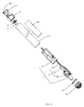
- a first embodiment of the present invention is to provide an electronic cigarette, comprising a cigarette body having a inhaling rod 90 and a battery rod 91.
- the cigarette body is installed with a retractable connecting device 7.
- the connecting device 7 is retractably disposed in the cigarette body so as to be hidden therein. When not in use, the connecting device 7 is foldably retracted to be completely hidden within the cigarette body together. When in use, the connecting device 7 is being pulled away to extend to a predetermined length, whereby electrically connecting the electronic cigarette to an external electronic device or power.
- the connecting device 7 is intended to charge the electronic cigarette and to transmit data as well, such as multimedia data, so as to satisfy requirements of multi functions of the electronic cigarette.
- the connecting device 7 at least comprises a connector 71 and a conductor 72 of which a length is extendable.
- the connector 71 is one of a universal serial bus (USB) connector, a peg-type, a pin-type or other appropriate connector.
- USB universal serial bus
- a preferable embodiment described below is exemplified by the USB connector 71 in order to achieve the object of charging the electronic cigarette.
- the inhaling rod 90 comprises an inhaling cylinder 1, an atomizing device 2 for atomizing a cigarette liquid, a cigarette liquid storing cup 3 for storing the cigarette liquid, an inhaling nozzle 4, and a male connecting element 5 for connecting the battery rod 91.
- the inhaling cylinder 1 is a hollow elongated tube structure, and the inhaling nozzle 4 and the male connecting element 5 are mounted to opposite end portions of the inhaling cylinder 1.
- the inhaling nozzle 4 has a substantially cylindrical body 41, which is internally hollow and has an inhaling hole 42 penetrating the cylindrical body 41 in an axial direction thereof.
- the inhaling nozzle 4 is made of a resilient material, and is detachably plugged into a top end of the inhaling cylinder 1.
- the male connecting element 5 made of a flexible material, is disposed at a bottom of the inhaling cylinder 1 and has a shape fitted to the inhaling cylinder 1.
- the male connecting element 5 is substantially shaped as a round cover being internally hollow, and has multiple air inlets 51 formed at a bottom thereof along peripheral rims of the male connecting element 5 for allowing the outside air to flow in the inhaling cylinder 1.
- a positioning step 52 is formed by extending outward radially from the bottom of the male connecting element 5 for abutting against the bottom of the inhaling cylinder 1.
- a first accommodating chamber 53 is formed on the bottom of the male connecting element 5 for being snugly mounted onto the battery rod 91.
- Electrode slots 54 and air vents 55 are respectively formed on a middle portion of the male connecting element 5 and penetrate the male connecting element 5 in an axial direction thereof.
- a positioning projection 56 is formed on the bottom of the male connecting element 5 and extends outward in the axial direction for being inserted into the battery rod 91.
- the inhaling cylinder 1 further comprises an atomizer first electrode element 17 and an atomizer second electrode element 19 for electrically connecting electrodes of the battery rod 91. Both of the atomizer first and second electrode elements 17 and 19 are disposed in the male connecting element 5.
- the atomizer first electrode element 17 is a flexibly deformable metal sheet and has a soldering plate 171 at one end thereof, the soldering plate 171 defining a soldering hole, a flexible contact plate 172 being flexibly deformable and formed at another end thereof, and an engaging plate 173 being flexibly deformable and formed at a middle of the atomizer first electrode element 17 for engaging with the male connecting element 5.
- the atomizer second electrode element 19 has a structure same as that of the atomizer first electrode element 17.
- the atomizing device 2 comprises an atomizer 21 installed in the inhaling rod 90, an atomizer switch27, a switch base 28, and a control circuit unit for controlling the atomizer 21.
- the atomizer 21 is intended to atomize the cigarette liquid to be smoke, and comprises a heating element 211 and fiber elements 212.
- the heating element 211 is wound around the fiber elements 212 and held in a cigarette liquid storing cup 3.
- the fiber elements 212 are intended to absorb the cigarette liquid for the heating element 211 to heat and atomize.
- the fiber elements 212 function as a sponge that is capable of absorbing and preserving water, and are made of glass fiber or a material having characters of absorbing and isolating liquid, such as cotton, and have a tubular shape. In this embodiment, the number of the fiber elements 212 is three (not limited thereby).
- the three fiber elements 212 as a whole are disposed in the cigarette liquid storing cup 3.
- the heating element 211 is wound around outer surfaces of the whole three fiber element 212, wherein two opposite ends of the heating element 211 respectively extend out of the cigarette liquid storing cup 3 for electrically connecting with the atomizer first electrode element 17 and the atomizer second electrode element 19 of the male connecting element 5.
- the cigarette liquid storing cup 3 comprises a cup seat 31, a cup lid 33, a guiding tube 35, a liquid storing element 37, and a positioning tube 39.
- the cup seat 31 and cup lid 33 both are spaced apart from each other at a predetermined space and are in snug-fit engagement with inner walls of the inhaling cylinder 1.
- the guiding tube 35 is mounted between the cup seat 31 and the cup lid 33.
- the liquid storing element 37 is disposed outside the guiding tube 35 between the cup seat 31 and the cup lid 33.
- the positioning tube 39 is intended to position the atomizer 21.
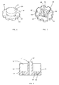
- the cup seat 31 (referring to FIGS. 3 , 4 and 8 ) has a cylindrical cup structure, a round side wall 318, a round cup bottom 319, a positioning pillar 311 extends in an axial direction of cup seat 31 from a middle of the cup bottom 319, wherein the round side wall 318 and the positioning pillar 311 cooperatively define a round internal chamber 317.
- An air channel 312 is formed in the positioning pillar 311 and penetrates the positioning pillar 311 and the bottom cup 319 in its axial direction.
- a plurality of threading channels 313 are formed on and penetrate the cup bottom 319 for the heating element 211 to pass through.
- An outer surface of the side wall 318 is formed with a jam-fit ring 314.
- the cup seat 31 is snugly fitted to an inner wall of the inhaling cylinder 1 with the side wall 318 and the jam-fit ring 314.
- the cup lid 33 (referring to FIGS. 3 , 4 , 6 and 7 ) is made of silica gel, and has a shape and size corresponding to the inner wall of the inhaling cylinder 1.
- the cup lid 33 is a hollow cylindrical lid structure, and has a side wall 338 and an upper wall 339 both cooperatively define a circular internal cavity 337 having an inner diameter greater than an outer diameter of the guiding tube 35 in order for flow of smoke.
- a plurality of air vents 336 are formed on a side wall of the cup lid 33 and communicate with the circular internal cavity 337.
- a plurality of ribs 335 are formed on the upper wall 339 and located in the circular internal cavity 337.
- ribs 335 there are three ribs 335 radially disposed on a middle portion of the upper wall 339, whereby when the guiding tube 35 is engaged with the ribs 224, a top end of the guiding tube 35 and the upper wall 339 jointly form a gap as a venting path 334 communicating with the circular internal cavity 337.
- a bottom of the side wall 338 extends radially outward to form a flange portion 333 which has multiple arc cutouts 332 and thus render the flange portion 333 serrated.
- An outer diameter of the flange portion 333 is slightly greater than an inner diameter of the inhaling cylinder 1.
- the cup lid 33 is snugly fitted with the inner wall of the inhaling cylinder 1 through the flange portion 333.
- the circular internal cavity 337 of the cup lid 33 corresponds to the positioning pillar 311 of the cup seat 31 and both respectively position the opposite ends of the guiding tube 35.
- the flange portion 333 of the cup lid 33 and the round internal chamber 317 of the cup seat 31 respectively fix two opposite ends of the liquid storing element 37.
- the guiding tube 35 (referring to FIGS. 3 and 4 ) is intended to support the liquid storing element 37 and the fiber elements 212 and limit the height of the cigarette liquid storing cup 3, and further functions as a path to outside of the inhaling cylinder 1 for the flow of smoke produced by the atomizer 21 atomizing the cigarette liquid.
- the guiding tube 35 is an insulating hollow cylinder, made of a plastic or fiber material, such as a fiberglass sleeve.
- the guiding tube 35 has top and bottom ends, wherein the top end is mounted in the circular internal cavity 337 of the cup lid 33, and the bottom end is snugly mounted to the positioning pillar 311 of the cup seat 31.
- the guiding tube 35 is formed with a retaining slot 351 penetrating side walls of the guiding tube 35 in a radial direction for retaining the fiber elements 212.
- the fiber elements 212 are fixed in the retaining slot 351 with two ends of the fiber elements 212 abutting against the liquid storing element 37 so as to absorb the cigarette liquid for the heating element 211 to atomize.
- the liquid storing element 37 (referring to FIGS. 3 and 4 ) is intended to absorb and store the cigarette liquid in the cigarette liquid storing cup 3 so as to allow the atomizer 2 to atomize the cigarette liquid.
- the liquid storing element 37 functions as a sponge that is capable of absorbing and preserving water, and is made of glass fiber or a material having characters of absorbing and isolating liquid, such as cotton.
- the liquid storing element 37 is a hollow cylindrical structure and is disposed outside the guiding tube 35. One end of the liquid storing element 37 is inserted in the round internal chamber 317 of the cup seat 31 and the other end abuts against the bottom of the cup lid 33 such as the liquid storing element 37 is disposed between the cup seat 31 and the cup lid 33. Two ends of the fiber elements 212 abut against inner walls of the liquid storing element 37 to absorb the cigarette liquid for the heating element 211 to atomize.
- the positioning tube 39 (referring to FIGS. 3 and 4 ) is intended to locate a position of the atomizer 21 with respect to the guiding tube 354.
- the positioning tube 39 is an insulating hollow cylinder being mountable onto outer walls of the guiding tube 35, and is made of a plastic or fiber material, such as a fiberglass sleeve.
- the positioning tube 39 and the guiding tube 35 are in interference fit with each other.
- a bottom of the positioning tube 39 abuts against the atomizer 21 to prevent the atomizer 21 from moving in an axial direction of the guiding tube 35.
- the cigarette liquid storing cup 3 defines a smoke path therein that is formed by the air channel 312 of the cup seat 31, a hollow passageway of the guiding tube 35, the venting path 334 of the cup lid 33, the circular internal cavity 337 and air vents 336 all together.
- the battery rod 91 comprises a barrel 910, a female connecting element 911 and a bottom case 912 respectively mounted to opposite ends of the barrel 910, a battery 913 installed in the barrel 910, and a battery first electrode element 914 and a battery second electrode 915 electrically connected to two electrodes of the battery 913.
- the female connecting element 911 is configured to mate with the male connecting element 5, and is made of a flexible plastic material.
- the female connecting element 911 is mounted to one end of the male connecting element 5 so as to connect the inhaling rod 90 and the battery rod 91.
- the female connecting element 911 is substantially shaped as a round cover, and comprises a side wall 9111, an upper wall 9112, an internal chamber 9119 is defined by the side wall 9111 and the upper wall 9112, a locating step 9113 is formed on the side wall 9111 adjacent to the upper wall 9112 and extends outward radially from the female connecting element 911 for fitting to the barrel 910, and an inserting peg 9114 is disposed on the upper wall 9112 and extends outward in an axial direction of the female connecting element 911 for being inserted into the first accommodating chamber 53 of the male connecting element 5.
- the upper wall 9112 is concavely formed with a plurality of positioning grooves 9115 for receiving the positioning projection 56 of the male connecting element 5.
- Threading holes 9116 are formed in and penetrate the female connecting element 911 in the axial direction, and two electrode slits 9117 and internal channels 9118 extend in the axial direction for positioning the battery first electrode element 914 and the battery second electrode element 915.
- the two internal channels 9118 for the insertion of the atomizer first and second electrode elements 17 and 19 with which the battery first and second electrode elements 914 and 915 are in flexible contact in the internal channels 9118.
- the bottom case 912 is mounted to the bottom end of the barrel 910 for sealing the USB connector 71.
- the bottom case 912 is further equipped with a sealing ring 916. It is understandable that to prevent the bottom case 912 from coming off the barrel 910 or lost after being pulled away, the bottom case 912 is further coupled with a coupling strap to connect the barrel 910.
- the coupling strap is capable of being disposed in the barrel 910 or integrally formed with a connecting portion or other connecting structure in order to mount the bottom case 912 onto the barrel.
- the battery first and second electrode elements 914 and 915 are respectively positioned in the electrode slits 9117.
- the battery first electrode element 914 is a flexibly deformable metal sheet, and has a soldering plate 9141 of a soldering hole at one end of the battery first electrode element 914, a flexible contact plate 9142 being flexibly deformable and formed at another end thereof, and an engaging plate 9143 being flexibly deformable and formed at a middle thereof for engaging with the female connecting element 911.
- the battery second electrode element 915 has a structure same as that of the battery first electrode element 914.
- the battery first and second electrode elements 914 and 915 of the female connecting element 911 are in flexibly contact with the atomizer first and second electrode elements 17 and 19 whereby realizing electrical connection.
- the battery first and second electrode elements 914 and 915 respectively electrically connect the positive and negative electrodes of the battery 913 through the soldering plates 9141 and soldering holes.
- the atomizer first and second electrode elements 17 and 19 are in flexible contact with the battery first and second electrode elements 914 and 915 through the flexible contact plates thereof to realize electrical connection. Accordingly, the electronic cigarette is capable of being assembled conveniently with a simplified craft and providing a reliable electrical connection.
- the atomizer switch 27 and the switch base 28 are disposed in the battery rod 91.
- the atomizer switch 27 is disposed in the switch base 28, while the switch base 28 is disposed in the internal chamber 9119 of the female connecting element 911.
- Two electrodes of the atomizer switch 27 are electrically connected to the battery first and second electrode elements 914 and 915 through two wires (not shown).
- the atomizer switch 27 is a pneumatic type switch that is switchable according to pneumatic vibration for power on or off.
- the atomizer switch 27 and the battery 913 are electrically connected to the control circuit unit.
- the connecting device 7 has the connecting device 71, a conductor 72, and a support base 73.
- the connecting device 7 is disposed in the battery rod 91.
- the connecting device 71 is intended to connect an external power in order to charge the battery 911.
- the USB connector 71 is also capable of transmitting, downloading, or storing multimedia data when the electronic cigarette is equipped with portable storage devices, MP3, MP4 or other multimedia functions.
- the connecting device 71 is mounted in the battery rod 91 through the support base 73.
- the support base 73 is being substantially cylindrical, and defines an accommodating chamber 731 therein configured to receive the connecting device 71 and the conductor 72.
- the support base 73 is further formed with two conductor positioning elements 735 for positioning the conductor 72.
- the two conductor positioning elements 735 are disposed on a side wall of the support base 73 and each is exemplified by a screw post having internal screw threads.
- a positioning stage 736 is radially formed on an outer wall of a front portion of the support base 73 for matching with a bottom of the barrel 910.
- a bottom board 737 is formed at a bottom of the support base 73, and defines a through hole 738 and an opening 739 therein.
- the outer wall of the support base 73 is formed with a conductor slit (not labeled).
- the first accommodating chamber 731 comprises a front portion 7311, a middle portion 7312, and a rear portion 7313 all connected with each other in sequence.
- the front portion 7311 is cylindrical for allowing the USB connector 71 and the conductor 72 to extend out of or retract to the support base 73.
- the middle portion 7312 is being substantially cylindrical or other shapes and extends outwards from a bottom surface of the front portion 7311 in an axial direction of the support base 73.
- the USB connector 71 is wedged into the middle portion 7312.
- the rear portion 7313 is intended to accommodate the conductor 72 when the conductor 72 is being retracted.
- the rear portion 7313 is formed by the bottom board 318 and two parallel clamping boards (not shown) extending in the axial direction.
- the rear portion 7313 is hollow cylindrical or has other shapes for the purpose of accommodating the conductor 72 and allowing the conductor 72 to freely move therein.
- a penetrating hole is formed between the middle portion 7312 and the rear portion 7313.
- An outer wall of the front portion 7311 is fitted with the inner wall of the barrel 910.
- the support base 73 is mounted in the barrel 910 through a snug-fit of the outer wall of the front portion 7311 and the barrel 910, and is positioned by the positioning stage 736 (referring to FIGS. 2 , 21, and 22 ).
- the conductor positioning elements 735 are disposed on an outer side of the middle portion 7312 of the first accommodating chamber 731 and integrated with the support base 73.
- the conductor 72 comprises a movable conductor 721, a fixing conductor 722, and a coupling element 723 for coupling the movable conductor 721 and the fixing conductor 722.
- the coupling element 723 is positioned by an inner wall or outer wall of the first accommodating chamber 731 so as to retain the fixing conductor 722.
- One end of the movable conductor 721 is electrically connected to the fixing conductor 722 through the coupling element 723.
- the other end of the movable conductor 721 is electrically connected to the USB connector 71.
- the fixing conductor 722 is electrically connected to the movable conductor 721 through the coupling element 723. Another end of the fixing conductor 722 is attached on the outer wall of the support base 73 along the conductor slit to pass through the opening 739 and then electrically connect the control circuit unit.
- the fixing conductor 722 is fixed in the battery rod 91 without being retracted or extended.
- the coupling element 723 is substantially U-shaped and forms two mounting holes at opposite sides thereof for mounting the conductor positioning elements 735.
- the coupling element 723 is fixedly mounted onto the conductor positioning elements 735, with screws screwed in the conductor positioning elements 735.
- the coupling element 735 is capable of having other shapes and being mounted in other ways. Therefore, the fixing conductor 722 of the conductor 72 is being positioned and retained in place so as to prevent the electrical connection of the conductor 72 and the control circuit unit from being affected by the movable conductor when the moveable conductor 721 is being drawn.
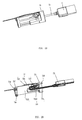
- the USB connector 71 When the connecting device 7 is not in use, the USB connector 71 is manually depressed into the support base 73, and the bottom case 912 is being mounted, and thus the moveable conductor 721 is disposed in a conductor receiving slot 732 formed in the support base 73 (referring to FIG. 18 ).
- the connecting device 7 When the connecting device 7 is in use, first remove the bottom case 912, and then pull the USB connector 71 away of the support base 73 to come out of the barrel 910, whereby one end of the moveable conductor 721 reaches out of the barrel 910 from the first accommodating chamber 731 in conjunction with the USB connector 71 (referring to FIG. 20 ), and the movable conductor 721 brings the USB conductor 71 to connect with the external electronic device or power within a predetermined distance.
- the number of the fixing conductor 722 is three, the three fixing conductors 722 respectively standing for a positive wire, a negative wire, and a signal wire for respectively connecting with respective electrodes of the control circuit unit.
- the connecting device 71 and the conductor 72 are disposed in the battery rod 91, and therefore enables a convenient usage and beautifies the electronic cigarette.
- the support base 73 defines the first accommodating chamber 731 for accommodating the USB connector 71 and the conductor 72 in a manner that the USB connector 71 and the conductor 72 are capable of freely moving therein.
- the inhaling rod 90 and the battery rod 91 are capable of being engaged or plugged together.
- the inhaling rod 90 and the battery rod 91 are detachably connected with each other through the male connecting element 5 snugly plugged with the female connecting element 911 in a convenient way.
- the electronic cigarette of the present invention is an one-piece element such that the inhaling cylinder 1 of the inhaling rod 90 and the barrel 910 of the battery rod 91 are integrally formed as an one-piece case body.
- the inhaling cylinder 1, the barrel 910, and the inhaling nozzle 4 are all integrally formed.
Landscapes
- Health & Medical Sciences (AREA)
- Engineering & Computer Science (AREA)
- Biomedical Technology (AREA)
- Heart & Thoracic Surgery (AREA)
- Veterinary Medicine (AREA)
- Bioinformatics & Cheminformatics (AREA)
- Pulmonology (AREA)
- Anesthesiology (AREA)
- Public Health (AREA)
- General Health & Medical Sciences (AREA)
- Hematology (AREA)
- Life Sciences & Earth Sciences (AREA)
- Animal Behavior & Ethology (AREA)
- General Chemical & Material Sciences (AREA)
- Chemical & Material Sciences (AREA)
- Chemical Kinetics & Catalysis (AREA)
- Battery Mounting, Suspending (AREA)
- Charge And Discharge Circuits For Batteries Or The Like (AREA)
Applications Claiming Priority (1)
| Application Number | Priority Date | Filing Date | Title |
|---|---|---|---|
| PCT/CN2012/078360 WO2014008623A1 (fr) | 2012-07-09 | 2012-07-09 | Cigarette électronique |
Publications (3)
| Publication Number | Publication Date |
|---|---|
| EP2870887A1 true EP2870887A1 (fr) | 2015-05-13 |
| EP2870887A4 EP2870887A4 (fr) | 2016-05-18 |
| EP2870887B1 EP2870887B1 (fr) | 2017-06-28 |
Family
ID=49877567
Family Applications (1)
| Application Number | Title | Priority Date | Filing Date |
|---|---|---|---|
| EP12880826.8A Not-in-force EP2870887B1 (fr) | 2012-07-09 | 2012-07-09 | Cigarette électronique |
Country Status (9)
| Country | Link |
|---|---|
| US (1) | US9386805B2 (fr) |
| EP (1) | EP2870887B1 (fr) |
| JP (1) | JP5935144B2 (fr) |
| KR (1) | KR101802616B1 (fr) |
| CN (1) | CN104470385B (fr) |
| AU (1) | AU2012385404B2 (fr) |
| CA (1) | CA2878505A1 (fr) |
| RU (1) | RU2598567C2 (fr) |
| WO (1) | WO2014008623A1 (fr) |
Cited By (2)
| Publication number | Priority date | Publication date | Assignee | Title |
|---|---|---|---|---|
| EP2967149B1 (fr) | 2013-03-15 | 2018-08-15 | R. J. Reynolds Tobacco Company | Cartouche et corps de commande d'un dispositif de diffusion d'aérosol comprenant un mécanisme antirotation, et procédé associé |
| EP3487333B1 (fr) | 2016-07-25 | 2021-06-09 | Fontem Holdings 1 B.V. | Partie d'alimentation électrique de cigarette électronique |
Families Citing this family (121)
| Publication number | Priority date | Publication date | Assignee | Title |
|---|---|---|---|---|
| US10244793B2 (en) | 2005-07-19 | 2019-04-02 | Juul Labs, Inc. | Devices for vaporization of a substance |
| US11344683B2 (en) | 2010-05-15 | 2022-05-31 | Rai Strategic Holdings, Inc. | Vaporizer related systems, methods, and apparatus |
| US9999250B2 (en) | 2010-05-15 | 2018-06-19 | Rai Strategic Holdings, Inc. | Vaporizer related systems, methods, and apparatus |
| US10159278B2 (en) | 2010-05-15 | 2018-12-25 | Rai Strategic Holdings, Inc. | Assembly directed airflow |
| US8757147B2 (en) | 2010-05-15 | 2014-06-24 | Minusa Holdings Llc | Personal vaporizing inhaler with internal light source |
| US9095175B2 (en) | 2010-05-15 | 2015-08-04 | R. J. Reynolds Tobacco Company | Data logging personal vaporizing inhaler |
| US9861772B2 (en) | 2010-05-15 | 2018-01-09 | Rai Strategic Holdings, Inc. | Personal vaporizing inhaler cartridge |
| US9743691B2 (en) | 2010-05-15 | 2017-08-29 | Rai Strategic Holdings, Inc. | Vaporizer configuration, control, and reporting |
| US9259035B2 (en) | 2010-05-15 | 2016-02-16 | R. J. Reynolds Tobacco Company | Solderless personal vaporizing inhaler |
| US10136672B2 (en) | 2010-05-15 | 2018-11-27 | Rai Strategic Holdings, Inc. | Solderless directly written heating elements |
| US10517530B2 (en) | 2012-08-28 | 2019-12-31 | Juul Labs, Inc. | Methods and devices for delivering and monitoring of tobacco, nicotine, or other substances |
| CN104010534B (zh) * | 2012-11-12 | 2016-04-20 | 惠州市吉瑞科技有限公司 | 电子烟装置、电子烟及其雾化装置 |
| US10154691B2 (en) | 2012-11-26 | 2018-12-18 | Nu Mark Innovations Ltd. | Bonding for an electronic cigarette cartridge |
| US10034988B2 (en) | 2012-11-28 | 2018-07-31 | Fontem Holdings I B.V. | Methods and devices for compound delivery |
| US10279934B2 (en) | 2013-03-15 | 2019-05-07 | Juul Labs, Inc. | Fillable vaporizer cartridge and method of filling |
| US10653180B2 (en) | 2013-06-14 | 2020-05-19 | Juul Labs, Inc. | Multiple heating elements with separate vaporizable materials in an electric vaporization device |
| KR102490695B1 (ko) | 2013-05-06 | 2023-01-19 | 쥴 랩스, 인크. | 에어로졸 장치를 위한 니코틴 염 제제 및 그 방법 |
| USD809189S1 (en) * | 2013-08-23 | 2018-01-30 | Kimree Hi-Tech Inc | Electronic cigarette |
| US10194693B2 (en) | 2013-09-20 | 2019-02-05 | Fontem Holdings 1 B.V. | Aerosol generating device |
| WO2015042799A1 (fr) * | 2013-09-25 | 2015-04-02 | 吉瑞高新科技股份有限公司 | Ensemble tige de batterie, cigarette électronique et appareil de charge de cigarette électronique |
| US10039321B2 (en) | 2013-11-12 | 2018-08-07 | Vmr Products Llc | Vaporizer |
| US20160374393A1 (en) * | 2013-11-28 | 2016-12-29 | Hk Triangle Co., Limited | Electronic cigarette atomizer |
| EP4552512A3 (fr) | 2013-12-05 | 2025-07-02 | Juul Labs, Inc. | Formulations liquides de nicotine pour dispositifs d'aérosol et procédés associés |
| USD842536S1 (en) | 2016-07-28 | 2019-03-05 | Juul Labs, Inc. | Vaporizer cartridge |
| US10076139B2 (en) | 2013-12-23 | 2018-09-18 | Juul Labs, Inc. | Vaporizer apparatus |
| US20160366947A1 (en) | 2013-12-23 | 2016-12-22 | James Monsees | Vaporizer apparatus |
| USD825102S1 (en) | 2016-07-28 | 2018-08-07 | Juul Labs, Inc. | Vaporizer device with cartridge |
| US10058129B2 (en) | 2013-12-23 | 2018-08-28 | Juul Labs, Inc. | Vaporization device systems and methods |
| US9549573B2 (en) * | 2013-12-23 | 2017-01-24 | Pax Labs, Inc. | Vaporization device systems and methods |
| KR102267997B1 (ko) | 2013-12-23 | 2021-06-23 | 쥴 랩스, 인크. | 기화 디바이스 시스템 및 방법 |
| US10159282B2 (en) | 2013-12-23 | 2018-12-25 | Juul Labs, Inc. | Cartridge for use with a vaporizer device |
| CN203762295U (zh) * | 2014-01-14 | 2014-08-13 | 深圳市合元科技有限公司 | 电子烟用电池组件及电子烟 |
| WO2015106440A1 (fr) * | 2014-01-17 | 2015-07-23 | 深圳市麦克韦尔科技有限公司 | Structure de connexion de cigarette électronique et cigarette électronique |
| US9993024B2 (en) * | 2014-01-22 | 2018-06-12 | Huizhou Kimree Technology Co., Ltd. Shenzhen Branch | Battery rod and electronic cigarette |
| EP2907398A1 (fr) * | 2014-01-27 | 2015-08-19 | Shenzhen Smaco Technology Limited | Cigarette électronique jetable |
| TWI751467B (zh) | 2014-02-06 | 2022-01-01 | 美商尤爾實驗室有限公司 | 產生可吸入氣膠之裝置及用於該裝置之可分離匣 |
| US10709173B2 (en) | 2014-02-06 | 2020-07-14 | Juul Labs, Inc. | Vaporizer apparatus |
| US12279646B2 (en) | 2014-02-06 | 2025-04-22 | Juul Labs, Inc. | Cartridge of vaporization device systems having unequal transverse cartridge dimensions |
| CN203723447U (zh) * | 2014-02-12 | 2014-07-23 | 刘秋明 | 一种雾化组件以及电子烟 |
| DE202014001718U1 (de) * | 2014-02-27 | 2015-05-28 | Xeo Holding GmbH | Rauchvorrichtung |
| US10111467B1 (en) | 2014-03-24 | 2018-10-30 | Scott M. Arnel | Wearable electronic simulated smoking device with interchangeable vaporization cartridges |
| US9820508B2 (en) * | 2014-03-24 | 2017-11-21 | Scott M. Arnel | Wearable electronic simulated smoking device |
| USD743622S1 (en) * | 2014-04-02 | 2015-11-17 | Yariv Alima | Vaporizer body |
| CN103892467B (zh) * | 2014-04-02 | 2016-04-20 | 林光榕 | 椭圆形电子烟及其制造工艺 |
| DE102014207277A1 (de) * | 2014-04-15 | 2015-10-15 | Hauni Maschinenbau Ag | Elektrisches Rauchprodukt sowie Vorrichtung zur Herstellung von elektrischen Rauchprodukten |
| WO2015175979A1 (fr) | 2014-05-16 | 2015-11-19 | Pax Labs, Inc. | Systèmes et procédés de pulvérisation par aérosol d'un matériau pouvant être fumé |
| WO2016011574A1 (fr) * | 2014-07-21 | 2016-01-28 | 惠州市吉瑞科技有限公司 | Cigarette électronique |
| US20160128387A1 (en) * | 2014-08-29 | 2016-05-12 | Shenzhen Smoore Technology Limited | Electronic cigarette and method for manufacturing electronic cigarette |
| USD723732S1 (en) * | 2014-09-03 | 2015-03-03 | Atmos Nation, LLC | Herb heating chamber |
| EP3200633B1 (fr) | 2014-10-02 | 2025-04-02 | Cue Vapor Ltd | Cigarette électronique à réservoir jetable, procédé de fabrication et procédé d'utilisation |
| CN106686993A (zh) * | 2014-11-14 | 2017-05-17 | 惠州市吉瑞科技有限公司深圳分公司 | 一种电子烟以及电子烟雾化控制方法 |
| KR102627987B1 (ko) | 2014-12-05 | 2024-01-22 | 쥴 랩스, 인크. | 교정된 투여량 제어 |
| CN204444245U (zh) * | 2015-01-05 | 2015-07-08 | 深圳市合元科技有限公司 | 可更换的雾化单元和包括该雾化单元的雾化器及电子烟 |
| GB201501429D0 (en) * | 2015-01-28 | 2015-03-11 | British American Tobacco Co | Apparatus for heating aerosol generating material |
| EP3056099B1 (fr) * | 2015-02-16 | 2018-04-04 | Fontem Holdings 1 B.V. | Dispositif à fumer électronique avec une connexion de verrouillage encliquetable |
| CN104824848B (zh) * | 2015-03-10 | 2018-04-03 | 深圳麦克韦尔股份有限公司 | 电子烟 |
| CN107427083A (zh) * | 2015-04-02 | 2017-12-01 | 菲利普莫里斯生产公司 | 包含模块和电操作气溶胶生成系统的成套装置 |
| USD874059S1 (en) | 2015-04-22 | 2020-01-28 | Altria Client Servies Llc | Electronic vaping device |
| US10671031B2 (en) | 2015-04-22 | 2020-06-02 | Altria Client Services Llc | Body gesture control system for button-less vaping |
| US10701981B2 (en) | 2015-04-22 | 2020-07-07 | Altria Client Services Llc | Pod assembly and e-vapor apparatus including the same |
| USD980507S1 (en) | 2015-04-22 | 2023-03-07 | Altria Client Services Llc | Electronic vaping device |
| USD1052163S1 (en) | 2015-04-22 | 2024-11-19 | Altria Client Services Llc | Electronic vaping device |
| US10064432B2 (en) | 2015-04-22 | 2018-09-04 | Altria Client Services Llc | Pod assembly, dispensing body, and E-vapor apparatus including the same |
| USD874720S1 (en) | 2015-04-22 | 2020-02-04 | Altria Client Services, Llc | Pod for an electronic vaping device |
| US10687554B2 (en) | 2015-04-22 | 2020-06-23 | Altria Client Services Llc | Connection device, cartridge and electronic vaping device |
| US10104913B2 (en) | 2015-04-22 | 2018-10-23 | Altria Client Services Llc | Pod assembly, dispensing body, and E-vapor apparatus including the same |
| US10010114B2 (en) | 2015-06-25 | 2018-07-03 | Altria Client Services Llc | Charger assembly and charging system for an electronic vaping device |
| CN104983073A (zh) * | 2015-07-07 | 2015-10-21 | 深圳市赛尔美电子科技有限公司 | 一种卷烟蒸馏装置 |
| KR102405408B1 (ko) * | 2015-07-16 | 2022-06-07 | 삼성전자 주식회사 | 전차원 다중 입출력 시스템에서 채널 상태 정보를 송수신하는 방법 및 장치 |
| EP3821724B1 (fr) | 2015-12-18 | 2023-06-07 | JT International SA | Cartouche et vaporisateur personnel |
| CN205305994U (zh) * | 2015-12-24 | 2016-06-15 | 林光榕 | 电子烟雾化装置 |
| WO2017139675A1 (fr) | 2016-02-11 | 2017-08-17 | Pax Labs, Inc. | Cartouches fixées de manière sure pour des dispositifs de vaporisation |
| MX377347B (es) | 2016-02-11 | 2025-03-07 | Juul Labs Inc | Cartucho rellenable de vaporizador y metodo de relleno |
| US11412781B2 (en) * | 2016-02-12 | 2022-08-16 | Rai Strategic Holdings, Inc. | Adapters for refilling an aerosol delivery device |
| US10912333B2 (en) | 2016-02-25 | 2021-02-09 | Juul Labs, Inc. | Vaporization device control systems and methods |
| US10405582B2 (en) | 2016-03-10 | 2019-09-10 | Pax Labs, Inc. | Vaporization device with lip sensing |
| US10264821B2 (en) | 2016-03-21 | 2019-04-23 | Altria Client Services Llc | Electronic vaping device |
| USD849996S1 (en) | 2016-06-16 | 2019-05-28 | Pax Labs, Inc. | Vaporizer cartridge |
| USD836541S1 (en) | 2016-06-23 | 2018-12-25 | Pax Labs, Inc. | Charging device |
| USD851830S1 (en) | 2016-06-23 | 2019-06-18 | Pax Labs, Inc. | Combined vaporizer tamp and pick tool |
| USD848057S1 (en) | 2016-06-23 | 2019-05-07 | Pax Labs, Inc. | Lid for a vaporizer |
| US10292426B2 (en) | 2016-06-24 | 2019-05-21 | Altria Client Services, Llc | E-vaping device cartridge with superabsorbent polymer |
| US10085485B2 (en) | 2016-07-06 | 2018-10-02 | Rai Strategic Holdings, Inc. | Aerosol delivery device with a reservoir housing and a vaporizer assembly |
| USD830298S1 (en) | 2016-07-29 | 2018-10-09 | Altria Client Services Llc | USB charging connector for electronic vaporizer |
| WO2018018599A1 (fr) * | 2016-07-29 | 2018-02-01 | 深圳麦克韦尔股份有限公司 | Cigarette électronique et atomiseur associé |
| US10729177B2 (en) * | 2016-07-31 | 2020-08-04 | Altria Client Services Llc | Electronic vaping device, battery section, and charger |
| JP7110181B2 (ja) * | 2016-09-15 | 2022-08-01 | フィリップ・モーリス・プロダクツ・ソシエテ・アノニム | エアロゾル発生装置 |
| US11660403B2 (en) | 2016-09-22 | 2023-05-30 | Juul Labs, Inc. | Leak-resistant vaporizer device |
| CN106235422A (zh) * | 2016-09-29 | 2016-12-21 | 深圳市博格科技有限公司 | 一种滴油式雾化器与电子烟 |
| CA173126S (en) * | 2016-09-30 | 2019-02-14 | Fontem Holdings 1 Bv | Electronic vaping device |
| CA3045815A1 (fr) | 2016-12-02 | 2018-06-07 | Vmr Products Llc | Vaporisateur combine |
| CA3046954C (fr) | 2016-12-12 | 2024-01-02 | Vmr Products Llc | Cartouche reutilisable pour vaporisateur |
| GB201700812D0 (en) | 2017-01-17 | 2017-03-01 | British American Tobacco Investments Ltd | Apparatus for heating smokable material |
| IL309409B1 (en) * | 2017-05-22 | 2026-02-01 | Altria Client Services Llc | An assembly of a pod, a dispensing body and an electronic vapor production device comprising them |
| USD887632S1 (en) | 2017-09-14 | 2020-06-16 | Pax Labs, Inc. | Vaporizer cartridge |
| CN109965349B (zh) * | 2017-12-27 | 2024-05-28 | 上海新型烟草制品研究院有限公司 | 一种电子烟 |
| TW201932031A (zh) | 2017-12-29 | 2019-08-16 | 瑞士商傑太日煙國際股份有限公司 | 吸菸裝置 |
| KR20190083581A (ko) | 2018-01-04 | 2019-07-12 | 홍성혁 | 궐련형 기화식 담배 장치 |
| US11986590B2 (en) | 2018-06-26 | 2024-05-21 | Juul Labs, Inc. | Vaporizer wicking elements including a hollow core |
| PL426350A1 (pl) * | 2018-07-18 | 2020-01-27 | Esmoking Institute Spółka Z Ograniczoną Odpowiedzialnością | Elektroniczny system dostarczania aerozolu |
| CN108813738A (zh) * | 2018-08-10 | 2018-11-16 | 陈志明 | 一种电子烟杆及电子烟 |
| CN108851252B (zh) * | 2018-09-25 | 2024-08-20 | 深圳市美深威科技有限公司 | 一种电子烟电池杆及电子烟 |
| EP3664630B1 (fr) | 2018-10-15 | 2022-02-16 | Juul Labs, Inc. | Élément chauffant |
| GB2580763B (en) | 2018-10-19 | 2023-02-22 | Juul Labs Inc | Vaporizer power system |
| JP6855434B2 (ja) | 2018-12-10 | 2021-04-07 | 有限会社ヘルス・アンド・ヒーリング・オペレーション | 電子タバコシステム |
| WO2020165949A1 (fr) * | 2019-02-12 | 2020-08-20 | 日本たばこ産業株式会社 | Cartouche pour inhalateur |
| EP3738450B1 (fr) * | 2019-05-13 | 2024-09-18 | Tuanfang Liu | Vaporisateur |
| US12369639B2 (en) | 2019-06-21 | 2025-07-29 | Imperial Tobacco Limited | Aerosol delivery device |
| WO2021089743A1 (fr) * | 2019-11-08 | 2021-05-14 | Nerudia Limited | Dispositif de charge et kit de substitution pour fumeurs |
| EP3838009A1 (fr) * | 2019-12-20 | 2021-06-23 | Nerudia Limited | Dispositif de chargement et kit de substitution du tabac |
| KR102423895B1 (ko) | 2019-11-25 | 2022-07-21 | 주식회사 케이티앤지 | 히터 조립체, 에어로졸 생성 장치 및 에어로졸 생성 시스템 |
| US11602171B2 (en) * | 2019-11-26 | 2023-03-14 | Tuanfang Liu | Electronic cigarette having leakproof device for preventing leakage of e-liquid |
| US11484065B2 (en) * | 2019-11-26 | 2022-11-01 | Tuanfang Liu | Electronic cigarette having an air regulating ring |
| CN211832820U (zh) * | 2019-12-02 | 2020-11-03 | 深圳麦克韦尔科技有限公司 | 一种电子雾化装置及其加热组件和发热结构 |
| WO2021113533A1 (fr) | 2019-12-04 | 2021-06-10 | Juul Labs, Inc. | Circuit d'entraînement à haute énergie pour un dispositif de chauffage de vaporisateur |
| US20210401051A1 (en) * | 2020-06-29 | 2021-12-30 | Shenzhen Eigate Technology Co., Ltd. | Atomizer |
| US11930861B2 (en) * | 2020-12-07 | 2024-03-19 | Rai Strategic Holdings, Inc. | Aerosol provision system with integrated charger |
| KR20220165327A (ko) | 2021-06-08 | 2022-12-15 | 이서현 | 캡슐형 전자담배 |
| CN217089623U (zh) * | 2021-12-15 | 2022-08-02 | 深圳沃德韦科技有限公司 | 电子雾化装置 |
| CN219515312U (zh) * | 2022-09-27 | 2023-08-15 | 深圳麦克韦尔科技有限公司 | 加热组件和气溶胶产生装置 |
| CN121587458A (zh) * | 2024-08-19 | 2026-03-03 | 尼科创业贸易有限公司 | 气溶胶供应装置 |
Family Cites Families (22)
| Publication number | Priority date | Publication date | Assignee | Title |
|---|---|---|---|---|
| AR002035A1 (es) * | 1995-04-20 | 1998-01-07 | Philip Morris Prod | Un cigarrillo, un cigarrillo y encendedor adaptados para cooperar entre si, un metodo para mejorar la entrega de aerosol de un cigarrillo, un material continuo de tabaco, un cigarrillo operativo, un metodo para manufacturar un material continuo, el material asi obtenido, un calentador, un metodo para formar un calentador y un sistema electrico para fumar |
| JP2000049918A (ja) * | 1998-08-03 | 2000-02-18 | Fujitsu I Network Systems Ltd | 携帯型電話機 |
| CN2591886Y (zh) * | 2002-12-28 | 2003-12-10 | 杨志刚 | 手机连线器 |
| US7632113B2 (en) * | 2003-11-17 | 2009-12-15 | Dpd Patent Trust Ltd. | Retractable USB stick |
| US6926554B2 (en) * | 2003-11-20 | 2005-08-09 | Creative Technology Limited | Portable device connection apparatus and system |
| US20070126290A1 (en) * | 2005-11-01 | 2007-06-07 | Jaynes Stephen R | Systems and methods for powering an electronic device from selectable power sources |
| KR20080030247A (ko) * | 2006-09-29 | 2008-04-04 | 엘지전자 주식회사 | 연결선의 수납이 가능한 마우스 |
| CN200997909Y (zh) * | 2006-12-15 | 2008-01-02 | 王玉民 | 一次性电子纯净香烟 |
| US20090283103A1 (en) * | 2008-05-13 | 2009-11-19 | Nielsen Michael D | Electronic vaporizing devices and docking stations |
| CN201408820Y (zh) * | 2009-04-28 | 2010-02-17 | 慈溪市依赛格电子科技有限公司 | 一种用于电子烟的充电装置 |
| JP2011087569A (ja) * | 2009-05-15 | 2011-05-06 | Jbs:Kk | 電子タバコ、および充電ユニット |
| CN101606758B (zh) * | 2009-07-14 | 2011-04-13 | 方晓林 | 电子烟 |
| TWM376063U (en) * | 2009-10-19 | 2010-03-11 | Multi Function Co Ltd | Charging/discharging device with hidden type USB plug |
| CN201830899U (zh) * | 2010-06-09 | 2011-05-18 | 李永海 | 电子香烟的供电装置 |
| CN201830900U (zh) * | 2010-06-09 | 2011-05-18 | 李永海 | 电子香烟的烟液雾化装置 |
| CN201733855U (zh) * | 2010-08-10 | 2011-02-09 | 刘翔 | 电子香烟 |
| CN102160906B (zh) * | 2010-11-01 | 2012-08-08 | 常州市富艾发进出口有限公司 | 口吸式便携雾化器 |
| KR20120057459A (ko) * | 2010-11-26 | 2012-06-05 | 이호준 | 컴퓨터와 인터페이스 하는 전자담배 |
| CN202112305U (zh) * | 2011-01-27 | 2012-01-18 | 文昌 | 具储存装置的多功能吸入式电子烟雾产生器 |
| KR101081481B1 (ko) * | 2011-06-13 | 2011-11-08 | 김형윤 | 전자담배용 무화기 일체형 카트리지 |
| UA67598U (en) * | 2011-08-26 | 2012-02-27 | Дмитрий Юрьевич Рогов | Electronic cigarette |
| RU115629U1 (ru) * | 2011-10-10 | 2012-05-10 | Сергей Павлович Кузьмин | Электронная сигарета |
-
2012
- 2012-07-09 CA CA2878505A patent/CA2878505A1/fr not_active Abandoned
- 2012-07-09 KR KR1020157003216A patent/KR101802616B1/ko not_active Expired - Fee Related
- 2012-07-09 JP JP2015520788A patent/JP5935144B2/ja not_active Expired - Fee Related
- 2012-07-09 EP EP12880826.8A patent/EP2870887B1/fr not_active Not-in-force
- 2012-07-09 AU AU2012385404A patent/AU2012385404B2/en not_active Expired - Fee Related
- 2012-07-09 WO PCT/CN2012/078360 patent/WO2014008623A1/fr not_active Ceased
- 2012-07-09 US US13/824,440 patent/US9386805B2/en not_active Expired - Fee Related
- 2012-07-09 CN CN201280071003.3A patent/CN104470385B/zh not_active Expired - Fee Related
- 2012-07-09 RU RU2015103964/12A patent/RU2598567C2/ru not_active IP Right Cessation
Cited By (5)
| Publication number | Priority date | Publication date | Assignee | Title |
|---|---|---|---|---|
| EP2967149B1 (fr) | 2013-03-15 | 2018-08-15 | R. J. Reynolds Tobacco Company | Cartouche et corps de commande d'un dispositif de diffusion d'aérosol comprenant un mécanisme antirotation, et procédé associé |
| US10492532B2 (en) | 2013-03-15 | 2019-12-03 | Rai Strategic Holdings, Inc. | Cartridge and control body of an aerosol delivery device including anti-rotation mechanism and related method |
| US11247006B2 (en) | 2013-03-15 | 2022-02-15 | Rai Strategic Holdings, Inc. | Cartridge and control body of an aerosol delivery device including anti-rotation mechanism and related method |
| EP2967149B2 (fr) † | 2013-03-15 | 2022-09-07 | RAI Strategic Holdings, Inc. | Cartouche et corps de commande d'un dispositif de diffusion d'aérosol comprenant un mécanisme antirotation, et procédé associé |
| EP3487333B1 (fr) | 2016-07-25 | 2021-06-09 | Fontem Holdings 1 B.V. | Partie d'alimentation électrique de cigarette électronique |
Also Published As
| Publication number | Publication date |
|---|---|
| JP5935144B2 (ja) | 2016-06-15 |
| RU2598567C2 (ru) | 2016-09-27 |
| CN104470385A (zh) | 2015-03-25 |
| CA2878505A1 (fr) | 2014-01-16 |
| KR101802616B1 (ko) | 2017-11-28 |
| US9386805B2 (en) | 2016-07-12 |
| KR20150030268A (ko) | 2015-03-19 |
| EP2870887B1 (fr) | 2017-06-28 |
| US20140007891A1 (en) | 2014-01-09 |
| JP2015523077A (ja) | 2015-08-13 |
| EP2870887A4 (fr) | 2016-05-18 |
| AU2012385404B2 (en) | 2017-04-27 |
| WO2014008623A1 (fr) | 2014-01-16 |
| RU2015103964A (ru) | 2015-09-10 |
| CN104470385B (zh) | 2017-04-19 |
| AU2012385404A1 (en) | 2015-02-26 |
Similar Documents
| Publication | Publication Date | Title |
|---|---|---|
| EP2870887B1 (fr) | Cigarette électronique | |
| US9364026B2 (en) | Electronic cigarette tightly engaged by expansion | |
| EP3369327B1 (fr) | Atomiseur, ensemble d'atomisation et inhalateur | |
| US9861133B2 (en) | Electronic cigarette | |
| US9532602B2 (en) | Electronic cigarette | |
| CN105636463B (zh) | 电池组件及电子烟 | |
| US9980511B2 (en) | Electronic cigarette, battery rod and atomizer | |
| US9364024B2 (en) | Electronic cigarette having a connector for magnetic connection | |
| KR101532361B1 (ko) | 차량용 유에스비 어댑터 | |
| EP3095336A1 (fr) | Ensemble batterie, cigarette électronique et procédé d'assemblage d'un ensemble batterie | |
| US20140251325A1 (en) | Electronic cigarette preventing its nozzle from falling off | |
| US7819704B1 (en) | Connector plug with movable conducting pole | |
| KR101786819B1 (ko) | 차량용 유에스비 충전기 | |
| USRE49183E1 (en) | Lamp socket adapter | |
| US11575237B2 (en) | Adapter | |
| CN211655026U (zh) | 一种可拆卸天线结构的路由器 | |
| CN211794325U (zh) | 一种电子烟 | |
| CN218721314U (zh) | 一种可隐藏充电接口的尾盖结构和手电筒 | |
| CN222656288U (zh) | 一种可自动伸缩的电子雾化装置 | |
| CN220172545U (zh) | 一种免线直插式usb香薰装置 |
Legal Events
| Date | Code | Title | Description |
|---|---|---|---|
| PUAI | Public reference made under article 153(3) epc to a published international application that has entered the european phase |
Free format text: ORIGINAL CODE: 0009012 |
|
| 17P | Request for examination filed |
Effective date: 20150209 |
|
| AK | Designated contracting states |
Kind code of ref document: A1 Designated state(s): AL AT BE BG CH CY CZ DE DK EE ES FI FR GB GR HR HU IE IS IT LI LT LU LV MC MK MT NL NO PL PT RO RS SE SI SK SM TR |
|
| AX | Request for extension of the european patent |
Extension state: BA ME |
|
| DAX | Request for extension of the european patent (deleted) | ||
| RA4 | Supplementary search report drawn up and despatched (corrected) |
Effective date: 20160415 |
|
| RIC1 | Information provided on ipc code assigned before grant |
Ipc: A24F 47/00 20060101AFI20160411BHEP |
|
| RAP1 | Party data changed (applicant data changed or rights of an application transferred) |
Owner name: HUIZHOU KIMREE TECHNOLOGY CO., LTD. SHENZHEN BRANC |
|
| GRAP | Despatch of communication of intention to grant a patent |
Free format text: ORIGINAL CODE: EPIDOSNIGR1 |
|
| STAA | Information on the status of an ep patent application or granted ep patent |
Free format text: STATUS: GRANT OF PATENT IS INTENDED |
|
| INTG | Intention to grant announced |
Effective date: 20170208 |
|
| RIN1 | Information on inventor provided before grant (corrected) |
Inventor name: LIU, QIUMING |
|
| GRAS | Grant fee paid |
Free format text: ORIGINAL CODE: EPIDOSNIGR3 |
|
| GRAA | (expected) grant |
Free format text: ORIGINAL CODE: 0009210 |
|
| STAA | Information on the status of an ep patent application or granted ep patent |
Free format text: STATUS: THE PATENT HAS BEEN GRANTED |
|
| AK | Designated contracting states |
Kind code of ref document: B1 Designated state(s): AL AT BE BG CH CY CZ DE DK EE ES FI FR GB GR HR HU IE IS IT LI LT LU LV MC MK MT NL NO PL PT RO RS SE SI SK SM TR |
|
| REG | Reference to a national code |
Ref country code: GB Ref legal event code: FG4D |
|
| REG | Reference to a national code |
Ref country code: CH Ref legal event code: EP |
|
| REG | Reference to a national code |
Ref country code: AT Ref legal event code: REF Ref document number: 904042 Country of ref document: AT Kind code of ref document: T Effective date: 20170715 |
|
| REG | Reference to a national code |
Ref country code: IE Ref legal event code: FG4D |
|
| REG | Reference to a national code |
Ref country code: DE Ref legal event code: R096 Ref document number: 602012034093 Country of ref document: DE |
|
| PG25 | Lapsed in a contracting state [announced via postgrant information from national office to epo] |
Ref country code: NO Free format text: LAPSE BECAUSE OF FAILURE TO SUBMIT A TRANSLATION OF THE DESCRIPTION OR TO PAY THE FEE WITHIN THE PRESCRIBED TIME-LIMIT Effective date: 20170928 Ref country code: FI Free format text: LAPSE BECAUSE OF FAILURE TO SUBMIT A TRANSLATION OF THE DESCRIPTION OR TO PAY THE FEE WITHIN THE PRESCRIBED TIME-LIMIT Effective date: 20170628 Ref country code: HR Free format text: LAPSE BECAUSE OF FAILURE TO SUBMIT A TRANSLATION OF THE DESCRIPTION OR TO PAY THE FEE WITHIN THE PRESCRIBED TIME-LIMIT Effective date: 20170628 Ref country code: GR Free format text: LAPSE BECAUSE OF FAILURE TO SUBMIT A TRANSLATION OF THE DESCRIPTION OR TO PAY THE FEE WITHIN THE PRESCRIBED TIME-LIMIT Effective date: 20170929 Ref country code: LT Free format text: LAPSE BECAUSE OF FAILURE TO SUBMIT A TRANSLATION OF THE DESCRIPTION OR TO PAY THE FEE WITHIN THE PRESCRIBED TIME-LIMIT Effective date: 20170628 |
|
| REG | Reference to a national code |
Ref country code: NL Ref legal event code: MP Effective date: 20170628 |
|
| REG | Reference to a national code |
Ref country code: LT Ref legal event code: MG4D |
|
| REG | Reference to a national code |
Ref country code: AT Ref legal event code: MK05 Ref document number: 904042 Country of ref document: AT Kind code of ref document: T Effective date: 20170628 |
|
| PG25 | Lapsed in a contracting state [announced via postgrant information from national office to epo] |
Ref country code: LV Free format text: LAPSE BECAUSE OF FAILURE TO SUBMIT A TRANSLATION OF THE DESCRIPTION OR TO PAY THE FEE WITHIN THE PRESCRIBED TIME-LIMIT Effective date: 20170628 Ref country code: RS Free format text: LAPSE BECAUSE OF FAILURE TO SUBMIT A TRANSLATION OF THE DESCRIPTION OR TO PAY THE FEE WITHIN THE PRESCRIBED TIME-LIMIT Effective date: 20170628 Ref country code: BG Free format text: LAPSE BECAUSE OF FAILURE TO SUBMIT A TRANSLATION OF THE DESCRIPTION OR TO PAY THE FEE WITHIN THE PRESCRIBED TIME-LIMIT Effective date: 20170928 Ref country code: NL Free format text: LAPSE BECAUSE OF FAILURE TO SUBMIT A TRANSLATION OF THE DESCRIPTION OR TO PAY THE FEE WITHIN THE PRESCRIBED TIME-LIMIT Effective date: 20170628 Ref country code: SE Free format text: LAPSE BECAUSE OF FAILURE TO SUBMIT A TRANSLATION OF THE DESCRIPTION OR TO PAY THE FEE WITHIN THE PRESCRIBED TIME-LIMIT Effective date: 20170628 |
|
| PG25 | Lapsed in a contracting state [announced via postgrant information from national office to epo] |
Ref country code: SK Free format text: LAPSE BECAUSE OF FAILURE TO SUBMIT A TRANSLATION OF THE DESCRIPTION OR TO PAY THE FEE WITHIN THE PRESCRIBED TIME-LIMIT Effective date: 20170628 Ref country code: RO Free format text: LAPSE BECAUSE OF FAILURE TO SUBMIT A TRANSLATION OF THE DESCRIPTION OR TO PAY THE FEE WITHIN THE PRESCRIBED TIME-LIMIT Effective date: 20170628 Ref country code: CZ Free format text: LAPSE BECAUSE OF FAILURE TO SUBMIT A TRANSLATION OF THE DESCRIPTION OR TO PAY THE FEE WITHIN THE PRESCRIBED TIME-LIMIT Effective date: 20170628 Ref country code: EE Free format text: LAPSE BECAUSE OF FAILURE TO SUBMIT A TRANSLATION OF THE DESCRIPTION OR TO PAY THE FEE WITHIN THE PRESCRIBED TIME-LIMIT Effective date: 20170628 Ref country code: AT Free format text: LAPSE BECAUSE OF FAILURE TO SUBMIT A TRANSLATION OF THE DESCRIPTION OR TO PAY THE FEE WITHIN THE PRESCRIBED TIME-LIMIT Effective date: 20170628 |
|
| REG | Reference to a national code |
Ref country code: DE Ref legal event code: R119 Ref document number: 602012034093 Country of ref document: DE |
|
| PG25 | Lapsed in a contracting state [announced via postgrant information from national office to epo] |
Ref country code: PL Free format text: LAPSE BECAUSE OF FAILURE TO SUBMIT A TRANSLATION OF THE DESCRIPTION OR TO PAY THE FEE WITHIN THE PRESCRIBED TIME-LIMIT Effective date: 20170628 Ref country code: SM Free format text: LAPSE BECAUSE OF FAILURE TO SUBMIT A TRANSLATION OF THE DESCRIPTION OR TO PAY THE FEE WITHIN THE PRESCRIBED TIME-LIMIT Effective date: 20170628 Ref country code: IS Free format text: LAPSE BECAUSE OF FAILURE TO SUBMIT A TRANSLATION OF THE DESCRIPTION OR TO PAY THE FEE WITHIN THE PRESCRIBED TIME-LIMIT Effective date: 20171028 Ref country code: ES Free format text: LAPSE BECAUSE OF FAILURE TO SUBMIT A TRANSLATION OF THE DESCRIPTION OR TO PAY THE FEE WITHIN THE PRESCRIBED TIME-LIMIT Effective date: 20170628 Ref country code: IT Free format text: LAPSE BECAUSE OF FAILURE TO SUBMIT A TRANSLATION OF THE DESCRIPTION OR TO PAY THE FEE WITHIN THE PRESCRIBED TIME-LIMIT Effective date: 20170628 |
|
| REG | Reference to a national code |
Ref country code: CH Ref legal event code: PL |
|
| PG25 | Lapsed in a contracting state [announced via postgrant information from national office to epo] |
Ref country code: MC Free format text: LAPSE BECAUSE OF FAILURE TO SUBMIT A TRANSLATION OF THE DESCRIPTION OR TO PAY THE FEE WITHIN THE PRESCRIBED TIME-LIMIT Effective date: 20170628 |
|
| REG | Reference to a national code |
Ref country code: IE Ref legal event code: MM4A |
|
| PG25 | Lapsed in a contracting state [announced via postgrant information from national office to epo] |
Ref country code: DK Free format text: LAPSE BECAUSE OF FAILURE TO SUBMIT A TRANSLATION OF THE DESCRIPTION OR TO PAY THE FEE WITHIN THE PRESCRIBED TIME-LIMIT Effective date: 20170628 Ref country code: LI Free format text: LAPSE BECAUSE OF NON-PAYMENT OF DUE FEES Effective date: 20170731 Ref country code: CH Free format text: LAPSE BECAUSE OF NON-PAYMENT OF DUE FEES Effective date: 20170731 Ref country code: IE Free format text: LAPSE BECAUSE OF NON-PAYMENT OF DUE FEES Effective date: 20170709 Ref country code: DE Free format text: LAPSE BECAUSE OF NON-PAYMENT OF DUE FEES Effective date: 20180201 |
|
| PLBE | No opposition filed within time limit |
Free format text: ORIGINAL CODE: 0009261 |
|
| GBPC | Gb: european patent ceased through non-payment of renewal fee |
Effective date: 20170928 |
|
| REG | Reference to a national code |
Ref country code: BE Ref legal event code: MM Effective date: 20170731 |
|
| 26N | No opposition filed |
Effective date: 20180329 |
|
| PG25 | Lapsed in a contracting state [announced via postgrant information from national office to epo] |
Ref country code: LU Free format text: LAPSE BECAUSE OF NON-PAYMENT OF DUE FEES Effective date: 20170709 |
|
| REG | Reference to a national code |
Ref country code: FR Ref legal event code: ST Effective date: 20180528 |
|
| PG25 | Lapsed in a contracting state [announced via postgrant information from national office to epo] |
Ref country code: GB Free format text: LAPSE BECAUSE OF NON-PAYMENT OF DUE FEES Effective date: 20170928 |
|
| PG25 | Lapsed in a contracting state [announced via postgrant information from national office to epo] |
Ref country code: BE Free format text: LAPSE BECAUSE OF NON-PAYMENT OF DUE FEES Effective date: 20170731 Ref country code: SI Free format text: LAPSE BECAUSE OF FAILURE TO SUBMIT A TRANSLATION OF THE DESCRIPTION OR TO PAY THE FEE WITHIN THE PRESCRIBED TIME-LIMIT Effective date: 20170628 Ref country code: FR Free format text: LAPSE BECAUSE OF NON-PAYMENT OF DUE FEES Effective date: 20170828 |
|
| PG25 | Lapsed in a contracting state [announced via postgrant information from national office to epo] |
Ref country code: MT Free format text: LAPSE BECAUSE OF NON-PAYMENT OF DUE FEES Effective date: 20170709 |
|
| PG25 | Lapsed in a contracting state [announced via postgrant information from national office to epo] |
Ref country code: HU Free format text: LAPSE BECAUSE OF FAILURE TO SUBMIT A TRANSLATION OF THE DESCRIPTION OR TO PAY THE FEE WITHIN THE PRESCRIBED TIME-LIMIT; INVALID AB INITIO Effective date: 20120709 |
|
| PG25 | Lapsed in a contracting state [announced via postgrant information from national office to epo] |
Ref country code: CY Free format text: LAPSE BECAUSE OF FAILURE TO SUBMIT A TRANSLATION OF THE DESCRIPTION OR TO PAY THE FEE WITHIN THE PRESCRIBED TIME-LIMIT Effective date: 20170628 |
|
| PG25 | Lapsed in a contracting state [announced via postgrant information from national office to epo] |
Ref country code: MK Free format text: LAPSE BECAUSE OF FAILURE TO SUBMIT A TRANSLATION OF THE DESCRIPTION OR TO PAY THE FEE WITHIN THE PRESCRIBED TIME-LIMIT Effective date: 20170628 |
|
| PG25 | Lapsed in a contracting state [announced via postgrant information from national office to epo] |
Ref country code: TR Free format text: LAPSE BECAUSE OF FAILURE TO SUBMIT A TRANSLATION OF THE DESCRIPTION OR TO PAY THE FEE WITHIN THE PRESCRIBED TIME-LIMIT Effective date: 20170628 |
|
| PG25 | Lapsed in a contracting state [announced via postgrant information from national office to epo] |
Ref country code: PT Free format text: LAPSE BECAUSE OF FAILURE TO SUBMIT A TRANSLATION OF THE DESCRIPTION OR TO PAY THE FEE WITHIN THE PRESCRIBED TIME-LIMIT Effective date: 20170628 |
|
| PG25 | Lapsed in a contracting state [announced via postgrant information from national office to epo] |
Ref country code: AL Free format text: LAPSE BECAUSE OF FAILURE TO SUBMIT A TRANSLATION OF THE DESCRIPTION OR TO PAY THE FEE WITHIN THE PRESCRIBED TIME-LIMIT Effective date: 20170628 |
|
| STAA | Information on the status of an ep patent application or granted ep patent |
Free format text: STATUS: NO OPPOSITION FILED WITHIN TIME LIMIT |