EP2871534A1 - Mobile d'horlogerie à roue unidirectionnelle - Google Patents
Mobile d'horlogerie à roue unidirectionnelle Download PDFInfo
- Publication number
- EP2871534A1 EP2871534A1 EP20130191782 EP13191782A EP2871534A1 EP 2871534 A1 EP2871534 A1 EP 2871534A1 EP 20130191782 EP20130191782 EP 20130191782 EP 13191782 A EP13191782 A EP 13191782A EP 2871534 A1 EP2871534 A1 EP 2871534A1
- Authority
- EP
- European Patent Office
- Prior art keywords
- wheel
- mobile
- spring
- torque
- shaft
- Prior art date
- Legal status (The legal status is an assumption and is not a legal conclusion. Google has not performed a legal analysis and makes no representation as to the accuracy of the status listed.)
- Granted
Links
Images



Classifications
-
- G—PHYSICS
- G04—HOROLOGY
- G04B—MECHANICALLY-DRIVEN CLOCKS OR WATCHES; MECHANICAL PARTS OF CLOCKS OR WATCHES IN GENERAL; TIME PIECES USING THE POSITION OF THE SUN, MOON OR STARS
- G04B15/00—Escapements
- G04B15/14—Component parts or constructional details, e.g. construction of the lever or the escape wheel
-
- G—PHYSICS
- G04—HOROLOGY
- G04B—MECHANICALLY-DRIVEN CLOCKS OR WATCHES; MECHANICAL PARTS OF CLOCKS OR WATCHES IN GENERAL; TIME PIECES USING THE POSITION OF THE SUN, MOON OR STARS
- G04B1/00—Driving mechanisms
- G04B1/10—Driving mechanisms with mainspring
- G04B1/18—Constructions for connecting the ends of the mainsprings with the barrel or the arbor
- G04B1/20—Protecting arrangements against rupture or overwinding of the mainspring located in the barrel or attached to the barrel
-
- G—PHYSICS
- G04—HOROLOGY
- G04B—MECHANICALLY-DRIVEN CLOCKS OR WATCHES; MECHANICAL PARTS OF CLOCKS OR WATCHES IN GENERAL; TIME PIECES USING THE POSITION OF THE SUN, MOON OR STARS
- G04B11/00—Click devices; Stop clicks; Clutches
- G04B11/001—Clutch mechanism between two rotating members with transfer of movement in both directions, possibly with limitation on the transfer of power
- G04B11/003—Clutch mechanism between two rotating members with transfer of movement in both directions, possibly with limitation on the transfer of power with friction member, e.g. with spring action
-
- G—PHYSICS
- G04—HOROLOGY
- G04B—MECHANICALLY-DRIVEN CLOCKS OR WATCHES; MECHANICAL PARTS OF CLOCKS OR WATCHES IN GENERAL; TIME PIECES USING THE POSITION OF THE SUN, MOON OR STARS
- G04B11/00—Click devices; Stop clicks; Clutches
- G04B11/006—Clutch mechanism between two rotating members with transfer of movement in only one direction (free running devices)
- G04B11/008—Clutch mechanism between two rotating members with transfer of movement in only one direction (free running devices) with friction members, e.g. click springs or jumper
-
- G—PHYSICS
- G04—HOROLOGY
- G04B—MECHANICALLY-DRIVEN CLOCKS OR WATCHES; MECHANICAL PARTS OF CLOCKS OR WATCHES IN GENERAL; TIME PIECES USING THE POSITION OF THE SUN, MOON OR STARS
- G04B11/00—Click devices; Stop clicks; Clutches
- G04B11/02—Devices allowing the motion of a rotatable part in only one direction
Definitions
- the invention relates to a clockwork wheel with a unidirectional wheel comprising a shaft carrying a pinion and at least a first wheel coaxial with said pinion and pivotally mounted on said shaft.
- the invention further relates to a watch movement comprising at least one such mobile.
- the invention also relates to a timepiece comprising at least one such movement.
- the invention relates to the field of mechanical clockwork movements.
- the object of the invention is to provide a watch mobile, with one or more inputs, providing a different output response in the direction of pivoting imposed on it by one or the other of the inputs.
- the invention relates to a clockwork wheel with a unidirectional wheel comprising a shaft carrying a pinion and at least a first wheel coaxial with said pinion and pivotally mounted on said shaft, characterized in that said first wheel is linked to said tree by first resilient return means for rotating or at least a first spring constituting first disengaging means and which exert on said first wheel a frictional force.
- said first disengaging means exert on said first wheel a friction force whose moment of torque is different in the direction of relative pivoting between said first disengaging means and said first wheel.
- said mobile further comprises a second wheel pivotally mounted on said shaft and connected to said shaft by second resilient means of rotation or at least a second spring constituting second disengaging means and which exert on said second wheel a frictional effort.
- said second disengaging means exert on said second wheel a friction force whose moment of torque is different in the direction of relative pivoting between said second disengaging means and said second wheel.
- said first spring is arranged to generate a unidirectional direction of pivoting without play of said first wheel with respect to said shaft of said mobile, so as to prevent any transmission of a torque to an opposing mobile by a first toothing that includes said first wheel when applying a torque to said pinion.
- said first spring is arranged to generate a unidirectional direction of pivoting without play of said first wheel relative to said shaft of said mobile, so as to prevent any transmission of a torque to an opposing mobile by said pinion when applying a torque to a first toothing that includes said first wheel.
- said second spring is arranged to generate a unidirectional direction of pivoting without play of said second wheel with respect to said shaft of said mobile, so as to prevent any transmission of a torque to an opposing mobile by a second toothing that comprises said second wheel during the application of a torque to said pinion.
- said second spring is arranged to generate a unidirectional direction of pivoting without play of said second wheel with respect to said shaft of said mobile, so as to prevent any transmission of a torque to an opposing mobile by said pinion when applying a torque to a second toothing that includes said second wheel.
- the invention also relates to a watch movement comprising at least one such mobile, characterized in that said movement comprises at least one mobile transmitter meshing with a toothing of a wheel of said mobile, and a mobile receiver meshing with said pinion of said mobile .
- said movement comprises at least a first mobile transmitter meshing with a first toothing of a first wheel of said mobile and a second mobile transmitter meshing with a second toothing of a second wheel of said mobile.
- the invention also relates to a timepiece comprising at least one such movement.
- the invention relates to a unidirectional wheel watchmaker 8 having a shaft 80 carrying a pinion 81 and at least a first wheel 82 coaxial with the pinion 81 and pivotally mounted on the shaft 80.
- this first wheel 82 is connected to the shaft 80 by first resilient means of rotation in rotation or at least a first spring 84 constituting first disengaging means 91, and which exert on this first wheel 82 a force friction.
- these first disengaging means 91 exert on this first wheel 82 a friction force whose moment of the torque is different according to the direction of relative pivoting between the first disengaging means 91 and the first wheel 82.
- the mobile 8 further comprises a second wheel 86 pivotally mounted on the shaft 80, and which is connected to this shaft 80 by second resilient means of return in rotation or at least one second spring 88 constituting second disengaging means 92, and which exert on this second wheel 86 a frictional force.
- these second disengaging means 92 exert on this second wheel 86 a friction force whose moment of torque is different in the direction of relative pivoting between the second disengaging means 92 and the second wheel 86.
- the first spring 84 is arranged to generate a unidirectional direction of pivoting without play of the first wheel 82 relative to the shaft 80 of the mobile 8, so as to prevent any transmission of a torque to an opposing mobile by a first toothing 85 that includes the first wheel 82 when applying a torque to the pinion 81.
- the first spring 84 is arranged to generate a unidirectional direction of pivoting without play of the first wheel 82 by relative to the shaft 80 of the mobile 8, so as to prevent any transmission of a torque to an opposing mobile by the pinion 81 when applying a torque to a first toothing 85 that includes the first wheel 82.
- the second spring 88 is arranged to generate a unidirectional pivoting direction without play of the second wheel 86 with respect to the shaft 80 of the moving part 8, so as to prevent any transmission of a torque to an opposing mobile by a second toothing 89 that includes the second wheel 86 when applying a torque to the pinion 81.
- the second spring 88 is arranged to generate a unidirectional pivoting direction without play of the second wheel 86 with respect to the shaft 80 of the moving part 8, so as to prevent any transmission of a torque to an opposing mobile by the pinion 81 when applying a torque to a second toothing 89 that includes the second wheel 86.
- first wheel 82 and the second wheel 86 are unidirectional in the same direction of pivoting.
- the first wheel 82 comprises a first toothing 85 which is different from a second toothing 89 which the second wheel 86 comprises.
- the first spring 84 is identical to the second spring 88.
- the invention also relates to a watch movement 100 comprising at least one such mobile 8.
- this movement 100 comprises at least one mobile transmitter 1, 2, meshing with a set of teeth 85, 89, of a wheel 82, 86, of this mobile 8, and a mobile receiver 3 meshing with the pinion 81 of the mobile 8.
- the movement 100 comprises at least a first mobile transmitter 1 meshing with a first toothing 85 of a first wheel 82 of said mobile 8 and a second mobile transmitter 2 meshing with a second set of teeth 89 of a second wheel 86 of mobile 8.
- the invention also relates to a timepiece 200, in particular a watch, comprising at least one such movement 100.
- the figure 1 shows a particular, non-limiting embodiment of a mobile 8 mounted, consisting of five parts: an axis 80, preferably a 20AP steel standard neck, the first wheel 82 and the second wheel 86, which rotate freely, and the first spring 84 and the second spring 88 which guarantee the training or non-driving of these wheels.
- an axis 80 preferably a 20AP steel standard neck
- the first wheel 82 and the second wheel 86 which rotate freely
- the first spring 84 and the second spring 88 which guarantee the training or non-driving of these wheels.
- first wheel 82 and second wheel 86 preferably made of hardened copper-beryllium (CuBe), their function is to drive the axis 80 when they undergo a torque of external origin.
- CuBe hardened copper-beryllium
- each spring 84, 88 must not transmit torque when they are driven by the axis 80 (disengaging system between the two wheels).
- the wheel 82 or 86 must have no dead angle, unlike a ratchet wheel, for example.
- the teeth 85 and 89 of these wheels 82 and 86 are optimized to minimize gearing.
- the very different behavior of each spring 84, 88, according to the direction of the torque applied to it can be simplified in a first "free" direction and a second "friction" drive direction.
- the two wheels 82 and 86 are preferably designed to receive the same spring, which limits the number of components.
- their pivot diameters are preferably identical. This allows to have the same size for the attachment of the spring in the center on the drive, including hexagon, axis 80.
- the first 84 or second 88 flexible spring has the function of driving the axis 80 when working in blocking direction.
- the axis 80 causes a spring, it should not drive the corresponding wheel.
- the friction torque is minimized and the locking torque is maximized.
- the mobile 8 forms a unidirectional wheel whose operation resembles a reversing ratchet wheel.
- the mobile 8 is a big improvement over the known inverters, because it is much less bulky, and therefore easier to implant in a movement 100.
- the mobile 8 according to the invention has no dead angle, which allows its assembly in an automatic movement.
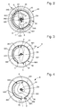
- the Figures 2 to 8 illustrate various non-limiting geometries of springs which are applicable to both the first spring 84 and the second spring 88.
- the figure 2 shows more particularly the first spring 84 housed in the first additional ratchet drive wheel 82, and the Figures 3 to 8 the second spring 88 housed in the second additional ratchet drive wheel 86.
- an outer turn 841, respectively 881, of the first spring 84, respectively of the second spring 88 cooperates with a housing 820, respectively 860, of the wheel 82, respectively 86, in which it is held by friction at its periphery or / and lugs 84A, respectively 88A that includes the first spring 84, respectively second spring 88.
- the inner part of each spring, 842, respectively 882 cooperates with the shaft 80, by a female portion 840, respectively 880, of the first spring 84, respectively of the second spring 88, of complementary profile to a male portion 800 of the shaft 80.
- the particular profile of the illustrated springs, with an asymmetrical stiffness of at least one arm 843, respectively 883, joining the inner part of each spring, 842, respectively 882, to its outer portion 841, respectively 881, makes it possible to apply a torque with a strong moment differential, depending on whether the relative pivoting movement between the shaft 80 and the respective wheel, is in one direction or the other.
- the ratio of the torque exerted in one direction with respect to the other is preferably greater than 3; depending on the shape of the spring, the sections used, and the pairs of materials present, this ratio can be notably increased, in particular beyond a factor of 10.
- each spring 842, respectively 882
- the profile of the spring is closed: the inner part of each spring, 842, respectively 882, has the shape of a rhombus centered on the shaft 80, one of the ends A of the rhombus constitutes the beginning of the outer portion 841, respectively 881, which is circular in almost a complete turn, before winding on itself at point C and forming an arm 843, respectively 883, in a circular sector of about a half-turn, radius less than that of the outer part, clinging to point B at the other end of the symmetrical rhombus at the first end A.
- the profile of the spring is open: the inner part, 842, respectively 882, has the shape of a disk extended on a radius by a triangle, whose distal tip E is the start of an arm 843, respectively 883, in circular sector of about a half-turn, before winding on itself at the point F and forming the outer portion 841, 881 respectively, which is circular in almost a complete turn, radius greater than that of the arm, before stopping at a distal end G.
- the profile of the spring is open: the inner part, 842, respectively 882, has the shape of a disk extended on a radius by a triangle, whose distal tip H constitutes the departure of an arm 843, respectively 883, in spiral increasing about half a turn to the point I where starts an outer portion 841, respectively 881, circular, before stopping at a distal end J, after about a turn and a quarter with respect to the point H.
- the profile of the spring is open, the spring having two symmetrical strands: the inner part, 842, respectively 882, has the shape of a disc which is hooked in K, N, an arm 843, respectively 883, spiraling increasing about three quarters of a turn to the point L, P, where starts an outer portion 841, respectively 881, circular one-half turn, before stopping at a distal end M, Q.
- the profile of the spring is closed, and comprises a mesh with a pitch of 120 °: the inner part, 842, respectively 882, has the shape of a disc whose part R at the point R an arm 843, respectively 883, substantially radial but curved, which joins at point S a rope 885 which joins two circular sectors of larger diameter, a sector TU forming an outer portion 841, respectively 881, the spring starting at point U on another rope 885 making about 120 ° with the previous one, and joining at point V another radial arc similar to the first one, the point V being the conjugate of the starting point S.
- the profile of the spring is open, the spring having two symmetrical strands: the inner part, 842, respectively 882, has the shape of a disk which is engaged in W a radial arm 886 of strong section, up to a point X of which part at right angle arm 843, respectively 883, of less section than the radial arm 886, to a distal end Y periphery of the wheel.
- Game-catching and blocking features are provided each time directly by a single component.
Landscapes
- Physics & Mathematics (AREA)
- General Physics & Mathematics (AREA)
- Gears, Cams (AREA)
- Springs (AREA)
- Mechanical Operated Clutches (AREA)
- Transmission Devices (AREA)
Abstract
Description
- L"invention concerne un mobile d'horlogerie à roue unidirectionnelle comportant un arbre porteur d'un pignon et d'au moins une première roue coaxiale avec ledit pignon et montée pivotante sur ledit arbre.
- L'invention concerne encore un mouvement d'horlogerie comportant au moins un tel mobile.
- L'invention concerne encore une pièce d'horlogerie comportant au moins un tel mouvement.
- L'invention concerne le domaine des mouvements mécaniques d'horlogerie.
- Il est souvent utile, dans un mécanisme d'horlogerie, de pouvoir commander un même mobile pivotant de façon à obtenir une réponse différente selon le sens de pivotement appliqué. Une telle fonction est en général exercée par un mécanisme à différentiel, encombrant et coûteux, surtout si ce mobile comporte plusieurs entrées.
- Le but de l'invention est de proposer un mobile d'horlogerie, à une ou plusieurs entrées, apportant une réponse différente en sortie selon le sens de pivotement qui lui est imposé par l'une ou l'autre des entrées.
- A cet effet, l'invention concerne un mobile d'horlogerie à roue unidirectionnelle comportant un arbre porteur d'un pignon et d'au moins une première roue coaxiale avec ledit pignon et montée pivotante sur ledit arbre, caractérisé en ce que ladite première roue est liée audit arbre par des premiers moyens de rappel élastique en rotation ou au moins un premier ressort constituant des premiers moyens de débrayage et qui exercent sur ladite première roue un effort de friction.
- Selon une caractéristique de l'invention, lesdits premiers moyens de débrayage exercent sur ladite première roue un effort de friction dont le moment du couple est différent selon le sens de pivotement relatif entre lesdits premiers moyens de débrayage et ladite première roue.
- Selon une caractéristique de l'invention, ledit mobile comporte encore une deuxième roue montée pivotante sur ledit arbre et liée audit arbre par des deuxièmes moyens de rappel élastique en rotation ou au moins un deuxième ressort constituant des deuxièmes moyens de débrayage et qui exercent sur ladite deuxième roue un effort de friction.
- Selon une caractéristique de l'invention, lesdits deuxièmes moyens de débrayage exercent sur ladite deuxième roue un effort de friction dont le moment du couple est différent selon le sens de pivotement relatif entre lesdits deuxièmes moyens de débrayage et ladite deuxième roue.
- Selon une caractéristique de l'invention, que ledit premier ressort est agencé pour générer un sens unidirectionnel de pivotement sans jeu de ladite première roue par rapport audit arbre dudit mobile, de façon à prévenir toute transmission d'un couple à un mobile antagoniste par une première denture que comporte ladite première roue lors de l'application d'un couple audit pignon.
- Selon une caractéristique de l'invention, ledit premier ressort est agencé pour générer un sens unidirectionnel de pivotement sans jeu de ladite première roue par rapport audit arbre dudit mobile, de façon à prévenir toute transmission d'un couple à un mobile antagoniste par ledit pignon lors de l'application d'un couple à une première denture que comporte ladite première roue.
- Selon une caractéristique de l'invention, ledit deuxième ressort est agencé pour générer un sens unidirectionnel de pivotement sans jeu de ladite deuxième roue par rapport audit arbre dudit mobile, de façon à prévenir toute transmission d'un couple à un mobile antagoniste par une deuxième denture que comporte ladite deuxième roue lors de l'application d'un couple audit pignon.
- Selon une caractéristique de l'invention, ledit deuxième ressort est agencé pour générer un sens unidirectionnel de pivotement sans jeu de ladite deuxième roue par rapport audit arbre dudit mobile, de façon à prévenir toute transmission d'un couple à un mobile antagoniste par ledit pignon lors de l'application d'un couple à une deuxième denture que comporte ladite deuxième roue .
- L'invention concerne encore un mouvement d'horlogerie comportant au moins un tel mobile, caractérisé en ce que ledit mouvement comporte au moins un mobile émetteur engrenant avec une denture d'une roue dudit mobile, et un mobile récepteur engrenant avec ledit pignon dudit mobile.
- Selon une caractéristique de l'invention, ledit mouvement comporte au moins un premier mobile émetteur engrenant avec une première denture d'une première roue dudit mobile et un deuxième mobile émetteur engrenant avec une deuxième denture d'une deuxième roue dudit mobile.
- L'invention concerne encore une pièce d'horlogerie comportant au moins un tel mouvement.
- D'autres caractéristiques et avantages de l'invention apparaîtront à la lecture de la description détaillée qui va suivre, en référence aux dessins annexés, où :
- la
figure 1 représente, de façon schématisée et en perspective, un mobile d'horlogerie à roue unidirectionnelle selon l'invention, comportant, de part et d'autre d'un arbre une première roue partiellement libre en pivotement liée par des moyens de rappel élastique à cet arbre, et une deuxième roue également partiellement libre en pivotement liée par des moyens de rappel élastique au même arbre ; - les
figures 2 à 8 représentent, de façon schématisée et en plan, différentes variantes des moyens de rappel élastique équipant la première roue ou/et la deuxième roue ; - la
figure 9 représente, de façon schématisée, partielle et en coupe, un mouvement d'horlogerie comportant un tel mobile ; - la
figure 10 représente, sous forme d'un schéma-blocs, une pièce d'horlogerie comportant un tel mouvement. - L'invention concerne un mobile d'horlogerie à roue unidirectionnelle 8 comportant un arbre 80 porteur d'un pignon 81 et d'au moins une première roue 82 coaxiale avec ce pignon 81 et montée pivotante sur cet arbre 80.
- Selon l'invention, cette première roue 82 est liée à l'arbre 80 par des premiers moyens de rappel élastique en rotation ou au moins un premier ressort 84 constituant des premiers moyens de débrayage 91, et qui exercent sur cette première roue 82 un effort de friction.
- Avantageusement ces premiers moyens de débrayage 91 exercent sur cette première roue 82 un effort de friction dont le moment du couple est différent selon le sens de pivotement relatif entre les premiers moyens de débrayage 91 et la première roue 82.
- Dans une réalisation avantageuse telle que présentée en
figure 1 , le mobile 8 comporte encore une deuxième roue 86 montée pivotante sur l'arbre 80, et qui est liée à cet arbre 80 par des deuxièmes moyens de rappel élastique en rotation ou au moins un deuxième ressort 88 constituant des deuxièmes moyens de débrayage 92, et qui exercent sur cette deuxième roue 86 un effort de friction. - Avantageusement ces deuxièmes moyens de débrayage 92 exercent sur cette deuxième roue 86 un effort de friction dont le moment du couple est différent selon le sens de pivotement relatif entre les deuxièmes moyens de débrayage 92 et la deuxième roue 86.
- Dans une réalisation particulière, le premier ressort 84 est agencé pour générer un sens unidirectionnel de pivotement sans jeu de la première roue 82 par rapport à l'arbre 80 du mobile 8, de façon à prévenir toute transmission d'un couple à un mobile antagoniste par une première denture 85 que comporte la première roue 82 lors de l'application d'un couple au pignon 81.
- Dans une réalisation particulière, le premier ressort 84 est agencé pour générer un sens unidirectionnel de pivotement sans jeu de la première roue 82 par rapport à l'arbre 80 du mobile 8, de façon à prévenir toute transmission d'un couple à un mobile antagoniste par le pignon 81 lors de l'application d'un couple à une première denture 85 que comporte la première roue 82.
- Dans une réalisation particulière, le deuxième ressort 88 est agencé pour générer un sens unidirectionnel de pivotement sans jeu de la deuxième roue 86 par rapport à l'arbre 80 du mobile 8, de façon à prévenir toute transmission d'un couple à un mobile antagoniste par une deuxième denture 89 que comporte la deuxième roue 86 lors de l'application d'un couple au pignon 81.
- Dans une réalisation particulière, le deuxième ressort 88 est agencé pour générer un sens unidirectionnel de pivotement sans jeu de la deuxième roue 86 par rapport à l'arbre 80 du mobile 8, de façon à prévenir toute transmission d'un couple à un mobile antagoniste par le pignon 81 lors de l'application d'un couple à une deuxième denture 89 que comporte la deuxième roue 86.
- Dans une réalisation particulière, la première roue 82 et la deuxième roue 86 sont unidirectionnelles dans le même sens de pivotement.
- Dans une réalisation particulière, la première roue 82 comporte une première denture 85 qui est différente d'une deuxième denture 89 que comporte lad deuxième roue 86.
- Dans une réalisation particulière, le premier ressort 84 est identique au deuxième ressort 88.
- L'invention concerne encore un mouvement d'horlogerie 100 comportant au moins un tel mobile 8. Selon l'invention ce mouvement 100 comporte au moins un mobile émetteur 1, 2, engrenant avec une denture 85, 89, d'une roue 82,86, de ce mobile 8, et un mobile récepteur 3 engrenant avec le pignon 81 du mobile 8.
- Dans une réalisation particulière, le mouvement 100 comporte au moins un premier mobile émetteur 1 engrenant avec une première denture 85 d'une première roue 82 dudit mobile 8 et un deuxième mobile émetteur 2 engrenant avec une deuxième denture 89 d'une deuxième roue 86 du mobile 8.
- L'invention concerne encore une pièce d'horlogerie 200, notamment une montre, comportant au moins un tel mouvement 100.
- Ainsi, des moyens de débrayage 9, constitués par les premiers moyens de rappel élastique en rotation ou par le au moins un premier ressort 84, exercent sur la première roue 82 un effort de friction, dont le moment du couple est différent selon le sens de pivotement relatif entre ces moyens de débrayage 9, et la première roue 82.
- La
figure 1 montre une réalisation particulière, non limitative, d'un mobile 8 monté, composé de cinq pièces: un axe 80, de préférence décolleté en acier 20AP standard, la première roue 82 et la deuxième roue 86, qui pivotent librement, et le premier ressort 84 et le deuxième ressort 88 qui garantissent l'entraînement ou non-entraînement de ces roues. - En ce qui concerne la première roue 82 et la deuxième roue 86 unidirectionnelles, fabriquées de préférence en Cuivre-Béryllium durci (CuBe), leur fonction est d'entraîner l'axe 80 lorsqu'elles subissent un couple d'origine externe.
- Par contre, elles ne doivent pas transmettre de couple lorsqu'elles sont entraînées par l'axe 80 (système de débrayage entre les deux roues). De plus, la roue 82 ou 86 ne doit pas avoir d'angle mort, au contraire d'une roue cliquet par exemple. De plus, les dentures 85 et 89 de ces roues 82 et 86 sont optimisées pour minimiser le jeu d'engrenage. Le comportement très différent de chaque ressort 84, 88, selon le sens du couple qui lui est appliqué peut être simplifié en un premier sens « libre » et un deuxième sens « friction » d'entraînement. Toutefois, même dans le sens dit libre du ressort, il existe un petit frottement entre le ressort et la roue concernée, du fait d'une légère précontrainte appliquée au ressort sur son diamètre extérieur, ce qui implique que la roue sera entraînée par ce faible couple de frottement, et tournera jusqu'à venir rattraper le jeu avec la roue ou le pignon suivant.
- Les deux roues 82 et 86 sont de préférence conçues pour recevoir le même ressort, ce qui limite le nombre de composants. De plus, leurs diamètres de pivotement sont de préférence identiques. Cela permet d'avoir la même dimension pour l'attache du ressort au centre sur l'entraînement, notamment six pans, de l'axe 80.
- Le premier 84 ou deuxième 88 ressort flexible a pour fonction d'entraîner l'axe 80 lorsqu'il travaille en sens bloquant. Dans le cas où l'axe 80 entraîne un ressort, il ne devrait pas entraîner la roue correspondante. De préférence, on minimise le couple de frottement et on maximise le couple de blocage.
- On comprend qu'un tel système de débrayage est indispensable pour éviter un retour de force intempestif par un rouage. Le mobile 8 forme une roue unidirectionnelle dont le fonctionnement ressemble à une roue cliquet d'inversion. Le mobile 8 représente un gros progrès par rapport aux inverseurs connus, car il est beaucoup moins volumineux, et donc plus facile à implanter dans un mouvement 100. Le mobile 8 selon l'invention n'a pas d'angle mort, ce qui autorise son montage dans un mouvement automatique.
- Les
figures 2 à 8 illustrent différentes géométries, non limitatives, de ressorts, qui sont applicables aussi bien au premier ressort 84 qu'au deuxième ressort 88. Lafigure 2 montre plus particulièrement le premier ressort 84 logé dans la première roue d'entraînement de rochet supplémentaire 82, et lesfigures 3 à 8 le deuxième ressort 88 logé dans la deuxième roue d'entraînement de rochet supplémentaire 86. Leur fixation à la roue correspondante est basée sur une friction: une spire externe 841, respectivement 881, du premier ressort 84, respectivement du deuxième ressort 88, coopère avec un logement 820, respectivement 860, de la roue 82, respectivement 86, dans laquelle elle est maintenue par friction au niveau de sa périphérie ou/et d'ergots 84A, respectivement 88A que comporte le premier ressort 84, respectivement deuxième ressort 88. La partie intérieure de chaque ressort, 842, respectivement 882, coopère avec l'arbre 80, par une partie femelle 840, respectivement 880, du premier ressort 84, respectivement du deuxième ressort 88, de profil complémentaire à une partie mâle 800 de l'arbre 80. - Le profil particulier des ressorts illustrés, avec une raideur asymétrique d'au moins un bras 843, respectivement 883, joignant la partie intérieure de chaque ressort, 842, respectivement 882, à sa partie externe 841, respectivement 881, permet d'appliquer un couple avec un fort différentiel de moment, selon que le mouvement de pivotement relatif entre l'arbre 80 et la roue respective, se fait dans un sens ou dans l'autre. Le rapport du couple exercé dans un sens par rapport à l'autre est de préférence supérieur à 3 ; selon la forme du ressort, les sections utilisées, et les couples de matériaux en présence, ce rapport peut être notablement augmenté, en particulier au-delà d'un facteur 10.
- Sur les
figures 2 et 3 , le profil du ressort est fermé : la partie intérieure de chaque ressort, 842, respectivement 882, a la forme d'un losange centré sur l'arbre 80, une des extrémités A du losange constitue le début de la partie externe 841, respectivement 881, laquelle est circulaire selon presque un tour complet, avant de s'enrouler sur elle-même au point C et d'y former un bras 843, respectivement 883, en secteur circulaire d'environ un demi-tour, de rayon inférieur à celui de la partie externe, s'accrochant au point B à l'autre extrémité du losange symétrique à la première extrémité A. - Sur la
figure 4 , le profil du ressort est ouvert : la partie intérieure, 842, respectivement 882, a la forme d'un disque prolongé sur un rayon par un triangle, dont la pointe distale E constitue le départ d'un bras 843, respectivement 883, en secteur circulaire d'environ un demi-tour, avant de s'enrouler sur elle-même au point F et d'y former la partie externe 841, respectivement 881, laquelle est circulaire selon presque un tour complet, de rayon supérieur à celui du bras, avant de s'arrêter à une extrémité distale G. - Sur la
figure 5 , le profil du ressort est ouvert : la partie intérieure, 842, respectivement 882, a la forme d'un disque prolongé sur un rayon par un triangle, dont la pointe distale H constitue le départ d'un bras 843, respectivement 883, en spirale croissante sur environ un demi-tour jusqu'au point I où démarre une partie externe 841, respectivement 881, circulaire, avant de s'arrêter à une extrémité distale J, après environ un tour et quart par rapport au point H. - Sur la
figure 6 , le profil du ressort est ouvert, le ressort comportant deux brins symétriques : la partie intérieure, 842, respectivement 882, a la forme d'un disque auquel s'accroche en K, N, un bras 843, respectivement 883, en spirale croissante sur environ trois quarts de tour jusqu'au point L, P, où démarre une partie externe 841, respectivement 881, circulaire d'un demi-tour, avant de s'arrêter à une extrémité distale M, Q. - Sur la
figure 7 , le profil du ressort est fermé, et comporte un maillage avec un pas de 120°: la partie intérieure, 842, respectivement 882, a la forme d'un disque dont part au point R un bras 843, respectivement 883, sensiblement radial mais incurvé, lequel rejoint au point S une corde 885 qui joint deux secteurs circulaires de plus grand diamètre, dont un secteur TU formant une partie externe 841, respectivement 881, le ressort repartant au point U sur une autre corde 885 faisant environ 120° avec la précédente, et rejoignant au point V un autre arc incurvé radial similaire au premier, le point V étant le conjugué du point S de départ. - Sur la
figure 8 , le profil du ressort est ouvert, le ressort comportant deux brins symétriques : la partie intérieure, 842, respectivement 882, a la forme d'un disque auquel s'accroche en W un bras radial 886 de forte section, jusqu'à un point X dont part à l'équerre un bras 843, respectivement 883, de moindre section que le bras radial 886, jusqu'à une extrémité distale Y en périphérie de la roue. - Ces ressorts des
figures 2 à 8 peuvent être réalisée par étampage, ou, pour ceux qui comportent des brins très fins, dans une fabrication « LIGA », « DRIE » ou similaire. - Le mécanisme selon l'invention répond bien aux critères suivants:
- sécurité du système lors du fonctionnement ;
- simplicité de réalisation et d'implémentation dans un mouvement existant ;
- fiabilité du système à la fois pour mouvement manuel et automatique ;
- efficacité optimale de réinjection d'énergie en diminuant au maximum les pertes ;
- limitation du nombre de composants et de leur complexité.
- Les fonctionnalités de rattrapage de jeu et de blocage sont assurées à chaque fois directement par un composant unique.
Claims (14)
- Mobile d'horlogerie à roue unidirectionnelle (8) comportant un arbre (80) porteur d'un pignon (81) et d'au moins une première roue (82) coaxiale avec ledit pignon (81) et montée pivotante sur ledit arbre (80), caractérisé en ce que ladite première roue (82) est liée audit arbre (80) par des premiers moyens de rappel élastique en rotation ou au moins un premier ressort (84) constituant des premiers moyens de débrayage (91) et qui exercent sur ladite première roue (82) un effort de friction.
- Mobile (8) selon la revendication 1, caractérisé en ce que lesdits premiers moyens de débrayage (91) exercent sur ladite première roue (82) un effort de friction dont le moment du couple est différent selon le sens de pivotement relatif entre lesdits premiers moyens de débrayage (91) et ladite première roue (82).
- Mobile (8) selon la revendication 1 ou 2, caractérisé en ce qu'il comporte encore une deuxième roue (86) montée pivotante sur ledit arbre (80) et liée audit arbre (80) par des deuxièmes moyens de rappel élastique en rotation ou au moins un deuxième ressort (88) constituant des deuxièmes moyens de débrayage (92) et qui exercent sur ladite deuxième roue (86) un effort de friction.
- Mobile (8) selon la revendication 3, caractérisé en ce que lesdits deuxièmes moyens de débrayage (92) exercent sur ladite deuxième roue (86) un effort de friction dont le moment du couple est différent selon le sens de pivotement relatif entre lesdits deuxièmes moyens de débrayage (92) et ladite deuxième roue (86).
- Mobile (8) selon l'une des revendications 1 à 4, caractérisé en ce que ledit premier ressort (84) est agencé pour générer un sens unidirectionnel de pivotement sans jeu de ladite première roue (82) par rapport audit arbre (80) dudit mobile (8), de façon à prévenir toute transmission d'un couple à un mobile antagoniste par une première denture (85) que comporte ladite première roue (82) lors de l'application d'un couple audit pignon (81).
- Mobile (8) selon l'une des revendications 1 à 5, caractérisé en ce que ledit premier ressort (84) est agencé pour générer un sens unidirectionnel de pivotement sans jeu de ladite première roue (82) par rapport audit arbre (80) dudit mobile (8), de façon à prévenir toute transmission d'un couple à un mobile antagoniste par ledit pignon (81) lors de l'application d'un couple à une première denture (85) que comporte ladite première roue (82).
- Mobile (8) selon la revendication 3 ou 4, caractérisé en ce que ledit deuxième ressort (88) est agencé pour générer un sens unidirectionnel de pivotement sans jeu de ladite deuxième roue (86) par rapport audit arbre (80) dudit mobile (8), de façon à prévenir toute transmission d'un couple à un mobile antagoniste par une deuxième denture (89) que comporte ladite deuxième roue (86) lors de l'application d'un couple audit pignon (81).
- Mobile (8) selon la revendication 3 ou 4, caractérisé en ce que ledit deuxième ressort (88) est agencé pour générer un sens unidirectionnel de pivotement sans jeu de ladite deuxième roue (86) par rapport audit arbre (80) dudit mobile (8), de façon à prévenir toute transmission d'un couple à un mobile antagoniste par ledit pignon (81) lors de l'application d'un couple à une deuxième denture (89) que comporte ladite deuxième roue (86).
- Mobile (8) selon la revendication 3 ou 4, caractérisé en ce que ladite première roue (82) et ladite deuxième roue (86) sont unidirectionnelles dans le même sens de pivotement.
- Mobile (8) selon la revendication 3 ou 4 caractérisé en ce que ladite première roue (82) comporte une première denture (85) qui est différente d'une deuxième denture (89) que comporte ladite deuxième roue (86).
- Mobile (8) selon la revendication 9 ou 10, caractérisé en ce que ledit premier ressort (84) est identique audit deuxième ressort (88).
- Mouvement d'horlogerie (100) comportant au moins un mobile (8) selon l'une des revendications précédentes, caractérisé en ce que ledit mouvement (100) comporte au moins un mobile émetteur (1; 2) engrenant avec une denture (85 ; 89) d'une roue (82; 86) dudit mobile (8), et un mobile récepteur (3) engrenant avec ledit pignon (81) dudit mobile (8).
- Mouvement d'horlogerie (100) selon les revendications 3 et 12, caractérisé en ce que ledit mouvement (100) comporte au moins un premier mobile émetteur (1) engrenant avec une première denture (85) d'une première roue (82) dudit mobile (8) et un deuxième mobile émetteur (2) engrenant avec une deuxième denture (89) d'une deuxième roue (86) dudit mobile (8).
- Pièce d'horlogerie (200) comportant au moins un mouvement (100) selon l'une des revendications 12 ou 13.
Priority Applications (6)
| Application Number | Priority Date | Filing Date | Title |
|---|---|---|---|
| EP13191782.5A EP2871534B1 (fr) | 2013-11-06 | 2013-11-06 | Mobile d'horlogerie à roues unidirectionnelles |
| US14/516,033 US9298163B2 (en) | 2013-11-06 | 2014-10-16 | Timepiece wheel set with a unidirectional wheel |
| JP2014222325A JP5883910B2 (ja) | 2013-11-06 | 2014-10-31 | 単方向歯車を有する時計用ホイールセット |
| CN201420674500.9U CN204229119U (zh) | 2013-11-06 | 2014-11-06 | 具有单向轮的钟表轮副、钟表机芯和钟表 |
| CN201410641785.0A CN104635467B (zh) | 2013-11-06 | 2014-11-06 | 具有单向轮的钟表轮副 |
| HK15109564.0A HK1208916B (en) | 2013-11-06 | 2015-09-29 | Timepiece wheel set with a unidirectional wheel |
Applications Claiming Priority (1)
| Application Number | Priority Date | Filing Date | Title |
|---|---|---|---|
| EP13191782.5A EP2871534B1 (fr) | 2013-11-06 | 2013-11-06 | Mobile d'horlogerie à roues unidirectionnelles |
Publications (2)
| Publication Number | Publication Date |
|---|---|
| EP2871534A1 true EP2871534A1 (fr) | 2015-05-13 |
| EP2871534B1 EP2871534B1 (fr) | 2017-01-04 |
Family
ID=49517437
Family Applications (1)
| Application Number | Title | Priority Date | Filing Date |
|---|---|---|---|
| EP13191782.5A Active EP2871534B1 (fr) | 2013-11-06 | 2013-11-06 | Mobile d'horlogerie à roues unidirectionnelles |
Country Status (4)
| Country | Link |
|---|---|
| US (1) | US9298163B2 (fr) |
| EP (1) | EP2871534B1 (fr) |
| JP (1) | JP5883910B2 (fr) |
| CN (2) | CN204229119U (fr) |
Cited By (3)
| Publication number | Priority date | Publication date | Assignee | Title |
|---|---|---|---|---|
| EP3489761A1 (fr) | 2017-11-24 | 2019-05-29 | Blancpain SA | Mobile d'horlogerie a roue unidirectionnelle |
| EP3705949A1 (fr) * | 2019-03-05 | 2020-09-09 | ETA SA Manufacture Horlogère Suisse | Mecanisme limiteur de couple d'horlogerie |
| EP4170434B1 (fr) * | 2021-10-25 | 2025-10-01 | Comadur SA | Procede de decoration d'un substrat |
Families Citing this family (6)
| Publication number | Priority date | Publication date | Assignee | Title |
|---|---|---|---|---|
| EP2871534B1 (fr) * | 2013-11-06 | 2017-01-04 | ETA SA Manufacture Horlogère Suisse | Mobile d'horlogerie à roues unidirectionnelles |
| EP3220206B1 (fr) * | 2016-03-16 | 2020-09-30 | Rolex Sa | Dispositif horloger de transmission |
| EP3273303B1 (fr) * | 2016-07-19 | 2025-10-01 | Nivarox-FAR S.A. | Pièce pour mouvement d'horlogerie |
| EP3580618B1 (fr) * | 2017-02-13 | 2022-01-26 | Patek Philippe SA Genève | Organe moteur d'horlogerie |
| EP3418816B1 (fr) * | 2017-06-20 | 2019-10-16 | Lakeview Innovation Ltd. | Balancier spiral comprenant une section transversale en forme de losange pour un mécanisme d'horlogerie d'un mouvement de montre et procédé de fabrication du balancier spiral |
| EP3543798B1 (fr) * | 2018-03-20 | 2020-12-30 | Omega SA | Systeme de lunette tournante annulaire comprenant au moins un bras elastique |
Citations (3)
| Publication number | Priority date | Publication date | Assignee | Title |
|---|---|---|---|---|
| EP1429213A2 (fr) * | 2002-12-11 | 2004-06-16 | Frank Müller Watchland S.A. | Dispositif destiné à permettre une rotation dans un sens et de l'exclure dans le sens contraire |
| EP2085832A1 (fr) * | 2008-02-04 | 2009-08-05 | Frédéric Piguet S.A. | Dispositif de chronographe avec embrayage à friction |
| CH702924B1 (fr) * | 2010-06-03 | 2011-10-14 | Patek Philippe Sa Geneve | Mobile à embrayage unidirectionnel, mécanisme de remontage et pièce d'horlogerie comportant ledit mobile. |
Family Cites Families (15)
| Publication number | Priority date | Publication date | Assignee | Title |
|---|---|---|---|---|
| CH300077A (fr) * | 1951-12-15 | 1954-07-15 | Bulova Watch Co Inc | Montre à remontage automatique par les mouvements dans les deux sens d'une masse oscillante. |
| CH223773A4 (fr) * | 1973-02-16 | 1975-01-31 | ||
| JPS54170870U (fr) * | 1978-05-22 | 1979-12-03 | ||
| CH681191B5 (fr) * | 1991-09-11 | 1993-08-13 | Ebauchesfabrik Eta Ag | |
| CH682967B5 (fr) * | 1991-10-17 | 1994-06-30 | Bulgari Gianni Spa | Dispositif d'affichage pour pièce d'horlogerie. |
| JPH11174169A (ja) * | 1997-12-10 | 1999-07-02 | Seiko Instruments Inc | 時クロノグラフの発停構造およびスリップ用バネ |
| CH697381B1 (fr) * | 2003-03-12 | 2008-09-15 | Pierre Kunz S A | Mécanisme comprenant un premier mobile en contact ou destiné à venir en contact avec un deuxième élément. |
| CH699838B1 (fr) * | 2004-03-09 | 2010-05-14 | Franck Muller Watchland Sa | Tourbillon tri-axial pour pièce d'horlogerie, notamment montre-bracelet. |
| EP1586960A1 (fr) | 2004-04-14 | 2005-10-19 | Meco S.A. | Couronne pour pièce d'horlogerie avec dispositif de débrayage |
| JP2006071503A (ja) * | 2004-09-02 | 2006-03-16 | Seiko Epson Corp | 時計用車および時計 |
| EP1843225B1 (fr) | 2006-04-07 | 2009-07-15 | ETA SA Manufacture Horlogère Suisse | Mécanisme inverseur pour entraînement rotatif unidirectionnel d'un mobile |
| DE602007006151D1 (de) * | 2007-02-14 | 2010-06-10 | Maurice Lacroix Sa | Mechanismus zur umschaltbaren Übertragung |
| DE602007007888D1 (de) * | 2007-04-04 | 2010-09-02 | Eta Sa Mft Horlogere Suisse | Aufzugsvorrichtung mit unidirektionale Kupplung |
| EP2339413B1 (fr) * | 2009-12-22 | 2012-09-12 | The Swatch Group Research and Development Ltd. | Mouvement d'horlogerie muni d'une alarme vibrante |
| EP2871534B1 (fr) * | 2013-11-06 | 2017-01-04 | ETA SA Manufacture Horlogère Suisse | Mobile d'horlogerie à roues unidirectionnelles |
-
2013
- 2013-11-06 EP EP13191782.5A patent/EP2871534B1/fr active Active
-
2014
- 2014-10-16 US US14/516,033 patent/US9298163B2/en active Active
- 2014-10-31 JP JP2014222325A patent/JP5883910B2/ja active Active
- 2014-11-06 CN CN201420674500.9U patent/CN204229119U/zh not_active Withdrawn - After Issue
- 2014-11-06 CN CN201410641785.0A patent/CN104635467B/zh active Active
Patent Citations (3)
| Publication number | Priority date | Publication date | Assignee | Title |
|---|---|---|---|---|
| EP1429213A2 (fr) * | 2002-12-11 | 2004-06-16 | Frank Müller Watchland S.A. | Dispositif destiné à permettre une rotation dans un sens et de l'exclure dans le sens contraire |
| EP2085832A1 (fr) * | 2008-02-04 | 2009-08-05 | Frédéric Piguet S.A. | Dispositif de chronographe avec embrayage à friction |
| CH702924B1 (fr) * | 2010-06-03 | 2011-10-14 | Patek Philippe Sa Geneve | Mobile à embrayage unidirectionnel, mécanisme de remontage et pièce d'horlogerie comportant ledit mobile. |
Cited By (5)
| Publication number | Priority date | Publication date | Assignee | Title |
|---|---|---|---|---|
| EP3489761A1 (fr) | 2017-11-24 | 2019-05-29 | Blancpain SA | Mobile d'horlogerie a roue unidirectionnelle |
| EP3705949A1 (fr) * | 2019-03-05 | 2020-09-09 | ETA SA Manufacture Horlogère Suisse | Mecanisme limiteur de couple d'horlogerie |
| US11768464B2 (en) | 2019-03-05 | 2023-09-26 | Eta Sa Manufacture Horlogere Suisse | Horological torque limiting mechanism |
| EP4170434B1 (fr) * | 2021-10-25 | 2025-10-01 | Comadur SA | Procede de decoration d'un substrat |
| US12461492B2 (en) | 2021-10-25 | 2025-11-04 | Comadur Sa | Method for decorating a substrate |
Also Published As
| Publication number | Publication date |
|---|---|
| CN104635467A (zh) | 2015-05-20 |
| JP2015090368A (ja) | 2015-05-11 |
| EP2871534B1 (fr) | 2017-01-04 |
| US9298163B2 (en) | 2016-03-29 |
| CN104635467B (zh) | 2017-11-24 |
| JP5883910B2 (ja) | 2016-03-15 |
| HK1208916A1 (en) | 2016-03-18 |
| US20150124569A1 (en) | 2015-05-07 |
| CN204229119U (zh) | 2015-03-25 |
Similar Documents
| Publication | Publication Date | Title |
|---|---|---|
| EP2871534A1 (fr) | Mobile d'horlogerie à roue unidirectionnelle | |
| EP2864167B1 (fr) | Servofrein electrique a compensation de jeu de transmission | |
| EP1918789A1 (fr) | Masse oscillante pour recharger la source d'énergie d'un instrument portable | |
| EP2871537A1 (fr) | Montre à réserve de marche améliorée | |
| FR2952689A1 (fr) | Differentiel a glissement limite avec dispositif de poussee dynamique | |
| EP4058853B1 (fr) | Mobile d'embrayage unidirectionnel, notamment pour l'horlogerie | |
| EP3365544A1 (fr) | Moteur thermique muni d'un système de variation du taux de compression | |
| CH708818A2 (fr) | Mobile d'horlogerie à roue unidirectionnelle. | |
| FR2856019A1 (fr) | Garniture d'articulation pour un dispositif de reglage d'un siege de vehicule automobile | |
| WO2015090977A1 (fr) | Dispositif a deux trains d'engrenages imbriques | |
| FR2801656A1 (fr) | Mecanisme a roue d'engrenage conique et systeme de direction a puissance electrique l'utilisant | |
| EP3376308B1 (fr) | Mécanisme de remontage d'une pièce d'horlogerie | |
| EP4339099A1 (fr) | Réducteur de vitesse pour un dispositif d'entraînement d'une roue d'un train d'atterrissage d'aéronef | |
| FR3016252A1 (fr) | Dispositif de transformation d'energie mecanique en energie electrique, notamment pour une eolienne | |
| EP2707615B1 (fr) | Couronne pour reducteur a train epicycloidal | |
| EP3376309B1 (fr) | Mécanisme de remontage d'une pièce d'horlogerie | |
| CH713407A2 (fr) | Système de remontage pour pièce d'horlogerie. | |
| EP3250842B1 (fr) | Amortisseur de torsion a ressorts droits | |
| EP4296788B1 (fr) | Dispositif de remontage automatique d'un ressort de barillet d'un mouvement horloger | |
| CA2925055A1 (fr) | Dispositif reducteur de vitesse angulaire | |
| FR3007099A1 (fr) | Reducteur epicycloidal pour actionneur d’enroulement et de deroulement | |
| CH713583B1 (fr) | Mécanisme de remontage d'une pièce d'horlogerie. | |
| FR2897136A1 (fr) | Boite de vitesse a transmission planetaire donnant jusqu'a onze vitesses de marche avant et deux vitesses de marche arriere. | |
| EP1216367A1 (fr) | Dispositif de reduction planetaire | |
| FR3136265A3 (fr) | Dispositif et procédé d’embrayage unidirectionnel |
Legal Events
| Date | Code | Title | Description |
|---|---|---|---|
| PUAI | Public reference made under article 153(3) epc to a published international application that has entered the european phase |
Free format text: ORIGINAL CODE: 0009012 |
|
| 17P | Request for examination filed |
Effective date: 20131106 |
|
| AK | Designated contracting states |
Kind code of ref document: A1 Designated state(s): AL AT BE BG CH CY CZ DE DK EE ES FI FR GB GR HR HU IE IS IT LI LT LU LV MC MK MT NL NO PL PT RO RS SE SI SK SM TR |
|
| AX | Request for extension of the european patent |
Extension state: BA ME |
|
| R17P | Request for examination filed (corrected) |
Effective date: 20150617 |
|
| RBV | Designated contracting states (corrected) |
Designated state(s): AL AT BE BG CH CY CZ DE DK EE ES FI FR GB GR HR HU IE IS IT LI LT LU LV MC MK MT NL NO PL PT RO RS SE SI SK SM TR |
|
| GRAP | Despatch of communication of intention to grant a patent |
Free format text: ORIGINAL CODE: EPIDOSNIGR1 |
|
| INTG | Intention to grant announced |
Effective date: 20160920 |
|
| GRAS | Grant fee paid |
Free format text: ORIGINAL CODE: EPIDOSNIGR3 |
|
| GRAA | (expected) grant |
Free format text: ORIGINAL CODE: 0009210 |
|
| AK | Designated contracting states |
Kind code of ref document: B1 Designated state(s): AL AT BE BG CH CY CZ DE DK EE ES FI FR GB GR HR HU IE IS IT LI LT LU LV MC MK MT NL NO PL PT RO RS SE SI SK SM TR |
|
| REG | Reference to a national code |
Ref country code: GB Ref legal event code: FG4D Free format text: NOT ENGLISH |
|
| REG | Reference to a national code |
Ref country code: CH Ref legal event code: EP |
|
| REG | Reference to a national code |
Ref country code: AT Ref legal event code: REF Ref document number: 859829 Country of ref document: AT Kind code of ref document: T Effective date: 20170115 |
|
| REG | Reference to a national code |
Ref country code: IE Ref legal event code: FG4D Free format text: LANGUAGE OF EP DOCUMENT: FRENCH |
|
| REG | Reference to a national code |
Ref country code: CH Ref legal event code: NV Representative=s name: ICB INGENIEURS CONSEILS EN BREVETS SA, CH |
|
| REG | Reference to a national code |
Ref country code: DE Ref legal event code: R096 Ref document number: 602013016105 Country of ref document: DE |
|
| REG | Reference to a national code |
Ref country code: LT Ref legal event code: MG4D Ref country code: NL Ref legal event code: MP Effective date: 20170104 |
|
| REG | Reference to a national code |
Ref country code: AT Ref legal event code: MK05 Ref document number: 859829 Country of ref document: AT Kind code of ref document: T Effective date: 20170104 |
|
| PG25 | Lapsed in a contracting state [announced via postgrant information from national office to epo] |
Ref country code: NL Free format text: LAPSE BECAUSE OF FAILURE TO SUBMIT A TRANSLATION OF THE DESCRIPTION OR TO PAY THE FEE WITHIN THE PRESCRIBED TIME-LIMIT Effective date: 20170104 |
|
| PG25 | Lapsed in a contracting state [announced via postgrant information from national office to epo] |
Ref country code: LT Free format text: LAPSE BECAUSE OF FAILURE TO SUBMIT A TRANSLATION OF THE DESCRIPTION OR TO PAY THE FEE WITHIN THE PRESCRIBED TIME-LIMIT Effective date: 20170104 Ref country code: HR Free format text: LAPSE BECAUSE OF FAILURE TO SUBMIT A TRANSLATION OF THE DESCRIPTION OR TO PAY THE FEE WITHIN THE PRESCRIBED TIME-LIMIT Effective date: 20170104 Ref country code: GR Free format text: LAPSE BECAUSE OF FAILURE TO SUBMIT A TRANSLATION OF THE DESCRIPTION OR TO PAY THE FEE WITHIN THE PRESCRIBED TIME-LIMIT Effective date: 20170405 Ref country code: FI Free format text: LAPSE BECAUSE OF FAILURE TO SUBMIT A TRANSLATION OF THE DESCRIPTION OR TO PAY THE FEE WITHIN THE PRESCRIBED TIME-LIMIT Effective date: 20170104 Ref country code: IS Free format text: LAPSE BECAUSE OF FAILURE TO SUBMIT A TRANSLATION OF THE DESCRIPTION OR TO PAY THE FEE WITHIN THE PRESCRIBED TIME-LIMIT Effective date: 20170504 Ref country code: NO Free format text: LAPSE BECAUSE OF FAILURE TO SUBMIT A TRANSLATION OF THE DESCRIPTION OR TO PAY THE FEE WITHIN THE PRESCRIBED TIME-LIMIT Effective date: 20170404 |
|
| PG25 | Lapsed in a contracting state [announced via postgrant information from national office to epo] |
Ref country code: RS Free format text: LAPSE BECAUSE OF FAILURE TO SUBMIT A TRANSLATION OF THE DESCRIPTION OR TO PAY THE FEE WITHIN THE PRESCRIBED TIME-LIMIT Effective date: 20170104 Ref country code: LV Free format text: LAPSE BECAUSE OF FAILURE TO SUBMIT A TRANSLATION OF THE DESCRIPTION OR TO PAY THE FEE WITHIN THE PRESCRIBED TIME-LIMIT Effective date: 20170104 Ref country code: AT Free format text: LAPSE BECAUSE OF FAILURE TO SUBMIT A TRANSLATION OF THE DESCRIPTION OR TO PAY THE FEE WITHIN THE PRESCRIBED TIME-LIMIT Effective date: 20170104 Ref country code: PT Free format text: LAPSE BECAUSE OF FAILURE TO SUBMIT A TRANSLATION OF THE DESCRIPTION OR TO PAY THE FEE WITHIN THE PRESCRIBED TIME-LIMIT Effective date: 20170504 Ref country code: PL Free format text: LAPSE BECAUSE OF FAILURE TO SUBMIT A TRANSLATION OF THE DESCRIPTION OR TO PAY THE FEE WITHIN THE PRESCRIBED TIME-LIMIT Effective date: 20170104 Ref country code: ES Free format text: LAPSE BECAUSE OF FAILURE TO SUBMIT A TRANSLATION OF THE DESCRIPTION OR TO PAY THE FEE WITHIN THE PRESCRIBED TIME-LIMIT Effective date: 20170104 Ref country code: BG Free format text: LAPSE BECAUSE OF FAILURE TO SUBMIT A TRANSLATION OF THE DESCRIPTION OR TO PAY THE FEE WITHIN THE PRESCRIBED TIME-LIMIT Effective date: 20170404 Ref country code: SE Free format text: LAPSE BECAUSE OF FAILURE TO SUBMIT A TRANSLATION OF THE DESCRIPTION OR TO PAY THE FEE WITHIN THE PRESCRIBED TIME-LIMIT Effective date: 20170104 |
|
| REG | Reference to a national code |
Ref country code: DE Ref legal event code: R097 Ref document number: 602013016105 Country of ref document: DE |
|
| REG | Reference to a national code |
Ref country code: FR Ref legal event code: PLFP Year of fee payment: 5 |
|
| PG25 | Lapsed in a contracting state [announced via postgrant information from national office to epo] |
Ref country code: IT Free format text: LAPSE BECAUSE OF FAILURE TO SUBMIT A TRANSLATION OF THE DESCRIPTION OR TO PAY THE FEE WITHIN THE PRESCRIBED TIME-LIMIT Effective date: 20170104 Ref country code: EE Free format text: LAPSE BECAUSE OF FAILURE TO SUBMIT A TRANSLATION OF THE DESCRIPTION OR TO PAY THE FEE WITHIN THE PRESCRIBED TIME-LIMIT Effective date: 20170104 Ref country code: CZ Free format text: LAPSE BECAUSE OF FAILURE TO SUBMIT A TRANSLATION OF THE DESCRIPTION OR TO PAY THE FEE WITHIN THE PRESCRIBED TIME-LIMIT Effective date: 20170104 Ref country code: RO Free format text: LAPSE BECAUSE OF FAILURE TO SUBMIT A TRANSLATION OF THE DESCRIPTION OR TO PAY THE FEE WITHIN THE PRESCRIBED TIME-LIMIT Effective date: 20170104 Ref country code: SK Free format text: LAPSE BECAUSE OF FAILURE TO SUBMIT A TRANSLATION OF THE DESCRIPTION OR TO PAY THE FEE WITHIN THE PRESCRIBED TIME-LIMIT Effective date: 20170104 |
|
| PLBE | No opposition filed within time limit |
Free format text: ORIGINAL CODE: 0009261 |
|
| STAA | Information on the status of an ep patent application or granted ep patent |
Free format text: STATUS: NO OPPOSITION FILED WITHIN TIME LIMIT |
|
| PG25 | Lapsed in a contracting state [announced via postgrant information from national office to epo] |
Ref country code: SM Free format text: LAPSE BECAUSE OF FAILURE TO SUBMIT A TRANSLATION OF THE DESCRIPTION OR TO PAY THE FEE WITHIN THE PRESCRIBED TIME-LIMIT Effective date: 20170104 Ref country code: DK Free format text: LAPSE BECAUSE OF FAILURE TO SUBMIT A TRANSLATION OF THE DESCRIPTION OR TO PAY THE FEE WITHIN THE PRESCRIBED TIME-LIMIT Effective date: 20170104 |
|
| 26N | No opposition filed |
Effective date: 20171005 |
|
| PG25 | Lapsed in a contracting state [announced via postgrant information from national office to epo] |
Ref country code: SI Free format text: LAPSE BECAUSE OF FAILURE TO SUBMIT A TRANSLATION OF THE DESCRIPTION OR TO PAY THE FEE WITHIN THE PRESCRIBED TIME-LIMIT Effective date: 20170104 |
|
| PG25 | Lapsed in a contracting state [announced via postgrant information from national office to epo] |
Ref country code: MC Free format text: LAPSE BECAUSE OF FAILURE TO SUBMIT A TRANSLATION OF THE DESCRIPTION OR TO PAY THE FEE WITHIN THE PRESCRIBED TIME-LIMIT Effective date: 20170104 |
|
| GBPC | Gb: european patent ceased through non-payment of renewal fee |
Effective date: 20171106 |
|
| PG25 | Lapsed in a contracting state [announced via postgrant information from national office to epo] |
Ref country code: LU Free format text: LAPSE BECAUSE OF NON-PAYMENT OF DUE FEES Effective date: 20171106 |
|
| REG | Reference to a national code |
Ref country code: BE Ref legal event code: MM Effective date: 20171130 |
|
| REG | Reference to a national code |
Ref country code: IE Ref legal event code: MM4A |
|
| PG25 | Lapsed in a contracting state [announced via postgrant information from national office to epo] |
Ref country code: MT Free format text: LAPSE BECAUSE OF FAILURE TO SUBMIT A TRANSLATION OF THE DESCRIPTION OR TO PAY THE FEE WITHIN THE PRESCRIBED TIME-LIMIT Effective date: 20170104 |
|
| REG | Reference to a national code |
Ref country code: FR Ref legal event code: PLFP Year of fee payment: 6 |
|
| PG25 | Lapsed in a contracting state [announced via postgrant information from national office to epo] |
Ref country code: IE Free format text: LAPSE BECAUSE OF NON-PAYMENT OF DUE FEES Effective date: 20171106 |
|
| PG25 | Lapsed in a contracting state [announced via postgrant information from national office to epo] |
Ref country code: BE Free format text: LAPSE BECAUSE OF NON-PAYMENT OF DUE FEES Effective date: 20171130 Ref country code: GB Free format text: LAPSE BECAUSE OF NON-PAYMENT OF DUE FEES Effective date: 20171106 |
|
| PG25 | Lapsed in a contracting state [announced via postgrant information from national office to epo] |
Ref country code: HU Free format text: LAPSE BECAUSE OF FAILURE TO SUBMIT A TRANSLATION OF THE DESCRIPTION OR TO PAY THE FEE WITHIN THE PRESCRIBED TIME-LIMIT; INVALID AB INITIO Effective date: 20131106 |
|
| PG25 | Lapsed in a contracting state [announced via postgrant information from national office to epo] |
Ref country code: CY Free format text: LAPSE BECAUSE OF FAILURE TO SUBMIT A TRANSLATION OF THE DESCRIPTION OR TO PAY THE FEE WITHIN THE PRESCRIBED TIME-LIMIT Effective date: 20170104 |
|
| PG25 | Lapsed in a contracting state [announced via postgrant information from national office to epo] |
Ref country code: MK Free format text: LAPSE BECAUSE OF FAILURE TO SUBMIT A TRANSLATION OF THE DESCRIPTION OR TO PAY THE FEE WITHIN THE PRESCRIBED TIME-LIMIT Effective date: 20170104 |
|
| PG25 | Lapsed in a contracting state [announced via postgrant information from national office to epo] |
Ref country code: TR Free format text: LAPSE BECAUSE OF FAILURE TO SUBMIT A TRANSLATION OF THE DESCRIPTION OR TO PAY THE FEE WITHIN THE PRESCRIBED TIME-LIMIT Effective date: 20170104 |
|
| PG25 | Lapsed in a contracting state [announced via postgrant information from national office to epo] |
Ref country code: AL Free format text: LAPSE BECAUSE OF FAILURE TO SUBMIT A TRANSLATION OF THE DESCRIPTION OR TO PAY THE FEE WITHIN THE PRESCRIBED TIME-LIMIT Effective date: 20170104 |
|
| P01 | Opt-out of the competence of the unified patent court (upc) registered |
Effective date: 20230701 |
|
| REG | Reference to a national code |
Ref country code: CH Ref legal event code: U11 Free format text: ST27 STATUS EVENT CODE: U-0-0-U10-U11 (AS PROVIDED BY THE NATIONAL OFFICE) Effective date: 20251201 |
|
| PGFP | Annual fee paid to national office [announced via postgrant information from national office to epo] |
Ref country code: DE Payment date: 20251022 Year of fee payment: 13 |
|
| PGFP | Annual fee paid to national office [announced via postgrant information from national office to epo] |
Ref country code: FR Payment date: 20251023 Year of fee payment: 13 |
|
| PGFP | Annual fee paid to national office [announced via postgrant information from national office to epo] |
Ref country code: CH Payment date: 20251201 Year of fee payment: 13 |