EP2873821A1 - Exhaust gas aftertreatment device - Google Patents
Exhaust gas aftertreatment device Download PDFInfo
- Publication number
- EP2873821A1 EP2873821A1 EP20130193095 EP13193095A EP2873821A1 EP 2873821 A1 EP2873821 A1 EP 2873821A1 EP 20130193095 EP20130193095 EP 20130193095 EP 13193095 A EP13193095 A EP 13193095A EP 2873821 A1 EP2873821 A1 EP 2873821A1
- Authority
- EP
- European Patent Office
- Prior art keywords
- exhaust gas
- catalytic converter
- volume
- guiding means
- aftertreatment device
- Prior art date
- Legal status (The legal status is an assumption and is not a legal conclusion. Google has not performed a legal analysis and makes no representation as to the accuracy of the status listed.)
- Granted
Links
Images

Classifications
-
- F—MECHANICAL ENGINEERING; LIGHTING; HEATING; WEAPONS; BLASTING
- F01—MACHINES OR ENGINES IN GENERAL; ENGINE PLANTS IN GENERAL; STEAM ENGINES
- F01N—GAS-FLOW SILENCERS OR EXHAUST APPARATUS FOR MACHINES OR ENGINES IN GENERAL; GAS-FLOW SILENCERS OR EXHAUST APPARATUS FOR INTERNAL-COMBUSTION ENGINES
- F01N3/00—Exhaust or silencing apparatus having means for purifying, rendering innocuous, or otherwise treating exhaust
- F01N3/08—Exhaust or silencing apparatus having means for purifying, rendering innocuous, or otherwise treating exhaust for rendering innocuous
- F01N3/10—Exhaust or silencing apparatus having means for purifying, rendering innocuous, or otherwise treating exhaust for rendering innocuous by thermal or catalytic conversion of noxious components of exhaust
- F01N3/18—Exhaust or silencing apparatus having means for purifying, rendering innocuous, or otherwise treating exhaust for rendering innocuous by thermal or catalytic conversion of noxious components of exhaust characterised by methods of operation; Control
- F01N3/20—Exhaust or silencing apparatus having means for purifying, rendering innocuous, or otherwise treating exhaust for rendering innocuous by thermal or catalytic conversion of noxious components of exhaust characterised by methods of operation; Control specially adapted for catalytic conversion
- F01N3/206—Adding periodically or continuously substances to exhaust gases for promoting purification, e.g. catalytic material in liquid form, NOx reducing agents
- F01N3/2066—Selective catalytic reduction [SCR]
-
- F—MECHANICAL ENGINEERING; LIGHTING; HEATING; WEAPONS; BLASTING
- F01—MACHINES OR ENGINES IN GENERAL; ENGINE PLANTS IN GENERAL; STEAM ENGINES
- F01N—GAS-FLOW SILENCERS OR EXHAUST APPARATUS FOR MACHINES OR ENGINES IN GENERAL; GAS-FLOW SILENCERS OR EXHAUST APPARATUS FOR INTERNAL-COMBUSTION ENGINES
- F01N13/00—Exhaust or silencing apparatus characterised by constructional features
- F01N13/009—Exhaust or silencing apparatus characterised by constructional features having two or more separate purifying devices arranged in series
- F01N13/0097—Exhaust or silencing apparatus characterised by constructional features having two or more separate purifying devices arranged in series the purifying devices are arranged in a single housing
-
- F—MECHANICAL ENGINEERING; LIGHTING; HEATING; WEAPONS; BLASTING
- F01—MACHINES OR ENGINES IN GENERAL; ENGINE PLANTS IN GENERAL; STEAM ENGINES
- F01N—GAS-FLOW SILENCERS OR EXHAUST APPARATUS FOR MACHINES OR ENGINES IN GENERAL; GAS-FLOW SILENCERS OR EXHAUST APPARATUS FOR INTERNAL-COMBUSTION ENGINES
- F01N3/00—Exhaust or silencing apparatus having means for purifying, rendering innocuous, or otherwise treating exhaust
- F01N3/08—Exhaust or silencing apparatus having means for purifying, rendering innocuous, or otherwise treating exhaust for rendering innocuous
- F01N3/10—Exhaust or silencing apparatus having means for purifying, rendering innocuous, or otherwise treating exhaust for rendering innocuous by thermal or catalytic conversion of noxious components of exhaust
-
- F—MECHANICAL ENGINEERING; LIGHTING; HEATING; WEAPONS; BLASTING
- F01—MACHINES OR ENGINES IN GENERAL; ENGINE PLANTS IN GENERAL; STEAM ENGINES
- F01N—GAS-FLOW SILENCERS OR EXHAUST APPARATUS FOR MACHINES OR ENGINES IN GENERAL; GAS-FLOW SILENCERS OR EXHAUST APPARATUS FOR INTERNAL-COMBUSTION ENGINES
- F01N3/00—Exhaust or silencing apparatus having means for purifying, rendering innocuous, or otherwise treating exhaust
- F01N3/08—Exhaust or silencing apparatus having means for purifying, rendering innocuous, or otherwise treating exhaust for rendering innocuous
- F01N3/10—Exhaust or silencing apparatus having means for purifying, rendering innocuous, or otherwise treating exhaust for rendering innocuous by thermal or catalytic conversion of noxious components of exhaust
- F01N3/24—Exhaust or silencing apparatus having means for purifying, rendering innocuous, or otherwise treating exhaust for rendering innocuous by thermal or catalytic conversion of noxious components of exhaust characterised by constructional aspects of converting apparatus
- F01N3/28—Construction of catalytic reactors
- F01N3/2839—Arrangements for mounting catalyst support in housing, e.g. with means for compensating thermal expansion or vibration
-
- F—MECHANICAL ENGINEERING; LIGHTING; HEATING; WEAPONS; BLASTING
- F01—MACHINES OR ENGINES IN GENERAL; ENGINE PLANTS IN GENERAL; STEAM ENGINES
- F01N—GAS-FLOW SILENCERS OR EXHAUST APPARATUS FOR MACHINES OR ENGINES IN GENERAL; GAS-FLOW SILENCERS OR EXHAUST APPARATUS FOR INTERNAL-COMBUSTION ENGINES
- F01N2470/00—Structure or shape of exhaust gas passages, pipes or tubes
- F01N2470/18—Structure or shape of exhaust gas passages, pipes or tubes the axis of inlet or outlet tubes being other than the longitudinal axis of apparatus
-
- Y—GENERAL TAGGING OF NEW TECHNOLOGICAL DEVELOPMENTS; GENERAL TAGGING OF CROSS-SECTIONAL TECHNOLOGIES SPANNING OVER SEVERAL SECTIONS OF THE IPC; TECHNICAL SUBJECTS COVERED BY FORMER USPC CROSS-REFERENCE ART COLLECTIONS [XRACs] AND DIGESTS
- Y02—TECHNOLOGIES OR APPLICATIONS FOR MITIGATION OR ADAPTATION AGAINST CLIMATE CHANGE
- Y02T—CLIMATE CHANGE MITIGATION TECHNOLOGIES RELATED TO TRANSPORTATION
- Y02T10/00—Road transport of goods or passengers
- Y02T10/10—Internal combustion engine [ICE] based vehicles
- Y02T10/12—Improving ICE efficiencies
Definitions
- the present invention relates to an exhaust gas aftertreatment device for an Internal Combustion Engine (ICE), and more specifically to a compact exhaust gas aftertreatment device comprising two catalytic converter substrates and an advanced exhaust gas emission guiding system, providing improved exhaust gas emissions mixing properties. Additionally, the invention comprises means for reducing induced thermal expansion due to heat load from exhaust gas emissions, and an exhaust gas aftertreatment device provided with such means.
- ICE Internal Combustion Engine
- the catalytic converter for reduction of exhaust gas emissions from an ICE generally consists of a tubular, longitudinal body with an inlet and an outlet, wherein the inlet is arranged on the exhaust side of the ICE, for receiving exhaust gas emissions from the ICE, and an outlet is arranged for discharging exhaust gas emissions treated in the catalytic converter.
- the inlet is in flow communication with the outlet.
- the catalytic converter generally comprises at least one catalytic converter substrate arranged between the inlet and the outlet of the catalytic converter.
- a catalytic converter substrate generally comprises a channeled structure which the exhaust gases can pass through while being exposed to the large surface area of the catalytic converter.
- catalytic converter substrate For petrol engines the most frequently used catalytic converter substrate is generally Three Way Catalyst (TWC), while Diesel Oxidation Catalyst (DOC) and/or Lean NOx Trap (LNT) generally are most frequently used for diesel engines. It is also preferred that the TWC or the DOC/LNT is supplemented by a substrate with SCR functionality (SCR) for improved NOx reduction.
- SCR SCR functionality
- catalytic converters are preferred from an engine packaging perspective, but small catalytic converters usually means that the flow distance between the inlet and the catalytic converter substrates of the catalytic converter is limited. Limited distance means that the time and distance during which mixing of the exhaust gas emissions can occur is limited. Insufficient mixing of the exhaust gas emissions gives inhomogeneous exhaust gas emission mixture. This might e.g. be problematic for emission gas sensors, arranged in the exhaust gas emission flow, to work properly and give accurate emission measurements.
- catalytic converters Other problematic areas for catalytic converters are high back pressure and insufficiently heating. Heating of the catalytic converter is crucial since the catalytic converter is most effective at relatively high temperatures. Thus, it is desirable that catalytic converter reaches its optimum operation temperatures as soon as possible. However, at the same time high temperatures, and big fluctuations in temperature, is stressful for the components of the catalytic converter. Different approaches are used in order for the catalytic converter to reach desired operation temperature as quickly as possible, e.g. the combustion and fuel injection of the engine may be controlled for generating additional heat or the catalytic converter may be arranged as close to the engine exhaust gas emissions outlet as possible, where the exhaust gas emissions are warmest.
- US 2012/0110989 discloses an exhaust-gas aftertreatment device for an internal combustion engine, wherein the device comprises a catalytic converter comprising a tubular member, a pipe member, one catalytic converter substrate and a deflector means.
- the catalytic converter arrangement according to US 2012/0110989 provides prolonged mixing period before the single catalytic converter for improved efficiency.
- the pipe member and the deflector means are configured to reduce the amount of emissions in liquid form before the exhaust gas emissions reaches the single catalytic converter by using heat transferred from the exhaust gas emissions to the pipe member and the deflector means. This effect is additionally promoted by arranging a layer of porous material between the downstream side of the pipe member and the deflector means.
- the object of the present invention is to provide an improved exhaust gas aftertreatment device, comprising an inventive catalytic converter, for an ICE where some of the previously mentioned problems are partly avoided.
- the invention provides a compact catalytic converter comprising two catalytic converter substrates. Even thou the inventive catalytic converter is compact and comprises two catalytic converter substrates, the inventive catalytic converter of the inventive exhaust gas aftertreatment device provide improved mixing properties. Additionally, another object of the present invention is to provide an inventive exhaust gas guiding means overcoming the problem with thermally induced stress in guiding means of catalytic converters.
- the inventive exhaust gas aftertreatment device comprises an inventive catalytic converter, wherein the inventive catalytic converter comprises an encapsulating member.
- the encapsulating member comprises a first and a second end portion, wherein the second end portion is arranged in the opposite end of the catalytic converter as the first end section, and a midsection of the encapsulating member arranged there between.
- the encapsulating member can have a tubular cross sectional shape, but it is also possible to use an elliptic cross sectional shape, a cross sectional shape being more or less rectangular or any other suitable shape such as an irregularly shaped cross sectional shape.
- the form of the encapsulating member is dependent on available space in the engine compartment and other design restraints.
- the outside of the encapsulating member defines the outer perimeter of the catalytic converter, wherein the inside of the encapsulating member defines a converter volume of the catalytic converter.
- a first catalytic converter substrate and a second catalytic converter substrate are arranged within the encapsulating member.
- the inventive exhaust gas aftertreatment device, and the inventive catalytic converter of the inventive exhaust gas aftertreatment device is characterized in that within the converter volume, starting from the first end portion, the following is provided in order:
- first, second and third volumes are defined as being delimited by the outer delimitation of the first and second catalytic converter substrates, even thou in reality exhaust gas encapsulated by a catalytic converter substrate is able to flow through the substrate.
- the catalytic converter of the exhaust gas aftertreatment device comprises an exhaust gas guiding means and a pipe member within said encapsulating member.
- the exhaust gas guiding means is arranged in the second volume of the catalytic converter.
- a first open section of the exhaust gas guiding means is connected to the pipe member, as will be further described below, and seals against the pipe member, preferably the edge of the pipe member.
- a second open section of the Exhaust gas guiding means is arranged adjacent the first catalytic converter substrate, whereas the second open section of the exhaust gas guiding means seals against the encapsulating member. This arrangement divides the second volume into a first part of the second volume and a second part of the second volume. The first part of the second volume is provided adjacent to the first catalytic converter substrate and the second part of the second volume is provided adjacent to the second catalytic converter substrate.
- the pipe member is extending in the longitudinal direction of the catalytic converter and is located centrally in the encapsulating member, more precisely centrally within the second substrate.
- Arranging the pipe member centrally in the second substrate encapsulating the pipe member can be advantageous in order to have an even and flow of exhaust gas emissions through the catalytic converter.
- arranging the pipe member in another way may give other advantages.
- the pipe member has the same length as the second catalytic converter substrate.
- the cross sectional area of the first open section of the exhaust gas guiding means is smaller than the cross sectional area of the second open section of the exhaust gas guiding means. Consequently, the exhaust gas guiding means is arranged as a funnel placed after the first catalytic converter substrate such that a flow of exhaust gas emissions, after passing the first catalytic converter substrate, will be collected in the exhaust gas guiding means and guided by the tapered shape of the exhaust gas guiding means to and through the pipe member.
- the pipe member is arranged within the second converter substrate, and consequently the exhaust gas emissions will be guided, from the second volume to the third volume, without passing the second catalytic converter substrate.
- the cross sectional area of the second open section of the exhaust gas guiding means is larger than the cross sectional area of the first open section and the cross sectional area of the pipe member there will be an increase in the exhaust gas flow rate over the exhaust gas guiding means and the subsequently arranged pipe member.
- the increase in exhaust gas flow rate is beneficial from an exhaust gas emission mixing perspective.
- a first port is connected to the first end portion for fluid communication with the converter volume and a second port is connected to the midsection portion of the encapsulating member for fluid communication with the second part of the second volume.
- the first port is configured to receive exhaust gas emissions from the ICE.
- the exhaust gas emission flow will according to this development be directed from the first port to the second port.
- the flow will according to this development be directed in a first flow direction A through the first port and into the first volume.
- From the first port the exhaust gas flow will thereafter pass the first catalytic converter substrate into the first part of the second volume.
- the exhaust gas emission flow is thereafter directed from the first part of the second volume, through the exhaust gas guiding means and the pipe member, to the third volume.
- the flow through the exhaust gas guiding means and the pipe member will be directed in a first flow direction A.
- the second end portion of the encapsulating member forms a deflector means, configured to deflect the exhaust gas emissions, such that the direction of the exhaust gas flow is changed.
- the exhaust gas emission flow will reach the deflector means, at which the flow direction of the exhaust gas emission will be deflected into a second flow direction B.
- the second flow direction B is preferably substantially opposite to the first flow direction A. The change of flow direction will contribute to the mixing of the exhaust gas emissions.
- the exhaust gas emissions will flow from the third volume into the second part of the second volume through the second catalytic converter substrate.
- the exhaust gas guiding means, the pipe member and the deflector means such that the exhaust gas emission flow, after passing the first catalytic converter substrate, will flow through the exhaust gas guiding means, the pipe member and be deflected in the third volume by the deflector means before reaching the second catalytic converter substrate instead of flowing directly to the second catalytic converter substrate, the distance the exhaust gas emissions has to travel after passing the first catalytic converter substrate is prolonged. This is beneficial for the mixing of the exhaust gas emissions. The prolonged mixing period before the exhaust gas emissions reaches the second catalytic converter will improve the efficiency of the second catalytic converter substrate.
- the exhaust gas emissions will be discharged from the second part of the second volume through the second port in a third flow direction C.
- the first catalytic converter substrate is a preferably a Diesel Oxidation Catalyst and/or Lean NOx Trap, referred to as DOC/LNT. If a petrol engine is used the first catalytic converter substrate is preferably a Three Way Catalyst (TWC). Independently of if the inventive exhaust gas aftertreatment device is used for a diesel or petrol engine, the second catalytic converter substrate is preferably a substrate with SCR functionality (SCR).
- SCR SCR
- a substrate with SCR functionality may be any substrate, filter, monolith or like that can be provided with a coating with selective catalytic reduction functionality and that has the essential properties such as that a gaseous media can flow through the substrate that is required of such substrate.
- Receiving exhaust gas emissions in the first port and discharging treated exhaust gas emissions from the second port has the advantage that the flow path for the first port to the second port is optimized for flow in that direction, e.g. in regards of mixing properties.
- the catalytic functionality of the first and second catalytic converter substrates are not part of the invention per se, and variations known for a person skilled in the art are considered to be within the scope of the inventive concept.
- reversed flow can also be used.
- the exhaust gas flow is directed from the second port to the first port.
- the second catalytic converter will be the first catalytic converter the exhaust gases passes and the first catalytic converter will be arranged downstream of the second catalytic converter.
- the second port will receive exhaust gas emissions from an ICE and the exhaust gas emissions will be discharged from the first port.
- the second catalytic converter substrate is preferably a DOC/LNT for diesel engines and a TWC for petrol engines.
- the first catalytic converter substrate is preferably a substrate with SCR functionality.
- a reductant is added to the exhaust gas flow in order for the substrate with SCR functionality to reduce NOx.
- the reductant such as e.g. urea, anhydrous ammonia or aqueous ammonia
- the reductant is added to the exhaust gas emission flow and can be absorbed by the downstream arranged substrate with SCR functionality where it reacts with the NOx of the exhaust gas emission.
- the reductant is in liquid form the reductant is generally sprayed into the exhaust gas emission flow as small droplets, and it is desirable that the reductant is vaporized before reaching the substrate with SCR functionality.
- Good mixing of the exhaust gases with the added reductant, warm engine components and sufficient time before reaching the substrate with SCR functionality are all factors which contribute to high degree of evaporation.
- Gaseous reductant may be added either from any form of gas container or by gasification of a solid substrate. Consequently, the good mixing properties of the inventive exhaust gas aftertreatment device are advantageous.
- a reductant must be added to the exhaust gas emission flow upstream of the substrate with SCR functionality. Consequently, in preferred developments of the exhaust gas aftertreatment device the reductant is either injected in the exhaust gas flow within the volume of the pipe member or within the volume of the exhaust gas guiding means.
- the reductant is injected into the exhaust gas emission flow by means of an injector pipe.
- the injector pipe is connected to a reductant tank and other necessary components for executing the injection and for controlling the injection.
- the injector pipe can be inserted through the encapsulating member either by extending through the deflector means of the second end portion or by extending through the encapsulating member, and if so preferably the midsection of the encapsulating member.
- the injector pipe is located substantially centrally in the pipe member, extending in the longitudinal direction thereof.
- the injector pipe is protruding into the volume of the pipe member, or within the volume of the exhaust gas guiding means, in a direction being substantially perpendicular to the first flow direction A.
- the reductant By injecting the reductant within the volume of either the pipe member or the exhaust gas guiding means it is ensured that the reductant is sufficiently mixed with exhaust gas emission flow.
- the deflector means is provided with a porous material.
- the porous material can be provided to absorb and thereby facilitate retention of any liquid substance in the exhaust gas emission until the liquid substance is evaporated, e.g. by that the porous material has been heated such that any absorbed liquid substance is evaporated into gaseous form.
- the reductant can be injected in the exhaust gas emission flow upstream of the porous material. Consequently, unevaporated reductant can be absorbed by the porous material until it is evaporated.
- the porous material may consist of a mesh structure, such as for a catalytic converter substrate, or be of any other suitable structure.
- the porous material can be arranged at a distance from the second end portion such that an open volume is formed between the porous material and the second end portion.
- the inventive exhaust gas aftertreatment device comprises an inventive exhaust gas guiding means.
- the exhaust gas guiding means is provided within the converter volume, such that the exhaust gas guiding means can guide the exhaust gas flow as is desired.
- the exhaust gas guiding means may comprise a resilient section that is configured to change shape when the exhaust gas guiding means are exposed to hot exhaust gas emissions. This can prevent that stress or tension in said guiding means is created on the inside of the encapsulating member due to thermal stress induced by the hot exhaust gas emissions.
- the resilient section of the exhaust gas guiding means comprises a curved section between the first open section and the second open section, wherein said curved section can change degree of curvature and thus take up heat induced stress.
- the circumferential surface of the exhaust gas guiding means comprising the curved section is preferably shaped to be outwardly concave, such that an inwardly, convex tapering of the passage between the second open section and the first open section is provided.
- the resilient section of the exhaust gas guiding means can be provided with a circumferential membrane, configured to absorb stress induced in the component.
- the circumferential membrane may be provided anywhere along the circumferential surface of the exhaust gas guiding means, but according to a preferred embodiment the membrane can be provided at the second open section, adjacent to where the exhaust gas guiding means seals against the midsection of the encapsulating member.
- the resilient section of the exhaust gas guiding means can be provided with a corrugated circumferential section.
- the corrugated circumferential section can be provided anywhere along the circumferential surface of the exhaust gas guiding means, but preferably adjacent to where the exhaust gas guiding means seals against the midsection of the encapsulating member.
- a corrugated circumferential section also providing improved ability to absorb heat induced stress, has the advantage that the corrugated section can be manufactured from the same metallic sheet used to form the exhaust gas guiding means.
- inventive exhaust gas guiding means can preferably be used as the exhaust gas guiding means of the inventive exhaust gas aftertreatment device.
- inventive exhaust gas guiding means can also be used in other exhaust gas aftertreatment devices. Problems due to that components of exhaust gas aftertreatment devices are exposed to hot exhaust gas emissions, causing thermal expansion of exposed components, is common for all exhaust gas aftertreatment devices.
- Fig. 1 shows an embodiment of an inventive exhaust gas aftertreatment device 1 for an Internal Combustion Engine (ICE) (not shown), comprising a catalytic converter 2.
- the catalytic converter 2 comprises an encapsulating member 3.
- the encapsulating member 3 comprises a first end portion 4, a second end portion 6, wherein the second end portion 6 is provided at the opposite end of the catalytic converter 2 as the first end portion 4, and a midsection 5, wherein the midsection 5 is provided between the first end portion 4 and the second end portion 6 such that the midsection 5 connects the first end portion 4 with the second end portion 6.
- the outside of the encapsulating member 3 defines an outer perimeter of the catalytic converter 2 and the inside of the encapsulating member 3 defines a converter volume 7 of the catalytic converter 2.
- the cross sectional area of the encapsulating member 3 can be of any suitable shape, such as round, rectangular, square etc.
- a first catalytic converter substrate 8 and a second catalytic converter substrate 9 are arranged within the encapsulating member 3.
- the first catalytic converter substrate can preferably be a Diesel Oxidation Catalyst (DOC) and/or a Lean NOx Trap (LNT) or a Three Way Catalyst (TWC) and the second catalytic converter substrate can preferably be a substrate with SCR functionality (SCR).
- DOC Diesel Oxidation Catalyst
- LNT Lean NOx Trap
- TWC Three Way Catalyst
- SCR SCR functionality
- the converter volume 7 is divided in a first volume 21, a second volume 22 and a third volume 23, wherein the first volume 21 is provided adjacent to the first catalytic converter substrate 8, the third volume 23 is provided adjacent to the second catalytic converter substrate 9 and the second volume 22 is provided between the first catalytic converter substrate 8 and the second catalytic converter substrate 9.
- an exhaust gas guiding means 12 is arranged within the encapsulating member 3 in the second volume 22.
- the exhaust gas guiding means 12 comprises a first open section 13 and a second open section 14, wherein the first open section 13 is substantially smaller than the second open section 14.
- the first and second open sections 13;14 are connected by a circumferential surface. As shown in Fig. 1 the exhaust gas guiding means 12 comprises a curved section 24 between the first open section 13 and the second open section 14.
- the curved section 24 is provided such that when the exhaust gas guiding means 12 is exposed to hot exhaust gas emissions, which if the exhaust gas guiding means 12 is provided in a metallic material can cause thermal expansion of the exhaust gas guiding means 12, the curved section 24 can absorb stress created in the metallic material due to said thermal expansion, and thus prevent excess force on the inside of the encapsulating member 5.
- the curved section 24 makes the exhaust gas guiding means 12 resilient to hot exhaust gas emissions.
- the curved section 24 of the exhaust gas guiding means 12 is slightly tapered. According to fig. 1 is the circumferential surface of the exhaust gas guiding means 12 tapered in an inwardly convex manner.
- the first open section 13 is arranged to a pipe member 11 such that a circumferential edge of the first open section 13 seals against the circumferential edge of the pipe member 11.
- the second open section 14 is circumferentially arranged to the midsection 5 of the encapsulating member 3 such that the second open section 14 seals against the midsection 5 of the encapsulating member 3.
- This arrangement provides that the second volume 22 is divided into a first part of the second volume 22a and a second part of the second volume 22b.
- the cross sectional area of the pipe member 11 as well as the exhaust gas guiding means 12 can be of any suitable shape, such as round, rectangular, square etc., as long as the exhaust gas guiding means 12 can be arranged to seal against the pipe member 11 and the midsection 5 of the encapsulating member 3.
- the pipe member 11 is provided within the second catalytic converter substrate 9, wherein the pipe member 11 is extending in the longitudinally direction of the catalytic converter 2, such that said pipe member 11 is connecting the first part of the second volume 22a with the third volume 23.
- the pipe member 11 provides improved mixing of the exhaust gases by guiding said exhaust gases in a first flow direction A from said first part of the second volume 22a to said third volume 23 by prolonging the mixing period before the exhaust gases reaches the second catalytic converter substrate 9.
- the pipe member 11 enables that the catalytic converter 2, comprising two catalytic converter substrates 8;9, can be designed to be more compact without having negative impact on the exhaust gas emissions mixing characteristics.
- the pipe member 11 is arranged substantially centrally in the second catalytic converter 9.
- a first port 10 is arranged in connection to the first volume 21.
- the first port 10 is acting as an inlet port receiving exhaust gases from the ICE (not shown). The exhaust gases will enter the first port in a first flow direction A.
- a second port 15 is arranged in fluid connection to the second part of the second volume 22b, wherein the second port 15 according to the embodiment in Fig. 10 is acting as an outlet port discharging exhaust gases after catalytic conversion thereof. The discharged exhaust gases will flow through the second port in a third flow direction C.
- the first port 10 and the second port 15 can be formed together with the encapsulating member 3 or be separate components arranged to the encapsulating member 3.
- a portion of the second end portion 6 constitutes a deflector means 18.
- the deflector means 18 deflects the exhaust gases from the pipe member 11, wherein the exhaust gases approaches the deflector means 18 in the first flow direction A, in a second flow direction B.
- the second flow direction B is substantially opposite to the first flow direction A. Mixing of the exhaust gases is further promoted by this deflection, resulting in improved catalytic conversion by the second catalytic converter substrate 9.
- the catalytic converter 2 comprises a porous material 16.
- the porous material is 16 provided at the end of the third volume 23 provided furthest away from the first port 10, adjacent to the deflector means 18.
- the porous material 16 is arranged between the pipe member 11 and the portion of the second end portion 6 constituting the deflector means 18, such that a flow flowing through the pipe member 11 in the first flow direction A is directed at the porous material 16 before reaching the deflector means 18.
- the porous material is arranged at a distance from the deflector means 18 such that a space 17 is formed between the porous material 16 and the deflector means 18.
- the exhaust gas aftertreatment device is configured to function as follows:
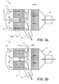
- Fig. 2a and Fig. 2b shows two schematic side views of two embodiments of the inventive exhaust gas aftertreatment device 1, each comprising one possible development of reductant injection arrangement.
- the second converter substrate is a substrate with SCR functionality 26.
- a reductant typically anhydrous ammonia, aqueous ammonia urea etc.
- Operations and the functionality of a substrate with SCR functionality are not further described herein since this is common knowledge and does not form part of the invention. According to the development of the invention shown in Fig.
- a first example of an injector pipe 25a is provided longitudinally in the catalytic converter 2, wherein the injector pipe 25a enters the catalytic converter 2 through the second end portion 6, such that a reductant can be added to the exhaust gas emissions before the substrate with SCR functionality26.
- the reductant may preferably be added within the volume of the exhaust gas guiding means 12 or the volume of the pipe member 11, such that the beneficial mixing properties provided by the exhaust gas guiding means 12 and the pipe member 11 is facilitated to provide high degree of mixing between the reductant and the exhaust gas emissions. Also, this will improve the evaporation of the reductant since it will be exposed to hot exhaust gas emissions and possibly heated components for a longer period of time.
- the injector pipe 25a is provided such that it extends substantially centrally of the pipe member 11, into the volume of the exhaust gas guiding means 12.
- a second example of an injector pipe 25b is entering the volume of the exhaust gas guiding means 12 in a direction substantially perpendicular to the extension of the catalytic converter 2.
- the injector pipe 25b inserted through the midsection 5 of the encapsulating member 3. This arrangement allows the reductant to be added to the exhaust gas emission flow within the area of the exhaust gas guiding means 12.
- the second example of an injector pipe can also be provided such that the reductant is injected to the exhaust gas emission flow within the volume of the pipe member 11.
- Fig. 2a and Fig. 2b shows developments of the inventive exhaust gas aftertreatment device 1 where the first port 10 receives exhaust gas emissions from an ICE (not shown) and exhaust gas emissions are discharged through the second port 15.
- the intended exhaust gas flow is indicated by arrows in before mentioned figures.
- any injector pipe is preferably arranged to a reductant tank (not shown) and to associated components for controlling and enabling the injection of reductant. This is not further described herein since this is common knowledge and does not form part of the invention.
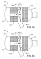
- Fig. 3a and Fig. 3b shows two schematic side views of the exhaust gas aftertreatment device 101 comprising two developments of exhaust gas guiding means 1012 according to the invention.
- the curved section 1024 is provided between the first open section 1013 and the second open section 1014 of the exhaust gas guiding means 1012.
- the entire circumferential surface connecting the first open section 1013 to the second open section 1014 is curved. It is also possible that just a smaller section of the circumferential surface is curved.
- the curved section 1024 connects the first open section 1013 with the second open section 1014 by forming a circumferential surface of the exhaust gas guiding means 1012. Additionally, in the development of the inventive exhaust gas aftertreatment device 101 shown in Fig. 3a and Fig. 3b , the curved section 1024 is provided with a circumferential section 1027a;1027b, wherein the circumferential section 1027a;1027b is provided substantially in the middle of the curved section 1024.
- the circumferential section 1027a;1027b is preferably configured to add additional resilience, or in other ways desirable, properties to the exhaust gas guiding means 1012.
- the circumferential section 1027a is in the form of a membrane, which membrane can be configured to add additional ability to withstand thermal expansion, or add other desirable properties to the exhaust gas guiding means 1012, and in Fig. 3b , the circumferential section 1027b is in the form of a corrugated section of the curved section 1024, which also can improve the resilience of the curved section 1024.
Landscapes
- Engineering & Computer Science (AREA)
- Chemical & Material Sciences (AREA)
- Chemical Kinetics & Catalysis (AREA)
- Combustion & Propulsion (AREA)
- Mechanical Engineering (AREA)
- General Engineering & Computer Science (AREA)
- Health & Medical Sciences (AREA)
- Toxicology (AREA)
- Exhaust Gas After Treatment (AREA)
Abstract
Description
- The present invention relates to an exhaust gas aftertreatment device for an Internal Combustion Engine (ICE), and more specifically to a compact exhaust gas aftertreatment device comprising two catalytic converter substrates and an advanced exhaust gas emission guiding system, providing improved exhaust gas emissions mixing properties. Additionally, the invention comprises means for reducing induced thermal expansion due to heat load from exhaust gas emissions, and an exhaust gas aftertreatment device provided with such means.
- Today, in order to fulfill current emission legislation, more or less all vehicles with an Internal Combustion Engine (ICE) are provided with an exhaust gas aftertreatment device comprising some kind of catalytic converter.
- The catalytic converter for reduction of exhaust gas emissions from an ICE generally consists of a tubular, longitudinal body with an inlet and an outlet, wherein the inlet is arranged on the exhaust side of the ICE, for receiving exhaust gas emissions from the ICE, and an outlet is arranged for discharging exhaust gas emissions treated in the catalytic converter. The inlet is in flow communication with the outlet. Additionally, the catalytic converter generally comprises at least one catalytic converter substrate arranged between the inlet and the outlet of the catalytic converter. A catalytic converter substrate generally comprises a channeled structure which the exhaust gases can pass through while being exposed to the large surface area of the catalytic converter. For petrol engines the most frequently used catalytic converter substrate is generally Three Way Catalyst (TWC), while Diesel Oxidation Catalyst (DOC) and/or Lean NOx Trap (LNT) generally are most frequently used for diesel engines. It is also preferred that the TWC or the DOC/LNT is supplemented by a substrate with SCR functionality (SCR) for improved NOx reduction. The underlying mechanisms and the selection of catalytic converter are not part of the invention per se and is not further discussed herein.
- However, using more than one catalytic converter substrate can be problematic since catalytic converters often are associated with design restrains due to the limited available space in the engine compartment of passenger cars. Small catalytic converters are preferred from an engine packaging perspective, but small catalytic converters usually means that the flow distance between the inlet and the catalytic converter substrates of the catalytic converter is limited. Limited distance means that the time and distance during which mixing of the exhaust gas emissions can occur is limited. Insufficient mixing of the exhaust gas emissions gives inhomogeneous exhaust gas emission mixture. This might e.g. be problematic for emission gas sensors, arranged in the exhaust gas emission flow, to work properly and give accurate emission measurements.
- Other problematic areas for catalytic converters are high back pressure and insufficiently heating. Heating of the catalytic converter is crucial since the catalytic converter is most effective at relatively high temperatures. Thus, it is desirable that catalytic converter reaches its optimum operation temperatures as soon as possible. However, at the same time high temperatures, and big fluctuations in temperature, is stressful for the components of the catalytic converter. Different approaches are used in order for the catalytic converter to reach desired operation temperature as quickly as possible, e.g. the combustion and fuel injection of the engine may be controlled for generating additional heat or the catalytic converter may be arranged as close to the engine exhaust gas emissions outlet as possible, where the exhaust gas emissions are warmest.
- Insufficient mixing of the exhaust gas emissions are of particular interest if a substrate with SCR functionality is used. For substrates with SCR functionality, a liquid or gaseous reductant is introduced in the exhaust gas emission flow in order for the reductant and exhaust gas emissions to mix before the substrate with SCR functionality. Consequently, sufficient mixing is essential for the substrate with SCR functionality to work properly.
-
US 2012/0110989 , herein considered to be incorporated by reference, discloses an exhaust-gas aftertreatment device for an internal combustion engine, wherein the device comprises a catalytic converter comprising a tubular member, a pipe member, one catalytic converter substrate and a deflector means. By utilizing the pipe member and the deflector means, the catalytic converter arrangement according toUS 2012/0110989 provides prolonged mixing period before the single catalytic converter for improved efficiency. Also, the pipe member and the deflector means are configured to reduce the amount of emissions in liquid form before the exhaust gas emissions reaches the single catalytic converter by using heat transferred from the exhaust gas emissions to the pipe member and the deflector means. This effect is additionally promoted by arranging a layer of porous material between the downstream side of the pipe member and the deflector means. - However, there is still a need for further improvements.
- The object of the present invention is to provide an improved exhaust gas aftertreatment device, comprising an inventive catalytic converter, for an ICE where some of the previously mentioned problems are partly avoided. The invention provides a compact catalytic converter comprising two catalytic converter substrates. Even thou the inventive catalytic converter is compact and comprises two catalytic converter substrates, the inventive catalytic converter of the inventive exhaust gas aftertreatment device provide improved mixing properties. Additionally, another object of the present invention is to provide an inventive exhaust gas guiding means overcoming the problem with thermally induced stress in guiding means of catalytic converters.
- The inventive exhaust gas aftertreatment device comprises an inventive catalytic converter, wherein the inventive catalytic converter comprises an encapsulating member. The encapsulating member comprises a first and a second end portion, wherein the second end portion is arranged in the opposite end of the catalytic converter as the first end section, and a midsection of the encapsulating member arranged there between.
- In a preferred development of the inventive catalytic converter, the encapsulating member can have a tubular cross sectional shape, but it is also possible to use an elliptic cross sectional shape, a cross sectional shape being more or less rectangular or any other suitable shape such as an irregularly shaped cross sectional shape. The form of the encapsulating member is dependent on available space in the engine compartment and other design restraints.
- The outside of the encapsulating member defines the outer perimeter of the catalytic converter, wherein the inside of the encapsulating member defines a converter volume of the catalytic converter. Within the encapsulating member, a first catalytic converter substrate and a second catalytic converter substrate are arranged.
- The inventive exhaust gas aftertreatment device, and the inventive catalytic converter of the inventive exhaust gas aftertreatment device, is characterized in that within the converter volume, starting from the first end portion, the following is provided in order:
- a first volume being defined between the first end portion of the encapsulating member and the first catalytic converter substrate,
- the first catalytic converter substrate being arranged between the first volume and a subsequently provided second volume,
- the second volume being defined between the first catalytic converter substrate and the second catalytic converter substrate, wherein the first volume is in fluid communication with the second volume through the first catalytic converter substrate,
- the second catalytic converter substrate being arranged between the second volume and a subsequently provided third volume, and
- the third volume being defined between the second catalytic converter substrate and the second end portion of the encapsulating member, wherein the third volume is in fluid communication with the second volume through the first catalytic converter substrate.
- Consequently, in order to clearly describe the invention the first, second and third volumes are defined as being delimited by the outer delimitation of the first and second catalytic converter substrates, even thou in reality exhaust gas encapsulated by a catalytic converter substrate is able to flow through the substrate.
- Additionally, the catalytic converter of the exhaust gas aftertreatment device comprises an exhaust gas guiding means and a pipe member within said encapsulating member. By arranging the exhaust gas guiding means and the pipe member as will be described, the flow path of the exhaust gas emissions will be prolonged which is beneficial from an exhaust gas mixing perspective.
- The exhaust gas guiding means is arranged in the second volume of the catalytic converter. A first open section of the exhaust gas guiding means is connected to the pipe member, as will be further described below, and seals against the pipe member, preferably the edge of the pipe member. A second open section of the Exhaust gas guiding means is arranged adjacent the first catalytic converter substrate, whereas the second open section of the exhaust gas guiding means seals against the encapsulating member. This arrangement divides the second volume into a first part of the second volume and a second part of the second volume. The first part of the second volume is provided adjacent to the first catalytic converter substrate and the second part of the second volume is provided adjacent to the second catalytic converter substrate.
- According to a development of the inventive exhaust gas aftertreatment device, comprising the inventive catalytic converter, the pipe member is extending in the longitudinal direction of the catalytic converter and is located centrally in the encapsulating member, more precisely centrally within the second substrate. Arranging the pipe member centrally in the second substrate encapsulating the pipe member can be advantageous in order to have an even and flow of exhaust gas emissions through the catalytic converter. However, arranging the pipe member in another way may give other advantages.
- According to a preferred development of the invention, the pipe member has the same length as the second catalytic converter substrate. However, it is also possible to provide the end portion of the pipe member adjacent to the third volume with an outlet funnel arrangement for control of the flow behavior of the exhaust gas emissions when entering the third volume.
- The cross sectional area of the first open section of the exhaust gas guiding means is smaller than the cross sectional area of the second open section of the exhaust gas guiding means. Consequently, the exhaust gas guiding means is arranged as a funnel placed after the first catalytic converter substrate such that a flow of exhaust gas emissions, after passing the first catalytic converter substrate, will be collected in the exhaust gas guiding means and guided by the tapered shape of the exhaust gas guiding means to and through the pipe member. The pipe member is arranged within the second converter substrate, and consequently the exhaust gas emissions will be guided, from the second volume to the third volume, without passing the second catalytic converter substrate. Since the cross sectional area of the second open section of the exhaust gas guiding means is larger than the cross sectional area of the first open section and the cross sectional area of the pipe member there will be an increase in the exhaust gas flow rate over the exhaust gas guiding means and the subsequently arranged pipe member. The increase in exhaust gas flow rate is beneficial from an exhaust gas emission mixing perspective.
- According to the invention, a first port is connected to the first end portion for fluid communication with the converter volume and a second port is connected to the midsection portion of the encapsulating member for fluid communication with the second part of the second volume.
- In a preferred development of the inventive catalytic converter, the first port is configured to receive exhaust gas emissions from the ICE. The exhaust gas emission flow will according to this development be directed from the first port to the second port. The flow will according to this development be directed in a first flow direction A through the first port and into the first volume. From the first port the exhaust gas flow will thereafter pass the first catalytic converter substrate into the first part of the second volume. The exhaust gas emission flow is thereafter directed from the first part of the second volume, through the exhaust gas guiding means and the pipe member, to the third volume. The flow through the exhaust gas guiding means and the pipe member will be directed in a first flow direction A.
- According to the invention the second end portion of the encapsulating member forms a deflector means, configured to deflect the exhaust gas emissions, such that the direction of the exhaust gas flow is changed.
- Once having entered the third volume in the first flow direction A, the exhaust gas emission flow will reach the deflector means, at which the flow direction of the exhaust gas emission will be deflected into a second flow direction B. The second flow direction B is preferably substantially opposite to the first flow direction A. The change of flow direction will contribute to the mixing of the exhaust gas emissions.
- After the change of flow direction into the second flow direction B the exhaust gas emissions will flow from the third volume into the second part of the second volume through the second catalytic converter substrate. Hence, as mentioned, by using the exhaust gas guiding means, the pipe member and the deflector means such that the exhaust gas emission flow, after passing the first catalytic converter substrate, will flow through the exhaust gas guiding means, the pipe member and be deflected in the third volume by the deflector means before reaching the second catalytic converter substrate instead of flowing directly to the second catalytic converter substrate, the distance the exhaust gas emissions has to travel after passing the first catalytic converter substrate is prolonged. This is beneficial for the mixing of the exhaust gas emissions. The prolonged mixing period before the exhaust gas emissions reaches the second catalytic converter will improve the efficiency of the second catalytic converter substrate.
- In this development of the invention the exhaust gas emissions will be discharged from the second part of the second volume through the second port in a third flow direction C.
- In developments of the inventive exhaust gas aftertreatment device where the exhaust gas emissions enters the first port in a first flow direction A and is discharged from the exhaust gas aftertreatment device in a third flow direction C, and where the inventive exhaust gas aftertreatment device is used for treating exhaust gas emissions from a diesel engine, the first catalytic converter substrate is a preferably a Diesel Oxidation Catalyst and/or Lean NOx Trap, referred to as DOC/LNT. If a petrol engine is used the first catalytic converter substrate is preferably a Three Way Catalyst (TWC). Independently of if the inventive exhaust gas aftertreatment device is used for a diesel or petrol engine, the second catalytic converter substrate is preferably a substrate with SCR functionality (SCR). In this context, a substrate with SCR functionality may be any substrate, filter, monolith or like that can be provided with a coating with selective catalytic reduction functionality and that has the essential properties such as that a gaseous media can flow through the substrate that is required of such substrate. Receiving exhaust gas emissions in the first port and discharging treated exhaust gas emissions from the second port has the advantage that the flow path for the first port to the second port is optimized for flow in that direction, e.g. in regards of mixing properties. The catalytic functionality of the first and second catalytic converter substrates are not part of the invention per se, and variations known for a person skilled in the art are considered to be within the scope of the inventive concept.
- However, according to another development of the invention reversed flow can also be used. For developments where reversed flow is used the exhaust gas flow is directed from the second port to the first port. In this development the second catalytic converter will be the first catalytic converter the exhaust gases passes and the first catalytic converter will be arranged downstream of the second catalytic converter.
- Consequently, the second port will receive exhaust gas emissions from an ICE and the exhaust gas emissions will be discharged from the first port. In this development of the invention the second catalytic converter substrate is preferably a DOC/LNT for diesel engines and a TWC for petrol engines. The first catalytic converter substrate is preferably a substrate with SCR functionality.
- Developments of the invention where the exhaust gas flow is directed from the second port to the first port is not further discussed herein, but one should bear in mind that this is a possible development of the invention, with accompanying advantages and disadvantages.
- The advantages, disadvantages and effects of selecting possible catalytic converter substrates are not further disclosed herein since this is common knowledge for a person skilled in the art.
- In SCR systems a reductant is added to the exhaust gas flow in order for the substrate with SCR functionality to reduce NOx. The reductant, such as e.g. urea, anhydrous ammonia or aqueous ammonia, is added to the exhaust gas emission flow and can be absorbed by the downstream arranged substrate with SCR functionality where it reacts with the NOx of the exhaust gas emission. If the reductant is in liquid form the reductant is generally sprayed into the exhaust gas emission flow as small droplets, and it is desirable that the reductant is vaporized before reaching the substrate with SCR functionality. Good mixing of the exhaust gases with the added reductant, warm engine components and sufficient time before reaching the substrate with SCR functionality are all factors which contribute to high degree of evaporation. Gaseous reductant may be added either from any form of gas container or by gasification of a solid substrate. Consequently, the good mixing properties of the inventive exhaust gas aftertreatment device are advantageous.
- If a substrate with SCR functionality is present, a reductant must be added to the exhaust gas emission flow upstream of the substrate with SCR functionality. Consequently, in preferred developments of the exhaust gas aftertreatment device the reductant is either injected in the exhaust gas flow within the volume of the pipe member or within the volume of the exhaust gas guiding means. The reductant is injected into the exhaust gas emission flow by means of an injector pipe. The injector pipe is connected to a reductant tank and other necessary components for executing the injection and for controlling the injection. The injector pipe can be inserted through the encapsulating member either by extending through the deflector means of the second end portion or by extending through the encapsulating member, and if so preferably the midsection of the encapsulating member. In a development where the injector pipe is located within the pipe member, it is preferred that the injector pipe is located substantially centrally in the pipe member, extending in the longitudinal direction thereof. In the development where the injector pipe is extending through the midsection of the encapsulating member, the injector pipe is protruding into the volume of the pipe member, or within the volume of the exhaust gas guiding means, in a direction being substantially perpendicular to the first flow direction A.
- By injecting the reductant within the volume of either the pipe member or the exhaust gas guiding means it is ensured that the reductant is sufficiently mixed with exhaust gas emission flow. The closer to the first catalytic converter the reductant is injected, the better mixing and the longer the time for evaporation of the reductant before it reaches the second catalytic converter, preferably being a substrate with SCR functionality if the exhaust emission flow is directed from the first port to the second port.
- According to yet a development of the inventive exhaust gas aftertreatment device, the deflector means is provided with a porous material. The porous material can be provided to absorb and thereby facilitate retention of any liquid substance in the exhaust gas emission until the liquid substance is evaporated, e.g. by that the porous material has been heated such that any absorbed liquid substance is evaporated into gaseous form. According to a preferred development of the invention, the reductant can be injected in the exhaust gas emission flow upstream of the porous material. Consequently, unevaporated reductant can be absorbed by the porous material until it is evaporated. The porous material may consist of a mesh structure, such as for a catalytic converter substrate, or be of any other suitable structure.
- According to one development of the inventive exhaust gas aftertreatment device, the porous material can be arranged at a distance from the second end portion such that an open volume is formed between the porous material and the second end portion.
- Furthermore, the inventive exhaust gas aftertreatment device comprises an inventive exhaust gas guiding means. The exhaust gas guiding means is provided within the converter volume, such that the exhaust gas guiding means can guide the exhaust gas flow as is desired.
- The exhaust gas guiding means may comprise a resilient section that is configured to change shape when the exhaust gas guiding means are exposed to hot exhaust gas emissions. This can prevent that stress or tension in said guiding means is created on the inside of the encapsulating member due to thermal stress induced by the hot exhaust gas emissions.
- According to one preferred embodiment of the invention, the resilient section of the exhaust gas guiding means comprises a curved section between the first open section and the second open section, wherein said curved section can change degree of curvature and thus take up heat induced stress. The circumferential surface of the exhaust gas guiding means comprising the curved section is preferably shaped to be outwardly concave, such that an inwardly, convex tapering of the passage between the second open section and the first open section is provided.
- According to a another development of the inventive exhaust gas guiding means the resilient section of the exhaust gas guiding means can be provided with a circumferential membrane, configured to absorb stress induced in the component. The circumferential membrane may be provided anywhere along the circumferential surface of the exhaust gas guiding means, but according to a preferred embodiment the membrane can be provided at the second open section, adjacent to where the exhaust gas guiding means seals against the midsection of the encapsulating member.
- According to yet another development of the inventive exhaust gas guiding means, the resilient section of the exhaust gas guiding means can be provided with a corrugated circumferential section. Also the corrugated circumferential section can be provided anywhere along the circumferential surface of the exhaust gas guiding means, but preferably adjacent to where the exhaust gas guiding means seals against the midsection of the encapsulating member. Using a corrugated circumferential section, also providing improved ability to absorb heat induced stress, has the advantage that the corrugated section can be manufactured from the same metallic sheet used to form the exhaust gas guiding means.
- As stated, the inventive exhaust gas guiding means can preferably be used as the exhaust gas guiding means of the inventive exhaust gas aftertreatment device. However, the inventive exhaust gas guiding means can also be used in other exhaust gas aftertreatment devices. Problems due to that components of exhaust gas aftertreatment devices are exposed to hot exhaust gas emissions, causing thermal expansion of exposed components, is common for all exhaust gas aftertreatment devices.
- As will be realised, it is possible to modify the invention in various obvious respects, all without departing from the scope of the appended claims. Accordingly, the accompanying schematically drawings and the description thereto are to be regarded as illustrative in nature and not restrictive. Reference signs mentioned in the claims should not be seen as limiting the extent of the matter protected by the claims, and their sole function is to make the claims easier to understand.
-
-
Fig. 1 shows a schematic view of a development of the exhaust gas aftertreatment device, according to the present invention, -
Fig. 2a and Fig. 2b shows two schematic views of the exhaust gas aftertreatment device, comprising two developments of reductant injection arrangements, according to the invention, and -
Fig. 3a and Fig. 3b shows two schematic views of the exhaust gas aftertreatment device comprising two developments of exhaust gas guiding means, according to the invention. -
Fig. 1 shows an embodiment of an inventive exhaustgas aftertreatment device 1 for an Internal Combustion Engine (ICE) (not shown), comprising acatalytic converter 2. Thecatalytic converter 2 comprises an encapsulatingmember 3. In turn, the encapsulatingmember 3 comprises afirst end portion 4, asecond end portion 6, wherein thesecond end portion 6 is provided at the opposite end of thecatalytic converter 2 as thefirst end portion 4, and amidsection 5, wherein themidsection 5 is provided between thefirst end portion 4 and thesecond end portion 6 such that themidsection 5 connects thefirst end portion 4 with thesecond end portion 6. The outside of the encapsulatingmember 3 defines an outer perimeter of thecatalytic converter 2 and the inside of the encapsulatingmember 3 defines aconverter volume 7 of thecatalytic converter 2. According to the invention the cross sectional area of the encapsulatingmember 3 can be of any suitable shape, such as round, rectangular, square etc. A firstcatalytic converter substrate 8 and a secondcatalytic converter substrate 9 are arranged within the encapsulatingmember 3. The first catalytic converter substrate can preferably be a Diesel Oxidation Catalyst (DOC) and/or a Lean NOx Trap (LNT) or a Three Way Catalyst (TWC) and the second catalytic converter substrate can preferably be a substrate with SCR functionality (SCR). - The functionality of the possible catalytic substrates, used as first and second catalytic converter substrate, are not described herein since this is considered to be part of common knowledge.
- According to the embodiment of the invention shown in
Fig. 1 , theconverter volume 7 is divided in afirst volume 21, asecond volume 22 and athird volume 23, wherein thefirst volume 21 is provided adjacent to the firstcatalytic converter substrate 8, thethird volume 23 is provided adjacent to the secondcatalytic converter substrate 9 and thesecond volume 22 is provided between the firstcatalytic converter substrate 8 and the secondcatalytic converter substrate 9. - Additionally, an exhaust gas guiding means 12 is arranged within the encapsulating
member 3 in thesecond volume 22. The exhaust gas guiding means 12 comprises a firstopen section 13 and a secondopen section 14, wherein the firstopen section 13 is substantially smaller than the secondopen section 14. The first and secondopen sections 13;14 are connected by a circumferential surface. As shown inFig. 1 the exhaust gas guiding means 12 comprises acurved section 24 between the firstopen section 13 and the secondopen section 14. Thecurved section 24 is provided such that when the exhaust gas guiding means 12 is exposed to hot exhaust gas emissions, which if the exhaust gas guiding means 12 is provided in a metallic material can cause thermal expansion of the exhaust gas guiding means 12, thecurved section 24 can absorb stress created in the metallic material due to said thermal expansion, and thus prevent excess force on the inside of the encapsulatingmember 5. Thecurved section 24 makes the exhaust gas guiding means 12 resilient to hot exhaust gas emissions. - As is obvious since the first
open section 13 has smaller cross sectional area than the secondopen section 14, thecurved section 24 of the exhaust gas guiding means 12 is slightly tapered. According tofig. 1 is the circumferential surface of the exhaust gas guiding means 12 tapered in an inwardly convex manner. - The first
open section 13 is arranged to apipe member 11 such that a circumferential edge of the firstopen section 13 seals against the circumferential edge of thepipe member 11. The secondopen section 14 is circumferentially arranged to themidsection 5 of the encapsulatingmember 3 such that the secondopen section 14 seals against themidsection 5 of the encapsulatingmember 3. This arrangement provides that thesecond volume 22 is divided into a first part of thesecond volume 22a and a second part of thesecond volume 22b. The cross sectional area of thepipe member 11 as well as the exhaust gas guiding means 12 can be of any suitable shape, such as round, rectangular, square etc., as long as the exhaust gas guiding means 12 can be arranged to seal against thepipe member 11 and themidsection 5 of the encapsulatingmember 3. - According to the invention disclosed in
Fig. 1 thepipe member 11 is provided within the secondcatalytic converter substrate 9, wherein thepipe member 11 is extending in the longitudinally direction of thecatalytic converter 2, such that saidpipe member 11 is connecting the first part of thesecond volume 22a with thethird volume 23. Thepipe member 11 provides improved mixing of the exhaust gases by guiding said exhaust gases in a first flow direction A from said first part of thesecond volume 22a to saidthird volume 23 by prolonging the mixing period before the exhaust gases reaches the secondcatalytic converter substrate 9. Thus, thepipe member 11 enables that thecatalytic converter 2, comprising twocatalytic converter substrates 8;9, can be designed to be more compact without having negative impact on the exhaust gas emissions mixing characteristics. According to the embodiment if the inventivecatalytic converter 2 disclosed inFig. 1 thepipe member 11 is arranged substantially centrally in the secondcatalytic converter 9. - Additionally, according to the embodiment of the invention shown in
Fig. 1 afirst port 10 is arranged in connection to thefirst volume 21. According to the embodiment inFig. 1 thefirst port 10 is acting as an inlet port receiving exhaust gases from the ICE (not shown). The exhaust gases will enter the first port in a first flow direction A. Asecond port 15 is arranged in fluid connection to the second part of thesecond volume 22b, wherein thesecond port 15 according to the embodiment in Fig. 10 is acting as an outlet port discharging exhaust gases after catalytic conversion thereof. The discharged exhaust gases will flow through the second port in a third flow direction C. Thefirst port 10 and thesecond port 15 can be formed together with the encapsulatingmember 3 or be separate components arranged to the encapsulatingmember 3. - Additionally, according to the embodiment of the invention shown in
Fig. 1 a portion of thesecond end portion 6 constitutes a deflector means 18. The deflector means 18 deflects the exhaust gases from thepipe member 11, wherein the exhaust gases approaches the deflector means 18 in the first flow direction A, in a second flow direction B. According to the embodiment inFig. 1 , the second flow direction B is substantially opposite to the first flow direction A. Mixing of the exhaust gases is further promoted by this deflection, resulting in improved catalytic conversion by the secondcatalytic converter substrate 9. - Finally, the
catalytic converter 2 comprises aporous material 16. According to the embodiment of the invention shown inFig. 1 , the porous material is 16 provided at the end of thethird volume 23 provided furthest away from thefirst port 10, adjacent to the deflector means 18. Theporous material 16 is arranged between thepipe member 11 and the portion of thesecond end portion 6 constituting the deflector means 18, such that a flow flowing through thepipe member 11 in the first flow direction A is directed at theporous material 16 before reaching the deflector means 18. The porous material is arranged at a distance from the deflector means 18 such that aspace 17 is formed between theporous material 16 and the deflector means 18. - According to the embodiment of the inventive exhaust
gas aftertreatment device 1 shown inFig. 1 , the exhaust gas aftertreatment device is configured to function as follows: - Exhaust gases from the ICE (not shown) is entering the
catalytic converter 2 of the exhaustgas aftertreatment device 1 through thefirst port 10 in a first flow direction A. When entering thefirst volume 21 the exhaust gas flow rate is decreased, enabling the exhaust gases to flow through the subsequently arranged firstcatalytic converter substrate 8 at lower rate. After the firstcatalytic converter substrate 8, the exhaust gases enter the first part of thesecond volume 22a. The subsequently arranged exhaust gas guiding means 12 guides the exhaust gas flow into thepipe member 11. The cross sectional area of thepipe member 11 and the firstopen section 13 of the exhaust gas guiding means 12, wherein the firstopen section 13 is arranged to the edge of thepipe member 11, is smaller than the cross sectional area of the secondopen section 14 of the exhaust gas guiding means 12, resulting in an increased exhaust gas flow rate through thepipe member 11. The increase in exhaust gas flow rate will improve the mixing of the exhaust gas, thus contribute to improved catalytic conversion. The exhaust gas emissions will flow through the pipe member in a first flow direction A into thethird volume 23, wherein the flow rate once again will be decreased. According toFig. 1 theporous material 16 is arranged in the flow direction A downstream of thepipe member 11, such that the exhaust gas flow will pass through theporous material 16. After passing theporous material 16, the exhaust gases reaches the deflector means 18. The deflector means will redirect the exhaust gas flow in the second flow direction B. The exhaust gas emissions will thereafter pass through the secondcatalytic converter substrate 9, in the second flow direction B, and into the second part of thesecond volume 22b. Finally, the exhaust gas emissions will exit through thesecond port 15 in the third flow direction C. The inventivecatalytic converter 2 can also be provided without the porous material. -
Fig. 2a and Fig. 2b shows two schematic side views of two embodiments of the inventive exhaustgas aftertreatment device 1, each comprising one possible development of reductant injection arrangement. According toFig. 2a and 2b , the second converter substrate is a substrate withSCR functionality 26. The presence of a substrate with SCR functionality26 requires that a reductant, typically anhydrous ammonia, aqueous ammonia urea etc., is added to the exhaust gas emissions flow and is absorbed onto the downstream arranged substrate with SCR functionality. Operations and the functionality of a substrate with SCR functionality are not further described herein since this is common knowledge and does not form part of the invention. According to the development of the invention shown inFig. 2a , a first example of aninjector pipe 25a is provided longitudinally in thecatalytic converter 2, wherein theinjector pipe 25a enters thecatalytic converter 2 through thesecond end portion 6, such that a reductant can be added to the exhaust gas emissions before the substrate with SCR functionality26. The reductant may preferably be added within the volume of the exhaust gas guiding means 12 or the volume of thepipe member 11, such that the beneficial mixing properties provided by the exhaust gas guiding means 12 and thepipe member 11 is facilitated to provide high degree of mixing between the reductant and the exhaust gas emissions. Also, this will improve the evaporation of the reductant since it will be exposed to hot exhaust gas emissions and possibly heated components for a longer period of time. Further, according toFig. 2a , theinjector pipe 25a is provided such that it extends substantially centrally of thepipe member 11, into the volume of the exhaust gas guiding means 12. - According to the development of the inventive exhaust
gas aftertreatment device 1 shown inFig. 2b , a second example of aninjector pipe 25b is entering the volume of the exhaust gas guiding means 12 in a direction substantially perpendicular to the extension of thecatalytic converter 2. In the development of the invention according tofig. 2b is theinjector pipe 25b inserted through themidsection 5 of the encapsulatingmember 3. This arrangement allows the reductant to be added to the exhaust gas emission flow within the area of the exhaust gas guiding means 12. According to a further development of the inventive exhaustgas aftertreatment device 1, the second example of an injector pipe can also be provided such that the reductant is injected to the exhaust gas emission flow within the volume of thepipe member 11. -
Fig. 2a and Fig. 2b shows developments of the inventive exhaustgas aftertreatment device 1 where thefirst port 10 receives exhaust gas emissions from an ICE (not shown) and exhaust gas emissions are discharged through thesecond port 15. In view of this, the intended exhaust gas flow is indicated by arrows in before mentioned figures. Also, in the developments of the inventive exhaust gas aftertreatment device shown inFig. 2a and Fig. 2b , any injector pipe is preferably arranged to a reductant tank (not shown) and to associated components for controlling and enabling the injection of reductant. This is not further described herein since this is common knowledge and does not form part of the invention. -
Fig. 3a and Fig. 3b shows two schematic side views of the exhaustgas aftertreatment device 101 comprising two developments of exhaust gas guiding means 1012 according to the invention. According to the development of the inventive exhaustgas aftertreatment device 101 shown inFig. 3a and Fig. 3b , thecurved section 1024 is provided between the firstopen section 1013 and the secondopen section 1014 of the exhaust gas guiding means 1012. In the developments of the invention shown inFig. 3a and Fig. 3b the entire circumferential surface connecting the firstopen section 1013 to the secondopen section 1014 is curved. It is also possible that just a smaller section of the circumferential surface is curved. Thecurved section 1024 connects the firstopen section 1013 with the secondopen section 1014 by forming a circumferential surface of the exhaust gas guiding means 1012. Additionally, in the development of the inventive exhaustgas aftertreatment device 101 shown inFig. 3a and Fig. 3b , thecurved section 1024 is provided with acircumferential section 1027a;1027b, wherein thecircumferential section 1027a;1027b is provided substantially in the middle of thecurved section 1024. Thecircumferential section 1027a;1027b is preferably configured to add additional resilience, or in other ways desirable, properties to the exhaust gas guiding means 1012. - In
Fig. 3a , thecircumferential section 1027a is in the form of a membrane, which membrane can be configured to add additional ability to withstand thermal expansion, or add other desirable properties to the exhaust gas guiding means 1012, and inFig. 3b , thecircumferential section 1027b is in the form of a corrugated section of thecurved section 1024, which also can improve the resilience of thecurved section 1024. - Finally, the operations of a catalytic converter and additional components of catalytic converters not described herein are considered to be part of common knowledge and does not form part of, nor have any impact on, the present invention.
Claims (15)
- An exhaust gas aftertreatment device (1) for an Internal Combustion Engine wherein the exhaust gas aftertreatment device (1) comprises a catalytic converter (2), wherein the catalytic converter (2) comprises
an encapsulating member (3) comprising a first and a second opposing end portions (4;6), and a midsection portion (5) arranged there between,
wherein an outside of the encapsulating member (3) defines the outer perimeter of the catalytic converter (2), and wherein the inside of the encapsulating member (3) defines a converter volume (7) of the catalytic converter (2),
wherein a first catalytic converter substrate (8) and a second catalytic converter substrate (9) are arranged within the converter volume (7) of the catalytic converter (2),
and wherein a first port (10) is connected to the first end portion (4) for fluid communication with the converter volume (7),
characterized in
that within the converter volume (7), starting from the first end portion (4), the following is provided in order:• a first volume (21) being defined between the first end portion (4), and the first catalytic converter substrate (8),• the first catalytic converter substrate (8) being arranged between the first volume (21) and a subsequently provided second volume (22),• the second volume (22) being defined between the first catalytic converter substrate (8) and the second catalytic converter substrate (9), wherein the first volume (21) is in fluid communication with the second volume (22) through the first catalytic converter substrate (8),• the second catalytic converter substrate (9being arranged between the second volume (22) and a subsequently provided third volume (23), and• the third volume (23) being defined between the second catalytic converter substrate (9) and the second end portion (6), wherein the third volume (23) is in fluid communication with the second volume (22) through the second catalytic converter substrate (9),wherein the exhaust gas aftertreatment device (1) additionally comprises an exhaust gas guiding means (12) and a pipe member (11) within said encapsulating member (3), wherein the pipe member (11) is arranged within the second converter substrate (9) and connects the second volume (22) with the third volume (23) for fluid communication, and wherein the exhaust gas guiding means (12) is arranged in the second volume (22),
wherein a first open section (13) of the exhaust gas guiding means (14) is connected to the pipe member (11) and sealed against the pipe member (11), and a second open section (14) of the exhaust gas guiding means (12) is arranged adjacent the first catalytic converter substrate (8),
wherein the second open section (14) of the exhaust gas guiding means (12) seals against the midsection portion (5) of the encapsulating member (3) such that the second volume (22) is divided into a first part of the second volume (22a) and a second part of the second volume (22b),
wherein the first part of the second volume (22a) is provided adjacent to the first catalytic converter substrate (8) and the second part of the second volume (22b) is provided adjacent to the second catalytic converter substrate (9),
wherein a second port (15) is connected to the midsection portion (5) of the encapsulating member (3) for fluid communication with the second part of the second volume (22b),
and wherein the cross sectional area of the first open section (13) of the exhaust gas guiding means (12) is smaller than the cross sectional area of the second open section (14) of the exhaust gas guiding means (12). - The exhaust gas aftertreatment device (1) according to claim 2,
characterized in
that the exhaust gas guiding means (12) comprises a resilient section that changes shape when the exhaust gas guiding means (12) changes shape due to change in heat load from the exhaust gas emissions, for hindering excess force on the inside of the encapsulating member (3). - The exhaust gas aftertreatment device (1) according to claim 2,
characterized in
that the exhaust gas guiding means (12) comprises a curved section (24) between the first open section (13) and the second open section (14), which curved section (24) changes shape when the exhaust gas guiding means (12) changes shape due to change in heat load from the exhaust gas emissions, for hindering excess force on the inside of the encapsulating member (3). - The exhaust gas aftertreatment device (1) according to claim any of the preceding claims,
characterized in
that the pipe member (11) is located centrally in the encapsulating member (3) of the catalytic converter (2), extending in the longitudinal direction thereof. - The exhaust gas aftertreatment device (1) according to claim any of the preceding claims,
characterized in
that the second end portion (6) forms a deflector means (18), configured to deflect the exhaust gas emissions. - The exhaust gas aftertreatment device (1) according to any of the preceding claims,
characterized in
that the exhaust gas emission flow is directed from the first port (10) to the second port (15). - The exhaust gas aftertreatment device (1) according to claim 6,
characterized in
that the first catalytic converter substrate (8) is a Diesel Oxidation Catalyst, DOC, and/or a Lean NOx Trap, LNT. - The exhaust gas aftertreatment device (1) according to claim 6,
characterized in
that the first catalytic converter substrate (8) is a Three Way Catalyst, TWC. - The exhaust gas aftertreatment device (1) according to one of the claim 6 to 8,
characterized in
that the second catalytic converter substrate (9) is a substrate with SCR functionality, SCR. - The exhaust gas aftertreatment device (1) according to any of the claims 1 to 5,
characterized in
that the exhaust gas emission flow is directed from the second port (15) to the first port (10). - The exhaust gas aftertreatment device (1) according to claim 10,
characterized in
that the second catalytic converter substrate (9) is a Diesel Oxidation Catalyst, DOC, and/or a Lean NOx Trap, LNT. - The exhaust gas aftertreatment device (1) according to claim 10,
characterized in
that the second catalytic converter substrate (9) is a Three Way Catalyst, TWC. - The exhaust gas aftertreatment device (1) according to one of the claim 10 to 12,
characterized in
that the first catalytic converter substrate (8) is a substrate with SCR functionality , SCR. - An exhaust gas guiding means (1012) for guiding of an exhaust gas emission flow within an exhaust gas aftertreatment device (101) for an Internal Combustion Engine, wherein
the exhaust gas aftertreatment device (101) comprises a catalytic converter (102), wherein the catalytic converter (102) comprises an encapsulating member (103) with a first and a second opposing end portion (104;106), and a midsection portion (105) there between, wherein an outside of the encapsulating member (103) defines the outer perimeter of the catalytic converter (102), and wherein the inside of the encapsulating member (103) defines a converter volume (107) of the catalytic converter (102), wherein
the exhaust gas guiding means (1012) is provided within the converter volume (107) of the catalytic converter (102) and comprises a first open section (1013), a second open section (1014) and a circumferential surface (1027a;1027b) connecting the first open section (1013) with the second open section (1014), such that an enclosed passage is formed between the second open section (1014) and the first open section (1013), wherein the first open section (1013) has smaller cross sectional area than the second open section (1014),
characterized in
that the exhaust gas guiding means (1012) comprises a resilient section in the circumferential surface (1027a;1027b) that changes shape when the exhaust gas guiding means (1012) changes shape due to change in heat load from the exhaust gas emissions, for hindering excess force on the inside of the encapsulating member (103). - An exhaust gas guiding means (1012) according to claim 14,
characterized in
that the exhaust gas guiding means (1012) comprises a curved section (1024), which curved section (1024) changes shape when the exhaust gas guiding means (1012) changes shape due to change in heat load from the exhaust gas emissions, for hindering excess force on the inside of the encapsulating member (103).
Priority Applications (3)
| Application Number | Priority Date | Filing Date | Title |
|---|---|---|---|
| EP13193095.0A EP2873821B1 (en) | 2013-11-15 | 2013-11-15 | Exhaust gas aftertreatment device |
| US14/535,906 US9376951B2 (en) | 2013-11-15 | 2014-11-07 | Exhaust gas aftertreatment device |
| CN201410642507.7A CN104653259B (en) | 2013-11-15 | 2014-11-07 | Exhaust gas post-treatment equipment |
Applications Claiming Priority (1)
| Application Number | Priority Date | Filing Date | Title |
|---|---|---|---|
| EP13193095.0A EP2873821B1 (en) | 2013-11-15 | 2013-11-15 | Exhaust gas aftertreatment device |
Publications (2)
| Publication Number | Publication Date |
|---|---|
| EP2873821A1 true EP2873821A1 (en) | 2015-05-20 |
| EP2873821B1 EP2873821B1 (en) | 2017-05-31 |
Family
ID=49626808
Family Applications (1)
| Application Number | Title | Priority Date | Filing Date |
|---|---|---|---|
| EP13193095.0A Active EP2873821B1 (en) | 2013-11-15 | 2013-11-15 | Exhaust gas aftertreatment device |
Country Status (3)
| Country | Link |
|---|---|
| US (1) | US9376951B2 (en) |
| EP (1) | EP2873821B1 (en) |
| CN (1) | CN104653259B (en) |
Cited By (5)
| Publication number | Priority date | Publication date | Assignee | Title |
|---|---|---|---|---|
| EP3184767A1 (en) * | 2015-12-23 | 2017-06-28 | Volvo Car Corporation | Catalytic converter and exhaust-gas aftertreatment arrangement |
| DE102017205159A1 (en) | 2017-03-27 | 2018-09-27 | Continental Automotive Gmbh | exhaust system |
| DE102018119592A1 (en) * | 2018-08-13 | 2020-02-13 | Eberspächer Exhaust Technology GmbH & Co. KG | Exhaust gas treatment arrangement |
| WO2020048878A1 (en) | 2018-09-04 | 2020-03-12 | Vitesco Technologies GmbH | Ring catalyst |
| WO2020229664A1 (en) * | 2019-05-15 | 2020-11-19 | Vitesco Technologies GmbH | Annular catalytic converter |
Families Citing this family (5)
| Publication number | Priority date | Publication date | Assignee | Title |
|---|---|---|---|---|
| US10954841B2 (en) * | 2017-10-05 | 2021-03-23 | Caterpillar Inc. | Diesel exhaust fluid mixing |
| CN109173725A (en) * | 2018-10-22 | 2019-01-11 | 哈尔滨工程大学 | A kind of marine low speed diesel engine exhaust gas plenum chamber with catalytic denitration function |
| CN113217153B (en) * | 2020-01-21 | 2024-09-13 | 中国船舶集团有限公司第七一一研究所 | A reaction device for a marine SCR system |
| JP7549970B2 (en) * | 2020-03-30 | 2024-09-12 | 日立造船株式会社 | Exhaust gas denitrification equipment |
| DE102022104314A1 (en) * | 2022-02-23 | 2023-08-24 | Friedrich Boysen GmbH & Co KG. | Device for mixing an additive with a gas stream |
Citations (5)
| Publication number | Priority date | Publication date | Assignee | Title |
|---|---|---|---|---|
| WO1997001387A1 (en) * | 1995-06-28 | 1997-01-16 | Siemens Aktiengesellschaft | Catalytic purification process and device for exhaust gas from a combustion system |
| US20030051449A1 (en) * | 2001-09-19 | 2003-03-20 | Toshihiko Nishiyama | Exhaust gas purifying system for internal combustion engine |
| DE102008048796A1 (en) * | 2008-09-24 | 2010-03-25 | Emitec Gesellschaft Für Emissionstechnologie Mbh | Emission control system for diesel engines |
| WO2011154254A1 (en) * | 2010-06-10 | 2011-12-15 | Emitec Gesellschaft Für Emissionstechnologie Mbh | Exhaust gas treatment device |
| US20120110989A1 (en) | 2010-11-10 | 2012-05-10 | Volvo Car Corporation | Exhaust-gas aftertreatment device |
Family Cites Families (5)
| Publication number | Priority date | Publication date | Assignee | Title |
|---|---|---|---|---|
| CN1187778A (en) * | 1995-06-28 | 1998-07-15 | 西门子公司 | Method and device for catalytically purifying exhaust gases from combustion plants |
| US6314722B1 (en) * | 1999-10-06 | 2001-11-13 | Matros Technologies, Inc. | Method and apparatus for emission control |
| US7210287B2 (en) * | 2004-03-24 | 2007-05-01 | General Motors Corporation | Accelerating catalytic conversion |
| FR2924467B1 (en) * | 2007-12-04 | 2009-12-11 | Renault Sas | EXHAUST MANIFOLD WITH INTEGRATED TURBOCHARGER. |
| DE102008042767B4 (en) * | 2008-10-13 | 2012-03-01 | Ford Global Technologies, Llc | emission control system |
-
2013
- 2013-11-15 EP EP13193095.0A patent/EP2873821B1/en active Active
-
2014
- 2014-11-07 US US14/535,906 patent/US9376951B2/en active Active
- 2014-11-07 CN CN201410642507.7A patent/CN104653259B/en active Active
Patent Citations (5)
| Publication number | Priority date | Publication date | Assignee | Title |
|---|---|---|---|---|
| WO1997001387A1 (en) * | 1995-06-28 | 1997-01-16 | Siemens Aktiengesellschaft | Catalytic purification process and device for exhaust gas from a combustion system |
| US20030051449A1 (en) * | 2001-09-19 | 2003-03-20 | Toshihiko Nishiyama | Exhaust gas purifying system for internal combustion engine |
| DE102008048796A1 (en) * | 2008-09-24 | 2010-03-25 | Emitec Gesellschaft Für Emissionstechnologie Mbh | Emission control system for diesel engines |
| WO2011154254A1 (en) * | 2010-06-10 | 2011-12-15 | Emitec Gesellschaft Für Emissionstechnologie Mbh | Exhaust gas treatment device |
| US20120110989A1 (en) | 2010-11-10 | 2012-05-10 | Volvo Car Corporation | Exhaust-gas aftertreatment device |
Cited By (10)
| Publication number | Priority date | Publication date | Assignee | Title |
|---|---|---|---|---|
| EP3184767A1 (en) * | 2015-12-23 | 2017-06-28 | Volvo Car Corporation | Catalytic converter and exhaust-gas aftertreatment arrangement |
| US10107166B2 (en) | 2015-12-23 | 2018-10-23 | Volvo Car Corporation | Catalytic converter and exhaust-gas aftertreatment arrangement |
| DE102017205159A1 (en) | 2017-03-27 | 2018-09-27 | Continental Automotive Gmbh | exhaust system |
| US11053826B2 (en) | 2017-03-27 | 2021-07-06 | Vitesco Technologies GmbH | Exhaust gas system |
| DE102018119592A1 (en) * | 2018-08-13 | 2020-02-13 | Eberspächer Exhaust Technology GmbH & Co. KG | Exhaust gas treatment arrangement |
| EP3611355A1 (en) * | 2018-08-13 | 2020-02-19 | Eberspächer Exhaust Technology GmbH & Co. KG | Exhaust gas treatment assembly |
| US10823033B2 (en) | 2018-08-13 | 2020-11-03 | Eberspächer Exhaust Technology GmbH & Co. KG | Exhaust gas treatment device |
| WO2020048878A1 (en) | 2018-09-04 | 2020-03-12 | Vitesco Technologies GmbH | Ring catalyst |
| WO2020229664A1 (en) * | 2019-05-15 | 2020-11-19 | Vitesco Technologies GmbH | Annular catalytic converter |
| US12201941B2 (en) | 2019-05-15 | 2025-01-21 | Vitesco Technologies GmbH | Annular catalytic converter |
Also Published As
| Publication number | Publication date |
|---|---|
| US9376951B2 (en) | 2016-06-28 |
| CN104653259A (en) | 2015-05-27 |
| CN104653259B (en) | 2019-08-27 |
| EP2873821B1 (en) | 2017-05-31 |
| US20150152767A1 (en) | 2015-06-04 |
Similar Documents
| Publication | Publication Date | Title |
|---|---|---|
| EP2873821B1 (en) | Exhaust gas aftertreatment device | |
| US9689290B2 (en) | Reductant mixing system for an exhaust gas after-treatment device | |
| KR101758217B1 (en) | Reducing agent mixing apparatus having liquid drop preventing function | |
| US10188994B2 (en) | Method, apparatus and system for aftertreatment of exhaust gas | |
| EP2960456B1 (en) | Angled and compact exhaust gas aftertreatment device | |
| US8683790B2 (en) | Nozzle diffuser mixer | |
| US8122712B2 (en) | Exhaust system with improved NOX emission control | |
| KR102048779B1 (en) | Exhaust system for an internal combustion engine, and method for operating such an exhaust system | |
| US10914215B2 (en) | Mixer device for an exhaust gas aftertreatment system of a motor vehicle, exhaust gas aftertreatment system, and motor vehicle | |
| CN107859551B (en) | Reactant Feeding Device for Feeding Reactants into the Exhaust Stream of Internal Combustion Engines | |
| EP2960454B1 (en) | Pressure differentiated exhaust gas aftertreatment device | |
| US20080141662A1 (en) | Fluid injecting and mixing systems for exhaust after-treatment devices | |
| US9341097B2 (en) | Reductant material deposit reduction in exhaust aftertreatment systems | |
| EP3327263B1 (en) | Apparatus for aftertreatment of exhaust gas comprising inline housing | |
| US8904770B2 (en) | Mixing and/or evaporating device | |
| GB2500059A (en) | Mixer for an exhaust gas after-treatment system | |
| JP6526843B2 (en) | Exhaust gas device | |
| CN111263849B (en) | Exhaust gas purification device for internal combustion engine | |
| JP2019065784A (en) | Exhaust emission control device for internal combustion engine | |
| BRPI1014480A2 (en) | internal combustion engine exhaust purification system | |
| EP3358158B1 (en) | Exhaust gas purification device | |
| US20160053660A1 (en) | Mixer for short mixing lengths | |
| EP3372797A1 (en) | Exhaust gas aftertreatment system | |
| US9714597B2 (en) | Exhaust mixer for compact system | |
| KR20170016067A (en) | Apparatus for reducing NOx and control system thereof |
Legal Events
| Date | Code | Title | Description |
|---|---|---|---|
| PUAI | Public reference made under article 153(3) epc to a published international application that has entered the european phase |
Free format text: ORIGINAL CODE: 0009012 |
|
| 17P | Request for examination filed |
Effective date: 20131115 |
|
| AK | Designated contracting states |
Kind code of ref document: A1 Designated state(s): AL AT BE BG CH CY CZ DE DK EE ES FI FR GB GR HR HU IE IS IT LI LT LU LV MC MK MT NL NO PL PT RO RS SE SI SK SM TR |
|
| AX | Request for extension of the european patent |
Extension state: BA ME |
|
| R17P | Request for examination filed (corrected) |
Effective date: 20151120 |
|
| RBV | Designated contracting states (corrected) |
Designated state(s): AL AT BE BG CH CY CZ DE DK EE ES FI FR GB GR HR HU IE IS IT LI LT LU LV MC MK MT NL NO PL PT RO RS SE SI SK SM TR |
|
| 17Q | First examination report despatched |
Effective date: 20160627 |
|
| GRAP | Despatch of communication of intention to grant a patent |
Free format text: ORIGINAL CODE: EPIDOSNIGR1 |
|
| INTG | Intention to grant announced |
Effective date: 20170109 |
|
| GRAS | Grant fee paid |
Free format text: ORIGINAL CODE: EPIDOSNIGR3 |
|
| GRAA | (expected) grant |
Free format text: ORIGINAL CODE: 0009210 |
|
| AK | Designated contracting states |
Kind code of ref document: B1 Designated state(s): AL AT BE BG CH CY CZ DE DK EE ES FI FR GB GR HR HU IE IS IT LI LT LU LV MC MK MT NL NO PL PT RO RS SE SI SK SM TR |
|
| REG | Reference to a national code |
Ref country code: CH Ref legal event code: EP Ref country code: GB Ref legal event code: FG4D |
|
| REG | Reference to a national code |
Ref country code: AT Ref legal event code: REF Ref document number: 897687 Country of ref document: AT Kind code of ref document: T Effective date: 20170615 |
|
| REG | Reference to a national code |
Ref country code: IE Ref legal event code: FG4D |
|
| REG | Reference to a national code |
Ref country code: DE Ref legal event code: R096 Ref document number: 602013021644 Country of ref document: DE |
|
| REG | Reference to a national code |
Ref country code: SE Ref legal event code: TRGR |
|
| REG | Reference to a national code |
Ref country code: NL Ref legal event code: MP Effective date: 20170531 |
|
| REG | Reference to a national code |
Ref country code: LT Ref legal event code: MG4D |
|
| REG | Reference to a national code |
Ref country code: AT Ref legal event code: MK05 Ref document number: 897687 Country of ref document: AT Kind code of ref document: T Effective date: 20170531 |
|
| PG25 | Lapsed in a contracting state [announced via postgrant information from national office to epo] |
Ref country code: AT Free format text: LAPSE BECAUSE OF FAILURE TO SUBMIT A TRANSLATION OF THE DESCRIPTION OR TO PAY THE FEE WITHIN THE PRESCRIBED TIME-LIMIT Effective date: 20170531 Ref country code: HR Free format text: LAPSE BECAUSE OF FAILURE TO SUBMIT A TRANSLATION OF THE DESCRIPTION OR TO PAY THE FEE WITHIN THE PRESCRIBED TIME-LIMIT Effective date: 20170531 Ref country code: GR Free format text: LAPSE BECAUSE OF FAILURE TO SUBMIT A TRANSLATION OF THE DESCRIPTION OR TO PAY THE FEE WITHIN THE PRESCRIBED TIME-LIMIT Effective date: 20170901 Ref country code: FI Free format text: LAPSE BECAUSE OF FAILURE TO SUBMIT A TRANSLATION OF THE DESCRIPTION OR TO PAY THE FEE WITHIN THE PRESCRIBED TIME-LIMIT Effective date: 20170531 Ref country code: NO Free format text: LAPSE BECAUSE OF FAILURE TO SUBMIT A TRANSLATION OF THE DESCRIPTION OR TO PAY THE FEE WITHIN THE PRESCRIBED TIME-LIMIT Effective date: 20170831 Ref country code: ES Free format text: LAPSE BECAUSE OF FAILURE TO SUBMIT A TRANSLATION OF THE DESCRIPTION OR TO PAY THE FEE WITHIN THE PRESCRIBED TIME-LIMIT Effective date: 20170531 Ref country code: LT Free format text: LAPSE BECAUSE OF FAILURE TO SUBMIT A TRANSLATION OF THE DESCRIPTION OR TO PAY THE FEE WITHIN THE PRESCRIBED TIME-LIMIT Effective date: 20170531 |
|
| PG25 | Lapsed in a contracting state [announced via postgrant information from national office to epo] |
Ref country code: NL Free format text: LAPSE BECAUSE OF FAILURE TO SUBMIT A TRANSLATION OF THE DESCRIPTION OR TO PAY THE FEE WITHIN THE PRESCRIBED TIME-LIMIT Effective date: 20170531 Ref country code: IS Free format text: LAPSE BECAUSE OF FAILURE TO SUBMIT A TRANSLATION OF THE DESCRIPTION OR TO PAY THE FEE WITHIN THE PRESCRIBED TIME-LIMIT Effective date: 20170930 Ref country code: RS Free format text: LAPSE BECAUSE OF FAILURE TO SUBMIT A TRANSLATION OF THE DESCRIPTION OR TO PAY THE FEE WITHIN THE PRESCRIBED TIME-LIMIT Effective date: 20170531 Ref country code: LV Free format text: LAPSE BECAUSE OF FAILURE TO SUBMIT A TRANSLATION OF THE DESCRIPTION OR TO PAY THE FEE WITHIN THE PRESCRIBED TIME-LIMIT Effective date: 20170531 Ref country code: BG Free format text: LAPSE BECAUSE OF FAILURE TO SUBMIT A TRANSLATION OF THE DESCRIPTION OR TO PAY THE FEE WITHIN THE PRESCRIBED TIME-LIMIT Effective date: 20170831 |
|
| PG25 | Lapsed in a contracting state [announced via postgrant information from national office to epo] |
Ref country code: CZ Free format text: LAPSE BECAUSE OF FAILURE TO SUBMIT A TRANSLATION OF THE DESCRIPTION OR TO PAY THE FEE WITHIN THE PRESCRIBED TIME-LIMIT Effective date: 20170531 Ref country code: SK Free format text: LAPSE BECAUSE OF FAILURE TO SUBMIT A TRANSLATION OF THE DESCRIPTION OR TO PAY THE FEE WITHIN THE PRESCRIBED TIME-LIMIT Effective date: 20170531 Ref country code: DK Free format text: LAPSE BECAUSE OF FAILURE TO SUBMIT A TRANSLATION OF THE DESCRIPTION OR TO PAY THE FEE WITHIN THE PRESCRIBED TIME-LIMIT Effective date: 20170531 Ref country code: RO Free format text: LAPSE BECAUSE OF FAILURE TO SUBMIT A TRANSLATION OF THE DESCRIPTION OR TO PAY THE FEE WITHIN THE PRESCRIBED TIME-LIMIT Effective date: 20170531 Ref country code: EE Free format text: LAPSE BECAUSE OF FAILURE TO SUBMIT A TRANSLATION OF THE DESCRIPTION OR TO PAY THE FEE WITHIN THE PRESCRIBED TIME-LIMIT Effective date: 20170531 |
|
| PG25 | Lapsed in a contracting state [announced via postgrant information from national office to epo] |
Ref country code: PL Free format text: LAPSE BECAUSE OF FAILURE TO SUBMIT A TRANSLATION OF THE DESCRIPTION OR TO PAY THE FEE WITHIN THE PRESCRIBED TIME-LIMIT Effective date: 20170531 Ref country code: IT Free format text: LAPSE BECAUSE OF FAILURE TO SUBMIT A TRANSLATION OF THE DESCRIPTION OR TO PAY THE FEE WITHIN THE PRESCRIBED TIME-LIMIT Effective date: 20170531 Ref country code: SM Free format text: LAPSE BECAUSE OF FAILURE TO SUBMIT A TRANSLATION OF THE DESCRIPTION OR TO PAY THE FEE WITHIN THE PRESCRIBED TIME-LIMIT Effective date: 20170531 |
|
| REG | Reference to a national code |
Ref country code: DE Ref legal event code: R097 Ref document number: 602013021644 Country of ref document: DE |
|
| PLBE | No opposition filed within time limit |
Free format text: ORIGINAL CODE: 0009261 |
|
| STAA | Information on the status of an ep patent application or granted ep patent |
Free format text: STATUS: NO OPPOSITION FILED WITHIN TIME LIMIT |
|
| 26N | No opposition filed |
Effective date: 20180301 |
|
| PG25 | Lapsed in a contracting state [announced via postgrant information from national office to epo] |
Ref country code: SI Free format text: LAPSE BECAUSE OF FAILURE TO SUBMIT A TRANSLATION OF THE DESCRIPTION OR TO PAY THE FEE WITHIN THE PRESCRIBED TIME-LIMIT Effective date: 20170531 |
|
| PG25 | Lapsed in a contracting state [announced via postgrant information from national office to epo] |
Ref country code: MC Free format text: LAPSE BECAUSE OF FAILURE TO SUBMIT A TRANSLATION OF THE DESCRIPTION OR TO PAY THE FEE WITHIN THE PRESCRIBED TIME-LIMIT Effective date: 20170531 |
|
| PG25 | Lapsed in a contracting state [announced via postgrant information from national office to epo] |
Ref country code: CH Free format text: LAPSE BECAUSE OF NON-PAYMENT OF DUE FEES Effective date: 20171130 Ref country code: LI Free format text: LAPSE BECAUSE OF NON-PAYMENT OF DUE FEES Effective date: 20171130 |
|
| PG25 | Lapsed in a contracting state [announced via postgrant information from national office to epo] |
Ref country code: LU Free format text: LAPSE BECAUSE OF NON-PAYMENT OF DUE FEES Effective date: 20171115 |
|
| REG | Reference to a national code |
Ref country code: FR Ref legal event code: ST Effective date: 20180731 Ref country code: BE Ref legal event code: MM Effective date: 20171130 |
|
| REG | Reference to a national code |
Ref country code: IE Ref legal event code: MM4A |
|
| PG25 | Lapsed in a contracting state [announced via postgrant information from national office to epo] |
Ref country code: MT Free format text: LAPSE BECAUSE OF NON-PAYMENT OF DUE FEES Effective date: 20171115 |
|
| PG25 | Lapsed in a contracting state [announced via postgrant information from national office to epo] |
Ref country code: IE Free format text: LAPSE BECAUSE OF NON-PAYMENT OF DUE FEES Effective date: 20171115 Ref country code: FR Free format text: LAPSE BECAUSE OF NON-PAYMENT OF DUE FEES Effective date: 20171130 |
|
| PG25 | Lapsed in a contracting state [announced via postgrant information from national office to epo] |
Ref country code: BE Free format text: LAPSE BECAUSE OF NON-PAYMENT OF DUE FEES Effective date: 20171130 |
|
| PGFP | Annual fee paid to national office [announced via postgrant information from national office to epo] |
Ref country code: SE Payment date: 20181116 Year of fee payment: 6 |
|
| PGFP | Annual fee paid to national office [announced via postgrant information from national office to epo] |
Ref country code: GB Payment date: 20181114 Year of fee payment: 6 |
|
| PG25 | Lapsed in a contracting state [announced via postgrant information from national office to epo] |
Ref country code: HU Free format text: LAPSE BECAUSE OF FAILURE TO SUBMIT A TRANSLATION OF THE DESCRIPTION OR TO PAY THE FEE WITHIN THE PRESCRIBED TIME-LIMIT; INVALID AB INITIO Effective date: 20131115 |
|
| PG25 | Lapsed in a contracting state [announced via postgrant information from national office to epo] |
Ref country code: CY Free format text: LAPSE BECAUSE OF FAILURE TO SUBMIT A TRANSLATION OF THE DESCRIPTION OR TO PAY THE FEE WITHIN THE PRESCRIBED TIME-LIMIT Effective date: 20170531 |
|
| PG25 | Lapsed in a contracting state [announced via postgrant information from national office to epo] |
Ref country code: MK Free format text: LAPSE BECAUSE OF FAILURE TO SUBMIT A TRANSLATION OF THE DESCRIPTION OR TO PAY THE FEE WITHIN THE PRESCRIBED TIME-LIMIT Effective date: 20170531 |
|
| PG25 | Lapsed in a contracting state [announced via postgrant information from national office to epo] |
Ref country code: TR Free format text: LAPSE BECAUSE OF FAILURE TO SUBMIT A TRANSLATION OF THE DESCRIPTION OR TO PAY THE FEE WITHIN THE PRESCRIBED TIME-LIMIT Effective date: 20170531 |
|
| PG25 | Lapsed in a contracting state [announced via postgrant information from national office to epo] |
Ref country code: PT Free format text: LAPSE BECAUSE OF FAILURE TO SUBMIT A TRANSLATION OF THE DESCRIPTION OR TO PAY THE FEE WITHIN THE PRESCRIBED TIME-LIMIT Effective date: 20170531 |
|
| REG | Reference to a national code |
Ref country code: SE Ref legal event code: EUG |
|
| PG25 | Lapsed in a contracting state [announced via postgrant information from national office to epo] |
Ref country code: AL Free format text: LAPSE BECAUSE OF FAILURE TO SUBMIT A TRANSLATION OF THE DESCRIPTION OR TO PAY THE FEE WITHIN THE PRESCRIBED TIME-LIMIT Effective date: 20170531 |
|
| PG25 | Lapsed in a contracting state [announced via postgrant information from national office to epo] |
Ref country code: SE Free format text: LAPSE BECAUSE OF NON-PAYMENT OF DUE FEES Effective date: 20191116 |
|
| GBPC | Gb: european patent ceased through non-payment of renewal fee |
Effective date: 20191115 |
|
| PG25 | Lapsed in a contracting state [announced via postgrant information from national office to epo] |
Ref country code: GB Free format text: LAPSE BECAUSE OF NON-PAYMENT OF DUE FEES Effective date: 20191115 |
|
| P01 | Opt-out of the competence of the unified patent court (upc) registered |
Effective date: 20231212 |
|
| PGFP | Annual fee paid to national office [announced via postgrant information from national office to epo] |
Ref country code: DE Payment date: 20251022 Year of fee payment: 13 |