EP2878962B1 - Verfahren und Systeme im Zusammenhang mit Wechselstrommessungen - Google Patents
Verfahren und Systeme im Zusammenhang mit Wechselstrommessungen Download PDFInfo
- Publication number
- EP2878962B1 EP2878962B1 EP14003584.1A EP14003584A EP2878962B1 EP 2878962 B1 EP2878962 B1 EP 2878962B1 EP 14003584 A EP14003584 A EP 14003584A EP 2878962 B1 EP2878962 B1 EP 2878962B1
- Authority
- EP
- European Patent Office
- Prior art keywords
- magnetic
- secondary winding
- signal
- current transformer
- dual stage
- Prior art date
- Legal status (The legal status is an assumption and is not a legal conclusion. Google has not performed a legal analysis and makes no representation as to the accuracy of the status listed.)
- Active
Links
Images


Classifications
-
- G—PHYSICS
- G01—MEASURING; TESTING
- G01R—MEASURING ELECTRIC VARIABLES; MEASURING MAGNETIC VARIABLES
- G01R15/00—Details of measuring arrangements of the types provided for in groups G01R17/00 - G01R29/00, G01R33/00 - G01R33/26 or G01R35/00
- G01R15/14—Adaptations providing voltage or current isolation, e.g. for high-voltage or high-current networks
- G01R15/18—Adaptations providing voltage or current isolation, e.g. for high-voltage or high-current networks using inductive devices, e.g. transformers
- G01R15/183—Adaptations providing voltage or current isolation, e.g. for high-voltage or high-current networks using inductive devices, e.g. transformers using transformers with a magnetic core
- G01R15/185—Adaptations providing voltage or current isolation, e.g. for high-voltage or high-current networks using inductive devices, e.g. transformers using transformers with a magnetic core with compensation or feedback windings or interacting coils, e.g. 0-flux sensors
-
- G—PHYSICS
- G01—MEASURING; TESTING
- G01R—MEASURING ELECTRIC VARIABLES; MEASURING MAGNETIC VARIABLES
- G01R19/00—Arrangements for measuring currents or voltages or for indicating presence or sign thereof
- G01R19/0092—Measuring current only
Definitions
- This invention relates generally to precision AC measurements, which include precision AC current, voltage, phase, impedance, frequency, power and energy measurements, in the current range from 1mA or less to 20kA or greater and voltage range of 1V or less to 1000kV or greater and in a frequency range from a few hertz to one hundred kilohertz.
- precision AC measurements which include precision AC current, voltage, phase, impedance, frequency, power and energy measurements, in the current range from 1mA or less to 20kA or greater and voltage range of 1V or less to 1000kV or greater and in a frequency range from a few hertz to one hundred kilohertz.
- AC measurements as applicable in power transmission and distribution networks.
- AC power measurement systems There are three main categories of AC power measurement systems: The highest level of accuracy systems, used typically by the Standard and Calibration Laboratories, are developed to reference measurement to the National Standards. These are typically unique installations, not covered by specific regulatory requirements. The next category is high precision AC power measurement systems. In the important case of AC power measurement instruments, usually referred to as Power Analyzers, these would be units meeting the requirements of standards, such as for example International Standard IEC 61000-4-30 "Electromagnetic Compatibility: Part 4-30 Testing and Measurement Techniques - Power Quality Measurement Methods" which relates to Class A measurement methods. These are used where precise measurements are necessary, for example for contractual applications and disputes, verifying compliance with standards, etc.
- Class A instruments when measuring the same quantities, should produce matching results within the specified uncertainty for that parameter.
- the third main category of the AC power measurement system is general use instruments. Generally it is recommended that this group reflect measurement methods and intervals of Class A instruments, with lower precision and processing requirements. It is then classified as Class S. Other instruments including legacy installations, whose operation doesn't reflect methods of Class A, but still meet key accuracy requirements, are summarily called Class B. Irrespective of the class of the AC power measurements they require determination of the voltage, current, frequency, phase, and relative timing of the single or multiple phases of the power system in order to perform the measurements.
- the whole measurement chain of electrical quantity for power analysis consists of measurement transducer, measurement unit and evaluation unit (as is defined in the ICE 61000-4-30 standard).
- the measurement transducer converts the input quantity to a level and a kind suitable for the measurement unit and typically has some other functionality, for example signal isolation or overload protection. For example, the measurement transducer may reduce a power line voltage of hundreds of kilovolts to tens of volts.
- the measurement unit then converts the input quantity, typically to a digital form, suitable for evaluation.
- the evaluation unit which is typically some form of a computing device, receives and combines data streams from different input channels including for example the output of the measurement unit and a reference unit, and does the required calculations to produce results.
- Test results can be: recorded, aggregated, automatically evaluated in the real time, displayed on the instrument screen, used to generate alarms, placed in system logs, and send out for external evaluation and storage, etc.
- AC electrical measurements are used in a wide variety of applications and may be performed for a variety of electrical quantities including voltage, current, capacitance, impedance, resistance etc. These tests and measurements include those relating to designing, evaluating, maintaining and servicing electrical circuits and equipment from high voltage electrical transmission lines operating at hundreds of kilovolts (kV) and kiloamps (kA) to industrial / medical / residential electrical and lighting, typically 400V/240V/100V and 30/15A, to a wide variety of industrial/ scientific/medical/consumer electrical and electronic devices.
- kV kilovolts
- kA kiloamps
- the measurement transducer is often a toroidal transformer. These allow for the measurement system to measure the required parameter(s) with the measurement system electrically isolated from the electrical system being measured. Further, toroidal forms of the core of the transformer provide best magnetic performance of the core, providing low magnetic reluctance, good uniformity of the magnetic field and low flux leakage, resulting in the best electrical parameters of the transformer. In general, the toroidal form of the core of the transformer is an accepted standard for metrological applications.
- the inventors have established a measurement and correction methodology for AC current transducers designing multi-core, multi-stage transformers compensating effects of finite, changing burden. Similarly, DC compensation was introduced to improve AC operation of the measurement transformer in the presence of the DC components magnetizing the transformer core. Beneficially, such measurement and correction methodologies provide instrument designers with multiple options ranging from low cost alarms through to higher cost automated correction hardware software and firmware based circuits.
- Such measurement and correction methodologies would beneficially allowed such devices according to some embodiments of the device to achieve performance approaching that of reference measurements operating in laboratory conditions. It would be further beneficial if the same principles provide power utilities, independent electricity producers, electrical engineers and technicians, and others requiring accurate measurements of power systems with a field deployable power system measurement devices providing up to Class A type performance but in rugged devices of reduced cost and complexity.
- Measurement and correction methodologies for DC currents within precision AC measurement instruments can include precision AC current, voltage, phase, impedance, frequency, power and energy instruments, operating in the current range from 1mA or less to 20kA or greater and voltage range of 1V or less to 1000kV or greater and in a frequency range from a few hertz to one hundred kilohertz.
- AC measurements can be applicable in power transmission and distribution networks.
- a method can comprise measuring a DC signal, the DC signal generated in dependence upon a DC aspect of a signal, measuring an AC signal, the AC signal generated in dependence upon an AC aspect of the signal, and generating a corrected measurement of the measured AC signal.
- a device can comprise:
- a method comprising using a DC magnetic sensor and flux compensation in conjunction with a dual stage current transformer, wherein the dual stage transformer uses resistors to add voltages rather than adding currents.
- a method comprising integrating a magnetic sensor within a magnetic core of a plurality of magnetic cores within a dual stage current transformer allowing operation of the sensor with small AC flux components and improved AC to DC signal ratio.
- a device comprising a dual stage current transformer comprising a plurality of magnetic cores, a primary winding, a first secondary winding, and a second secondary winding and a DC magnetic sensor coupled to a first magnetic core of the plurality of magnetic cores for generating a signal proportional to a DC magnetic field within the dual stage current transformer.
- a device comprising a current comparator comprising a magnetic core, a primary winding wound around the magnetic core, a secondary winding wound around the magnetic core, and a magnetic sensor coupled to a magnetic field generated in dependence upon a first current within the primary winding and a second current within the secondary winding, wherein the primary and secondary windings are wound around the magnetic core directly without a magnetic shield disposed between any of the magnetic core, the primary winding, and the secondary winding.
- a current comparator based sensor comprising:
- a current comparator comprising:
- This invention relates generally to precision AC measurements, which include precision AC current, voltage, phase, impedance, frequency, power and energy measurements, in the current range from 1mA or less to 20kA or greater and voltage range of 1V or less to 1000kV or greater and in a frequency range from a few hertz to one hundred kilohertz.
- precision AC measurements which include precision AC current, voltage, phase, impedance, frequency, power and energy measurements, in the current range from 1mA or less to 20kA or greater and voltage range of 1V or less to 1000kV or greater and in a frequency range from a few hertz to one hundred kilohertz.
- AC measurements as applicable in power transmission and distribution networks.
- the current carrying conductor 314 may be inserted through the aperture in the ring-shaped magnetic core 312 and act as the primary winding 316.
- the current to be measured in the current carrying conductor 314 produces a magnetic flux in the magnetic core 312 and is linked to a multi-turn secondary winding 318.
- One terminal of the secondary winding 318 is coupled to ground with the other terminal being coupled to the inverting input terminal of a transimpedance amplifier 320.
- the inverting input terminal of the transimpedance amplifier 320 is coupled to the output terminal of the amplifier 320 via a current signal path 322 having a transimpedance resistor 324.
- the primary winding 316 or alternately the current carrying conductor 314, the magnetic core 312 and the secondary winding 318 function as a transformer 326.
- a magneto-electric converter 328 is disposed within the magnetic core 312 substantially perpendicular to the lines of flux in the magnetic core 312.
- the magneto-electric converter 328 is preferably a thin film semiconductor Hall effect device having a first pair of terminals coupled to a bias source 330 and a second pair of terminals connected to differential inputs of amplifier 332.
- the amplifier 332 is a high gain differential amplifier having low noise and high common mode rejection the single ended output of the differential amplifier 332 is coupled to the non-inverting input of the transimpedance amplifier 320.
- the transimpedance amplifier 320 functions as a power amplifier for DC to low frequency current signals and a transimpedance gain amplifier for higher frequency signals. In this manner the overall circuit acts as a DC to high frequency current probe but no correction of the AC portion of the circuit for DC currents is considered.
- the system comprises an amplifier 410 and variable magnetic flux bias system 450.
- Amplifier 410 comprises amplifier circuitry 420, amplifier signal line 425, output transformer 430, primary winding 432, secondary winding 434, control winding 480, and optionally load 440.
- Amplifier 410 receives input signals from signal source 405, and provides amplified output signals to load 440.
- Variable magnetic flux bias system 450 comprises magnetic sensor 460, flux signal line 465, control circuitry 470, and control signal line 475.
- Amplifier circuitry 420 may be any audio amplifier known in the prior art that uses an output transformer, such as output transformer 430, and may comprise vacuum tubes in a triode, tetrode, or pentode configuration, or may comprise solid state devices. Amplifier circuitry 420 may be operated in bias modes including, but not limited to, Class A, Class AB(1), Class AB(2), Class B, Class C, or Class D.
- Variable magnetic flux bias system 450 uses magnetic sensor 460 to sense a first magnetic flux in the proximity of output transformer 430.
- the first magnetic flux is a portion of the leakage magnetic flux emanating from output transformer 430.
- Magnetic sensor 460 may be a linear-output Hall-Effect sensor.
- magnetic sensor 460 may include, but is not limited to a magnetoresistive sensor, a fluxgate sensor, a superconducting quantum interference device (SQUID) sensor, or an electron-spin sensor.
- SQUID superconducting quantum interference device
- the first magnetic flux of output transformer 430 may be sensed, generating a flux signal on flux signal line 465.
- the first magnetic flux has components representing a portion of the total magnetic flux within the transformer, comprising both the desired higher-frequency amplifier signal from signal source 405 and the undesired DC and low-frequency subsonic components.
- Flux signal line 465 is coupled to control circuitry 470.
- Control circuitry 470 is configured to receive the flux signal from flux signal line 465 and to generate a control signal on control signal line 475 representing the undesired DC and low-frequency subsonic components of the first magnetic flux of output transformer 430.
- Control winding 480 is coupled to control circuitry 470 via control signal line 475, and thereby receives the control signal. Using the received control signal, control winding 480 induces a second magnetic flux in output transformer 430 that may set a non-zero quiescent magnetic bias level in output transformer 430. Alternatively, control circuitry 470 may generate a control signal that causes control winding 480 to induce a second magnetic flux that substantially cancels out or nulls the undesired DC and low-frequency subsonic components of the first magnetic flux in output transformer 430. Control winding 480 may be a spare or unused winding in output transformer 430, or may be added after output transformer 430 is manufactured. Control winding 480 may be a primary winding or a secondary winding of output transformer 430. Control winding 480 may be multiple individual windings coupled to control signal line 475.
- Control circuitry 470 may be adjusted so that a quiescent magnetic bias level is maintained within output transformer 430.
- the quiescent magnetic bias level may be maintained at a level different from zero.
- control circuitry 470 may be adjusted so that the second magnetic flux substantially cancels or nulls out the DC and low-frequency subsonic components of the first magnetic flux, and thus minimizes the magnetic saturation within output transformer 430.
- Control circuitry 470 may be implemented using operational amplifiers, or alternatively using a proportional integral (PI) or proportional-integral-derivative (PID) control loop comprising a digital signal processor or microcontroller.
- PI proportional integral
- PID proportional-integral-derivative
- FIG. 5 there is depicted a Hall sensor circuit board wherein first and second Hall sensors Hall #1 510 and Hall #2 520 respectively which detect opposite sense magnetic fields, (+) and (-) respectively.
- each Hall sensor is connected to +5V and GND power supply rails and generates an output signal coupled to output ports 530A and 530B respectively for (+) and (-) field directions respectively.
- a pair of Hall sensors are depicted a single Hall sensor, or multiple hall sensors may also be employed.
- non-differential configurations of a pair of Hall sensors may also be employed.
- each the Hall sensors are inserted within holes in the circuit board in order to reduce the vertical dimensions of the Hall sensor circuit board as this impacts the performance of the magnetic core of the transformer within which it is to be inserted as minimizing the profile of the sensor / circuit board reduces the size of the slot that has to be cut into the core of the current transformer transducer.
- a protective film or layer Surrounding the Hall sensor devices and the circuit board which is inserted into the transformer core is a protective film or layer which may be wrapped, such as in the example of using a protective film or tape or deposited such as for example by dip coating.
- the circuit board may be formed from one or more standard circuit materials known within the prior art including, but not limited to, FR-4, FR-6, CEM-3, CEM-4, G-10, alumina, and aluminum nitride. It would be evident that other circuit board designs may be employed as well as that the number and orientation of the Hall effect sensors may be varied together with their integration into different numbers of packages. For example, a custom Hall sensor package may employ 4 Hall effect sensors orientated at right angles to one another with 2 measuring (+) fields within the core and the others measuring (-) fields within the core relative to the sensors. Similarly, placement may be adjusted in respect of the design of the core. Beneficially pre-packaged sensors allow for pre-screened components in hermetic packages if appropriate although non-hermetic and discrete die options may be considered as well as a discrete ceramic package having internally the sensors and appropriate circuit tracks.
- FIG. 6 there is depicted a dual-stage driver circuit for use in conjunction with first and second Hall sensors Hall #1 610 and Hall #2 620 respectively.
- two operational amplifiers op-amps
- op-amps such as Texas Instruments THS4521 Fully-Differential Amplifiers are employed with an output generated across output resistor RI in proportion to the field measured.
- Figure 7 depicts a corresponding single stage driver.
- FIG. 8 there is depicted an exemplary circuit to generate a digital representation of an input analog signal applied across the L and N terminals 800A and 800B respectively.
- a current transformer (CT) 810 with primary winding of N 0 turns is coupled to the L and N terminals 800A and 800B.
- CT current transformer
- ADC 830 output is coupled to output 800D.
- the reference voltage, ADC 830 power, and differential OpAmp 820 power are supplied via third input 800C, + V IN .
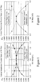
- CT 900 a Current Transducer (CT) 900 according to the prior art exploiting a dual-stage design wherein the signal induced within a first secondary windings N 1 has a corrective signal applied which is generated by second secondary winding N 2 .
- CT 900 being a dual stage CT without DC bias compensation.
- CT 900 consists of a dual stage current transformer CT R 929 containing primary winding N 0 and first and second secondary windings N 1 and N 2 respectively.
- the Current Transducer 929 primary input terminal I IN is connected to the start connection of the primary winding N 0 , while the end connection of N 0 is connected to the primary output terminal I OUT .
- An electrical shield S 930 is placed between the primary and the secondary sides and connected to a dedicated shield terminal Sh 900C.
- Winding N 1 is loaded with a precise resistance R 1 931 and second stage winding N 2 is loaded with a precise resistance R 2 932.
- the High output terminal H 900A of the Current Transducer 900 is connected to the start connection of secondary winding N 1 , while the end connection of winding N 1 is connected to the start connection of second stage winding N 2 .
- End connection of second stage winding N 2 is connected to the Low output terminal L 900B of the transducer.
- a switchable resistor i.e. a resistor switchable into the circuit or selectable between a first fixed resistance value and no resistance
- a switchable resistor is coupled between the winding N 1 and point A during manufacturing testing. Accordingly, if a variation in the signal at the H and L terminals 1000A and 1000B is measured for constant input when the switchable resistor is toggled between its two states then the polarity of the correction circuit is incorrect in assembly. Accordingly, as discussed supra in respect of Figures 1 and 2 DC currents on the input side will impact the measurements such that an incorrect AC current will be measured.
- first circuit 900A includes a Shunt R S 934 allowing a measurement of the DC current to be made thereby allowing, for example, an alarm to be triggered when the DC current exceeds a predetermined threshold.
- this DC offset may be difficult to observe and the Shunt R S 934 may limit the operating range of the measurement instrument including first circuit 900A to provide the Current Transducer.
- second circuit 900B Figure 9C
- a Hall effect sensor 935 is added to monitor the input to primary winding N 0 and provide sensing of any DC current present on the input.
- the Hall effect sensor 935 Whilst this removes the loading issue of first circuit 900A the Hall effect sensor 935 induces an inherent offset that must be accounted for and corrected for. Depending upon conductor design to the primary winding N 0 a configuration such as presented within the prior art of Seitz in US Patent 4,749,939 may be employed for example. Rather than a Hall effect sensor 935 a Flux Gate Detector (FGD) may be employed but these have the drawback that they operate with AC signals themselves, typically at 700-800Hz and thereby generate noise within the second circuit 900B.
- FGD Flux Gate Detector
- first and second circuit schematics 1000A and 1000B depicting variants of the Current Transducer (CT) according to an embodiment of the invention.
- the CT now consists of a dual stage current transformer CT R 1050A containing primary winding N 0 and first and second secondary windings N 1 and N 2 respectively together with an electrical shield S 930 placed between the primary and the secondary sides and connected to a dedicated shield terminal Sh 900C.
- First secondary winding N 1 is loaded with a precise resistance R 1 931 and second secondary winding N 2 is loaded with a precise resistance R 2 932.
- the High output terminal H 900A of the Current Transducer 1000A is connected to the start connection of secondary winding N 1 , while the end connection of winding N 1 is connected to the start connection of second stage winding N 2 . End connection of second stage winding N 2 is connected to the Low output terminal L 900B of the transducer. Accordingly, current passing through the primary winding N 0 produces a proportional voltage between output terminals H 900A and L 900B wherein the winding N 1 / precise resistance R 1 931 combination provides a correction current applied to that generated by second stage winding N 2 / precise resistance R 2 932.
- first circuit 1000A unlike CT R 929in Figure 9A , the CT R 1050A now has a Hall sensor 910 embedded within it which couples via Magnetic Field (MF) 1040A to Processing Circuit 1020 which also receives the output from the modified CT R 929. Accordingly, Processing Circuit 1020 may determine in some embodiments of the invention that the DC current is beyond a threshold established in dependence, for example, upon the magnitude of the AC current and the desired accuracy of the AC current reading. Accordingly, a measurement instrument may allow coarse low accuracy measurements on poorly conditioned input signals but prevent high accuracy measurements until the input signal has been conditioned to the required degree.
- MF Magnetic Field
- second circuit 1000B ( Figure 10B ), unlike the CT R 929 in Figures 9A through 9C and CT R 1050A in Figures 10A , the CT R 1050B now has a Hall sensor 1010 and a tertiary winding 1070.
- the Hall sensor 1010 is embedded within the CT R 1050B and couples via Magnetic Field (MF) 1040A to Processing Circuit 1030 which also receives the output from the modified CT R 1050B. Accordingly, Processing Circuit 1020 generates a correction current which is coupled to a tertiary winding 1070 with N 3 turns also coupled to the CT R 1050B.
- MF Magnetic Field
- the Processing Circuit 1030 now generates a current in dependence upon the measured DC field from Hall sensor 1010 and number of turns N 3 in order to generate within the CT R 1050B a field negating or reducing the DC field present within the CTR 1050B as a result of the conditioning or lack of conditioning applied to the input signal being analyzed.
- FIG. 10C there is a third circuit 1000C which is very similar to second circuit 1000B except that in addition to the tertiary winding N 3 coupled to the CT R 1050C there is a quaternary winding N 4 coupled together with the second secondary winding N 2 , these being upon a different core of the Current Transducer to that of the first secondary winding N 1 and tertiary winding N 3 .
- Tertiary winding N 3 and quaternary winding N 4 provide Correction Winding 1 1070 and Correction Winding 2 1060 for the two cores of the Current Transducer. Accordingly, corrective magnetic fields may be induced if necessary in multiple cores of a Current Transducer.
- the Hall sensor 1010 may be embedded into one core of a plurality of cores or alternatively multiple Hall sensors 1010 may be embedded such that a Hall sensor 1010 is disposed within each core of the Current Transducer or a predetermined subset of the cores of the Current Transducer.
- first image 1100A depicts the CT sequentially stripped from the outermost layer towards the centre whilst second image 1100B depicts a three dimensional quarter-cut sectional view with first to fifth tape layers 1130A through 1130E respectively and shielding 1160.
- CT comprises first and second cores 1110 and 1120 respectively.
- First core 1110 has embedded within it Hall sensor 1180.
- Second core 1120 then has first tape layer 1130A separating the first winding 1140 from it which is then overwound with second tape layer 1130B.
- first and second cores 1110 and 1120 with their respective surrounding layers are then overwound with third tape layer 1130C.
- third tape layer 1130C second winding 1150 is wound around both the first and second cores 1110 and 1120 respectively.
- Second winding 1150 is then overwound by fourth tape layer 1130D, shielding 1160, fifth tape layer 1130E and third winding 1170.
- first winding 1140 corresponds to second secondary winding N 2 of Figure 10A
- second winding 1150 corresponds to first secondary winding N 1 of Figure 10A
- third winding 1170 corresponds to the primary winding N 0 of Figure 10A .
- a second shielding may be disposed between the first and second windings 1140 and 1150 respectively such as between second and third tape layers 1130B and 1130C respectively.
- Second image 1100B depicts a three dimensional quarter-cut sectional view with first to fifth tape layers 1130A through 1130E respectively and shielding 1160 removed thereby showing how the first to third windings 1140, 1150 and 1170 respectively are wound around the closed magnetic elements forming the first and second cores 1110 and 1120 respectively. Also depicted within first core 1110 is Hall sensor 1180, for example, within a slot machined within the closed magnetic element forming first core 1110.
- the number of windings for each of the first to third windings 1140, 1150, and 1170 respectively and geometries of the first and second cores 1110 and 1120 respectively may be adjusted according to the electrical voltage, current and power of the signal being measured and design of the Asynchronous Power Measurement System within which the Current Transducer forms part. Accordingly, a Hall sensor such as described supra in respect of Figure 6 , and other variants not depicted, may be inserted into the first core 1110 as depicted or alternatively second core 1120 in order to provide the determination and / or management of a DC field within the Current Transducer. Optionally, multiple Hall sensors 1180 may be embedded into one or more cores.
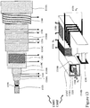
- first image 1200C depicts the CT sequentially stripped from the outermost layer towards the centre whilst second image 1200D depicts a three dimensional quarter-cut sectional view with first to fifth tape layers 1230A through 1230E respectively and shielding 1260.
- the CT comprises first, second, and third cores 1210A, 1220, and 1210B respectively.
- Second core 1220 then has first tape layer 1230A separating the first winding 1240 from it which is then overwound with second tape layer 1230B.
- first, second, and third cores 1210A, 1220, and 1210B respectively with their respective surrounding layers are then overwound with third tape layer 1230C.
- second winding 1250 is wound around first, second, and third cores 1210A, 1220, and 1210B respectively.
- Second winding 1250 is then overwound by fourth tape layer 1230D, shielding 1260, fifth tape layer 1230E and third winding 1270.
- first winding 1240 corresponds to second secondary winding N 2 of Figure 10
- second winding 1250 corresponds to first secondary winding N 1 of Figure 10
- third winding 1270 corresponds to the primary winding N 0 of Figure 10 .
- a second shielding may be disposed between the first and second windings 1240 and 1250 respectively such as between second and third tape layers 1230B and 1230C respectively.
- Hall sensor 1280 Embedded within third core 1210B is Hall sensor 1280.
- Second image 1200D depicts a three dimensional quarter-cut sectional view with first to fifth tape layers 1230A through 1230E respectively and shielding 1260 removed thereby showing how the first to third windings 1240, 1250 and 1270 respectively are wound around the closed magnetic elements forming the first, second, and third cores 1210A, 1220, and 1210B respectively. Also depicted within second image 1200D is Hall sensor 1280 which may be inserted into a slot machined within the third core 1210B.
- the number of windings for each of the first to third windings 1240, 1250, and 1270 respectively and geometries of the first, second, and third cores 1210A, 1220, and 1210B respectively may be adjusted according to the electrical voltage, current and power of the signal being measured and design of the Asynchronous Power Measurement System within which the Current Transducer forms part. Accordingly, a Hall sensor 1280 such as described supra in respect of Figures 6 , and other variants not depicted, A through 6C and Figures 11A through 11C may be inserted into the first, or the third core 1310A, or 1310B in order to provide the determination and / or management of a DC field within the Current Transducer.
- first image 1300E depicts the CT sequentially stripped from the outermost layer towards the centre whilst second image 1300F depicts a three dimensional quarter-cut sectional view with first to fifth tape layers 1330A through 1330E respectively and shielding 1360.
- the CT comprises a first core comprising first to fourth core elements 1310A to 1310D respectively surround a second core 1320.
- Second core 1320 then has first tape layer 1330A separating the first winding 1340 from it which is then overwound with second tape layer 1330B.
- first core and second core 1320 respectively with their respective surrounding layers are then overwound with third tape layer 1330C.
- second winding 1350 is wound around first core (first to fourth core elements 1310A to 1310D) and second core 1320.
- Second winding 1350 is then overwound by fourth tape layer 1330D, shielding 1360, fifth tape layer 1330E and third winding 1370.
- first winding 1340 corresponds to second secondary winding N 2 of Figure 10
- second winding 1350 corresponds to first secondary winding N 1 of Figure 10
- third winding 1370 corresponds to the primary winding N 0 of Figure 10 .
- a second shielding may be disposed between the first and second windings 1340 and 1350 respectively such as between second and third tape layers 1330B and 1330C respectively.
- Second image 1300F depicts a three dimensional quarter-cut sectional view with first to fifth tape layers 1330A through 1330E respectively and shielding 1360 removed thereby showing how the first to third windings 1340, 1350 and 1370 respectively are wound around the closed magnetic elements forming the first, second, and third cores 1310A, 1320, and 1310B respectively.
- the number of windings for each of the first to third windings 1340, 1350, and 1370 respectively and geometries of the first core (first to fourth core elements 1310A to 1310D) and second core 1320 respectively may be adjusted according to the electrical voltage, current and power of the signal being measured and design of the Asynchronous Power Measurement System within which the Current Transducer forms part.
- a Hall sensor 1390 as described supra in respect of Figures 6A through 6C and Figures 11A through 11C is disposed within the second core 1320 in order to provide the determination and / or management of a DC field within the Current Transducer.
- a magneto-strictive film 1380 which adjusts a dimension in respect to a magnetic field. Accordingly, the magneto-strictive film 1380 will increase / decrease in length along the axis of third first core element 1310C when orientated appropriately such that the DC resistance of a thin-film upon the surface of the third first core element 1310C or the third first core element 1310C itself varies with the DC field within the third first core element 1310C.
- magneto-strictive elements may be disposed upon each of the first to fourth first core elements 1310A through 1310D respectively, and second core 1320 respectively and coupled to a Processing Circuit for processing in order to define an action, such as an alarm or provisioning of a compensation signal such as described above in respect of Figures 11A through 11C for example.
- the magneto-strictive element 1380 may be employed in conjunction with a Hall sensor disposed within the second core 1320.
- multiple Hall sensors 1390 and magneto-strictive elements 1380 may be employed in conjunction with one another within / upon one or more magnetic cores of a Current Transformer.
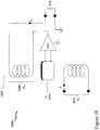
- each of the first and second fluxgate coils 1430A and 1430B respectively are coupled to fluxgate driver 1420 which provides square wave and inverted square wave signals and the output signals from the first and second fluxgate coils 1430A and 1430B respectively are coupled to a summation circuit and demodulator (DEMOD) 1410.
- Each of the DEMOD 1410 and driver 1420 are coupled to Processing Circuit 1440.
- first and second fluxgate coils 1430A and 1430B respectively are excited with equal currents but in opposite directions thereby cancelling the overall effect upon the core of CT R 1050C.
- Processing circuit 1440 may provide processing of the DEMOD 1410 in hardware and / or software or a combination thereof.
- processing circuit 1440 provides a square wave signal which comprises only odd harmonics such that effect of any magnetic field within the associated core of CT R 1050C is to generate distorted output signals with even order harmonics which are filtered from the output of DEMOD 1410 by a second order low pass filter prior to being amplified and coupled to an integrator which also receives the output from the dual-stage current transformer within CT R 1050C.
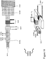
- Figure 15 depicts a two stage current transformer in first and second images 1500A and 1500B respectively according to an embodiment of the invention utilizing a third core for the DC bias detection core which when resistively connected as described in Figure 14 provides an implementation of a two stage Current Transducer with DC flux detection. Accordingly, the majority of the structures depicted in first and second images 1500A and 1500B respectively are common to the descriptions supra in respect of first and second images 1200C and 1200D in Figure 12 reflecting the third circuit 1000C in Figure 10C . However, in addition to the elements in common with these first and second images 1200C and 1200D the first and second images 1500A and 1500B also depict first and second fluxgate coils 1430A and 1430B respectively together with Compensation Coil 1 1020.
- second image 1500B the Compensation Coil 1020 is disposed around first core 1510, second core 1220, and third core 1210B as is primary winding, third winding 1270.
- Hall sensor 1280 is depicted disposed within third core 1210B. Accordingly, in first image 1500A the Compensation Coil 1020 is now formed upon the fifth tape layer 1230E upon which is wound second Shield 1530, sixth tape layer 1540, and third winding 1270.
- FIG. 16 there is depicted a current comparator in first and second images 1600A and 1600B respectively, utilizing first and second fluxgate coils 1620A and 1620B respectively to detect input and output current - turn balance wherein there is no magnetic shield between the magnetic sensor and the primary and secondary windings in contrast to prior art toroidal transformers.
- the primary coil 1630, with turns N I and secondary coil 1640, with turns N O , are wound around a single core 1610 together with first and second fluxgate sensors 1620A and 1620B respectively.
- first image 1600A the primary winding 1630, secondary winding 1640, and first and second fluxgate sensors 1620A and 1620B are wound around the single core 1610 with first tape layer 1650A. Surrounding all of these are second tape layer 1650B and shield 1660.
- the inventors have established that other magnetic shield(s) can be removed where the toroidal transformer establishes the magnetic flux from the primary winding 1630 primarily through the magnetic core 1610 which is achieved through precision control of the windings in conjunction with a high quality magnetic core and low loading from the secondary winding 1640.
- the magnetic core if the current comparator depicted within first and second images 1600A and 1600B of Figure 16 may be a dual-core or multi-core design.
- Operation of the current comparator depicted in Figure 16 exploits the magnetic core 1610 as part of a magnetic field sensing apparatus continuously magnetized back and forth from saturation in one direction to saturation in the other direction wherein the time required to drive the magnetic core from saturation to saturation is used as a measure of the magnetic field strength.
- two magnetic cores are employed in conjunction with a push-pull drive circuit for driving them from saturation to saturation thereby producing a differential output signal which beneficially reduces the coupling effects of the higher power magnetic drive circuit on the lower level output signal.
- FIGS 17A and 17B there are depicted current comparators utilizing a Hall Effect magnetic sensor 1710 embedded within the magnetic core 1720 of the current comparator to detect input and output current - turn balance wherein the prior art magnetic shield between the magnetic sensor and the primary and secondary windings has been removed.
- the current comparator comprises the Hall Effect magnetic sensor 1710 "around" which are wound the primary coil 1630 and secondary coil 1640 with the assembly then surrounded by magnetic shield 1730 which shields the current comparator from external magnetic fields.
- a magnetic circuit may be employed in conjunction with the configuration depicted in Figure 17A in order to concentrate magnetic field on the Hall effect magnetic sensor 1710 depending upon the geometry of the Hall effect magnetic sensor 1710 and the primary and second coils 1630 and 1640 respectively.
- adding such a magnetic element introduces hysteresis and impacts accuracy.
- the primary coil 1630 is formed below the Hall Effect magnetic sensor 1710 and the secondary coil 1640 is formed above it.
- the primary and secondary coils 1630 and 1640 respectively may be manufactured and characterized independent from the overall transformer.
- magnetic field concentrator(s) may be employed to concentrate the magnetic field on the Hall effect magnetic sensor 1710.
- the current comparator depicted in Figure 16 represents a design wherein the primary and secondary coil windings are implemented directly on the magnetic core.
- the current comparator depicted in Figures 17A and 17B exploits a magnetic sensor (Hall Effect) and may be implemented as a "planar" design although it may also be made as a toroid and may employ a number of Hall Effect (or other) sensors, or a single sensor with the magnetic field concentrator, for example a magnetic core with a cut slot.
- an active current to current transducer 1800 utilizing current comparator with a magnetic sensor 1810 within magnetic core 1870 and an amplification block 1820 to produce AC and DC output current in precise ratio to the input current. Accordingly, an input current I I within a primary coil 1850 induces a magnetic flux within the magnetic core 1870 which is detected by magnetic sensor 1810. The output of the magnetic sensor 1810 is amplified by amplification block 1820 and coupled to the secondary coil 1840.
- the operation of the AC-CT 1800 may be viewed as an AC amplifier with transformer feedback although the operation is significantly different in that within the AC-CT 1800 the aim, rather than compensate the input voltage with the transformed output voltage, is to compensate a first magnetic flux generated by the current flowing within the input winding with a magnetic flux generated in the output winding, such that the overall induced magnetic flux as measured by the magnetic sensor 1810 is approximately equal to zero. It would be evident to one skilled in the art that this scheme is good for both AC current transduction as well as DC transduction.
- the concept of the AC-CT 1800 is similar to that employed within DC comparator resistance bridges.
- AC-CT 1800 in common with the current transducers depicted in Figures 16 and 17 , are absent magnetic shield(s) except external to the overall assembly in order to protect the current transducers from external magnetic fields only.
- external magnetic shields are not essential from the conceptual viewpoint although they will be beneficial in reducing external electromagnetic interference fields do lower the "noise" level of the implementations.
- the transformer may be shell form or a combination of core and shell forms.
- Shell form designs may be more prevalent than core form designs for distribution transformer applications due to the relative ease in stacking the core around the winding coils.
- Core form designs tend to, as a general rule, be more economical, and therefore more prevalent, than shell form designs for high voltage power transformer applications at the lower end of their voltage and power rating ranges.
- shell form transformers tend to be more prevalent.
- Shell form design tends to be preferred for extra high voltage and higher MVA applications because, though more labor intensive to manufacture, shell form transformers are characterized as having inherently better kVA-to-weight ratio, better short-circuit strength characteristics and higher immunity to transit damage.
- embodiments of the invention may be applied to core form, shell form, and combination core-shell form transformers.
- the Processing Circuit depicted within Figures 11A through 11C may digitize the measured AC current and apply one or more corrections based upon one or more corrective algorithms to the digitized AC current based upon characterisation of these one or more surfaces.
- Such algorithms may be common to all measurement systems exploiting common coefficients or may be common algorithms exploiting coefficients derived from a characterisation of the Current Transducer wherein the derived coefficients are stored within a memory associated with the Processing Circuit.
- Implementation of the techniques, blocks, steps and means described above may be done in various ways. For example, these techniques, blocks, steps and means may be implemented in hardware, software, or a combination thereof.
- the processing units may be implemented within one or more application specific integrated circuits (ASICs), digital signal processors (DSPs), digital signal processing devices (DSPDs), programmable logic devices (PLDs), field programmable gate arrays (FPGAs), processors, controllers, micro-controllers, microprocessors, other electronic units designed to perform the functions described above and/or a combination thereof.
- ASICs application specific integrated circuits
- DSPs digital signal processors
- DSPDs digital signal processing devices
- PLDs programmable logic devices
- FPGAs field programmable gate arrays
- processors controllers, micro-controllers, microprocessors, other electronic units designed to perform the functions described above and/or a combination thereof.
Landscapes
- Engineering & Computer Science (AREA)
- Power Engineering (AREA)
- Physics & Mathematics (AREA)
- General Physics & Mathematics (AREA)
- Measuring Instrument Details And Bridges, And Automatic Balancing Devices (AREA)
- Measurement Of Current Or Voltage (AREA)
Claims (11)
- Verfahren zur Verbesserung der Wechselstromgenauigkeit eines zweistufigen Transformators (CTR), wobei der zweistufige Transformator (CTR) eine Primärwicklung (N0), eine erste Sekundärwicklung (N1) und eine zweite Sekundärwicklung (N2) umfasst, wobei das Verfahren die Schritte umfasst:Messen eines Gleichstromsignals, wobei das Gleichstromsignal abhängig von einem Gleichstromaspekt eines Signals erzeugt wird;Messen eines Wechselstromsignals, wobei das Wechselstromsignal abhängig von einem Wechselstromaspekt des Signals erzeugt wird; undErzeugen einer korrigierten Messung des gemessenen Wechselstromsignals,dadurch gekennzeichnet, dass die erste Sekundärwicklung (N1) mit einem Widerstand (R1) belastet ist und die zweite Sekundärwicklung (N2) mit einem Widerstand (R2) belastet ist, wobei ein Anschluss mit hohem Ausgangssignal (H 900A) des zweistufigen Transformators (CTR) mit einer Anfangsverbindung der ersten Sekundärwicklung (N1) verbunden ist, während eine Endverbindung der ersten Sekundärwicklung (N1) mit einer Anfangsverbindung der zweiten Sekundärwicklung (N2) verbunden ist, und eine Endverbindung der zweiten Sekundärwicklung (N2) mit einem Anschluss mit niedrigem Ausgangssignal (L 900B) des zweistufigen Transformators (CTR) verbunden ist, wobei das Verfahren den weiteren Schritt des Bereitstellens eines Korrekturstroms von der Kombination aus der ersten Sekundärwicklung (N1) und dem Widerstand (R1) zu demjenigen umfasst, der durch die Kombination aus der zweiten Sekundärwicklung (N2) und dem Widerstand (R2) erzeugt wird.
- Verfahren nach Anspruch 1, bei dem
das Messen des Gleichstromsignals mindestens eines von:Anordnen eines Magnetfeldsensors innerhalb eines Kerns des zweistufigen Transformators (CTR) für das Wechselstromsignal; undAnordnen eines Magnetfeldsensors auf einer Oberfläche des zweistufigen Transformators (CTR) für das Wechselstromsignal umfasst. - Verfahren nach Anspruch 1, bei dem
das Erzeugen einer korrigierten Messung des gemessenen Wechselstromsignals mindestens eines von:Anwenden mindestens einer Korrektur einer Mehrzahl von Korrekturen auf das gemessene Wechselstromsignal;Anwenden eines Magnetfelds auf einen vorgegebenen Abschnitt des zweistufigen Transformators (CTR), der einen Teil der Wechselstrommessung bildet, umfasst. - Verfahren nach Anspruch 3, bei dem
die Korrektur einer Mehrzahl von Korrekturen eine vorgegebene mathematische Funktion mit Koeffizienten nutzt, die mindestens eines von generisch für alle zweistufigen Transformatoren (CTR) und spezifisch für den zweistufigen Transformator (CTR) ausgebildet sind. - Verfahren nach Anspruch 3, bei dem
das Anwenden eines Magnetfelds auf einen vorgegebenen Abschnitt des zweistufigen Transformators (CTR), der einen Teil der Wechselstrommessung bildet, das Bereitstellen des Magnetfelds für mindestens einen desselben Magnetkerns und eines anderen Magnetkerns des zweistufigen Transformators (CTR) umfasst. - Verfahren nach Anspruch 1, ferner umfassend:
mindestens eines von:Verwenden eines Gleichstrommagnetsensors und einer Flusskompensation im Zusammenhang mit dem zweistufigen Transformator (CTR), der bei der Messung des Wechselstromsignals verwendet wird, wobei der zweistufige Transformator (CTR) Widerstände zum Hinzufügen von Spannungen anstatt des Hinzufügens von Strömen nutzt;
undIntegrieren eines Ausgangssignals von einem Magnetsensor, der innerhalb eines Magnetkerns einer Mehrzahl von Magnetkernen innerhalb des zweistufigen Transformators (CTR), der bei der Messung des Wechselstromsignals verwendet wird, angeordnet ist, wodurch ein Betreiben des Magnetsensors mit geringen Wechselstromflusskomponenten und einem verbesserten Wechselstrom zu Gleichstrom-Signalverhältnis ermöglicht wird. - Vorrichtung, umfassend:einen zweistufigen Transformator (CTR), der eine Mehrzahl von Magnetkernen, eine Primärwicklung (N0), eine erste Sekundärwicklung (N1) und eine zweite Sekundärwicklung (N2) umfasst;einen ersten Widerstand (R1), der zum Erzeugen einer ersten Spannung über der ersten Sekundärwicklung (N1) gekoppelt ist;einen zweiten Widerstand (R2), der über der zweiten Sekundärwicklung (N2) gekoppelt ist;einen Gleichstrommagnetsensor (1010), der mit einem ersten Magnetkern der Mehrzahl von Magnetkernen zum Erzeugen eines Signals gekoppelt ist, das proportional zu einem Gleichstrommagnetfeld innerhalb des zweistufigen Transformators (CTR) ist; undeine Flusskompensationswicklung (1070), die mit einem zweiten Magnetkern der Mehrzahl von Magnetkernen zum Erzeugen eines Magnetflusses zum Vermindern des Gleichstrommagnetfelds innerhalb des zweistufigen Transformators (CTR) gekoppelt ist;dadurch gekennzeichnet, dass der zweite Widerstand (R2), der über der zweiten Sekundärwicklung (N2) gekoppelt ist, in Reihe mit dem ersten Widerstand (R1) angeordnet ist, so dass der ersten Spannung eine Kompensationsspannung hinzugefügt wird, wobei ein Anschluss mit hohem Ausgangssignal (H 900A) des zweistufigen Transformators (CTR) mit einer Anfangsverbindung der ersten Sekundärwicklung (N1) verbunden ist, während eine Endverbindung der ersten Sekundärwicklung (N1) mit einer Anfangsverbindung der zweiten Sekundärwicklung (N2) verbunden ist, und eine Endverbindung der zweiten Sekundärwicklung (N2) mit einem Anschluss mit niedrigem Ausgangssignal (L 900B) des zweistufigen Transformators (CTR) verbunden ist, wobei die Vorrichtung zum Bereitstellen eines Korrekturstroms von der Kombination aus der ersten Sekundärwicklung (N1) und dem Widerstand (R1) zu demjenigen ausgebildet ist, der durch die Kombination aus der zweiten Sekundärwicklung (N2) und dem Widerstand (R2) erzeugt wird.
- Vorrichtung nach Anspruch 7, ferner umfassend:
einen Verarbeitungsschaltkreis, der das Signal von dem Gleichstrommagnetsensor empfängt und ein Kompensationssignal erzeugt, das mit der Flusskompensationswicklung gekoppelt werden soll. - Vorrichtung nach Anspruch 7 oder 8, umfassend:den zweistufigen Transformator (CTR), der eine Mehrzahl von Magnetkernen (1210A, 1220, 1210B) umfasst; undden Gleichstrommagnetsensor, der mit einem dritten Magnetkern (1210B) der Mehrzahl von Magnetkernen (1210A, 1220, 1210B) zum Erzeugen eines Signals gekoppelt ist, das zu einem Gleichstrommagnetfeld innerhalb des zweistufigen Transformators (CTR) proportional ist.
- Vorrichtung nach Anspruch 9, bei der
mindestens eines der Folgenden erfüllt ist:bei der Mehrzahl von Magnetkernen (1210A, 1220, 1210B) handelt es sich um drei Magnetkerne;die Primärwicklung (N0) ist um alle drei Magnetkerne gewickelt;die erste Sekundärwicklung (N1) ist um alle drei Magnetkerne gewickelt;die zweite Sekundärwicklung (N2) ist ein Mittelkern der drei Magnetkerne; undder erste Magnetkern (1210A) der Mehrzahl von Magnetkernen (1210A, 1220, 1210B) ist ein äußerer Kern der drei Magnetkerne; unddie Ströme, die in der ersten und der zweiten Sekundärwicklung erzeugt werden, werden zum Erzeugen des Ausgangssignals von dem zweistufigen Transformator (CTR) addiert. - Vorrichtung nach Anspruch 9, umfassend:
die Flusskompensationswicklung (1020), die mit allen drei Magnetkernen (1510, 1220, 1210B) zum Erzeugen eines Magnetflusses zum Vermindern des Gleichstrommagnetfelds innerhalb des zweistufigen Transformators (CTR) abhängig von dem Magnetfeld, das durch den Gleichstrommagnetsensor (1280) erfasst wird, gekoppelt ist.
Applications Claiming Priority (1)
| Application Number | Priority Date | Filing Date | Title |
|---|---|---|---|
| US201361893415P | 2013-10-21 | 2013-10-21 |
Publications (2)
| Publication Number | Publication Date |
|---|---|
| EP2878962A1 EP2878962A1 (de) | 2015-06-03 |
| EP2878962B1 true EP2878962B1 (de) | 2020-03-18 |
Family
ID=52577583
Family Applications (1)
| Application Number | Title | Priority Date | Filing Date |
|---|---|---|---|
| EP14003584.1A Active EP2878962B1 (de) | 2013-10-21 | 2014-10-21 | Verfahren und Systeme im Zusammenhang mit Wechselstrommessungen |
Country Status (3)
| Country | Link |
|---|---|
| US (2) | US9829512B2 (de) |
| EP (1) | EP2878962B1 (de) |
| CA (1) | CA2868663C (de) |
Families Citing this family (32)
| Publication number | Priority date | Publication date | Assignee | Title |
|---|---|---|---|---|
| US9829512B2 (en) | 2013-10-21 | 2017-11-28 | Guildline Instruments Limited | Methods and systems relating to AC current measurements |
| CN106324539B (zh) * | 2015-07-01 | 2019-06-14 | 中国电力科学研究院 | 一种高精度电流比较仪 |
| JP6579851B2 (ja) * | 2015-07-31 | 2019-09-25 | 三菱電機株式会社 | 電力管理システム |
| US9618541B1 (en) * | 2016-04-20 | 2017-04-11 | Neilsen-Kuljian, Inc. | Apparatus, method and device for sensing DC currents |
| US10605832B2 (en) * | 2016-11-11 | 2020-03-31 | Fluke Corporation | Sensor subsystems for non-contact voltage measurement devices |
| FR3060757B1 (fr) * | 2016-12-19 | 2020-11-06 | Safran Electronics & Defense | Capteur de courant a vanne de flux |
| CN108107396B (zh) * | 2017-08-01 | 2024-06-04 | 国网江西省电力公司电力科学研究院 | 一种补偿泄漏电流的电流互感器误差检测装置 |
| CN108490239B (zh) * | 2018-03-16 | 2023-10-24 | 华中科技大学 | 一种暂态电流测量装置 |
| CN108594155B (zh) * | 2018-04-28 | 2024-03-01 | 国网江苏省电力有限公司电力科学研究院 | 一种电能表电流互感器过饱和特性参数测量系统及方法 |
| CN108594919B (zh) * | 2018-05-07 | 2020-12-22 | 深圳合立源科技有限公司 | 一种基于检测霍尔电流传感器反馈的电流控制电路 |
| CN108562774B (zh) * | 2018-06-21 | 2021-05-07 | 山东航天电子技术研究所 | 一种小型金属外壳集磁式霍尔电流传感器 |
| DE102018213203A1 (de) * | 2018-08-07 | 2020-02-13 | Siemens Aktiengesellschaft | Strommesswandlereinrichtung mit Strommesswandler und Verfahren zum Kalibrieren eines Strommesswandlers |
| KR102036027B1 (ko) * | 2018-09-21 | 2019-10-24 | 한국생산기술연구원 | 고전압 레벨 변환기 |
| JP7204453B2 (ja) * | 2018-11-30 | 2023-01-16 | 株式会社東芝 | 電流検出装置 |
| JP7258526B2 (ja) * | 2018-11-30 | 2023-04-17 | 株式会社東芝 | 電流検出装置 |
| DE102018130690B3 (de) * | 2018-12-03 | 2020-03-26 | Bender Gmbh & Co. Kg | Magnetfeld-Messvorrichtung und Verfahren zur Erfassung eines Lokalisierungsstroms in einem verzweigten Wechselstrom-Stromversorgungssystem |
| JP7309390B2 (ja) * | 2019-03-13 | 2023-07-18 | 株式会社東芝 | 電流検出装置 |
| US11705275B2 (en) * | 2019-12-02 | 2023-07-18 | Panoramic Power Ltd. | Self calibration by double signal sampling |
| US11002804B1 (en) * | 2020-01-14 | 2021-05-11 | Honeywell International Inc. | Magnetic field sensor compensation methods and systems |
| US12235291B2 (en) * | 2020-04-11 | 2025-02-25 | Tektronix, Inc. | Current shunt probe |
| CN111665384B (zh) * | 2020-05-22 | 2022-07-29 | 哈尔滨工业大学 | 一种全数字磁通门型电流传感器及其噪声抑制方法 |
| EP4123317A1 (de) * | 2021-07-20 | 2023-01-25 | LEM International SA | Fluxgate-wandler zur strommessung |
| US12163983B2 (en) | 2021-08-23 | 2024-12-10 | Allegro Microsystems, Llc | Packaged current sensor integrated circuit |
| US11768229B2 (en) * | 2021-08-23 | 2023-09-26 | Allegro Microsystems, Llc | Packaged current sensor integrated circuit |
| US12487254B2 (en) | 2021-08-23 | 2025-12-02 | Allegro Microsystems, Llc | Packaged current sensor integrated circuit |
| WO2023167096A1 (ja) * | 2022-03-03 | 2023-09-07 | 旭化成エレクトロニクス株式会社 | 電流センサ、及び電流検出方法 |
| CN114859097B (zh) * | 2022-06-07 | 2025-06-24 | 北京普瑞姆赛斯科技有限公司 | 一种电流传感器及电流检测方法 |
| US12287358B2 (en) * | 2022-09-16 | 2025-04-29 | GM Global Technology Operations LLC | Current sensing apparatus |
| CN116106614B (zh) * | 2022-11-03 | 2025-09-23 | 北京四方继保自动化股份有限公司 | 一种基于双磁芯互补原理的变压器过电压传感器 |
| JP7568773B1 (ja) * | 2023-03-31 | 2024-10-16 | 本田技研工業株式会社 | 電流測定装置および電流測定方法 |
| CN116435078B (zh) * | 2023-06-05 | 2023-08-22 | 烟台东方威思顿电气有限公司 | 基于双环路的穿心式电流隔离互感器 |
| US12493057B2 (en) | 2023-11-17 | 2025-12-09 | Allegro Microsystems, Llc | Current sensor integrated circuit |
Citations (1)
| Publication number | Priority date | Publication date | Assignee | Title |
|---|---|---|---|---|
| US7309980B2 (en) * | 2006-05-08 | 2007-12-18 | Tektronix, Inc. | Current sensing circuit for use in a current measurement probe |
Family Cites Families (10)
| Publication number | Priority date | Publication date | Assignee | Title |
|---|---|---|---|---|
| US4613841A (en) * | 1983-11-30 | 1986-09-23 | General Electric Company | Integrated transformer and inductor |
| CH670004A5 (de) | 1986-02-10 | 1989-04-28 | Landis & Gyr Ag | |
| EP0356248B1 (de) * | 1988-08-24 | 1995-09-06 | Liaisons Electroniques-Mecaniques Lem S.A. | Stromsensor |
| CH684216A5 (fr) * | 1991-02-15 | 1994-07-29 | Lem Liaisons Electron Mec | Dispositif de mesure de courants. |
| KR20050007339A (ko) * | 2002-04-29 | 2005-01-17 | 앰비언트 코오퍼레이션 | 고 전류 유도성 커플러 및 전력선용 계기용 변류기 |
| US7348845B2 (en) * | 2005-05-19 | 2008-03-25 | Roberto Michele Giovannotto | System and method for employing variable magnetic flux bias in an amplifier |
| US7834613B2 (en) * | 2007-10-30 | 2010-11-16 | Power-One, Inc. | Isolated current to voltage, voltage to voltage converter |
| US7876086B2 (en) * | 2008-02-28 | 2011-01-25 | International Components Corporation | Current measuring device for measuring the electrical current flowing in an electrical conductor electrically isolated from the current measuring device |
| US8421444B2 (en) * | 2009-12-31 | 2013-04-16 | Schneider Electric USA, Inc. | Compact, two stage, zero flux electronically compensated current or voltage transducer employing dual magnetic cores having substantially dissimilar magnetic characteristics |
| US9829512B2 (en) | 2013-10-21 | 2017-11-28 | Guildline Instruments Limited | Methods and systems relating to AC current measurements |
-
2014
- 2014-10-20 US US14/518,602 patent/US9829512B2/en active Active
- 2014-10-20 CA CA2868663A patent/CA2868663C/en active Active
- 2014-10-21 EP EP14003584.1A patent/EP2878962B1/de active Active
-
2016
- 2016-07-26 US US15/220,058 patent/US10139432B2/en active Active
Patent Citations (1)
| Publication number | Priority date | Publication date | Assignee | Title |
|---|---|---|---|---|
| US7309980B2 (en) * | 2006-05-08 | 2007-12-18 | Tektronix, Inc. | Current sensing circuit for use in a current measurement probe |
Non-Patent Citations (1)
| Title |
|---|
| WEST J L ET AL: "AN IMPROVED TWO-STAGE CURRENT TRANSFORMER", IEEE TRANSACTIONS ON INSTRUMENTATION AND MEASUREMENT, IEEE SERVICE CENTER, PISCATAWAY, NJ, US, vol. 40, no. 3, 1 June 1991 (1991-06-01), pages 633 - 635, XP000259719, ISSN: 0018-9456, DOI: 10.1109/19.87032 * |
Also Published As
| Publication number | Publication date |
|---|---|
| US20150108967A1 (en) | 2015-04-23 |
| US20160334443A1 (en) | 2016-11-17 |
| US10139432B2 (en) | 2018-11-27 |
| EP2878962A1 (de) | 2015-06-03 |
| CA2868663C (en) | 2016-11-08 |
| US9829512B2 (en) | 2017-11-28 |
| CA2868663A1 (en) | 2015-04-21 |
Similar Documents
| Publication | Publication Date | Title |
|---|---|---|
| EP2878962B1 (de) | Verfahren und Systeme im Zusammenhang mit Wechselstrommessungen | |
| Ramboz | Machinable Rogowski coil, design, and calibration | |
| US10078102B2 (en) | Methods and devices for AC current sources, precision current transducers and detectors | |
| US7279884B2 (en) | Temperature compensated and self-calibrated current sensor using reference magnetic field | |
| US11705275B2 (en) | Self calibration by double signal sampling | |
| CN1243248C (zh) | 一种电流传感器 | |
| Xie et al. | Giant-magnetoresistance-based galvanically isolated voltage and current measurements | |
| CN112362941B (zh) | 一种环形电流互感器及其测量电流的方法 | |
| JP2025524258A (ja) | 交直流のマルチエアギャップ磁気抵抗電流センサおよび電流測定方法 | |
| CN115078806B (zh) | 一种功率模块开关电流宽频集成测量方法 | |
| Delahaye et al. | Accurate AC measurements of standard resistors between 1 and 20 Hz | |
| CN115541960A (zh) | 磁电阻传感器、芯片及芯片的制备方法 | |
| RU2192020C1 (ru) | Устройство для поверки измерительных трансформаторов тока | |
| Xiaohua et al. | Improved performance Rogowski coils for power system | |
| EP1923709B1 (de) | Aktive lineare Stromwandler | |
| CN104897944A (zh) | 一种测量50a以上直流电流的方法 | |
| Ranasingh et al. | Novel Winding Arrangements for Measuring High-Amplitude Current With Interference Error Compensation Scheme | |
| KR100724101B1 (ko) | 공심코어를 사용한 교류전류 센서 | |
| CN116829962A (zh) | 二合一线圈电流传感器 | |
| Mikhaylov | Influence of external magnetic fields on measurement errors by induction current transformers | |
| Li et al. | Tunnel magnetoresistive sensor design and applications for current measurement | |
| Slomovitz et al. | Two-stage current transformer with electronic compensation | |
| Zhou et al. | AUTOMATIC MEASUREMENT AND CALIBRATION OF DC CURRENT RATIO ERROR | |
| BR102023016316A2 (pt) | Transdutor de corrente alternada e contínua para tensão ou corrente baseado em eletrônica de potência com blindagem eletrostática |
Legal Events
| Date | Code | Title | Description |
|---|---|---|---|
| PUAI | Public reference made under article 153(3) epc to a published international application that has entered the european phase |
Free format text: ORIGINAL CODE: 0009012 |
|
| 17P | Request for examination filed |
Effective date: 20141021 |
|
| AK | Designated contracting states |
Kind code of ref document: A1 Designated state(s): AL AT BE BG CH CY CZ DE DK EE ES FI FR GB GR HR HU IE IS IT LI LT LU LV MC MK MT NL NO PL PT RO RS SE SI SK SM TR |
|
| AX | Request for extension of the european patent |
Extension state: BA ME |
|
| R17P | Request for examination filed (corrected) |
Effective date: 20151203 |
|
| RBV | Designated contracting states (corrected) |
Designated state(s): AL AT BE BG CH CY CZ DE DK EE ES FI FR GB GR HR HU IE IS IT LI LT LU LV MC MK MT NL NO PL PT RO RS SE SI SK SM TR |
|
| STAA | Information on the status of an ep patent application or granted ep patent |
Free format text: STATUS: EXAMINATION IS IN PROGRESS |
|
| 17Q | First examination report despatched |
Effective date: 20180619 |
|
| GRAP | Despatch of communication of intention to grant a patent |
Free format text: ORIGINAL CODE: EPIDOSNIGR1 |
|
| STAA | Information on the status of an ep patent application or granted ep patent |
Free format text: STATUS: GRANT OF PATENT IS INTENDED |
|
| RIC1 | Information provided on ipc code assigned before grant |
Ipc: G01R 15/18 20060101AFI20190821BHEP Ipc: G01R 19/00 20060101ALI20190821BHEP |
|
| GRAJ | Information related to disapproval of communication of intention to grant by the applicant or resumption of examination proceedings by the epo deleted |
Free format text: ORIGINAL CODE: EPIDOSDIGR1 |
|
| STAA | Information on the status of an ep patent application or granted ep patent |
Free format text: STATUS: EXAMINATION IS IN PROGRESS |
|
| INTG | Intention to grant announced |
Effective date: 20190924 |
|
| GRAP | Despatch of communication of intention to grant a patent |
Free format text: ORIGINAL CODE: EPIDOSNIGR1 |
|
| STAA | Information on the status of an ep patent application or granted ep patent |
Free format text: STATUS: GRANT OF PATENT IS INTENDED |
|
| INTC | Intention to grant announced (deleted) | ||
| INTG | Intention to grant announced |
Effective date: 20191107 |
|
| GRAS | Grant fee paid |
Free format text: ORIGINAL CODE: EPIDOSNIGR3 |
|
| GRAA | (expected) grant |
Free format text: ORIGINAL CODE: 0009210 |
|
| STAA | Information on the status of an ep patent application or granted ep patent |
Free format text: STATUS: THE PATENT HAS BEEN GRANTED |
|
| AK | Designated contracting states |
Kind code of ref document: B1 Designated state(s): AL AT BE BG CH CY CZ DE DK EE ES FI FR GB GR HR HU IE IS IT LI LT LU LV MC MK MT NL NO PL PT RO RS SE SI SK SM TR |
|
| REG | Reference to a national code |
Ref country code: GB Ref legal event code: FG4D |
|
| REG | Reference to a national code |
Ref country code: DE Ref legal event code: R096 Ref document number: 602014062421 Country of ref document: DE |
|
| REG | Reference to a national code |
Ref country code: AT Ref legal event code: REF Ref document number: 1246528 Country of ref document: AT Kind code of ref document: T Effective date: 20200415 Ref country code: IE Ref legal event code: FG4D |
|
| PG25 | Lapsed in a contracting state [announced via postgrant information from national office to epo] |
Ref country code: RS Free format text: LAPSE BECAUSE OF FAILURE TO SUBMIT A TRANSLATION OF THE DESCRIPTION OR TO PAY THE FEE WITHIN THE PRESCRIBED TIME-LIMIT Effective date: 20200318 Ref country code: FI Free format text: LAPSE BECAUSE OF FAILURE TO SUBMIT A TRANSLATION OF THE DESCRIPTION OR TO PAY THE FEE WITHIN THE PRESCRIBED TIME-LIMIT Effective date: 20200318 Ref country code: NO Free format text: LAPSE BECAUSE OF FAILURE TO SUBMIT A TRANSLATION OF THE DESCRIPTION OR TO PAY THE FEE WITHIN THE PRESCRIBED TIME-LIMIT Effective date: 20200618 |
|
| REG | Reference to a national code |
Ref country code: NL Ref legal event code: MP Effective date: 20200318 |
|
| PG25 | Lapsed in a contracting state [announced via postgrant information from national office to epo] |
Ref country code: BG Free format text: LAPSE BECAUSE OF FAILURE TO SUBMIT A TRANSLATION OF THE DESCRIPTION OR TO PAY THE FEE WITHIN THE PRESCRIBED TIME-LIMIT Effective date: 20200618 Ref country code: GR Free format text: LAPSE BECAUSE OF FAILURE TO SUBMIT A TRANSLATION OF THE DESCRIPTION OR TO PAY THE FEE WITHIN THE PRESCRIBED TIME-LIMIT Effective date: 20200619 Ref country code: HR Free format text: LAPSE BECAUSE OF FAILURE TO SUBMIT A TRANSLATION OF THE DESCRIPTION OR TO PAY THE FEE WITHIN THE PRESCRIBED TIME-LIMIT Effective date: 20200318 Ref country code: SE Free format text: LAPSE BECAUSE OF FAILURE TO SUBMIT A TRANSLATION OF THE DESCRIPTION OR TO PAY THE FEE WITHIN THE PRESCRIBED TIME-LIMIT Effective date: 20200318 Ref country code: LV Free format text: LAPSE BECAUSE OF FAILURE TO SUBMIT A TRANSLATION OF THE DESCRIPTION OR TO PAY THE FEE WITHIN THE PRESCRIBED TIME-LIMIT Effective date: 20200318 |
|
| REG | Reference to a national code |
Ref country code: LT Ref legal event code: MG4D |
|
| PG25 | Lapsed in a contracting state [announced via postgrant information from national office to epo] |
Ref country code: NL Free format text: LAPSE BECAUSE OF FAILURE TO SUBMIT A TRANSLATION OF THE DESCRIPTION OR TO PAY THE FEE WITHIN THE PRESCRIBED TIME-LIMIT Effective date: 20200318 |
|
| PG25 | Lapsed in a contracting state [announced via postgrant information from national office to epo] |
Ref country code: PT Free format text: LAPSE BECAUSE OF FAILURE TO SUBMIT A TRANSLATION OF THE DESCRIPTION OR TO PAY THE FEE WITHIN THE PRESCRIBED TIME-LIMIT Effective date: 20200812 Ref country code: SM Free format text: LAPSE BECAUSE OF FAILURE TO SUBMIT A TRANSLATION OF THE DESCRIPTION OR TO PAY THE FEE WITHIN THE PRESCRIBED TIME-LIMIT Effective date: 20200318 Ref country code: EE Free format text: LAPSE BECAUSE OF FAILURE TO SUBMIT A TRANSLATION OF THE DESCRIPTION OR TO PAY THE FEE WITHIN THE PRESCRIBED TIME-LIMIT Effective date: 20200318 Ref country code: SK Free format text: LAPSE BECAUSE OF FAILURE TO SUBMIT A TRANSLATION OF THE DESCRIPTION OR TO PAY THE FEE WITHIN THE PRESCRIBED TIME-LIMIT Effective date: 20200318 Ref country code: RO Free format text: LAPSE BECAUSE OF FAILURE TO SUBMIT A TRANSLATION OF THE DESCRIPTION OR TO PAY THE FEE WITHIN THE PRESCRIBED TIME-LIMIT Effective date: 20200318 Ref country code: IS Free format text: LAPSE BECAUSE OF FAILURE TO SUBMIT A TRANSLATION OF THE DESCRIPTION OR TO PAY THE FEE WITHIN THE PRESCRIBED TIME-LIMIT Effective date: 20200718 Ref country code: CZ Free format text: LAPSE BECAUSE OF FAILURE TO SUBMIT A TRANSLATION OF THE DESCRIPTION OR TO PAY THE FEE WITHIN THE PRESCRIBED TIME-LIMIT Effective date: 20200318 Ref country code: LT Free format text: LAPSE BECAUSE OF FAILURE TO SUBMIT A TRANSLATION OF THE DESCRIPTION OR TO PAY THE FEE WITHIN THE PRESCRIBED TIME-LIMIT Effective date: 20200318 |
|
| REG | Reference to a national code |
Ref country code: AT Ref legal event code: MK05 Ref document number: 1246528 Country of ref document: AT Kind code of ref document: T Effective date: 20200318 |
|
| REG | Reference to a national code |
Ref country code: DE Ref legal event code: R097 Ref document number: 602014062421 Country of ref document: DE |
|
| PLBE | No opposition filed within time limit |
Free format text: ORIGINAL CODE: 0009261 |
|
| STAA | Information on the status of an ep patent application or granted ep patent |
Free format text: STATUS: NO OPPOSITION FILED WITHIN TIME LIMIT |
|
| PG25 | Lapsed in a contracting state [announced via postgrant information from national office to epo] |
Ref country code: DK Free format text: LAPSE BECAUSE OF FAILURE TO SUBMIT A TRANSLATION OF THE DESCRIPTION OR TO PAY THE FEE WITHIN THE PRESCRIBED TIME-LIMIT Effective date: 20200318 Ref country code: IT Free format text: LAPSE BECAUSE OF FAILURE TO SUBMIT A TRANSLATION OF THE DESCRIPTION OR TO PAY THE FEE WITHIN THE PRESCRIBED TIME-LIMIT Effective date: 20200318 Ref country code: AT Free format text: LAPSE BECAUSE OF FAILURE TO SUBMIT A TRANSLATION OF THE DESCRIPTION OR TO PAY THE FEE WITHIN THE PRESCRIBED TIME-LIMIT Effective date: 20200318 Ref country code: ES Free format text: LAPSE BECAUSE OF FAILURE TO SUBMIT A TRANSLATION OF THE DESCRIPTION OR TO PAY THE FEE WITHIN THE PRESCRIBED TIME-LIMIT Effective date: 20200318 |
|
| 26N | No opposition filed |
Effective date: 20201221 |
|
| PG25 | Lapsed in a contracting state [announced via postgrant information from national office to epo] |
Ref country code: PL Free format text: LAPSE BECAUSE OF FAILURE TO SUBMIT A TRANSLATION OF THE DESCRIPTION OR TO PAY THE FEE WITHIN THE PRESCRIBED TIME-LIMIT Effective date: 20200318 |
|
| PG25 | Lapsed in a contracting state [announced via postgrant information from national office to epo] |
Ref country code: SI Free format text: LAPSE BECAUSE OF FAILURE TO SUBMIT A TRANSLATION OF THE DESCRIPTION OR TO PAY THE FEE WITHIN THE PRESCRIBED TIME-LIMIT Effective date: 20200318 |
|
| REG | Reference to a national code |
Ref country code: CH Ref legal event code: PL |
|
| PG25 | Lapsed in a contracting state [announced via postgrant information from national office to epo] |
Ref country code: LU Free format text: LAPSE BECAUSE OF NON-PAYMENT OF DUE FEES Effective date: 20201021 Ref country code: MC Free format text: LAPSE BECAUSE OF FAILURE TO SUBMIT A TRANSLATION OF THE DESCRIPTION OR TO PAY THE FEE WITHIN THE PRESCRIBED TIME-LIMIT Effective date: 20200318 |
|
| REG | Reference to a national code |
Ref country code: BE Ref legal event code: MM Effective date: 20201031 |
|
| PG25 | Lapsed in a contracting state [announced via postgrant information from national office to epo] |
Ref country code: LI Free format text: LAPSE BECAUSE OF NON-PAYMENT OF DUE FEES Effective date: 20201031 Ref country code: CH Free format text: LAPSE BECAUSE OF NON-PAYMENT OF DUE FEES Effective date: 20201031 Ref country code: BE Free format text: LAPSE BECAUSE OF NON-PAYMENT OF DUE FEES Effective date: 20201031 |
|
| PG25 | Lapsed in a contracting state [announced via postgrant information from national office to epo] |
Ref country code: IE Free format text: LAPSE BECAUSE OF NON-PAYMENT OF DUE FEES Effective date: 20201021 |
|
| PG25 | Lapsed in a contracting state [announced via postgrant information from national office to epo] |
Ref country code: TR Free format text: LAPSE BECAUSE OF FAILURE TO SUBMIT A TRANSLATION OF THE DESCRIPTION OR TO PAY THE FEE WITHIN THE PRESCRIBED TIME-LIMIT Effective date: 20200318 Ref country code: MT Free format text: LAPSE BECAUSE OF FAILURE TO SUBMIT A TRANSLATION OF THE DESCRIPTION OR TO PAY THE FEE WITHIN THE PRESCRIBED TIME-LIMIT Effective date: 20200318 Ref country code: CY Free format text: LAPSE BECAUSE OF FAILURE TO SUBMIT A TRANSLATION OF THE DESCRIPTION OR TO PAY THE FEE WITHIN THE PRESCRIBED TIME-LIMIT Effective date: 20200318 |
|
| PG25 | Lapsed in a contracting state [announced via postgrant information from national office to epo] |
Ref country code: MK Free format text: LAPSE BECAUSE OF FAILURE TO SUBMIT A TRANSLATION OF THE DESCRIPTION OR TO PAY THE FEE WITHIN THE PRESCRIBED TIME-LIMIT Effective date: 20200318 Ref country code: AL Free format text: LAPSE BECAUSE OF FAILURE TO SUBMIT A TRANSLATION OF THE DESCRIPTION OR TO PAY THE FEE WITHIN THE PRESCRIBED TIME-LIMIT Effective date: 20200318 |
|
| REG | Reference to a national code |
Ref country code: DE Ref legal event code: R082 Ref document number: 602014062421 Country of ref document: DE Representative=s name: KANDLBINDER, MARKUS, DIPL.-PHYS., DE |
|
| PGFP | Annual fee paid to national office [announced via postgrant information from national office to epo] |
Ref country code: DE Payment date: 20251216 Year of fee payment: 12 |
|
| PGFP | Annual fee paid to national office [announced via postgrant information from national office to epo] |
Ref country code: GB Payment date: 20251024 Year of fee payment: 12 |
|
| PGFP | Annual fee paid to national office [announced via postgrant information from national office to epo] |
Ref country code: FR Payment date: 20251027 Year of fee payment: 12 |