EP2880250B1 - Déflecteur activé à distance - Google Patents
Déflecteur activé à distance Download PDFInfo
- Publication number
- EP2880250B1 EP2880250B1 EP12882531.2A EP12882531A EP2880250B1 EP 2880250 B1 EP2880250 B1 EP 2880250B1 EP 12882531 A EP12882531 A EP 12882531A EP 2880250 B1 EP2880250 B1 EP 2880250B1
- Authority
- EP
- European Patent Office
- Prior art keywords
- bore
- deflector
- controller
- identity
- block junction
- Prior art date
- Legal status (The legal status is an assumption and is not a legal conclusion. Google has not performed a legal analysis and makes no representation as to the accuracy of the status listed.)
- Not-in-force
Links
Images


Classifications
-
- E—FIXED CONSTRUCTIONS
- E21—EARTH OR ROCK DRILLING; MINING
- E21B—EARTH OR ROCK DRILLING; OBTAINING OIL, GAS, WATER, SOLUBLE OR MELTABLE MATERIALS OR A SLURRY OF MINERALS FROM WELLS
- E21B23/00—Apparatus for displacing, setting, locking, releasing or removing tools, packers or the like in boreholes or wells
- E21B23/08—Introducing or running tools by fluid pressure, e.g. through-the-flow-line tool systems
- E21B23/12—Tool diverters
-
- E—FIXED CONSTRUCTIONS
- E21—EARTH OR ROCK DRILLING; MINING
- E21B—EARTH OR ROCK DRILLING; OBTAINING OIL, GAS, WATER, SOLUBLE OR MELTABLE MATERIALS OR A SLURRY OF MINERALS FROM WELLS
- E21B37/00—Methods or apparatus for cleaning boreholes or wells
-
- E—FIXED CONSTRUCTIONS
- E21—EARTH OR ROCK DRILLING; MINING
- E21B—EARTH OR ROCK DRILLING; OBTAINING OIL, GAS, WATER, SOLUBLE OR MELTABLE MATERIALS OR A SLURRY OF MINERALS FROM WELLS
- E21B41/00—Equipment or details not covered by groups E21B15/00 - E21B40/00
- E21B41/0035—Apparatus or methods for multilateral well technology, e.g. for the completion of or workover on wells with one or more lateral branches
-
- E—FIXED CONSTRUCTIONS
- E21—EARTH OR ROCK DRILLING; MINING
- E21B—EARTH OR ROCK DRILLING; OBTAINING OIL, GAS, WATER, SOLUBLE OR MELTABLE MATERIALS OR A SLURRY OF MINERALS FROM WELLS
- E21B47/00—Survey of boreholes or wells
- E21B47/12—Means for transmitting measuring-signals or control signals from the well to the surface, or from the surface to the well, e.g. for logging while drilling
- E21B47/13—Means for transmitting measuring-signals or control signals from the well to the surface, or from the surface to the well, e.g. for logging while drilling by electromagnetic energy, e.g. radio frequency
Definitions
- Hydrocarbons may be produced from wellbores drilled from the surface through a variety of producing and non-producing formations.
- the wellbore may be drilled substantially vertically or may be an offset well that is not vertical and has some amount of horizontal displacement from the surface entry point.
- a multilateral well may be drilled comprising a plurality of wellbores drilled off of a main wellbore, each of which may be referred to as a lateral wellbore. Portions of lateral wellbores may be substantially horizontal to the surface.
- wellbores may be very deep, for example extending more than 10,000 feet from the surface.
- a variety of servicing operations may be performed on a wellbore after it has been initially drilled.
- a lateral junction may be set in the wellbore at the intersection of two lateral wellbores and/or at the intersection of a lateral wellbore with the main wellbore.
- a casing string may be set and cemented in the wellbore.
- a liner may be hung in the casing string.
- the casing string may be perforated by firing a perforation gun.
- a packer may be set and a formation proximate to the wellbore may be hydraulically fractured.
- a plug may be set in the wellbore. Typically it is undesirable for debris, fines, and other material to accumulate in the wellbore.
- Fines may comprise more or less granular particles that originate from the subterranean formations drilled through or perforated.
- the debris may comprise material broken off of drill bits, material cut off casing walls, pieces of perforating guns, and other materials.
- a wellbore may be cleaned out or swept to remove fines and/or debris that have entered the wellbore.
- Those skilled in the art may readily identify additional wellbore servicing operations. In many servicing operations, a downhole tool is conveyed into the main wellbore and possibly into one or more laterals drilled off of the main wellbore and/or drilled off of a lateral wellbore.
- GB 2 318 817 discloses a method for completing a wellbore and WO 2008/068561 discloses methods and apparatus for navigating a tool downhole.
- a wellbore y-block junction comprising: a first bore channel; a second bore channel; a deflector selectable to a neutral position, to a first bore channel selected position, and to a second bore channel selected position; a radio receiver; and a controller, wherein the controller is configured to command the deflector position to one of the neutral position, the first bore channel selected position, or the second bore channel selected position based on an input from the radio receiver.
- a method of performing a wellbore service job comprising: running in a tool string into a wellbore above a first y-block junction, wherein the wellbore comprises at least a first bore and a second bore, wherein the tool string carries at least one radio frequency identity (RFID) tag on an end of the tool string; reading a first identity from the at least one radio frequency identity tag by a first controller of the first y-block junction; and directing the tool string into the first bore based on reading the first identity.
- RFID radio frequency identity
- a method of performing a wellbore service job comprising: running in a tool string into a wellbore above a first y-block junction, wherein the wellbore comprises at least a first bore and a second bore, wherein the tool string carries a first near field communication (NFC) transceiver on an end of the tool string; transmitting a command from the first near field communication transceiver to a second near field communication transceiver coupled to the first y-block junction; and directing the tool string into the first bore based on the command.
- NFC near field communication
- any use of any form of the terms “connect,” “engage,” “couple,” “attach,” or any other term describing an interaction between elements is not meant to limit the interaction to direct interaction between the elements and may also include indirect interaction between the elements described.
- the terms “including” and “comprising” are used in an open-ended fashion, and thus should be interpreted to mean “including, but not limited to ". Reference to up or down will be made for purposes of description with “up,” “upper,” “upward,” or “upstream” meaning toward the surface of the wellbore and with “down,” “lower,” “downward,” or “downstream” meaning toward the terminal end of the well, regardless of the wellbore orientation.
- zone or “pay zone” as used herein refers to separate parts of the wellbore designated for treatment or production and may refer to an entire hydrocarbon formation or separate portions of a single formation, such as horizontally and/or vertically spaced portions of the same formation.
- a y-block junction having a selectable position deflector is described.
- the y-block junction promotes downhole access to two bores, for example to a first lateral bore and to a second lateral bore.
- the y-block junction incorporates a deflector that may be positioned to one of a neutral position, a first bore channel selected position, or a second bore channel selected position.
- a bottom hole assembly that is run into the y-block junction is directed by the position deflector into the first bore.
- the deflector is positioned to the second bore channel selected position
- a bottom hole assembly that is run into the y-block junction is directed by the position deflector into the second bore.
- the y-block junction comprises a controller that commands the deflector to a position selected by logic executed by the controller.
- the deflector may be actuated by an electric motor or solenoid coupled to and commanded by the controller. Alternatively, the deflector may be actuated by motive force derived from fluid flow, under the command of the controller.
- the deflector may be actively held in position in one of the neutral position, the first bore channel selected position, or the second bore channel selected position. Alternatively, the deflector may be displaced to one of the first bore channel selected position, the second bore channel selected position, or the neutral position and may then be mechanically maintained in that position, for example by a détente or by a mechanical locking mechanism.
- the controller may command release of a mechanical locking mechanism.
- a communication device may be coupled to the bottom hole assembly.
- the controller may receive identification information or control information from the communication device coupled to the bottom hole assembly, process the identification information with controller logic, and command the deflector position based on the processing of the identification information.
- a radio frequency identity (RFID) tag is coupled to the bottom hole assembly that contains an identity.
- the controller may be preconfigured to command the deflector to a specific position when the subject RFID tag is detected proximate to the y-block junction, for example by a radio frequency identity scanner coupled to the controller.
- the bottom hole assembly may comprise a plurality of RFID tags, one or more RFID tags associated with each y-block junction.
- a single RFID tag may encode a plurality of separate identities, each separate identity associated with a different y-block junction. In this way, an arbitrary sequence of deflector positions in each of the transited y-block junctions can be commanded as the bottom hole assembly is run into the wellbore.
- the communication device may comprise a near field communication (NFC) radio transceiver.
- the NFC transceiver of the bottom hole assembly may engage in two-way communication with a NFC radio transceiver coupled to the y-block junction and to the controller.
- the NFC transceiver of the bottom hole assembly may send a message to the NFC radio transceiver coupled to the controller, where the message indicates which position to drive the deflector to.
- the y-block junction may incorporate sensors or limit switches that determine what position the deflector is in, and the controller may direct the NFC transceiver coupled to the controller to send a reply message to the NFC transceiver of the bottom hole assembly.
- the NFC transceiver of the bottom hole assembly may transmit the position information to a device located at the surface proximate the wellbore, for example to an electronic workstation or command station.
- the operators at the surface may decide to continue to run the bottom hole assembly into the wellbore or take some other action in response to the position information received from the NFC transceiver of the bottom hole assembly.
- Some systems rely upon a diameter of the bottom hole assembly. For example, a larger diameter bottom hole assembly may be excluded from a first bore and allowed into a second bore, and a smaller diameter bottom hole assembly may be preferentially directed to the first bore.
- a larger diameter bottom hole assembly may be excluded from a first bore and allowed into a second bore, and a smaller diameter bottom hole assembly may be preferentially directed to the first bore.
- using different diameter tools to select the several different laterals may become impractical.
- the selectable deflector taught herein may overcome this limitation in some wellbore environments.
- the system 10 comprises a servicing rig 16 that extends over and around a wellbore 12 that penetrates a subterranean formation 14 for the purpose of recovering hydrocarbons, storing hydrocarbons, disposing of carbon dioxide, or the like.
- the wellbore 12 may be drilled into the subterranean formation 14 using any suitable drilling technique. While shown as extending vertically from the surface in FIG. 1 , in some embodiments the wellbore 12 may be deviated, horizontal, and/or curved over at least some portions of the wellbore 12.
- the wellbore 12 may be cased, open hole, contain tubing, and may generally comprise a hole in the ground having a variety of shapes and/or geometries as is known to those of skill in the art.
- the servicing rig 16 may be one of a drilling rig, a completion rig, a workover rig, a servicing rig, or other mast structure that supports a workstring 18 in the wellbore 12. In other embodiments a different structure may support the workstring 18, for example an injector head of a coiled tubing rigup.
- the servicing rig 16 may comprise a derrick with a rig floor through which the workstring 18 extends downward from the servicing rig 16 into the wellbore 12. In some embodiments, such as in an off-shore location, the servicing rig 16 may be supported by piers extending downwards to a seabed.
- the servicing rig 16 may be supported by columns sitting on hulls and/or pontoons that are ballasted below the water surface, which may be referred to as a semi-submersible platform or rig.
- a casing may extend from the servicing rig 16 to exclude sea water and contain drilling fluid returns. It is understood that other mechanical mechanisms, not shown, may control the run-in and withdrawal of the workstring 18 in the wellbore 12, for example a draw works coupled to a hoisting apparatus, a slickline unit or a wireline unit including a winching apparatus, another servicing vehicle, a coiled tubing unit, and/or other apparatus.
- the workstring 18 may comprise a conveyance 30, a bottom hole assembly (BHA) 32, and other tools and/or subassemblies (not shown) located above the bottom hole assembly 32.
- a communication device 34 is coupled to the bottom hole assembly 32.
- a plurality of communication devices 34 may be coupled to the bottom hole assembly 32.
- the conveyance 30 may comprise any of a string of jointed pipes, a slickline, a coiled tubing, a wireline, and other conveyances for the bottom hole assembly 32.
- the communication device 34 is a radio frequency identity (RFID) tag that transmits an indication of identity when queried by a RFID scanner.
- RFID radio frequency identity
- a plurality of RFID tags may be coupled to the bottom hole assembly 32, for example at least one RFID tag for each of a plurality of y-block junctions that the bottom hole assembly 32 is desired to transit on its way into the wellbore and various lateral bores to perform a service job.
- a single RFID tag may encode a plurality of separate identities, a separate identity for each of the y-block junctions.
- multiple RFID tags containing the same identification information may be coupled to the bottom hole assembly 32 to provide redundancy in case one of the RFID tags is knocked off the bottom hole assembly 32 on the trip into the wellbore 12.
- the communication device 34 is a near field communication (NFC) radio transceiver that engages in two-way radio communication with appropriately configured radios and engages in two-way wired communication with a communication device at the surface of the wellbore 12.
- NFC near field communication
- the communication device 34 may be coupled to the surface by a wire coupled to, contained within or inside, retained by, or twined around the work string 18.
- the communication device 34 may be coupled to the surface through two way communication using another telemetry system, for example using acoustic waves or mechanical pressure waves.
- the y-block junction 100 comprises a tool body 102, a first bore channel 104, a second bore channel 106, a deflector 108, a controller 110, a radio 111, and an antenna 112.
- the y-block junction 100 may further comprise a second antenna 114 coupled to the first bore channel 104 and a third antenna 116 coupled to the second bore channel 106. It is understood that the illustration of the y-block junction 100 is not intended to represent the relative sizes of the components but to illustrate the function of the several components.
- the y-block junction 100 is intended to be placed at the junction of two wellbores, for example the junction of a main wellbore with a lateral wellbore or the junction of a first lateral wellbore with a second lateral wellbore.
- the first bore channel 104 is stabbed or inserted into one of the wellbores and the second bore channel 106 is stabbed or inserted into the other of the two wellbores.
- the y-block junction 100 may be secured in position in the wellbore 12 by deploying slips against a casing wall, by expanding a portion of the y-block junction 100 to engage with a casing wall or liner hanger, or by another mechanism.
- the deflector 108 is shown in the neutral position; in FIG. 2B , the deflector 108 is shown in the first bore channel selected position; and in FIG. 2C , the deflector 108 is shown in the second bore channel selected position.
- the dotted arrow in FIG. 2B indicates that a bottom hole assembly running down hole at the y-block junction 100 would be deflected into the first bore channel 104 when the deflector 108 is in the first bore channel selected position.
- the dotted arrow in FIG. 2C indicates that a bottom hole assembly running down hole at the y-block junction 100 would be deflected into the second bore channel 106 when the deflector 108 is in the second bore channel selected position.
- the deflector 108 may be provided with sealing edges so that when positioned as illustrated in FIG. 2B , the deflector 108 substantially blocks the flow of fluid up hole at the y-block junction 100 from the second bore channel 106 and when positioned as illustrated in FIG. 2C , the deflector 108 substantially blocks the flow of fluid up hole at the y-block junction 100 from the first bore channel 104.
- the deflector 108 may be actuated to a position by an electric motor (not shown) that engages gears coupled to the deflector 108.
- the deflector 108 may be actuated to a position by an electric solenoid (not shown).
- the electrical power may be provided by a battery coupled to the y-block junction 100.
- the deflector 108 may be actuated to a position by a motor powered by fluid flow.
- the deflector 108 may be spring loaded to the neutral position illustrated in FIG. 2A .
- the deflector 108 may be actuated to the first bore channel selected position.
- the actuation of the deflector 108 may discontinue, and the deflector 108 may be driven back to the neutral position by a spring.
- the deflector 108 may continue to be actuated to the first bore channel selected position.
- the deflector 108 may be actuated to the first bore channel selected position, a mechanical mechanism may latch the deflector 108 into position, the actuation may be discontinued, and the deflector 108 may remain in the selected position, maintained in that position by the mechanical mechanism.
- the mechanical mechanism may be disengaged, and the deflector 108 may be actuated to the neutral position or returned to the neutral position by spring loading.
- the alternative behaviors for actuating the deflector 108 to the first bore channel selected position and back to the neutral position may be substantially similar when actuating the deflector 108 to the second bore channel selected position, for example substituting the second channel bore and second channel bore selected position in the above description.
- the radio 111 is coupled to the controller 110.
- the radio 111 may be a radio receiver.
- the radio 111 may be an RFID tag scanner and may only emit radio energy sufficient to energize an RFID tag coupled to the bottom hole assembly 32.
- the radio 111 may be a radio transceiver capable of two-way radio communication, for example a NFC radio transceiver.
- a radio transceiver comprises both a radio receiver and a radio transmitter.
- the controller 110 may execute logic such as software instructions, firmware instructions, or other type of logic instructions.
- the controller 110 may be implemented as a computer. Computers are described further hereinafter.
- the communication device 34 coupled to the bottom hole assembly 32 comprises one or more radio frequency identity (RFID) tags and the radio 111 is a radio receiver, such as an RFID scanner.
- RFID radio frequency identity
- the antenna 112 and/or the radio 111 scans the RFID tag of the communication device 34, learns the identity of the RFID tag, and provides the identity to the controller 110.
- the radio 111 may decode the identity itself and provide the identity to the controller 110.
- the radio 111 provides a signal to the controller 110, and the controller decodes the identity based on the signal received from the radio 111. In either case, the radio 111 may be said to provide an input to the controller 110 that identifies the RFID tag.
- the controller 110 may be configured to command the position of the deflector 108 based on the identity of the RFID tag. For example, an RFID tag input having a '5' identity may cause logic that executes in the controller 110 to command the deflector 108 to the first bore channel selected position.
- an RFID tag input having a '5' identity may cause logic that executes in the controller 110 to command the deflector 108 to the first bore channel selected position.
- identity is described in terms of exemplary values (e.g., a '5' identity), it should be understood that the identity may comprise any value, code, combination of values, and/or any other type of signal used to identify one or more devices. Additional exemplary values are provided herein for purposes of description and discussion only, and the values are not intended to limit the types of identities/values that can be used with the systems and methods described herein.
- a plurality of RFID tags may be coupled to the bottom hole assembly 32.
- the antenna 112 may provide multiple identities to the controller 110, each identity associated with one of the RFID tags.
- a single RFID tag may encode multiple RFID tag identities.
- the radio 111 or the controller 110 may parse and separate the several multiple RFID tag identities encoded in the single RFID tag.
- the RFID tag identities may be distinguished or delimited in some way.
- the controller 110 may ignore RFID tag identities that it is not configured to respond to and only respond to those RFID tags it is configured to respond to.
- a first y-block junction 100 is located up hole from a second y-block junction 100.
- the first y-block junction 100 is located at the junction of an A bore and a B bore, provides access into the A bore when the deflector 108 of the first y-block junction 100 is selected to the first bore channel selected position, and provides access into the B bore when the deflector 108 of the first y-block junction 100 is selected to the second bore channel selected position.
- the second y-block junction 100 is located at the junction of the A bore and a C bore, provides access into the A bore when the deflector 108 of the second y-block junction 100 is selected to the first bore channel selected position, and provides access to the C bore when the deflector 108 of the second y-block junction 100 is selected to the second bore channel selected position.
- a first RFID tag having a '5' identity and a second RFID tag having an '8' identity may be coupled to the bottom hole assembly 32.
- a single RFID tag is coupled to the bottom hole assembly 32 that is encoded with both a '5' identity and an '8' identity.
- the controller 110 of the first y-block junction 100 may be configured to select the deflector 108 to the first bore channel selected position when a '5' identity is input by the antenna 112 and to select the deflector 108 to the second bore channel selected position when a '6' identity is input by the antenna 112.
- the controller 110 of the second y-block junction 100 may be configured to select the deflector 108 to the first bore channel selected position when a '7' identity is input by the antenna 112 and to select the deflector 108 to the second bore channel selected position when an '8' identity is input by the antenna 112.
- the antenna 112 sends the two RFID identities '5' and '8' to the controller 110 of the first y-block junction 100.
- the controller 110 is not configured to respond to '8'.
- the controller 110 responds to the '5' RFID identity and commands the deflector 108 of the first y-block junction 100 to the first bore channel selected position, directing the bottom hole assembly 32 into the A bore.
- the antenna 112 sends the two RFID identities '5' and '8' to the controller 110 of the second y-block junction 100.
- the controller 110 is not configured to respond to the '5'.
- the controller 110 responds to the '8' RFID identity and commands the deflector 108 of the second y-block junction 100 to the second bore channel selected position, directing the bottom hole assembly into the C bore. It will be readily appreciated that any path through a series of lateral wellbores having a y-block junction 100 installed at the subject junctions may be selectively navigated by coupling the appropriate RFID tags to the bottom hole assembly 32.
- redundant RFID tags may be coupled to the bottom hole assembly 32. In this way, if one of the redundant RFID tags is decoupled from the bottom hole assembly 32, the controller 110 may still read the appropriate RFID identity as the bottom hole assembly 32 approaches the y-block junction 100.
- the communication device 34 coupled to the bottom hole assembly 32 comprises a near field communication (NFC) radio transceiver and the radio 111 comprises a near field communication radio transceiver.
- NFC near field communication
- the controller 110 and the communication device 34 establish a communication link via the radio 111.
- a variety of messages may be exchanged between the communication device 34 and the controller 110.
- the communication device 34 may send a message to the controller 110 commanding the position of the deflector 108 to one of the first bore channel selected position or the second bore channel selected position.
- the communication device 34 may query what the current position of the deflector 108 is, and the controller 110 may transmit a message indicating the current position of the deflector 108.
- the communication device 34 may be communicatively coupled to a workstation at the surface of the wellbore 12. An operator at the surface may use the workstation to send a message down hole to the communication device 34 to command the controller 110 to set the deflector 108 to a preferred position. The controller 110 may transmit a message to the communication device 34 and there through to the workstation at the surface that identifies the y-block junction 100. This self-identification capability may be useful in corroborating assumptions of operators at the surface and provide a capability of detecting and correcting bore routing errors.
- the controller 110 may determine that the communication device 34 has passed through the first bore channel 104 by establishing a communication link with the communication device 34 via the second antenna 114. Likewise, the controller 110 may determine that the communication device 34 has passed through the second bore channel 106 by establishing a communication link with the communication device 34 via the third antenna 116. The controller 110 may infer from the established communication link between the antenna 114, 116 and the communication device 34 which bore the bottom hole assembly 32 has entered and transmit a corroborating message via the communication device 34 to the surface indicating which bore has been entered.
- the method comprises running in a tool string into a wellbore above a first y-block junction, wherein the wellbore comprises at least a first bore and a second bore, wherein the tool string carries a radio frequency identity (RFID) tag on an end of the tool string, reading an identity from the radio frequency identity tag by a first controller of the first y-block junction, and directing the tool string into the first bore based on reading the identity.
- RFID radio frequency identity
- the tool string 18 is run into the wellbore 12 above a first y-block junction 100, wherein the wellbore 12 comprises at least a first bore and a second bore, wherein the tool string 18 carries at least one RFID tag on the bottom hole assembly 32 coupled to the end of the tool string 18.
- a first identity is read from the at least one RFID tag by a first controller 110 of the first y-block junction 100, wherein the first y-block junction 100 is positioned in a junction of the first bore and the second bore, and wherein the first y-block junction 100 comprises a first deflector 108 selectable by the first controller 110 to a neutral position, to a first bore channel selected position, and to a second bore channel selected position.
- a plurality of identities may be encoded in a single RFID tag, for example a first identity and a second identity.
- a single identity may be encoded in each of a plurality of RFID tags, for example the first identity encoded in a first RFID tag and a second identity encoded in a second RFID tag.
- a single RFID tag containing a single identity may be coupled to the bottom hole assembly 32, for example the first identity may be encoded in a single RFID tag coupled to the bottom hole assembly 32. It is understood that in an embodiment, redundant and/or duplicate RFID tags may be coupled to the bottom hole assembly 32.
- controller 110 may recognize duplicate identities and respond appropriately, for example responding to the first identity only once as the bottom hole assembly 32 is run in.
- the controller 110 may maintain a timer that may be used to distinguish between reading the first identity from redundant RFID tags from reading the first identity a second time when the bottom hole assembly 32 is brought out of the wellbore.
- the first deflector 108 is selected to the first bore channel selected position by the first controller 110 based on reading the first identity.
- run the tool string 18 into the first bore For example, run the bottom hole assembly 32 through the y-block junction 100, through the first bore channel 104, out of the first y-block junction 100, and on into the first bore.
- the tool string 18 may be withdrawn or removed from the first y-block junction 100.
- Method 200 may be employed while conducting a wellbore service job. In an embodiment, blocks 212 and 214 may not be performed, and the deflector 108 may be spring loaded to the neutral position. After the bottom hole assembly 32 has passed downhole from the y-block junction 100, the deflector 108 may be released to the neutral position.
- a second RFID tag associated with a second y-block junction 100 is coupled to the bottom hole assembly 32.
- the RFID tag encodes at least two separate RFID identities, the first RFID identity associated with the first y-block junction 100 and a second RFID identity associated with the second y-block junction 100.
- the second y-block junction 100 may be located down hole of the first y-block junction 100.
- the tool string 18 is run into the first bore channel above the second y-block junction 100, wherein the first bore channel comprises at least the first bore and a third bore.
- a second identity is read from the at least one RFID tag by a second controller 110 of the second y-block junction 100 positioned in a junction of the first bore and the third bore, wherein the second y-block junction 100 comprises a second deflector 108 selectable by the second controller 110 to a neutral position, to a first bore channel selected position, and to a third bore channel selected position.
- the second deflector 108 is selected to the third bore channel selected position by the second controller 110 based on reading the second identity.
- a plurality of RFID tags may be coupled to the bottom hole assembly 32 and/or an RFID tag may encode a plurality of separate identities or RFID identities may be coupled to the bottom hole assembly 32.
- the controller 110 of the first y-block junction 100 may select the position of the deflector 108 of the first y-block junction 100 in block 208 above based on reading the first identity
- the second controller 110 of the second y-block junction 100 may select the position of the deflector 108 of the second y-block junction 100 based on reading the second identity.
- the tool string 18 is run into the third bore.
- the tool string 18 is run into the third bore.
- the second bore channel 106 of the second y-block junction 100 is stabbed into the third bore and the first bore channel 104 of the second y-block junction 100 is stabbed into the first bore.
- the tool string 18 is withdrawn from the second y-block junction 100.
- the method comprises running in a tool string into a wellbore above a first y-block junction, wherein the wellbore comprises at least a first bore and a second bore, wherein the tool string carries a first near field communication (NFC) transceiver on an end of the tool string, transmitting a command from the first near field communication transceiver to a second near field communication transceiver coupled to the first y-block junction, and directing the tool string into the first bore based on the command.
- NFC near field communication
- Method 250 may be performed while conducting a wellbore service job.
- the tool string 18 is run into the wellbore 12 above a first y-block junction 100, wherein the wellbore 12 comprises at least a first bore and a second bore, wherein the tool string 18 carries a first NFC transceiver on a bottom hole assembly 32 coupled to the end of the tool string 18, for example the communication device 34 in an embodiment may be a NFC radio transceiver.
- a deflector position command is transmitted from the first NFC transceiver to a second NFC transceiver (in an embodiment, the radio 111) coupled to the first y-block junction 100 positioned in a junction of the first bore and the second bore, wherein the first y-block junction 100 comprises a controller 110 and a deflector 108 selectable by the controller 110 to a neutral position, to a first bore channel selected position, and to a second bore channel selected position.
- the first deflector 108 is selected to the first bore channel selected position by the controller 110 based on the deflector position command received by the second NFC transceiver from the first NFC transceiver.
- a deflector position status is transmitted from the second NFC transceiver to the first NFC transceiver. For example, after the first deflector 108 has been actuated into the commanded position, a micro switch or other sensor indicates the position or state of the first deflector 108, the controller 110 receives the indication, and transmits the position status via the second NFC transceiver to the first NFC transceiver.
- the tool string 18 is run into the first bore, for example the bottom hole assembly 32 is run past the y-block junction 100 and on into the first bore.
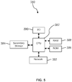
- FIG. 5 illustrates a computer system 380 suitable for implementing one or more aspects of an embodiment disclosed herein.
- the controller 110 described above with reference to FIG. 2A, FIG. 2B, and FIG. 2C may be implemented in a form substantially similar to the computer system 380.
- the NFC radio transceiver coupled to the bottom hole assembly 32 and the communication device at the surface of the wellbore 12 described above may be implemented in a form substantially similar to the computer system 380.
- the computer system 380 includes a processor 382 (which may be referred to as a central processor unit or CPU) that is in communication with memory devices including secondary storage 384, read only memory (ROM) 386, random access memory (RAM) 388, input/output (I/O) devices 390, and network connectivity devices 392.
- the processor 382 may be implemented as one or more CPU chips.
- a design that is still subject to frequent change may be preferred to be implemented in software, because re-spinning a hardware implementation is more expensive than re-spinning a software design.
- a design that is stable that will be produced in large volume may be preferred to be implemented in hardware, for example in an application specific integrated circuit (ASIC), because for large production runs the hardware implementation may be less expensive than the software implementation.
- ASIC application specific integrated circuit
- a design may be developed and tested in a software form and later transformed, by well known design rules, to an equivalent hardware implementation in an application specific integrated circuit that hardwires the instructions of the software.
- a machine controlled by a new ASIC is a particular machine or apparatus, likewise a computer that has been programmed and/or loaded with executable instructions may be viewed as a particular machine or apparatus.
- the secondary storage 384 is typically comprised of one or more disk drives or tape drives and is used for non-volatile storage of data and as an over-flow data storage device if RAM 388 is not large enough to hold all working data. Secondary storage 384 may be used to store programs which are loaded into RAM 388 when such programs are selected for execution.
- the ROM 386 is used to store instructions and perhaps data which are read during program execution. ROM 386 is a non-volatile memory device which typically has a small memory capacity relative to the larger memory capacity of secondary storage 384.
- the RAM 388 is used to store volatile data and perhaps to store instructions. Access to both ROM 386 and RAM 388 is typically faster than to secondary storage 384.
- the secondary storage 384, the RAM 388, and/or the ROM 386 may be referred to in some contexts as computer readable storage media and/or non-transitory computer readable media.
- I/O devices 390 may include printers, video monitors, liquid crystal displays (LCDs), touch screen displays, keyboards, keypads, switches, dials, mice, track balls, voice recognizers, card readers, paper tape readers, or other well-known input devices.
- LCDs liquid crystal displays
- touch screen displays keyboards, keypads, switches, dials, mice, track balls, voice recognizers, card readers, paper tape readers, or other well-known input devices.
- the network connectivity devices 392 may take the form of modems, modem banks, Ethernet cards, universal serial bus (USB) interface cards, serial interfaces, token ring cards, fiber distributed data interface (FDDI) cards, wireless local area network (WLAN) cards, radio transceiver cards such as code division multiple access (CDMA), global system for mobile communications (GSM), long-term evolution (LTE), worldwide interoperability for microwave access (WiMAX), and/or other air interface protocol radio transceiver cards, and other well-known network devices. These network connectivity devices 392 may enable the processor 382 to communicate with the Internet or one or more intranets.
- USB universal serial bus
- FDDI fiber distributed data interface
- WLAN wireless local area network
- radio transceiver cards such as code division multiple access (CDMA), global system for mobile communications (GSM), long-term evolution (LTE), worldwide interoperability for microwave access (WiMAX), and/or other air interface protocol radio transceiver cards, and other well-known network devices.
- CDMA code
- the processor 382 might receive information from the network, or might output information to the network in the course of performing the above-described method steps. Such information, which is often represented as a sequence of instructions to be executed using processor 382, may be received from and outputted to the network, for example, in the form of a computer data signal embodied in a carrier wave.
- Such information may be received from and outputted to the network, for example, in the form of a computer data baseband signal or signal embodied in a carrier wave.
- the baseband signal or signal embedded in the carrier wave may be generated according to several methods well known to one skilled in the art.
- the baseband signal and/or signal embedded in the carrier wave may be referred to in some contexts as a transitory signal.
- the processor 382 executes instructions, codes, computer programs, scripts which it accesses from hard disk, floppy disk, flash drives, optical disk (these various disk based systems may all be considered secondary storage 384), ROM 386, RAM 388, or the network connectivity devices 392. While only one processor 382 is shown, multiple processors may be present. Thus, while instructions may be discussed as executed by a processor, the instructions may be executed simultaneously, serially, or otherwise executed by one or multiple processors.
- the computer system 380 may comprise two or more computers in communication with each other that collaborate to perform a task.
- an application may be partitioned in such a way as to permit concurrent and/or parallel processing of the instructions of the application.
- the data processed by the application may be partitioned in such a way as to permit concurrent and/or parallel processing of different portions of a data set by the two or more computers.
- virtualization software may be employed by the computer system 380 to provide the functionality of a number of servers that is not directly bound to the number of computers in the computer system 380.
- virtualization software may provide twenty virtual servers on four physical computers.
- Cloud computing may comprise providing computing services via a network connection using dynamically scalable computing resources.
- Cloud computing may be supported, at least in part, by virtualization software.
- a cloud computing environment may be established by an enterprise and/or may be hired on an as-needed basis from a third party provider.
- Some cloud computing environments may comprise cloud computing resources owned and operated by the enterprise as well as cloud computing resources hired and/or leased from a third party provider.
- the computer program product may comprise one or more computer readable storage medium having computer usable program code embodied therein to implement the functionality disclosed above.
- the computer program product may comprise data structures, executable instructions, and other computer usable program code.
- the computer program product may be embodied in removable computer storage media and/or non-removable computer storage media.
- the removable computer readable storage medium may comprise, without limitation, a paper tape, a magnetic tape, magnetic disk, an optical disk, a solid state memory chip, for example analog magnetic tape, compact disk read only memory (CD-ROM) disks, floppy disks, jump drives, digital cards, multimedia cards, flash drives, and others.
- the computer program product may be suitable for loading, by the computer system 380, at least portions of the contents of the computer program product to the secondary storage 384, to the ROM 386, to the RAM 388, and/or to other non-volatile memory and volatile memory of the computer system 380.
- the processor 382 may process the executable instructions and/or data structures in part by directly accessing the computer program product, for example by reading from a CD-ROM disk inserted into a disk drive peripheral of the computer system 380.
- the processor 382 may process the executable instructions and/or data structures by remotely accessing the computer program product, for example by downloading the executable instructions and/or data structures from a remote server through the network connectivity devices 392.
- the computer program product may comprise instructions that promote the loading and/or copying of data, data structures, files, and/or executable instructions to the secondary storage 384, to the ROM 386, to the RAM 388, and/or to other non-volatile memory and volatile memory of the computer system 380.
- the secondary storage 384, the ROM 386, and the RAM 388 may be referred to as a non-transitory computer readable medium or a computer readable storage media.
- a dynamic RAM embodiment of the RAM 388 likewise, may be referred to as a non-transitory computer readable medium in that while the dynamic RAM receives electrical power and is operated in accordance with its design, for example during a period of time during which the computer 380 is turned on and operational, the dynamic RAM stores information that is written to it.
- the processor 382 may comprise an internal RAM, an internal ROM, a cache memory, and/or other internal non-transitory storage blocks, sections, or components that may be referred to in some contexts as non-transitory computer readable media or computer readable storage media.
Landscapes
- Engineering & Computer Science (AREA)
- Geology (AREA)
- Life Sciences & Earth Sciences (AREA)
- Mining & Mineral Resources (AREA)
- Physics & Mathematics (AREA)
- Geochemistry & Mineralogy (AREA)
- General Life Sciences & Earth Sciences (AREA)
- Environmental & Geological Engineering (AREA)
- Fluid Mechanics (AREA)
- Remote Sensing (AREA)
- Electromagnetism (AREA)
- Geophysics (AREA)
- Earth Drilling (AREA)
- Toys (AREA)
- Near-Field Transmission Systems (AREA)
- Selective Calling Equipment (AREA)
- General Factory Administration (AREA)
- Circuits Of Receivers In General (AREA)
- Details Of Television Systems (AREA)
Claims (18)
- Bloc de jonction en Y pour puits de forage, comprenant :un premier canal de forage (104) ;un second canal de forage (106) ;un déflecteur (108) capable d'être mis sélectivement à une position neutre, à une position sélectionnée vers un premier canal de forage, et à une position sélectionnée vers un second canal de forage ;un récepteur radio ;un contrôleur (110), dans lequel le contrôleur est configuré pour commander la position du déflecteur vers une position parmi la position neutre, la position sélectionnée vers le premier canal de forage, ou la position sélectionnée vers le second canal de forage, sur une entrée provenant du récepteur radio.
- Bloc de jonction en Y pour puits de forage selon la revendication 1, dans lequel le récepteur radio est un scanner pour étiquette d'identification à radiofréquences (RFID), et dans lequel l'entrée provenant du récepteur radio comprend une identité lue depuis une étiquette d'identité à radiofréquences.
- Bloc de jonction en Y pour puits de forage selon la revendication 1 ou 2, comprenant en outre un émetteur/récepteur radio de communication en champ rapproché (NFC), dans lequel le récepteur radio est un composant de l'émetteur/récepteur radio de communication en champ rapproché et, en option
comprenant encore en outre un capteur de position de déflecteur, dans lequel le contrôleur est en outre configuré pour commander l'émetteur/récepteur radio de communication en champ rapproché pour transmettre un message contenant une indication de la position du déflecteur sur la base d'une entrée provenant du capteur de position du déflecteur. - Bloc de jonction en Y pour puits de forage selon la revendication 1, 2 ou 3, dans lequel le déflecteur est en engagement sensiblement étanche avec le second canal de forage lorsqu'il est dans la position sélectionnée vers le premier canal de forage, et est engagement sensiblement étanche avec le premier canal de forage lorsqu'il est dans la position sélectionnée vers le second canal de forage.
- Bloc de jonction en Y pour puits de forage selon l'une quelconque des revendications précédentes, dans lequel le déflecteur maintient mécaniquement sa position après avoir été actionné à la position neutre, à la position sélectionnée vers le premier canal de forage et à la position sélectionnée vers le second canal de forage.
- Procédé pour exécuter un travail de service dans un puits de forage, comprenant les étapes consistant à :faire entrer un train d'outils (18) dans un puits de forage (12) au-dessus d'un premier bloc de jonction en Y (100), de sorte que le puits de forage comprend au moins un premier forage et un second forage, dans lequel le train d'outil porte au moins une étiquette d'identité à radiofréquences (RFID) sur une extrémité du train d'outil ;lire une première identité depuis ladite au moins une étiquette d'identité à radiofréquences par un premier contrôleur du premier bloc de jonction en Y; etdiriger le train d'outil vers le premier forage sur la base de la lecture de la première identité.
- Procédé selon la revendication 6, comprenant en outre les étapes consistant à :faire entrer le train d'outils dans le puits de forage au-dessus d'un second bloc de jonction en Y, dans lequelle puits de forage comprend en outre au moins un troisième forage ;lire une seconde identité depuis ladite au moins une étiquette d'identité à radiofréquences par un second contrôleur du second bloc de jonction en Y ; etdiriger le train d'outils vers le troisième forage sur la base de la lecture de la seconde identité.
- Procédé selon la revendication 6 ou 7, dans lequel le premier bloc de jonction en Y est positionné dans une jonction du premier forage et du second forage d'dans lequel le premier bloc de jonction en Y comprend un premier déflecteur (108) capable d'être sélectionné par le premier contrôleur (110) à une position neutre, à une position sélectionnée vers un premier canal de forage (104), et à une position sélectionnée vers un second canal de forage (106), et comprenant en outre les étapes consistant à :sélectionner le premier déflecteur à la position sélectionnée vers le premier canal de forage par le premier contrôleur sur la base de la lecture de la première identité ; etfaire entrer le train d'outils dans le premier forage.
- Procédé selon la revendication 8, comprenant en outre les étapes consistant à :faire entrer le train d'outils dans le premier canal de forage au-dessus d'un second bloc de jonction en Y, dans lequel le premier canal de forage comprend au moins le premier forage et un troisième forage ;lire une seconde identité depuis ladite au moins une étiquette d'identité à radiofréquences par un second contrôleur du second bloc de jonction en Y positionné dans une jonction du premier forage et du troisième forage, dans lequel le second bloc de jonction en Y comprend un second déflecteur capable d'être sélectionné par le second contrôleur à une position neutre, à une position sélectionnée vers le premier canal de forage, et à une position sélectionnée vers le troisième canal de forage ;sélectionner le second déflecteur à la position sélectionnée vers le troisième canal de forage par le second contrôleur sur la base de la lecture de la seconde identité ; etaprès que le second déflecteur a été sélectionné vers le troisième canal de forage, faire entrer le train d'outils dans le troisième forage et, en option :comprenant en outre les étapes consistant à :configurer le premier contrôleur pour sélectionner le premier déflecteur vers le troisième canal de forage sur la base de la lecture de la première identité ; etconfigurer le second contrôleur pour sélectionner le second déflecteur vers le troisième canal de forage sur la base de la lecture de la seconde identité.
- Procédé selon l'une quelconque des revendications 6 à 9, comprenant en outre les étapes consistant à :extraire le train d'outils hors du premier bloc de jonction en Y ;lire la première identité depuis ladite au moins une étiquette d'identité à radiofréquences par le premier contrôleur lorsque l'extrémité du train d'outils est extraite au-dessus du premier bloc de jonction en Y ; etsélectionner le premier déflecteur à la position neutre depuis la position sélectionnée vers le premier canal de forage par le premier contrôleur sur la base de la lecture de la première identité.
- Procédé selon l'une quelconque des revendications 6 à 10, dans lequel le premier contrôleur lit ladite au moins une étiquette d'identité à radiofréquences en recevant une entrée depuis un récepteur radio du premier bloc de jonction en Y, dans lequel le récepteur radio balaye ladite au moins une étiquette d'identité à radiofréquences.
- Procédé selon l'une quelconque des revendications 6 à 10, dans lequel le train d'outils comprend au moins un outil parmi un outil de fracturation et un outil de finition.
- Procédé pour exécuter un travail de service dans un puits de forage, comprenant les étapes consistant à :faire entrer un train d'outils (18) dans un puits de forage (12) au-dessus d'un premier bloc de jonction en Y (100), dans lequel le puits de forage comprend au moins un premier forage et un second forage,dans lequel le train d'outils porte un premier émetteur/récepteur de communication en champ rapproché (NFC) sur une extrémité du train d'outils ;transmettre un ordre depuis le premier émetteur/récepteur de communication en champ rapproché vers un second émetteur/récepteur de communication en champ rapproché couplé au premier bloc de jonction en Y ; etdiriger le train d'outils vers le premier forage sur la base de l'ordre.
- Procédé selon la revendication 13, dans lequel l'ordre et un ordre de position du déflecteur, dans lequel le premier bloc de jonction en Y comprend un contrôleur et un déflecteur capable d'être sélectionné par le contrôleur à une position neutre, à une position sélectionnée vers le premier canal de forage (104), et à une position sélectionnée vers le second canal de forage (106), et comprenant en outre les étapes consistant à:sélectionner le déflecteur à la position sélectionnée vers le premier canal de forage par le contrôleur sur la base de l'ordre de position du déflecteur ;transmettre un état de position du déflecteur depuis le second émetteur/récepteur de communication en champ rapproché vers le premier émetteur/récepteur de communication en champ rapproché.
- Procédé selon la revendication 14, comprenant en outre l'étape consistant à actionner le déflecteur à la position sélectionnée vers le premier canal de forage, l'actionnement étant motivé par une énergie électrique.
- Procédé selon la revendication 14, comprenant en outre l'étape consistant à actionner le déflecteur à la position sélectionnée vers le premier canal de forage, l'actionnement étant motivé par l'écoulement d'un fluide.
- Procédé selon l'une quelconque des revendications 13 à 16, dans lequel le train d'outils comprend un moyen comprenant un moyen parmi un tubage hélicoïdal, une ligne filaire, ou un tube à jointures.
- Procédé selon l'une quelconque des revendications 13 à 16, dans lequel le travail de service dans le puits de forage est au moins un travail parmi un travail de fracturation et un travail de finition du puits.
Priority Applications (1)
| Application Number | Priority Date | Filing Date | Title |
|---|---|---|---|
| EP17174506.0A EP3260652B1 (fr) | 2012-08-01 | 2012-08-01 | Déflecteur activé à distance |
Applications Claiming Priority (1)
| Application Number | Priority Date | Filing Date | Title |
|---|---|---|---|
| PCT/US2012/049227 WO2014021889A1 (fr) | 2012-08-01 | 2012-08-01 | Déflecteur activé à distance |
Related Child Applications (2)
| Application Number | Title | Priority Date | Filing Date |
|---|---|---|---|
| EP17174506.0A Division EP3260652B1 (fr) | 2012-08-01 | 2012-08-01 | Déflecteur activé à distance |
| EP17174506.0A Division-Into EP3260652B1 (fr) | 2012-08-01 | 2012-08-01 | Déflecteur activé à distance |
Publications (3)
| Publication Number | Publication Date |
|---|---|
| EP2880250A1 EP2880250A1 (fr) | 2015-06-10 |
| EP2880250A4 EP2880250A4 (fr) | 2016-08-24 |
| EP2880250B1 true EP2880250B1 (fr) | 2017-09-13 |
Family
ID=50028394
Family Applications (2)
| Application Number | Title | Priority Date | Filing Date |
|---|---|---|---|
| EP17174506.0A Not-in-force EP3260652B1 (fr) | 2012-08-01 | 2012-08-01 | Déflecteur activé à distance |
| EP12882531.2A Not-in-force EP2880250B1 (fr) | 2012-08-01 | 2012-08-01 | Déflecteur activé à distance |
Family Applications Before (1)
| Application Number | Title | Priority Date | Filing Date |
|---|---|---|---|
| EP17174506.0A Not-in-force EP3260652B1 (fr) | 2012-08-01 | 2012-08-01 | Déflecteur activé à distance |
Country Status (9)
| Country | Link |
|---|---|
| US (1) | US8789590B2 (fr) |
| EP (2) | EP3260652B1 (fr) |
| AU (2) | AU2012386508B2 (fr) |
| BR (1) | BR112015001943B1 (fr) |
| CA (1) | CA2880344C (fr) |
| EA (1) | EA029924B1 (fr) |
| MX (1) | MX359347B (fr) |
| SG (1) | SG11201500677TA (fr) |
| WO (1) | WO2014021889A1 (fr) |
Families Citing this family (11)
| Publication number | Priority date | Publication date | Assignee | Title |
|---|---|---|---|---|
| US9010422B2 (en) | 2012-08-01 | 2015-04-21 | Halliburton Energy Services, Inc. | Remote activated deflector |
| SG11201500677TA (en) | 2012-08-01 | 2015-02-27 | Halliburton Energy Services Inc | Remote activated deflector |
| BR112015008678B1 (pt) | 2012-10-16 | 2021-10-13 | Weatherford Technology Holdings, Llc | Método de controle do escoamento em um furo de um poço de petróleo ou gás e conjunto de controle de escoamento para uso em um poço de petróleo ou de gás |
| US10316646B2 (en) * | 2015-06-30 | 2019-06-11 | Halliburton Energy Services, Inc. | Position tracking for proppant conveying strings |
| US10435993B2 (en) | 2015-10-26 | 2019-10-08 | Halliburton Energy Services, Inc. | Junction isolation tool for fracking of wells with multiple laterals |
| RU2714398C2 (ru) * | 2015-11-17 | 2020-02-14 | Халлибертон Энерджи Сервисез, Инк. | Инструмент многоствольного бурения в течение одной спускоподъемной операции |
| AU2016433792B2 (en) | 2016-12-28 | 2022-03-03 | Halliburton Energy Services, Inc. | Actuatable deflector for a completion sleeve in multilateral wells |
| GB2580809B (en) | 2017-11-17 | 2022-03-02 | Halliburton Energy Services Inc | Actuator for multilateral wellbore system |
| AU2017440030B2 (en) | 2017-11-17 | 2023-06-22 | Halliburton Energy Services, Inc. | Actuator for multilateral wellbore system |
| AU2020219850B2 (en) * | 2019-02-08 | 2025-03-27 | Halliburton Energy Services, Inc. | Deflector assembly and efficient method for multi-stage fracturing a multilateral well using the same |
| WO2024220085A1 (fr) | 2023-04-21 | 2024-10-24 | Halliburton Energy Services, Inc. | Commande d'accès latéral dans des joints de fenêtre de fond de trou |
Family Cites Families (22)
| Publication number | Priority date | Publication date | Assignee | Title |
|---|---|---|---|---|
| US3472317A (en) * | 1965-11-03 | 1969-10-14 | Rockwell Mfg Co | Diverter |
| US3545474A (en) * | 1968-07-01 | 1970-12-08 | North American Rockwell | Tool diverter and system for directing tfl tools |
| US3599711A (en) * | 1969-07-07 | 1971-08-17 | Rockwell Mfg Co | Diverter |
| US3773062A (en) * | 1971-03-24 | 1973-11-20 | Keystone Intern Inc | Flow diverter valve |
| US3881516A (en) * | 1973-08-15 | 1975-05-06 | Exxon Production Research Co | Hydraulically operated diverter |
| GB2318817B (en) * | 1994-01-26 | 1998-06-24 | Baker Hughes Inc | Method for completing a wellbore |
| US5411082A (en) * | 1994-01-26 | 1995-05-02 | Baker Hughes Incorporated | Scoophead running tool |
| US6732801B2 (en) * | 1996-03-11 | 2004-05-11 | Schlumberger Technology Corporation | Apparatus and method for completing a junction of plural wellbores |
| US7014100B2 (en) | 2001-04-27 | 2006-03-21 | Marathon Oil Company | Process and assembly for identifying and tracking assets |
| US7252152B2 (en) * | 2003-06-18 | 2007-08-07 | Weatherford/Lamb, Inc. | Methods and apparatus for actuating a downhole tool |
| US7063148B2 (en) | 2003-12-01 | 2006-06-20 | Marathon Oil Company | Method and system for transmitting signals through a metal tubular |
| US20060042792A1 (en) * | 2004-08-24 | 2006-03-02 | Connell Michael L | Methods and apparatus for locating a lateral wellbore |
| US7373984B2 (en) * | 2004-12-22 | 2008-05-20 | Cdx Gas, Llc | Lining well bore junctions |
| US7459678B2 (en) * | 2006-05-12 | 2008-12-02 | Thermo Finnigan Llc | Switchable branched ion guide |
| US20080110643A1 (en) * | 2006-11-09 | 2008-05-15 | Baker Hughes Incorporated | Large bore packer and methods of setting same |
| US7757782B2 (en) * | 2006-12-07 | 2010-07-20 | Schlumberger Technology Corporation | Methods and apparatus for navigating a tool downhole |
| US20090090853A1 (en) | 2007-10-05 | 2009-04-09 | Schoen Alan E | Hybrid mass spectrometer with branched ion path and switch |
| US20090107725A1 (en) | 2007-10-30 | 2009-04-30 | Christy Thomas M | System and method for logging soil properties in a borehole |
| GB0804306D0 (en) | 2008-03-07 | 2008-04-16 | Petrowell Ltd | Device |
| US20090294124A1 (en) | 2008-05-28 | 2009-12-03 | Schlumberger Technology Corporation | System and method for shifting a tool in a well |
| SG11201500677TA (en) | 2012-08-01 | 2015-02-27 | Halliburton Energy Services Inc | Remote activated deflector |
| US9010422B2 (en) | 2012-08-01 | 2015-04-21 | Halliburton Energy Services, Inc. | Remote activated deflector |
-
2012
- 2012-08-01 SG SG11201500677TA patent/SG11201500677TA/en unknown
- 2012-08-01 AU AU2012386508A patent/AU2012386508B2/en not_active Ceased
- 2012-08-01 US US13/991,901 patent/US8789590B2/en active Active
- 2012-08-01 BR BR112015001943-9A patent/BR112015001943B1/pt active IP Right Grant
- 2012-08-01 EP EP17174506.0A patent/EP3260652B1/fr not_active Not-in-force
- 2012-08-01 EA EA201590121A patent/EA029924B1/ru not_active IP Right Cessation
- 2012-08-01 EP EP12882531.2A patent/EP2880250B1/fr not_active Not-in-force
- 2012-08-01 MX MX2015001315A patent/MX359347B/es active IP Right Grant
- 2012-08-01 WO PCT/US2012/049227 patent/WO2014021889A1/fr not_active Ceased
- 2012-08-01 CA CA2880344A patent/CA2880344C/fr active Active
-
2016
- 2016-01-07 AU AU2016200070A patent/AU2016200070B2/en not_active Ceased
Non-Patent Citations (1)
| Title |
|---|
| None * |
Also Published As
| Publication number | Publication date |
|---|---|
| MX359347B (es) | 2018-09-26 |
| CA2880344C (fr) | 2017-07-11 |
| WO2014021889A1 (fr) | 2014-02-06 |
| AU2016200070A1 (en) | 2016-02-04 |
| EA029924B1 (ru) | 2018-05-31 |
| EP2880250A4 (fr) | 2016-08-24 |
| EP2880250A1 (fr) | 2015-06-10 |
| EP3260652B1 (fr) | 2018-12-05 |
| EA201590121A1 (ru) | 2015-12-30 |
| EP3260652A1 (fr) | 2017-12-27 |
| CA2880344A1 (fr) | 2014-02-06 |
| BR112015001943A2 (pt) | 2017-07-04 |
| AU2016200070B2 (en) | 2016-08-11 |
| US20140124198A1 (en) | 2014-05-08 |
| US8789590B2 (en) | 2014-07-29 |
| BR112015001943B1 (pt) | 2020-12-22 |
| SG11201500677TA (en) | 2015-02-27 |
| AU2012386508B2 (en) | 2016-01-07 |
| MX2015001315A (es) | 2015-08-06 |
| AU2012386508A1 (en) | 2015-02-19 |
Similar Documents
| Publication | Publication Date | Title |
|---|---|---|
| EP2880250B1 (fr) | Déflecteur activé à distance | |
| US9010422B2 (en) | Remote activated deflector | |
| US9359841B2 (en) | Downhole robots and methods of using same | |
| US20130278432A1 (en) | Simultaneous Data Transmission of Multiple Nodes | |
| US20170167248A1 (en) | Lower Completion Communication System Integrity Check | |
| US9404358B2 (en) | Wiper plug for determining the orientation of a casing string in a wellbore | |
| CN106574497A (zh) | 钻机遥测系统 | |
| WO2015094204A1 (fr) | Placement d'outil de fond de trou activé par capteur | |
| US20210388691A1 (en) | Fluid communication method for hydraulic fracturing | |
| AU2012378310B2 (en) | Simultaneous data transmission of multiple nodes | |
| Pasimeni et al. | RFID technology expanded into the drilling space with particular emphasis on efficiencies | |
| Jongnarungsin et al. | Wireline Tractor Conveyance-A Technology Game Changer for the Gulf of Thailand | |
| Ghazali et al. | Effective Zonal Isolation Straddle Deployment in a Slim Deviated Well using Electric Line Tractor/Stroker Combination | |
| Chow et al. | High-Angle Gas Lift Valve Removal and Replacement in a Single Run | |
| Babin et al. | Pulling Subsea Wellhead Plugs Using a Slickline Downhole Electrical Power Generator Tool | |
| Syafruddin et al. | Thru-Tubing Isolation and Perforating in Large Casing Diameter | |
| Bargawi et al. | Case Histories: New Perforating Technology Enhances Workover Operations in Difficult Scenarios | |
| Stragiotti et al. | New Applications for 2 1/8" Well Tractor inside 5" Drill Pipe | |
| Ifediora et al. | A Novel Technology for Through Tubing Perforation in Highly Deviated Wells Where Electric Line Is Limited | |
| Soeprijadi et al. | Light Workovers in Handil and Bekapai Fields |
Legal Events
| Date | Code | Title | Description |
|---|---|---|---|
| PUAI | Public reference made under article 153(3) epc to a published international application that has entered the european phase |
Free format text: ORIGINAL CODE: 0009012 |
|
| 17P | Request for examination filed |
Effective date: 20150130 |
|
| AK | Designated contracting states |
Kind code of ref document: A1 Designated state(s): AL AT BE BG CH CY CZ DE DK EE ES FI FR GB GR HR HU IE IS IT LI LT LU LV MC MK MT NL NO PL PT RO RS SE SI SK SM TR |
|
| AX | Request for extension of the european patent |
Extension state: BA ME |
|
| DAX | Request for extension of the european patent (deleted) | ||
| RA4 | Supplementary search report drawn up and despatched (corrected) |
Effective date: 20160725 |
|
| RIC1 | Information provided on ipc code assigned before grant |
Ipc: E21B 23/12 20060101ALI20160719BHEP Ipc: E21B 7/06 20060101ALI20160719BHEP Ipc: E21B 34/16 20060101ALI20160719BHEP Ipc: E21B 21/10 20060101AFI20160719BHEP Ipc: E21B 41/00 20060101ALI20160719BHEP Ipc: E21B 47/12 20120101ALI20160719BHEP |
|
| GRAP | Despatch of communication of intention to grant a patent |
Free format text: ORIGINAL CODE: EPIDOSNIGR1 |
|
| RIC1 | Information provided on ipc code assigned before grant |
Ipc: E21B 7/06 20060101ALI20170310BHEP Ipc: E21B 21/10 20060101AFI20170310BHEP Ipc: E21B 41/00 20060101ALI20170310BHEP Ipc: E21B 34/16 20060101ALI20170310BHEP Ipc: E21B 23/12 20060101ALI20170310BHEP Ipc: E21B 47/12 20120101ALI20170310BHEP |
|
| INTG | Intention to grant announced |
Effective date: 20170327 |
|
| GRAS | Grant fee paid |
Free format text: ORIGINAL CODE: EPIDOSNIGR3 |
|
| GRAA | (expected) grant |
Free format text: ORIGINAL CODE: 0009210 |
|
| AK | Designated contracting states |
Kind code of ref document: B1 Designated state(s): AL AT BE BG CH CY CZ DE DK EE ES FI FR GB GR HR HU IE IS IT LI LT LU LV MC MK MT NL NO PL PT RO RS SE SI SK SM TR |
|
| REG | Reference to a national code |
Ref country code: GB Ref legal event code: FG4D |
|
| REG | Reference to a national code |
Ref country code: CH Ref legal event code: EP |
|
| REG | Reference to a national code |
Ref country code: IE Ref legal event code: FG4D |
|
| REG | Reference to a national code |
Ref country code: AT Ref legal event code: REF Ref document number: 928354 Country of ref document: AT Kind code of ref document: T Effective date: 20171015 |
|
| REG | Reference to a national code |
Ref country code: DE Ref legal event code: R096 Ref document number: 602012037461 Country of ref document: DE |
|
| REG | Reference to a national code |
Ref country code: NO Ref legal event code: T2 Effective date: 20170913 |
|
| REG | Reference to a national code |
Ref country code: NL Ref legal event code: MP Effective date: 20170913 |
|
| REG | Reference to a national code |
Ref country code: LT Ref legal event code: MG4D |
|
| PG25 | Lapsed in a contracting state [announced via postgrant information from national office to epo] |
Ref country code: LT Free format text: LAPSE BECAUSE OF FAILURE TO SUBMIT A TRANSLATION OF THE DESCRIPTION OR TO PAY THE FEE WITHIN THE PRESCRIBED TIME-LIMIT Effective date: 20170913 Ref country code: HR Free format text: LAPSE BECAUSE OF FAILURE TO SUBMIT A TRANSLATION OF THE DESCRIPTION OR TO PAY THE FEE WITHIN THE PRESCRIBED TIME-LIMIT Effective date: 20170913 Ref country code: SE Free format text: LAPSE BECAUSE OF FAILURE TO SUBMIT A TRANSLATION OF THE DESCRIPTION OR TO PAY THE FEE WITHIN THE PRESCRIBED TIME-LIMIT Effective date: 20170913 Ref country code: FI Free format text: LAPSE BECAUSE OF FAILURE TO SUBMIT A TRANSLATION OF THE DESCRIPTION OR TO PAY THE FEE WITHIN THE PRESCRIBED TIME-LIMIT Effective date: 20170913 |
|
| REG | Reference to a national code |
Ref country code: AT Ref legal event code: MK05 Ref document number: 928354 Country of ref document: AT Kind code of ref document: T Effective date: 20170913 |
|
| PG25 | Lapsed in a contracting state [announced via postgrant information from national office to epo] |
Ref country code: GR Free format text: LAPSE BECAUSE OF FAILURE TO SUBMIT A TRANSLATION OF THE DESCRIPTION OR TO PAY THE FEE WITHIN THE PRESCRIBED TIME-LIMIT Effective date: 20171214 Ref country code: LV Free format text: LAPSE BECAUSE OF FAILURE TO SUBMIT A TRANSLATION OF THE DESCRIPTION OR TO PAY THE FEE WITHIN THE PRESCRIBED TIME-LIMIT Effective date: 20170913 Ref country code: ES Free format text: LAPSE BECAUSE OF FAILURE TO SUBMIT A TRANSLATION OF THE DESCRIPTION OR TO PAY THE FEE WITHIN THE PRESCRIBED TIME-LIMIT Effective date: 20170913 Ref country code: BG Free format text: LAPSE BECAUSE OF FAILURE TO SUBMIT A TRANSLATION OF THE DESCRIPTION OR TO PAY THE FEE WITHIN THE PRESCRIBED TIME-LIMIT Effective date: 20171213 Ref country code: RS Free format text: LAPSE BECAUSE OF FAILURE TO SUBMIT A TRANSLATION OF THE DESCRIPTION OR TO PAY THE FEE WITHIN THE PRESCRIBED TIME-LIMIT Effective date: 20170913 |
|
| PG25 | Lapsed in a contracting state [announced via postgrant information from national office to epo] |
Ref country code: NL Free format text: LAPSE BECAUSE OF FAILURE TO SUBMIT A TRANSLATION OF THE DESCRIPTION OR TO PAY THE FEE WITHIN THE PRESCRIBED TIME-LIMIT Effective date: 20170913 |
|
| PG25 | Lapsed in a contracting state [announced via postgrant information from national office to epo] |
Ref country code: CZ Free format text: LAPSE BECAUSE OF FAILURE TO SUBMIT A TRANSLATION OF THE DESCRIPTION OR TO PAY THE FEE WITHIN THE PRESCRIBED TIME-LIMIT Effective date: 20170913 Ref country code: PL Free format text: LAPSE BECAUSE OF FAILURE TO SUBMIT A TRANSLATION OF THE DESCRIPTION OR TO PAY THE FEE WITHIN THE PRESCRIBED TIME-LIMIT Effective date: 20170913 Ref country code: RO Free format text: LAPSE BECAUSE OF FAILURE TO SUBMIT A TRANSLATION OF THE DESCRIPTION OR TO PAY THE FEE WITHIN THE PRESCRIBED TIME-LIMIT Effective date: 20170913 |
|
| PG25 | Lapsed in a contracting state [announced via postgrant information from national office to epo] |
Ref country code: IS Free format text: LAPSE BECAUSE OF FAILURE TO SUBMIT A TRANSLATION OF THE DESCRIPTION OR TO PAY THE FEE WITHIN THE PRESCRIBED TIME-LIMIT Effective date: 20180113 Ref country code: SM Free format text: LAPSE BECAUSE OF FAILURE TO SUBMIT A TRANSLATION OF THE DESCRIPTION OR TO PAY THE FEE WITHIN THE PRESCRIBED TIME-LIMIT Effective date: 20170913 Ref country code: IT Free format text: LAPSE BECAUSE OF FAILURE TO SUBMIT A TRANSLATION OF THE DESCRIPTION OR TO PAY THE FEE WITHIN THE PRESCRIBED TIME-LIMIT Effective date: 20170913 Ref country code: SK Free format text: LAPSE BECAUSE OF FAILURE TO SUBMIT A TRANSLATION OF THE DESCRIPTION OR TO PAY THE FEE WITHIN THE PRESCRIBED TIME-LIMIT Effective date: 20170913 Ref country code: AT Free format text: LAPSE BECAUSE OF FAILURE TO SUBMIT A TRANSLATION OF THE DESCRIPTION OR TO PAY THE FEE WITHIN THE PRESCRIBED TIME-LIMIT Effective date: 20170913 Ref country code: EE Free format text: LAPSE BECAUSE OF FAILURE TO SUBMIT A TRANSLATION OF THE DESCRIPTION OR TO PAY THE FEE WITHIN THE PRESCRIBED TIME-LIMIT Effective date: 20170913 |
|
| REG | Reference to a national code |
Ref country code: DE Ref legal event code: R097 Ref document number: 602012037461 Country of ref document: DE |
|
| PLBE | No opposition filed within time limit |
Free format text: ORIGINAL CODE: 0009261 |
|
| STAA | Information on the status of an ep patent application or granted ep patent |
Free format text: STATUS: NO OPPOSITION FILED WITHIN TIME LIMIT |
|
| PG25 | Lapsed in a contracting state [announced via postgrant information from national office to epo] |
Ref country code: DK Free format text: LAPSE BECAUSE OF FAILURE TO SUBMIT A TRANSLATION OF THE DESCRIPTION OR TO PAY THE FEE WITHIN THE PRESCRIBED TIME-LIMIT Effective date: 20170913 |
|
| 26N | No opposition filed |
Effective date: 20180614 |
|
| PG25 | Lapsed in a contracting state [announced via postgrant information from national office to epo] |
Ref country code: SI Free format text: LAPSE BECAUSE OF FAILURE TO SUBMIT A TRANSLATION OF THE DESCRIPTION OR TO PAY THE FEE WITHIN THE PRESCRIBED TIME-LIMIT Effective date: 20170913 |
|
| REG | Reference to a national code |
Ref country code: DE Ref legal event code: R119 Ref document number: 602012037461 Country of ref document: DE |
|
| PG25 | Lapsed in a contracting state [announced via postgrant information from national office to epo] |
Ref country code: MC Free format text: LAPSE BECAUSE OF FAILURE TO SUBMIT A TRANSLATION OF THE DESCRIPTION OR TO PAY THE FEE WITHIN THE PRESCRIBED TIME-LIMIT Effective date: 20170913 |
|
| REG | Reference to a national code |
Ref country code: CH Ref legal event code: PL |
|
| GBPC | Gb: european patent ceased through non-payment of renewal fee |
Effective date: 20180801 |
|
| PG25 | Lapsed in a contracting state [announced via postgrant information from national office to epo] |
Ref country code: LI Free format text: LAPSE BECAUSE OF NON-PAYMENT OF DUE FEES Effective date: 20180831 Ref country code: LU Free format text: LAPSE BECAUSE OF NON-PAYMENT OF DUE FEES Effective date: 20180801 Ref country code: CH Free format text: LAPSE BECAUSE OF NON-PAYMENT OF DUE FEES Effective date: 20180831 |
|
| REG | Reference to a national code |
Ref country code: BE Ref legal event code: MM Effective date: 20180831 |
|
| REG | Reference to a national code |
Ref country code: IE Ref legal event code: MM4A |
|
| PG25 | Lapsed in a contracting state [announced via postgrant information from national office to epo] |
Ref country code: DE Free format text: LAPSE BECAUSE OF NON-PAYMENT OF DUE FEES Effective date: 20190301 Ref country code: IE Free format text: LAPSE BECAUSE OF NON-PAYMENT OF DUE FEES Effective date: 20180801 |
|
| PG25 | Lapsed in a contracting state [announced via postgrant information from national office to epo] |
Ref country code: BE Free format text: LAPSE BECAUSE OF NON-PAYMENT OF DUE FEES Effective date: 20180831 Ref country code: FR Free format text: LAPSE BECAUSE OF NON-PAYMENT OF DUE FEES Effective date: 20180831 |
|
| PG25 | Lapsed in a contracting state [announced via postgrant information from national office to epo] |
Ref country code: GB Free format text: LAPSE BECAUSE OF NON-PAYMENT OF DUE FEES Effective date: 20180801 |
|
| PG25 | Lapsed in a contracting state [announced via postgrant information from national office to epo] |
Ref country code: MT Free format text: LAPSE BECAUSE OF NON-PAYMENT OF DUE FEES Effective date: 20180801 |
|
| PG25 | Lapsed in a contracting state [announced via postgrant information from national office to epo] |
Ref country code: TR Free format text: LAPSE BECAUSE OF FAILURE TO SUBMIT A TRANSLATION OF THE DESCRIPTION OR TO PAY THE FEE WITHIN THE PRESCRIBED TIME-LIMIT Effective date: 20170913 |
|
| PG25 | Lapsed in a contracting state [announced via postgrant information from national office to epo] |
Ref country code: HU Free format text: LAPSE BECAUSE OF FAILURE TO SUBMIT A TRANSLATION OF THE DESCRIPTION OR TO PAY THE FEE WITHIN THE PRESCRIBED TIME-LIMIT; INVALID AB INITIO Effective date: 20120801 Ref country code: PT Free format text: LAPSE BECAUSE OF FAILURE TO SUBMIT A TRANSLATION OF THE DESCRIPTION OR TO PAY THE FEE WITHIN THE PRESCRIBED TIME-LIMIT Effective date: 20170913 |
|
| PG25 | Lapsed in a contracting state [announced via postgrant information from national office to epo] |
Ref country code: MK Free format text: LAPSE BECAUSE OF NON-PAYMENT OF DUE FEES Effective date: 20170913 Ref country code: CY Free format text: LAPSE BECAUSE OF FAILURE TO SUBMIT A TRANSLATION OF THE DESCRIPTION OR TO PAY THE FEE WITHIN THE PRESCRIBED TIME-LIMIT Effective date: 20170913 |
|
| PG25 | Lapsed in a contracting state [announced via postgrant information from national office to epo] |
Ref country code: AL Free format text: LAPSE BECAUSE OF FAILURE TO SUBMIT A TRANSLATION OF THE DESCRIPTION OR TO PAY THE FEE WITHIN THE PRESCRIBED TIME-LIMIT Effective date: 20170913 |
|
| PGFP | Annual fee paid to national office [announced via postgrant information from national office to epo] |
Ref country code: NO Payment date: 20240725 Year of fee payment: 13 |
|
| PG25 | Lapsed in a contracting state [announced via postgrant information from national office to epo] |
Ref country code: NO Free format text: LAPSE BECAUSE OF NON-PAYMENT OF DUE FEES Effective date: 20250831 |