EP2884036A1 - Étanchéité comprenant au moins un angle de fixation et au moins une butée pour le montage sur l'arête d'une rainure dans un vantail ou autre - Google Patents
Étanchéité comprenant au moins un angle de fixation et au moins une butée pour le montage sur l'arête d'une rainure dans un vantail ou autre Download PDFInfo
- Publication number
- EP2884036A1 EP2884036A1 EP14195217.6A EP14195217A EP2884036A1 EP 2884036 A1 EP2884036 A1 EP 2884036A1 EP 14195217 A EP14195217 A EP 14195217A EP 2884036 A1 EP2884036 A1 EP 2884036A1
- Authority
- EP
- European Patent Office
- Prior art keywords
- seal
- leg
- housing
- stop
- seal according
- Prior art date
- Legal status (The legal status is an assumption and is not a legal conclusion. Google has not performed a legal analysis and makes no representation as to the accuracy of the status listed.)
- Granted
Links
Images


Classifications
-
- E—FIXED CONSTRUCTIONS
- E06—DOORS, WINDOWS, SHUTTERS, OR ROLLER BLINDS IN GENERAL; LADDERS
- E06B—FIXED OR MOVABLE CLOSURES FOR OPENINGS IN BUILDINGS, VEHICLES, FENCES OR LIKE ENCLOSURES IN GENERAL, e.g. DOORS, WINDOWS, BLINDS, GATES
- E06B7/00—Special arrangements or measures in connection with doors or windows
- E06B7/16—Sealing arrangements on wings or parts co-operating with the wings
- E06B7/18—Sealing arrangements on wings or parts co-operating with the wings by means of movable edgings, e.g. draught sealings additionally used for bolting, e.g. by spring force or with operating lever
- E06B7/20—Sealing arrangements on wings or parts co-operating with the wings by means of movable edgings, e.g. draught sealings additionally used for bolting, e.g. by spring force or with operating lever automatically withdrawn when the wing is opened, e.g. by means of magnetic attraction, a pin or an inclined surface, especially for sills
- E06B7/215—Sealing arrangements on wings or parts co-operating with the wings by means of movable edgings, e.g. draught sealings additionally used for bolting, e.g. by spring force or with operating lever automatically withdrawn when the wing is opened, e.g. by means of magnetic attraction, a pin or an inclined surface, especially for sills with sealing strip being moved to a retracted position by elastic means, e.g. springs
Definitions
- the present invention relates to a seal comprising at least one mounting bracket for fixing the seal of the edge of a groove such that a housing of the seal does not protrude beyond the edge of the groove.
- a seal is known whose housing has a hat profile.
- This hat profile allows accurate positioning of the seal housing in the groove, as the outwardly flared legs (similar to the brim of a hat) of the hat profile form stops which bear against the underside of the door panel in which the groove is provided. Although the seal protrudes with the outwardly flared legs over the edge of the groove.
- the seal also has a favorable position for sound insulation.
- the seal has at least one stop by which the seal is positioned so that in a mounted on a door leaf condition of the seal, the housing of the seal does not or only slightly protrudes beyond an edge of the groove.
- “Slightly protruding” in this sense means, for example, that the housing can protrude beyond the edge of the groove by the thickness of a wall of the housing.
- the at least one mounting bracket is connected to a lock-side or belt-side end of the housing with this.
- the hinge side of the seal is the side of the seal that lies after the assembly of the seal on the hinge side of the seal.
- the mounting bracket may include a first leg suitable and adapted for attachment to the door panel. At least one structure may be provided in or on this leg, which serves to fasten the first leg to the door leaf. Such a structure may be, for example, a hole in the leg.
- the mounting bracket may have a second leg that can be connected to the housing.
- the connection between the second leg can be made for example by positive engagement and / or by frictional connection.
- the at least one stop may be arranged in a plane parallel to a plane in which the second leg of the mounting bracket is located. It could be arranged in a plane parallel to a plane in which a ridge of the U-shaped or H-shaped housing is located.
- the stop may have a round or angled, in particular a rectangular cross-section.
- the at least one stop is preferably provided at a distance from the second leg.
- the distance of the second leg from the at least one stop may correspond to the distance between a connection point of the second leg of the mounting bracket with the housing of the seal and a free end of a leg of the substantially U-shaped or H-shaped housing.
- the free end may be in a mounting of the seal at the lower end of a door, in particular the bottom end of the leg.
- the free end of the leg may be a ceiling end of the leg of the housing.
- a seal according to the invention can be designed such that the second leg and the at least one stop in a projection in the plane in which the second leg is located next to each other.
- the at least one stop or one of the stops is provided on the at least one mounting bracket.
- the at least one stop and the second leg can be connected to each other via a web of the mounting bracket.
- this web lies in the same plane as the first leg or in a plane parallel to the plane in which the first leg lies.
- abutment and an end of a leg of the substantially U-shaped or H-shaped housing abut each other.
- the mounting bracket may include two stops that may lie on either side of the second leg in a projection in the plane in which the second leg is located.
- the two stops can form a fork-like structure.
- the two stops may have a distance from one another which corresponds to the width of the housing or is slightly larger or smaller than this width.
- the at least one stop or one of the stops is provided on the housing.
- the housing may have a hat profile.
- At least one stop is connected to one end of a leg of the otherwise preferably substantially U-shaped or H-shaped housing.
- This Stop can be angled at approximately 90 ° with respect to the leg of the housing.
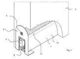
- the seals shown in the figures are very similar. It will be initially based on the first, in the FIGS. 1 to 5 illustrated seal the similarities of the first and the second seal described in more detail. Then the specific characteristics of the first seal will be described. Subsequently, the differences of the second, in the FIGS. 6 to 9 illustrated seal to the first seal. Because of the great similarity of the first and the second seal the same or similar components of the two seals are denoted by the same reference numerals.
- the first gasket 1 is mounted in a groove at the lower end of a door panel and serves to seal an air gap between the door panel and a floor in a closed state of a door.
- the first seal 1 is a so-called automatic door seal.
- the first seal has a housing 1 which has a substantially U-shaped cross-section. It therefore has a web 11 and two legs 10. On the inside of the legs are provided with only a small distance from the web 11, parallel to the web 1 extending collar 13.
- the housing 1 of the seal is attached to the door leaf.
- two mounting brackets 2 are provided.
- the mounting brackets 2 have two legs 21, 22 which are at an angle of approximately 90 ° to each other.
- a first of the two legs 21, 22 of each of the two Mounting bracket 2, namely the leg 21, each has a hole 23. Through these holes 23 is ever a screw 3 out with which the mounting bracket 2 are fixed to narrow sides of the door panel T.
- the second legs 22 are inserted at the band side or the lock side into the housing 1, specifically between the web 11 and the collar 13. The second leg thus serves for a positive fastening of the housing at the second legs 22.
- a mechanism which is connected to the housing 1 and of which only a trigger 4 is shown.
- the mechanism carries a retaining profile 6.
- the holding profile and the sealing profile together are referred to as a sealing strip.
- the housing 1 of the first seal is mounted in the groove of the door panel T so that the housing 1 is completely received in the groove and the free ends of the legs 22 flush with an edge of the groove and thereby with an underside of the door panel T.
- This is ensured by the fact that the seal stops 24, the Part of the mounting bracket 2 are.
- Two stops 24 are provided on a mounting bracket 2.
- the stops 24 lie in a plane parallel to the second leg 22 and each stop 24 is connected via a web 23 with the first leg 21 and the second leg 22 of a mounting bracket.
- the web 23 lies in the plane of the first leg.
- the webs 23 of a mounting bracket are parallel to each other and have a distance from one another which corresponds approximately to the width of the housing 1. The same distance from each other have the stops 24, which are also parallel to each other.
- the plane in which the second leg 22 is located, and the plane in which the stops 24 are located, have a distance from one another which is approximately equal to the distance between the surface of the collar 13 lying on the side of the web 11 of the housing 1 of the seal. at which the second leg 22 of the mounting bracket 2 abut, corresponds to the free ends of the legs 10 of the housing 1.
- the housing 1 of the second seal projects slightly beyond the groove in the door leaf T, specifically around the material or wall thickness of stops 12 which are connected to the ends of the legs 10 of the housing 1 facing away from the web 11.
- the housing has a hat profile in cross section, wherein the brim of the imitated by the profile hat forms the stops 12. These stops 12 are at mounted second seal on the underside of the door leaf T.
- the attachment angle 2 of the second seal can be shaped in a known manner and - in particular in Fig. 9 shown - have a first leg 21 with a hole 25 for a screw 3 and a second leg 22.
- the first leg 21 and the second leg 22 have the same function as in the first seal.
- the in the FIG. 10 The arrangement shown differs from the arrangement according to the FIGS. 1 to 4 only by the mounting bracket 2 and the resulting position of the housing 1 relative to the edge K of the groove in the door leaf.
- the mounting bracket 2 of the arrangement according to the FIGS. 1 to 4 the Indian FIG. 5 shown alone, the web 23 is longer than in the mounting bracket 2 of the arrangement according to Fig. 10 , As a result, the housing is flush with the edge K of the groove.
- the web 23 of the mounting bracket 2 of the arrangement according to the FIG. 10 is shorter than the web 23 of the mounting bracket 2 of the arrangement according to the thickness of the stops 24 FIGS. 1 to 4 , As a result, the housing projects slightly beyond the edge K of the groove and closes flush with the stops 24.
Landscapes
- Engineering & Computer Science (AREA)
- Civil Engineering (AREA)
- Structural Engineering (AREA)
- Specific Sealing Or Ventilating Devices For Doors And Windows (AREA)
Applications Claiming Priority (1)
| Application Number | Priority Date | Filing Date | Title |
|---|---|---|---|
| DE201320105687 DE202013105687U1 (de) | 2013-12-13 | 2013-12-13 | Dichtung umfassend wenigstens einen Befestigungswinkel und wenigstens einen Anschlag zur Montage an der Kante einer Nut in einem Türblatt o.ä. |
Publications (2)
| Publication Number | Publication Date |
|---|---|
| EP2884036A1 true EP2884036A1 (fr) | 2015-06-17 |
| EP2884036B1 EP2884036B1 (fr) | 2019-08-28 |
Family
ID=52023186
Family Applications (1)
| Application Number | Title | Priority Date | Filing Date |
|---|---|---|---|
| EP14195217.6A Active EP2884036B1 (fr) | 2013-12-13 | 2014-11-27 | Étanchéité comprenant au moins un angle de fixation et au moins une butée pour le montage sur l'arête d'une rainure dans un vantail ou autre |
Country Status (4)
| Country | Link |
|---|---|
| EP (1) | EP2884036B1 (fr) |
| CN (1) | CN104863478B (fr) |
| DE (1) | DE202013105687U1 (fr) |
| DK (1) | DK2884036T3 (fr) |
Families Citing this family (3)
| Publication number | Priority date | Publication date | Assignee | Title |
|---|---|---|---|---|
| DE202014101295U1 (de) | 2014-03-20 | 2015-07-01 | Athmer Ohg | Dichtung für Türen zum Abdichten eines Luftspaltes zwischen einem Türflügel einerseits und einem Türahmen, einem Fußboden, einer Zimmerdecke, einem Sturz o.ä. andererseits |
| CN105156000B (zh) * | 2015-09-30 | 2017-03-22 | 江苏肯帝亚森工科技股份有限公司 | 防尘隔音装置及其防尘隔音门 |
| DE102015118174A1 (de) | 2015-10-23 | 2017-04-27 | Huga Hubert Gaisendrees KG | Dichtungsvorrichtung für eine Schiebetür sowie damit versehene Schiebetür |
Citations (3)
| Publication number | Priority date | Publication date | Assignee | Title |
|---|---|---|---|---|
| EP0338974A2 (fr) | 1988-04-19 | 1989-10-25 | " Planet" Matthias Jaggi | Dispositif d'étanchéité pour portes sans seuil |
| EP1439278A2 (fr) | 2003-01-08 | 2004-07-21 | Firma F. Athmer | Joint, notamment joint de contact ou joint automatiquement abaissable pour portes avec support adjustable |
| EP1122394B1 (fr) | 2000-02-07 | 2005-12-07 | Planet GDZ AG | Battant de porte pour une porte sans seuil |
Family Cites Families (13)
| Publication number | Priority date | Publication date | Assignee | Title |
|---|---|---|---|---|
| US1422569A (en) * | 1921-05-23 | 1922-07-11 | John W Hammes | Floating weather strip |
| DE804248C (de) * | 1949-12-01 | 1951-04-19 | Otto Kachel | Abdichtungsvorrichtung an Tueren |
| DE1791375U (de) * | 1959-03-28 | 1959-07-02 | Leo Beck | Tuerenunterkantendichtung fuer schwellenlose tueren. |
| FR1585622A (fr) * | 1968-06-17 | 1970-01-30 | ||
| DE1996239U (de) * | 1968-08-22 | 1968-11-07 | Joachim Gittel | Wassarabweisprofil fuer holzfenster aller art |
| CH709210B1 (de) * | 2001-02-15 | 2015-08-14 | Planet Gdz Ag | Vorrichtung zum Abdichten der unteren Stirnfläche einer schwellenlosen Türe. |
| DE20219174U1 (de) * | 2002-12-11 | 2003-03-06 | Fa. F. Athmer, 59757 Arnsberg | Dichtung insbesondere selbsttätig absenkende Bodendichtung für Türen |
| CN2625544Y (zh) * | 2003-06-18 | 2004-07-14 | 马龙建筑及机械(天津)有限公司 | 内装升降式门底自动密封条 |
| DE202004007565U1 (de) * | 2004-05-07 | 2005-09-22 | Sylid Systemlogistik Und Industriedienstleistung Gmbh | Bodendichtung mit Federband |
| DE202005011984U1 (de) * | 2005-07-30 | 2005-10-13 | Fa. F. Athmer | Dichtungsanordnung für eine Schiebetür |
| DE102005047854A1 (de) * | 2005-10-05 | 2007-04-12 | Fa. F. Athmer | Dichtungen, Verfahren und Vorrichtung zum Montieren der Dichtungen und Türen mit den Dichtungen |
| CN2866770Y (zh) * | 2006-01-26 | 2007-02-07 | 张建萍 | 升降式门底自动防火密封条 |
| CN202937150U (zh) * | 2012-10-15 | 2013-05-15 | 天津市佐佳奇装饰材料制造有限公司 | 一种自动门底密封装置 |
-
2013
- 2013-12-13 DE DE201320105687 patent/DE202013105687U1/de not_active Expired - Lifetime
-
2014
- 2014-11-27 EP EP14195217.6A patent/EP2884036B1/fr active Active
- 2014-11-27 DK DK14195217T patent/DK2884036T3/da active
- 2014-12-11 CN CN201410752364.5A patent/CN104863478B/zh active Active
Patent Citations (3)
| Publication number | Priority date | Publication date | Assignee | Title |
|---|---|---|---|---|
| EP0338974A2 (fr) | 1988-04-19 | 1989-10-25 | " Planet" Matthias Jaggi | Dispositif d'étanchéité pour portes sans seuil |
| EP1122394B1 (fr) | 2000-02-07 | 2005-12-07 | Planet GDZ AG | Battant de porte pour une porte sans seuil |
| EP1439278A2 (fr) | 2003-01-08 | 2004-07-21 | Firma F. Athmer | Joint, notamment joint de contact ou joint automatiquement abaissable pour portes avec support adjustable |
Also Published As
| Publication number | Publication date |
|---|---|
| CN104863478A (zh) | 2015-08-26 |
| EP2884036B1 (fr) | 2019-08-28 |
| CN104863478B (zh) | 2019-03-22 |
| DE202013105687U1 (de) | 2015-03-16 |
| DK2884036T3 (da) | 2019-11-11 |
Similar Documents
| Publication | Publication Date | Title |
|---|---|---|
| DE102016123230B3 (de) | Scharnieranordnung für ein Schaltschrankgehäuse und ein entsprechendes Schaltschrankgehäuse | |
| AT18487U1 (de) | Verbesserte Inpektionsklapptür | |
| EP2884036B1 (fr) | Étanchéité comprenant au moins un angle de fixation et au moins une butée pour le montage sur l'arête d'une rainure dans un vantail ou autre | |
| EP1335099A2 (fr) | Dispositif d'étanchéité pour une porte ou une fenêtre | |
| EP1439278A2 (fr) | Joint, notamment joint de contact ou joint automatiquement abaissable pour portes avec support adjustable | |
| DE102010049782A1 (de) | Rahmensystem für ein Schutzgitter | |
| WO2015074933A1 (fr) | Dispositif de retenue pour boîtier et procédé de montage du boîtier à l'aide du dispositif de retenue | |
| DE102007008667B4 (de) | Befestigungsvorrichtung für ein Aufsatzelement | |
| DE3606812A1 (de) | Verkleidung fuer einen einstiegsschweller eines kraftfahrzeugs | |
| EP0620351A1 (fr) | Ferme porte | |
| EP1898041B1 (fr) | Procedé et dispositif de montage d'accessoires sur cadres de bâtiments | |
| WO2019149301A1 (fr) | Système de positionnement d'une pièce plate au niveau d'un châssis d'armoire électrique et procédé correspondant | |
| EP2708693A1 (fr) | Cadre de battant ouvrant-coulissant | |
| EP2946955B1 (fr) | Système comprenant une pièce composite et un élément de cadre d'une fenêtre de porte de véhicule | |
| DE202022105475U1 (de) | Bodenanordnung, längliches Bodenprofil und Abschlussprofil | |
| DE10339333B4 (de) | Bodentürschließer | |
| DE102016218262B4 (de) | Dachfenster | |
| DE202014103071U1 (de) | Rollladenkasten | |
| EP1072751A2 (fr) | Porte avec un joint d'étanchéité de sol | |
| EP2787160B1 (fr) | Joint de verrou et système de joint doté de celui-ci | |
| EP2754817A2 (fr) | Plaque de fixation | |
| DE202019103487U1 (de) | Spreizbarer Eckwinkel | |
| DE10354310A1 (de) | Dichtung insbesondere selbsttätig absenkende Bodendichtung für Türen | |
| EP2256279B1 (fr) | Pièce terminale pour la fermeture latérale d'une barre de recouvrement | |
| DE102011120118B4 (de) | Beschlag |
Legal Events
| Date | Code | Title | Description |
|---|---|---|---|
| PUAI | Public reference made under article 153(3) epc to a published international application that has entered the european phase |
Free format text: ORIGINAL CODE: 0009012 |
|
| 17P | Request for examination filed |
Effective date: 20141127 |
|
| AK | Designated contracting states |
Kind code of ref document: A1 Designated state(s): AL AT BE BG CH CY CZ DE DK EE ES FI FR GB GR HR HU IE IS IT LI LT LU LV MC MK MT NL NO PL PT RO RS SE SI SK SM TR |
|
| AX | Request for extension of the european patent |
Extension state: BA ME |
|
| R17P | Request for examination filed (corrected) |
Effective date: 20151103 |
|
| RBV | Designated contracting states (corrected) |
Designated state(s): AL AT BE BG CH CY CZ DE DK EE ES FI FR GB GR HR HU IE IS IT LI LT LU LV MC MK MT NL NO PL PT RO RS SE SI SK SM TR |
|
| STAA | Information on the status of an ep patent application or granted ep patent |
Free format text: STATUS: EXAMINATION IS IN PROGRESS |
|
| 17Q | First examination report despatched |
Effective date: 20170627 |
|
| GRAP | Despatch of communication of intention to grant a patent |
Free format text: ORIGINAL CODE: EPIDOSNIGR1 |
|
| STAA | Information on the status of an ep patent application or granted ep patent |
Free format text: STATUS: GRANT OF PATENT IS INTENDED |
|
| INTG | Intention to grant announced |
Effective date: 20190325 |
|
| GRAS | Grant fee paid |
Free format text: ORIGINAL CODE: EPIDOSNIGR3 |
|
| GRAA | (expected) grant |
Free format text: ORIGINAL CODE: 0009210 |
|
| STAA | Information on the status of an ep patent application or granted ep patent |
Free format text: STATUS: THE PATENT HAS BEEN GRANTED |
|
| AK | Designated contracting states |
Kind code of ref document: B1 Designated state(s): AL AT BE BG CH CY CZ DE DK EE ES FI FR GB GR HR HU IE IS IT LI LT LU LV MC MK MT NL NO PL PT RO RS SE SI SK SM TR |
|
| REG | Reference to a national code |
Ref country code: GB Ref legal event code: FG4D Free format text: NOT ENGLISH |
|
| REG | Reference to a national code |
Ref country code: CH Ref legal event code: EP |
|
| REG | Reference to a national code |
Ref country code: AT Ref legal event code: REF Ref document number: 1172618 Country of ref document: AT Kind code of ref document: T Effective date: 20190915 |
|
| REG | Reference to a national code |
Ref country code: IE Ref legal event code: FG4D Free format text: LANGUAGE OF EP DOCUMENT: GERMAN |
|
| REG | Reference to a national code |
Ref country code: DE Ref legal event code: R096 Ref document number: 502014012503 Country of ref document: DE |
|
| REG | Reference to a national code |
Ref country code: DK Ref legal event code: T3 Effective date: 20191108 |
|
| REG | Reference to a national code |
Ref country code: NL Ref legal event code: FP |
|
| REG | Reference to a national code |
Ref country code: SE Ref legal event code: TRGR |
|
| REG | Reference to a national code |
Ref country code: NO Ref legal event code: T2 Effective date: 20190828 |
|
| REG | Reference to a national code |
Ref country code: LT Ref legal event code: MG4D |
|
| PG25 | Lapsed in a contracting state [announced via postgrant information from national office to epo] |
Ref country code: FI Free format text: LAPSE BECAUSE OF FAILURE TO SUBMIT A TRANSLATION OF THE DESCRIPTION OR TO PAY THE FEE WITHIN THE PRESCRIBED TIME-LIMIT Effective date: 20190828 Ref country code: PT Free format text: LAPSE BECAUSE OF FAILURE TO SUBMIT A TRANSLATION OF THE DESCRIPTION OR TO PAY THE FEE WITHIN THE PRESCRIBED TIME-LIMIT Effective date: 20191230 Ref country code: LT Free format text: LAPSE BECAUSE OF FAILURE TO SUBMIT A TRANSLATION OF THE DESCRIPTION OR TO PAY THE FEE WITHIN THE PRESCRIBED TIME-LIMIT Effective date: 20190828 Ref country code: BG Free format text: LAPSE BECAUSE OF FAILURE TO SUBMIT A TRANSLATION OF THE DESCRIPTION OR TO PAY THE FEE WITHIN THE PRESCRIBED TIME-LIMIT Effective date: 20191128 Ref country code: HR Free format text: LAPSE BECAUSE OF FAILURE TO SUBMIT A TRANSLATION OF THE DESCRIPTION OR TO PAY THE FEE WITHIN THE PRESCRIBED TIME-LIMIT Effective date: 20190828 |
|
| PG25 | Lapsed in a contracting state [announced via postgrant information from national office to epo] |
Ref country code: RS Free format text: LAPSE BECAUSE OF FAILURE TO SUBMIT A TRANSLATION OF THE DESCRIPTION OR TO PAY THE FEE WITHIN THE PRESCRIBED TIME-LIMIT Effective date: 20190828 Ref country code: IS Free format text: LAPSE BECAUSE OF FAILURE TO SUBMIT A TRANSLATION OF THE DESCRIPTION OR TO PAY THE FEE WITHIN THE PRESCRIBED TIME-LIMIT Effective date: 20191228 Ref country code: AL Free format text: LAPSE BECAUSE OF FAILURE TO SUBMIT A TRANSLATION OF THE DESCRIPTION OR TO PAY THE FEE WITHIN THE PRESCRIBED TIME-LIMIT Effective date: 20190828 Ref country code: GR Free format text: LAPSE BECAUSE OF FAILURE TO SUBMIT A TRANSLATION OF THE DESCRIPTION OR TO PAY THE FEE WITHIN THE PRESCRIBED TIME-LIMIT Effective date: 20191129 Ref country code: ES Free format text: LAPSE BECAUSE OF FAILURE TO SUBMIT A TRANSLATION OF THE DESCRIPTION OR TO PAY THE FEE WITHIN THE PRESCRIBED TIME-LIMIT Effective date: 20190828 Ref country code: LV Free format text: LAPSE BECAUSE OF FAILURE TO SUBMIT A TRANSLATION OF THE DESCRIPTION OR TO PAY THE FEE WITHIN THE PRESCRIBED TIME-LIMIT Effective date: 20190828 |
|
| PG25 | Lapsed in a contracting state [announced via postgrant information from national office to epo] |
Ref country code: TR Free format text: LAPSE BECAUSE OF FAILURE TO SUBMIT A TRANSLATION OF THE DESCRIPTION OR TO PAY THE FEE WITHIN THE PRESCRIBED TIME-LIMIT Effective date: 20190828 |
|
| PG25 | Lapsed in a contracting state [announced via postgrant information from national office to epo] |
Ref country code: EE Free format text: LAPSE BECAUSE OF FAILURE TO SUBMIT A TRANSLATION OF THE DESCRIPTION OR TO PAY THE FEE WITHIN THE PRESCRIBED TIME-LIMIT Effective date: 20190828 Ref country code: PL Free format text: LAPSE BECAUSE OF FAILURE TO SUBMIT A TRANSLATION OF THE DESCRIPTION OR TO PAY THE FEE WITHIN THE PRESCRIBED TIME-LIMIT Effective date: 20190828 Ref country code: IT Free format text: LAPSE BECAUSE OF FAILURE TO SUBMIT A TRANSLATION OF THE DESCRIPTION OR TO PAY THE FEE WITHIN THE PRESCRIBED TIME-LIMIT Effective date: 20190828 Ref country code: RO Free format text: LAPSE BECAUSE OF FAILURE TO SUBMIT A TRANSLATION OF THE DESCRIPTION OR TO PAY THE FEE WITHIN THE PRESCRIBED TIME-LIMIT Effective date: 20190828 |
|
| PG25 | Lapsed in a contracting state [announced via postgrant information from national office to epo] |
Ref country code: SK Free format text: LAPSE BECAUSE OF FAILURE TO SUBMIT A TRANSLATION OF THE DESCRIPTION OR TO PAY THE FEE WITHIN THE PRESCRIBED TIME-LIMIT Effective date: 20190828 Ref country code: IS Free format text: LAPSE BECAUSE OF FAILURE TO SUBMIT A TRANSLATION OF THE DESCRIPTION OR TO PAY THE FEE WITHIN THE PRESCRIBED TIME-LIMIT Effective date: 20200224 Ref country code: CZ Free format text: LAPSE BECAUSE OF FAILURE TO SUBMIT A TRANSLATION OF THE DESCRIPTION OR TO PAY THE FEE WITHIN THE PRESCRIBED TIME-LIMIT Effective date: 20190828 Ref country code: SM Free format text: LAPSE BECAUSE OF FAILURE TO SUBMIT A TRANSLATION OF THE DESCRIPTION OR TO PAY THE FEE WITHIN THE PRESCRIBED TIME-LIMIT Effective date: 20190828 |
|
| REG | Reference to a national code |
Ref country code: DE Ref legal event code: R097 Ref document number: 502014012503 Country of ref document: DE |
|
| PLBE | No opposition filed within time limit |
Free format text: ORIGINAL CODE: 0009261 |
|
| STAA | Information on the status of an ep patent application or granted ep patent |
Free format text: STATUS: NO OPPOSITION FILED WITHIN TIME LIMIT |
|
| PG2D | Information on lapse in contracting state deleted |
Ref country code: IS |
|
| PG25 | Lapsed in a contracting state [announced via postgrant information from national office to epo] |
Ref country code: MC Free format text: LAPSE BECAUSE OF FAILURE TO SUBMIT A TRANSLATION OF THE DESCRIPTION OR TO PAY THE FEE WITHIN THE PRESCRIBED TIME-LIMIT Effective date: 20190828 Ref country code: LU Free format text: LAPSE BECAUSE OF NON-PAYMENT OF DUE FEES Effective date: 20191127 |
|
| 26N | No opposition filed |
Effective date: 20200603 |
|
| REG | Reference to a national code |
Ref country code: BE Ref legal event code: MM Effective date: 20191130 |
|
| PG25 | Lapsed in a contracting state [announced via postgrant information from national office to epo] |
Ref country code: SI Free format text: LAPSE BECAUSE OF FAILURE TO SUBMIT A TRANSLATION OF THE DESCRIPTION OR TO PAY THE FEE WITHIN THE PRESCRIBED TIME-LIMIT Effective date: 20190828 |
|
| PG25 | Lapsed in a contracting state [announced via postgrant information from national office to epo] |
Ref country code: FR Free format text: LAPSE BECAUSE OF NON-PAYMENT OF DUE FEES Effective date: 20191130 Ref country code: IE Free format text: LAPSE BECAUSE OF NON-PAYMENT OF DUE FEES Effective date: 20191127 |
|
| PG25 | Lapsed in a contracting state [announced via postgrant information from national office to epo] |
Ref country code: BE Free format text: LAPSE BECAUSE OF NON-PAYMENT OF DUE FEES Effective date: 20191130 |
|
| PG25 | Lapsed in a contracting state [announced via postgrant information from national office to epo] |
Ref country code: CY Free format text: LAPSE BECAUSE OF FAILURE TO SUBMIT A TRANSLATION OF THE DESCRIPTION OR TO PAY THE FEE WITHIN THE PRESCRIBED TIME-LIMIT Effective date: 20190828 |
|
| PG25 | Lapsed in a contracting state [announced via postgrant information from national office to epo] |
Ref country code: MT Free format text: LAPSE BECAUSE OF FAILURE TO SUBMIT A TRANSLATION OF THE DESCRIPTION OR TO PAY THE FEE WITHIN THE PRESCRIBED TIME-LIMIT Effective date: 20190828 Ref country code: HU Free format text: LAPSE BECAUSE OF FAILURE TO SUBMIT A TRANSLATION OF THE DESCRIPTION OR TO PAY THE FEE WITHIN THE PRESCRIBED TIME-LIMIT; INVALID AB INITIO Effective date: 20141127 |
|
| PG25 | Lapsed in a contracting state [announced via postgrant information from national office to epo] |
Ref country code: MK Free format text: LAPSE BECAUSE OF FAILURE TO SUBMIT A TRANSLATION OF THE DESCRIPTION OR TO PAY THE FEE WITHIN THE PRESCRIBED TIME-LIMIT Effective date: 20190828 |
|
| P01 | Opt-out of the competence of the unified patent court (upc) registered |
Effective date: 20230616 |
|
| PGFP | Annual fee paid to national office [announced via postgrant information from national office to epo] |
Ref country code: NL Payment date: 20231120 Year of fee payment: 10 |
|
| PGFP | Annual fee paid to national office [announced via postgrant information from national office to epo] |
Ref country code: SE Payment date: 20231120 Year of fee payment: 10 Ref country code: NO Payment date: 20231124 Year of fee payment: 10 Ref country code: DK Payment date: 20231124 Year of fee payment: 10 |
|
| PGFP | Annual fee paid to national office [announced via postgrant information from national office to epo] |
Ref country code: AT Payment date: 20241121 Year of fee payment: 11 |
|
| REG | Reference to a national code |
Ref country code: DK Ref legal event code: EBP Effective date: 20241130 |
|
| REG | Reference to a national code |
Ref country code: SE Ref legal event code: EUG |
|
| REG | Reference to a national code |
Ref country code: NL Ref legal event code: MM Effective date: 20241201 |
|
| PG25 | Lapsed in a contracting state [announced via postgrant information from national office to epo] |
Ref country code: NO Free format text: LAPSE BECAUSE OF NON-PAYMENT OF DUE FEES Effective date: 20241130 |
|
| PG25 | Lapsed in a contracting state [announced via postgrant information from national office to epo] |
Ref country code: NL Free format text: LAPSE BECAUSE OF NON-PAYMENT OF DUE FEES Effective date: 20241201 |
|
| PG25 | Lapsed in a contracting state [announced via postgrant information from national office to epo] |
Ref country code: DK Free format text: LAPSE BECAUSE OF NON-PAYMENT OF DUE FEES Effective date: 20241130 |
|
| PG25 | Lapsed in a contracting state [announced via postgrant information from national office to epo] |
Ref country code: SE Free format text: LAPSE BECAUSE OF NON-PAYMENT OF DUE FEES Effective date: 20241128 |
|
| REG | Reference to a national code |
Ref country code: CH Ref legal event code: U11 Free format text: ST27 STATUS EVENT CODE: U-0-0-U10-U11 (AS PROVIDED BY THE NATIONAL OFFICE) Effective date: 20251201 |
|
| PGFP | Annual fee paid to national office [announced via postgrant information from national office to epo] |
Ref country code: DE Payment date: 20251130 Year of fee payment: 12 |
|
| PGFP | Annual fee paid to national office [announced via postgrant information from national office to epo] |
Ref country code: GB Payment date: 20251121 Year of fee payment: 12 |
|
| PGFP | Annual fee paid to national office [announced via postgrant information from national office to epo] |
Ref country code: CH Payment date: 20251201 Year of fee payment: 12 |