EP2889964A1 - Spring connection terminal with actuation lever - Google Patents
Spring connection terminal with actuation lever Download PDFInfo
- Publication number
- EP2889964A1 EP2889964A1 EP14200432.4A EP14200432A EP2889964A1 EP 2889964 A1 EP2889964 A1 EP 2889964A1 EP 14200432 A EP14200432 A EP 14200432A EP 2889964 A1 EP2889964 A1 EP 2889964A1
- Authority
- EP
- European Patent Office
- Prior art keywords
- lever
- terminal
- actuation
- connection terminal
- spring
- Prior art date
- Legal status (The legal status is an assumption and is not a legal conclusion. Google has not performed a legal analysis and makes no representation as to the accuracy of the status listed.)
- Granted
Links
Images



Classifications
-
- H—ELECTRICITY
- H01—ELECTRIC ELEMENTS
- H01R—ELECTRICALLY-CONDUCTIVE CONNECTIONS; STRUCTURAL ASSOCIATIONS OF A PLURALITY OF MUTUALLY-INSULATED ELECTRICAL CONNECTING ELEMENTS; COUPLING DEVICES; CURRENT COLLECTORS
- H01R9/00—Structural associations of a plurality of mutually-insulated electrical connecting elements, e.g. terminal strips or terminal blocks; Terminals or binding posts mounted upon a base or in a case; Bases therefor
- H01R9/22—Bases, e.g. strip, block, panel
- H01R9/24—Terminal blocks
- H01R9/26—Clip-on terminal blocks for side-by-side rail- or strip-mounting
-
- H—ELECTRICITY
- H01—ELECTRIC ELEMENTS
- H01R—ELECTRICALLY-CONDUCTIVE CONNECTIONS; STRUCTURAL ASSOCIATIONS OF A PLURALITY OF MUTUALLY-INSULATED ELECTRICAL CONNECTING ELEMENTS; COUPLING DEVICES; CURRENT COLLECTORS
- H01R4/00—Electrically-conductive connections between two or more conductive members in direct contact, i.e. touching one another; Means for effecting or maintaining such contact; Electrically-conductive connections having two or more spaced connecting locations for conductors and using contact members penetrating insulation
- H01R4/28—Clamped connections, spring connections
- H01R4/48—Clamped connections, spring connections utilising a spring, clip, or other resilient member
- H01R4/4809—Clamped connections, spring connections utilising a spring, clip, or other resilient member using a leaf spring to bias the conductor toward the busbar
- H01R4/48185—Clamped connections, spring connections utilising a spring, clip, or other resilient member using a leaf spring to bias the conductor toward the busbar adapted for axial insertion of a wire end
- H01R4/4819—Clamped connections, spring connections utilising a spring, clip, or other resilient member using a leaf spring to bias the conductor toward the busbar adapted for axial insertion of a wire end the spring shape allowing insertion of the conductor end when the spring is unbiased
- H01R4/4821—Single-blade spring
-
- H—ELECTRICITY
- H01—ELECTRIC ELEMENTS
- H01R—ELECTRICALLY-CONDUCTIVE CONNECTIONS; STRUCTURAL ASSOCIATIONS OF A PLURALITY OF MUTUALLY-INSULATED ELECTRICAL CONNECTING ELEMENTS; COUPLING DEVICES; CURRENT COLLECTORS
- H01R4/00—Electrically-conductive connections between two or more conductive members in direct contact, i.e. touching one another; Means for effecting or maintaining such contact; Electrically-conductive connections having two or more spaced connecting locations for conductors and using contact members penetrating insulation
- H01R4/28—Clamped connections, spring connections
- H01R4/48—Clamped connections, spring connections utilising a spring, clip, or other resilient member
- H01R4/4809—Clamped connections, spring connections utilising a spring, clip, or other resilient member using a leaf spring to bias the conductor toward the busbar
- H01R4/4828—Spring-activating arrangements mounted on or integrally formed with the spring housing
- H01R4/483—Pivoting arrangements, e.g. lever pushing on the spring
-
- H—ELECTRICITY
- H01—ELECTRIC ELEMENTS
- H01R—ELECTRICALLY-CONDUCTIVE CONNECTIONS; STRUCTURAL ASSOCIATIONS OF A PLURALITY OF MUTUALLY-INSULATED ELECTRICAL CONNECTING ELEMENTS; COUPLING DEVICES; CURRENT COLLECTORS
- H01R13/00—Details of coupling devices of the kinds covered by groups H01R12/70 or H01R24/00 - H01R33/00
- H01R13/62—Means for facilitating engagement or disengagement of coupling parts or for holding them in engagement
- H01R13/629—Additional means for facilitating engagement or disengagement of coupling parts, e.g. aligning or guiding means, levers, gas pressure electrical locking indicators, manufacturing tolerances
-
- H—ELECTRICITY
- H01—ELECTRIC ELEMENTS
- H01R—ELECTRICALLY-CONDUCTIVE CONNECTIONS; STRUCTURAL ASSOCIATIONS OF A PLURALITY OF MUTUALLY-INSULATED ELECTRICAL CONNECTING ELEMENTS; COUPLING DEVICES; CURRENT COLLECTORS
- H01R4/00—Electrically-conductive connections between two or more conductive members in direct contact, i.e. touching one another; Means for effecting or maintaining such contact; Electrically-conductive connections having two or more spaced connecting locations for conductors and using contact members penetrating insulation
- H01R4/28—Clamped connections, spring connections
- H01R4/48—Clamped connections, spring connections utilising a spring, clip, or other resilient member
- H01R4/4809—Clamped connections, spring connections utilising a spring, clip, or other resilient member using a leaf spring to bias the conductor toward the busbar
- H01R4/4828—Spring-activating arrangements mounted on or integrally formed with the spring housing
- H01R4/4837—Single arrangement activating multiple springs
Definitions
- This invention relates to the technical field of electrical apparatuses and, more particularly, relates to a spring connection terminal for an electrical apparatus as defined in the preamble of claim 1.
- electrical apparatuses are widely known and widespread that employ spring connection terminals provided for connecting, to the apparatuses themselves, so-called "rigid” electrical conductors (i.e., electrical conductors that typically comprise a single electrically conducting wire of predetermined section) and/or so-called “flexible” electrical conductors (i.e., electrical conductors that typically comprise a plurality of electrically conductive wires that are held together by a single insulating sheath and each of which has a smaller section than that of the wire of a rigid conductor).
- rigid electrical conductors i.e., electrical conductors that typically comprise a single electrically conducting wire of predetermined section
- flexible electrical conductors i.e., electrical conductors that typically comprise a plurality of electrically conductive wires that are held together by a single insulating sheath and each of which has a smaller section than that of the wire of a rigid conductor.
- Electrical apparatuses of the above type comprise, for example electrical outlets, electrical switches and other electrical apparatuses intended, for example and not limited to, for installation in a wall, using a wall box, or for installation in an electrical panel.
- the spring connection terminals of the prior art typically comprise a case or housing made of electrically insulating material and a locking spring housed in the insulating case. This case is normally provided with a conductor aperture to permit the insertion of an electrical conductor in the terminal.
- the locking spring is usually a leaf spring provided to block the electrical conductor inserted in the conductor aperture so as to establish an electrical connection between the electrical conductor and the connection terminal.
- terminals in particular, are known having an actuation lever that can be rotated around an axis of rotation between an angular insertion position and an angular blocking position.
- the actuation lever In the angular insertion position, the actuation lever elastically deforms the locking spring to allow the insertion of the electrical conductor in the terminal.
- the actuating lever In the angular blocking position the actuating lever is arranged in such a way as to allow the locking spring to block the electrical conductor inserted into the terminal.
- a drawback of the aforementioned spring connection terminals having an actuation lever resides in that an accidental operation of the actuation lever once the electrical connection has been made between the spring connection terminal and the electrical conductor may result in a loosening of the blocking action exerted by the locking spring on the electrical conductor.
- an accidental operation of the actuation lever once the electrical connection has been made between the spring connection terminal and the electrical conductor may result in a loosening of the blocking action exerted by the locking spring on the electrical conductor.
- the electrical apparatus provided with the spring connection terminal is installed in a wall box, this may occur due to the pressure exerted by the electrical cables on the actuation lever during installation.
- the loosening of the blocking action of the locking spring may worsen or interrupt the electrical connection between the electrical apparatus and the electrical conductor.
- the electrical conductor completely disengages from the connection terminal the operator is likely to be subject to electrical discharges by coming into contact with a live electrical conductor.
- a general purpose of this description is to provide a spring connection terminal that is able to solve or reduce, at least partly, the drawbacks described above with reference to the known art.
- This invention also covers an electrical apparatus as defined in claim 9.
- Fig. 1 shows an electrical apparatus that is globally indicated with reference number 1.
- the apparatus 1 is an electrical socket 1 intended to be installed in a wall, preferably inside a wall box.
- the teachings of the present description can be applied to any electronic or electromechanical apparatus suitable to be connected with rigid and/or flexible electrical cables such as, for example and not limited to, push button electrical switches or electrical sockets suitable to be installed in a wall, command devices for roller shutters, lamps, etc.
- the electrical socket 1 comprises a plurality of spring connection terminals 2 according to a currently preferred embodiment.
- the connection terminals 2 are so-called automatic terminals 2.
- the socket 1 comprises, in particular, three spring connection terminals 2.
- an electrical apparatus according to the teachings of this description may comprise, in general, one or more spring connection terminals.
- the three terminals 2 in the example are equal to each other, in the rest of this description, the structure and operation of the connection terminals 2 will be described with reference to only one of the connection terminals 2.
- the connection terminal 2 comprises a locking spring 3 that is housed in a case 4 made of electrically insulating material of the electrical socket 1.
- the case 4 of the electrical socket is, in the example, also the case 4 made of electrically insulating material of the connection terminal 2.
- the case 4 preferably has a generally box-shaped conformation.
- the locking spring 3 is a leaf spring provided to block at least one electrical conductor W1, such as a rigid electrical cable W1 or a flexible electrical cable (not shown), once the conductor has been inserted into a conductor aperture 5 provided on the case 4.
- the locking spring 3 is provided to block the electrical conductor W1 so as to establish an electrical connection between the conductor W1 and the terminal 2.
- the conductor aperture 5 is provided to allow the insertion of the electrical conductor W1 in the terminal 2.
- the case 4 of the connection terminal 2 has a pair of conductor apertures 5 and the locking spring 3 comprises a pair of blocking portions 6, or blocking arms 6.
- the blocking arms 6 are adjacent to each other and are each associated with a respective conductor aperture 5.
- connection terminal 2 allows to simultaneously block a pair of electrical conductors W1.
- each conductor W1 is blocked between one of the arms 6 and a respective electrical contact portion 22, of known type, of the terminal 2.
- the connection terminal 2 includes an actuation lever 7 suitable to cooperate with the locking spring 3 to allow the insertion of the electrical conductor W1 in the terminal 2.
- the lever 7 is suitable to selectively assume an operative position ( Fig. 1 , Fig.2 , Fig. 3 , Fig. 4 , Fig. 6 and Fig. 9 ) and a rest position ( Fig. 5 , Fig. 7 and Fig. 8 ).
- the lever 7 is selectively movable in a sliding manner between the operative position (for example, Fig. 4 or Fig. 6 ) and the rest position (for example, Fig. 5 or Fig. 7 ).
- the lever 7 is mounted or connected to the case 4 so as to be selectively movable in a sliding manner between the operative position (for example, Fig. 4 or Fig. 6 ) and the rest position (for example, Fig. 5 or Fig. 7 ).
- the operative position of the lever 7 it is possible to wire the socket 1.
- the operating lever 7 in the operative position, can rotate around an axis of rotation between a first angular position and a second angular position, which are distinct from each other.
- the first angular position is an angular insertion position ( Fig. 2, Fig.3 and Fig.
- the lever 7 elastically deforms the locking spring 3 to allow the insertion of the electrical conductor W1 in the terminal 2.
- the second angular position is, instead, an angular position for locking ( Fig. 1 , Fig. 4 and Fig. 6 ) in which the lever 7 is arranged in such a way as to allow the locking spring 3 to block the electrical conductor W1 inserted in the terminal 2.
- the lever 7 elastically deforms the locking spring 3 to allow the insertion of the electrical conductor W1 in the terminal 2.
- the lever 7 elastically deforms the locking spring 3 via a respective projecting thrust portion 21 ( Fig. 9 ).
- the actuation lever In the angular blocking position the actuation lever is arranged in such a way as to allow the locking spring to block the electrical conductor W1 inserted in the terminal 2.
- the expression "angular blocking position” is used indifferently to indicate the position taken in Fig. 1 by the lever 7 of each of the three connection terminals 2 shown in this figure. It should be noted, however, that, as will be explained later when describing an exemplifying method of wiring terminal 2, the angular blocking position of the lever 7 will, in practice, be slightly different depending on the number of conductors W1 inserted in the terminal 2.
- the connection terminal 2 comprises a pair of inhibition elements 8 provided or arranged to prevent rotation of the lever 7 in a first direction when the lever 7 assumes the rest position ( Fig. 5 ). It should be noted that, in general, it is however enough to provide at least one inhibition element 8 in the connection terminal 2. According to a preferred embodiment, the inhibition elements 8 prevent the rotation of the lever towards the locking spring 3. According to a preferred embodiment, the inhibition elements 8 comprise a pair of stop elements 8, preferably a pair of stop projections 8, which are opposite with respect to the actuation lever 7. Furthermore, the lever 7 preferably comprises a pair of projecting lateral rims 9 against which the stop elements 8 are suitable to abut. In other words, as can be seen, for example, in Fig.
- the lever 7 preferably comprises a pair of projecting lateral rims 9 that project laterally from the lever 7 (i.e., that project in the direction of the axis of rotation of the lever 7) and against which the inhibition elements 8 are suitable to abut.
- the lever 7 comprises a projecting actuation portion 10 that preferably comprises the lateral projecting rims 9.
- This actuation portion 10 is a plate-shaped portion having an actuation face 11 adapted to be pressed with a finger in order to make the actuation lever 7 assume the angular insertion position.
- connection terminal 2 comprises at least one locking element 12 ( Fig. 3 , Fig. 8 ) which is suitable to cooperate with the lever 7 to block or impede selectively in a releasable manner the sliding of the actuation lever 7 between the operative position and the rest position.
- the locking element 12 comprises at least one locking tooth 12 operatively interposed between the operative position and the rest position of the lever 7.
- the lever 7 comprises a rotation shaft 13 ( Fig. 9 ), or rotation pin 13, to allow the lever to rotate around said axis of rotation.
- the rotation shaft 13 is such as to act in contrast with the locking tooth 12 when the operating lever slides between the operative position and the rest position so as to allow triggering the actuation lever 7 in the operative and rest positions in which the sliding of the lever 7 is blocked.
- the connection terminal 2 comprises a pair of locking teeth 12 which are located on two opposite sides of the lever 7.
- the lever 7 comprises a guide portion 30 ( Fig. 9 ) which is slidably mounted inside a guide slot 31 ( Fig. 5 ) preferably provided on the case 4.
- a pair of shaft slots 32 which are preferably slots having an open end in which the shaft 13 can slide.
- the case 4 comprises a case wall 14 facing to the lever 7 and which is arranged in such a way as to prevent the lever 7 from rotating in a second direction, opposite to the first direction mentioned above, when the lever assumes the angular blocking position.
- the projecting actuation portion 10 in the rest position of the actuation lever 7, is arranged in an intermediate position between the case wall 14 and the pair of stop elements 8.
- the case wall 14 is provided with a release aperture 15 through which a tool can be inserted, such as a screwdriver, to allow releasing the lever 7 when it assumes the rest position.
- one or more play reduction elements 35 may be provided to allow more stable blocking of the lever 7.
- these play reduction elements can include an engagement aperture 35 provided on the lever 7 to which an engagement tooth (not shown), projecting from the wall 14, can be removably engaged when the lever 7 assumes the rest position.
- a projecting element can be provided on the lever 7, suitable to interfere by friction with the wall 14 when the lever 7 assumes the rest position.
- connection terminal 2 it is considered initially in the configuration of Fig. 1 in the case in which there are no electrical conductors W1 inserted in the terminal.
- the actuation lever 7 is in the operative position and assumes the angular blocking position ( Fig. 1 ).
- a rotation of the lever 7 toward the wall 14 is prevented by such wall 14.
- the projecting thrust portion 21 acts on the locking spring 3, and, more particularly, on the blocking arms 6, elastically deforming such spring.
- the locking spring 3 blocks the electrical conductors W1 between the blocking arms 6 and the respective portions of the electrical connection 22 in order to establish the electrical connection between the conductors W1 and the terminal 2.
- the angular position of the lever 7 in the angular blocking position will, in practice, be slightly different depending on the number of conductors W1 inserted in the terminal 2.
- the lever 7 does not return to exactly the same angular position as the lever had initially, when no conductor W1 was inserted into the terminal 2.
- the lever 7 since the lever 7 is pushed back by the two arms 6 of the locking spring, if both are engaged for locking a respective conductor W1, then the lever 7 will return back slightly less.
- the actuation lever 7 can be moved in a sliding manner, by pushing it until it assumes the rest position. This can be done, for example, by grasping the projecting actuation portion 10 with two fingers positioned respectively on the actuation face 11 and on a face of the actuation portion 10 that is opposite the actuation face 11.
- the rotation shaft 13 acts in contrast with the locking teeth 12 elastically deforming these teeth 12 and/or the insulating case 4 until the lever 7 snaps into the rest position ( Fig. 5 , Fig. 7 and Fig. 8 ).
- the rotation shaft 13 engages or contacts the locking teeth 12 elastically deforming these teeth 12 and/or the insulating case 4 until the lever 7 snaps into the rest position ( Fig. 5 , Fig. 7 and Fig. 8 ).
- the rotation of the lever 7 towards the locking spring is prevented by the stop projections 8.
- the sliding of the lever 7 towards the operative position is restricted by the locking teeth 12.
- the lever 7 can be brought back to the operative position by pulling the lever 7, for example by grasping the projecting portion 10, so as to slide it towards that position.
- the rotation shaft 13 again counteracts the action of the locking teeth 12 until the lever 7 snaps into the operative position.
- the fact of providing an actuation lever slidable between an operative position and a rest position and at least one inhibition element provided to prevent a rotation of the lever when the lever assumes the rest position allows avoiding or reducing accidental actuation of the locking spring, thus ensuring particularly secure and reliable connection between the electrical conductor and the connection terminal.
Landscapes
- Connections Arranged To Contact A Plurality Of Conductors (AREA)
- Coupling Device And Connection With Printed Circuit (AREA)
Abstract
- a case (4) in electrically insulated material having a conductor aperture (5) provided to permit the insertion of an electric conductor (W1) in said terminal (2);
- a locking spring (3) housed in said case (4), the locking spring (3) being a leaf spring provided to block the electric conductor (W1) inserted in the conductor aperture (5) so as to establish an electric connection between the electric conductor (W1) and said terminal (2) ;
- an actuation lever (7) adapted to cooperate with the locking spring (3) to permit the insertion of the electric conductor in said terminal, said lever (7) being adapted to assume an operating position in which said lever (7) can rotate around a rotation axis between a first angular position and second angular position different from each other.
Description
- This invention relates to the technical field of electrical apparatuses and, more particularly, relates to a spring connection terminal for an electrical apparatus as defined in the preamble of
claim 1. - In the technical field of electrical apparatuses, electrical apparatuses are widely known and widespread that employ spring connection terminals provided for connecting, to the apparatuses themselves, so-called "rigid" electrical conductors (i.e., electrical conductors that typically comprise a single electrically conducting wire of predetermined section) and/or so-called "flexible" electrical conductors (i.e., electrical conductors that typically comprise a plurality of electrically conductive wires that are held together by a single insulating sheath and each of which has a smaller section than that of the wire of a rigid conductor). Electrical apparatuses of the above type comprise, for example electrical outlets, electrical switches and other electrical apparatuses intended, for example and not limited to, for installation in a wall, using a wall box, or for installation in an electrical panel. The spring connection terminals of the prior art, typically comprise a case or housing made of electrically insulating material and a locking spring housed in the insulating case. This case is normally provided with a conductor aperture to permit the insertion of an electrical conductor in the terminal. The locking spring is usually a leaf spring provided to block the electrical conductor inserted in the conductor aperture so as to establish an electrical connection between the electrical conductor and the connection terminal.
- Among the known connection terminals of the above type, terminals, in particular, are known having an actuation lever that can be rotated around an axis of rotation between an angular insertion position and an angular blocking position. In the angular insertion position, the actuation lever elastically deforms the locking spring to allow the insertion of the electrical conductor in the terminal. In the angular blocking position the actuating lever is arranged in such a way as to allow the locking spring to block the electrical conductor inserted into the terminal.
- A drawback of the aforementioned spring connection terminals having an actuation lever resides in that an accidental operation of the actuation lever once the electrical connection has been made between the spring connection terminal and the electrical conductor may result in a loosening of the blocking action exerted by the locking spring on the electrical conductor. For example, when the electrical apparatus provided with the spring connection terminal is installed in a wall box, this may occur due to the pressure exerted by the electrical cables on the actuation lever during installation. The loosening of the blocking action of the locking spring may worsen or interrupt the electrical connection between the electrical apparatus and the electrical conductor. Furthermore, when the electrical conductor completely disengages from the connection terminal, the operator is likely to be subject to electrical discharges by coming into contact with a live electrical conductor.
- A general purpose of this description is to provide a spring connection terminal that is able to solve or reduce, at least partly, the drawbacks described above with reference to the known art.
- This and other purposes are achieved through a spring connection terminal as defined in
claim 1 in its most general form, and in the dependent claims in several particular embodiments. - This invention also covers an electrical apparatus as defined in
claim 9. - The invention will be better understood from the following detailed description of its embodiments, provided by way of example and therefore in no way limiting, in relation to the accompanying drawings, in which:
-
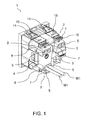
Fig. 1 is a perspective view of an electrical apparatus according to a currently preferred embodiment, where the electrical apparatus comprises three spring connection terminals, one of which is connected with two electrical conductors that are partially represented in this figure; -
Fig. 2 is a perspective view of a part of the electrical apparatus ofFig. 1 showing two spring connection terminals where these connection terminals are represented in two different configurations and where some parts of the electrical apparatus have been removed; -
Fig. 3 is a perspective view of a part of the electrical apparatus ofFig. 1 with further parts removed with respect toFig. 2 , which shows one of the connection terminals ofFig. 2 , and where an electrical conductor is partially shown in a phase of insertion into the connection terminal; -
Fig. 4 is a perspective view of a part of the electrical apparatus ofFig. 1 with some parts removed, which shows the connection terminal ofFig. 3 with an electrical conductor completely inserted into the terminal and in which the connection terminal is shown in a different configuration with respect toFig. 3 ; -
Fig. 5 is a perspective view of a part of the electrical apparatus ofFig. 1 with some parts removed, which shows the connection terminal ofFig. 3 with an electrical conductor completely inserted into the terminal and in which the connection terminal is shown in a different configuration with respect toFig. 4 ; -
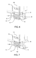
Fig. 6 is a perspective view that shows the connection terminal ofFig. 3 viewed from a different angle with respect toFig. 3 and represented in the configuration ofFig. 1 ; -
Fig. 7 is a perspective view similar toFig. 6 , in which the connection terminal is represented in the configuration ofFig. 5 ; -
Fig. 8 is a plan sectional view that shows the connection terminal ofFig. 3 in the configuration ofFig. 5 ; -
Fig. 9 is a perspective view of a part of the electrical apparatus ofFig. 1 that shows the connection terminal ofFig. 3 without an electrical conductor inserted into the terminal and where further parts of the electrical apparatus have been removed with respect toFig. 3 . - In the annexed figures, equal or similar elements will be indicated by the same reference numbers.
-
Fig. 1 shows an electrical apparatus that is globally indicated withreference number 1. In the example, theapparatus 1 is anelectrical socket 1 intended to be installed in a wall, preferably inside a wall box. It should be noted, however, that the teachings of the present description can be applied to any electronic or electromechanical apparatus suitable to be connected with rigid and/or flexible electrical cables such as, for example and not limited to, push button electrical switches or electrical sockets suitable to be installed in a wall, command devices for roller shutters, lamps, etc. - The
electrical socket 1 comprises a plurality ofspring connection terminals 2 according to a currently preferred embodiment. In the example, theconnection terminals 2 are so-calledautomatic terminals 2. In the example, thesocket 1 comprises, in particular, threespring connection terminals 2. It should be noted, anyway, that an electrical apparatus according to the teachings of this description may comprise, in general, one or more spring connection terminals. It should also be noted that, since the threeterminals 2 in the example are equal to each other, in the rest of this description, the structure and operation of theconnection terminals 2 will be described with reference to only one of theconnection terminals 2. - With cross reference to
Fig. 1 andFig. 2 , theconnection terminal 2 comprises alocking spring 3 that is housed in acase 4 made of electrically insulating material of theelectrical socket 1. In other words, thecase 4 of the electrical socket is, in the example, also thecase 4 made of electrically insulating material of theconnection terminal 2. As can be seen inFig. 1 , thecase 4 preferably has a generally box-shaped conformation. - The
locking spring 3 is a leaf spring provided to block at least one electrical conductor W1, such as a rigid electrical cable W1 or a flexible electrical cable (not shown), once the conductor has been inserted into aconductor aperture 5 provided on thecase 4. In practice, in known manner, thelocking spring 3 is provided to block the electrical conductor W1 so as to establish an electrical connection between the conductor W1 and theterminal 2. As is known, theconductor aperture 5 is provided to allow the insertion of the electrical conductor W1 in theterminal 2. In accordance with a preferred embodiment, thecase 4 of theconnection terminal 2 has a pair ofconductor apertures 5 and thelocking spring 3 comprises a pair of blockingportions 6, or blockingarms 6. The blockingarms 6 are adjacent to each other and are each associated with arespective conductor aperture 5. In this way, as can be seen inFig. 1 , theconnection terminal 2 allows to simultaneously block a pair of electrical conductors W1. In particular, according to a preferred embodiment, each conductor W1 is blocked between one of thearms 6 and a respectiveelectrical contact portion 22, of known type, of theterminal 2. - The
connection terminal 2 includes anactuation lever 7 suitable to cooperate with thelocking spring 3 to allow the insertion of the electrical conductor W1 in theterminal 2. Thelever 7 is suitable to selectively assume an operative position (Fig. 1 ,Fig.2 ,Fig. 3 ,Fig. 4 ,Fig. 6 andFig. 9 ) and a rest position (Fig. 5 ,Fig. 7 andFig. 8 ). In particular, thelever 7 is selectively movable in a sliding manner between the operative position (for example,Fig. 4 orFig. 6 ) and the rest position (for example,Fig. 5 orFig. 7 ). As can be seen from the accompanying figures, according to a preferred embodiment, thelever 7 is mounted or connected to thecase 4 so as to be selectively movable in a sliding manner between the operative position (for example,Fig. 4 orFig. 6 ) and the rest position (for example,Fig. 5 orFig. 7 ). In the operative position of thelever 7, it is possible to wire thesocket 1. In particular, in the operative position, theoperating lever 7 can rotate around an axis of rotation between a first angular position and a second angular position, which are distinct from each other. According a preferred embodiment, the first angular position is an angular insertion position (Fig. 2, Fig.3 andFig. 9 ), in which thelever 7 elastically deforms thelocking spring 3 to allow the insertion of the electrical conductor W1 in theterminal 2. Preferably, the second angular position is, instead, an angular position for locking (Fig. 1 ,Fig. 4 andFig. 6 ) in which thelever 7 is arranged in such a way as to allow thelocking spring 3 to block the electrical conductor W1 inserted in theterminal 2. With reference, for example, toFig. 3 , in the angular insertion position, thelever 7 elastically deforms thelocking spring 3 to allow the insertion of the electrical conductor W1 in theterminal 2. Preferably, thelever 7 elastically deforms thelocking spring 3 via a respective projecting thrust portion 21 (Fig. 9 ). In the angular blocking position the actuation lever is arranged in such a way as to allow the locking spring to block the electrical conductor W1 inserted in theterminal 2. In this regard, it should be noted that, for the purposes of this description, the expression "angular blocking position" is used indifferently to indicate the position taken inFig. 1 by thelever 7 of each of the threeconnection terminals 2 shown in this figure. It should be noted, however, that, as will be explained later when describing an exemplifying method ofwiring terminal 2, the angular blocking position of thelever 7 will, in practice, be slightly different depending on the number of conductors W1 inserted in theterminal 2. - According to a preferred embodiment, the
connection terminal 2 comprises a pair ofinhibition elements 8 provided or arranged to prevent rotation of thelever 7 in a first direction when thelever 7 assumes the rest position (Fig. 5 ). It should be noted that, in general, it is however enough to provide at least oneinhibition element 8 in theconnection terminal 2. According to a preferred embodiment, theinhibition elements 8 prevent the rotation of the lever towards thelocking spring 3. According to a preferred embodiment, theinhibition elements 8 comprise a pair ofstop elements 8, preferably a pair ofstop projections 8, which are opposite with respect to theactuation lever 7. Furthermore, thelever 7 preferably comprises a pair of projectinglateral rims 9 against which thestop elements 8 are suitable to abut. In other words, as can be seen, for example, inFig. 6, Fig. 7 orFig. 9 , according to a preferred embodiment, thelever 7 preferably comprises a pair of projectinglateral rims 9 that project laterally from the lever 7 (i.e., that project in the direction of the axis of rotation of the lever 7) and against which theinhibition elements 8 are suitable to abut. According to a preferred embodiment, thelever 7 comprises a projectingactuation portion 10 that preferably comprises thelateral projecting rims 9. Thisactuation portion 10 is a plate-shaped portion having anactuation face 11 adapted to be pressed with a finger in order to make theactuation lever 7 assume the angular insertion position. - According to a preferred embodiment, the
connection terminal 2 comprises at least one locking element 12 (Fig. 3 ,Fig. 8 ) which is suitable to cooperate with thelever 7 to block or impede selectively in a releasable manner the sliding of theactuation lever 7 between the operative position and the rest position. In particular, according to a preferred embodiment, the lockingelement 12 comprises at least one lockingtooth 12 operatively interposed between the operative position and the rest position of thelever 7. Furthermore, thelever 7 comprises a rotation shaft 13 (Fig. 9 ), orrotation pin 13, to allow the lever to rotate around said axis of rotation. Therotation shaft 13 is such as to act in contrast with the lockingtooth 12 when the operating lever slides between the operative position and the rest position so as to allow triggering theactuation lever 7 in the operative and rest positions in which the sliding of thelever 7 is blocked. In the example, theconnection terminal 2 comprises a pair of lockingteeth 12 which are located on two opposite sides of thelever 7. It should be noted that, according to a preferred embodiment, to allow the translatory movement of thelever 7 between the operative position and the rest position, thelever 7 comprises a guide portion 30 (Fig. 9 ) which is slidably mounted inside a guide slot 31 (Fig. 5 ) preferably provided on thecase 4. Moreover, always to allow the sliding of thelever 7, for example, with reference toFig. 5 , according to a preferred embodiment, in thecase 4 are provided a pair of shaft slots 32 (which are preferably slots having an open end) in which theshaft 13 can slide. - According to a preferred embodiment, the
case 4 comprises acase wall 14 facing to thelever 7 and which is arranged in such a way as to prevent thelever 7 from rotating in a second direction, opposite to the first direction mentioned above, when the lever assumes the angular blocking position. As can be seen, for example, inFig. 5 andFig. 8 , according to a preferred embodiment, in the rest position of theactuation lever 7, the projectingactuation portion 10 is arranged in an intermediate position between thecase wall 14 and the pair ofstop elements 8. Preferably, thecase wall 14 is provided with arelease aperture 15 through which a tool can be inserted, such as a screwdriver, to allow releasing thelever 7 when it assumes the rest position. According to a preferred embodiment, to reduce possible play between thelever 7 and thewall 14 when thelever 7 assumes the rest position, between thelever 7 and thewall 14, one or more play reduction elements 35 (Fig. 9 ) may be provided to allow more stable blocking of thelever 7. For example, these play reduction elements can include anengagement aperture 35 provided on thelever 7 to which an engagement tooth (not shown), projecting from thewall 14, can be removably engaged when thelever 7 assumes the rest position. Alternatively, according to an embodiment not shown in the figures, a projecting element can be provided on thelever 7, suitable to interfere by friction with thewall 14 when thelever 7 assumes the rest position. - After the above description of the structure of a spring connection terminal, an exemplifying method of connection of an electrical conductor to this terminal will now be described with reference to the embodiment illustrated in the annexed figures.
- In this regard, the
connection terminal 2 it is considered initially in the configuration ofFig. 1 in the case in which there are no electrical conductors W1 inserted in the terminal. In this configuration, theactuation lever 7 is in the operative position and assumes the angular blocking position (Fig. 1 ). In this configuration, a rotation of thelever 7 toward thewall 14 is prevented bysuch wall 14. Starting from this configuration, by pressing on theactuation face 11 of thelever 7, it is possible to make thelever 7 assume the angular insertion position (Fig. 2, Fig. 3 andFig. 9 ), contrasting the elastic reaction of thelocking spring 3. In particular, during the rotation of the actuation lever, the projectingthrust portion 21 acts on thelocking spring 3, and, more particularly, on the blockingarms 6, elastically deforming such spring. Once thelever 7 assumes the angular insertion position, it is possible to easily insert one or two electric conductors W1 through therespective conductor apertures 5 provided in thecase 4 while maintaining the pressure on theactuation face 11 of thelever 7. At this point, if the pressure on thelever 7 is released, the lockingspring 3 again bringslever 7 back to the angular blocking position (Fig. 1 ) by acting on thethrust portion 21 of thelever 7. - At the same time, the locking
spring 3 blocks the electrical conductors W1 between the blockingarms 6 and the respective portions of theelectrical connection 22 in order to establish the electrical connection between the conductors W1 and theterminal 2. - As mentioned above, it should be noted that the angular position of the
lever 7 in the angular blocking position will, in practice, be slightly different depending on the number of conductors W1 inserted in theterminal 2. In fact, if two conductors W1 have been inserted in theterminal 2, when releasing the pressure on thelever 7 starting from the said angular insertion position, thelever 7 does not return to exactly the same angular position as the lever had initially, when no conductor W1 was inserted into theterminal 2. In fact, since thelever 7 is pushed back by the twoarms 6 of the locking spring, if both are engaged for locking a respective conductor W1, then thelever 7 will return back slightly less. Conversely, if no conductor W1 is inserted into theterminal 2, by releasing the pressure on thelever 7 from the angular insertion position, thelever 7 will return exactly in the initial angular position. Similarly, if only one conductor W1 is inserted in theterminal 2, by releasing the pressure on thelever 7 from the angular insertion position, thelever 7 will return exactly in the initial angular position as the lockingarm 6, which is not engaged to block the conductor, will return exactly to the initial position also bringing thelever 7 back to the initial position by acting on thethrust portion 21 of the lever itself. - Once the conductors W1 are blocked, the
actuation lever 7 can be moved in a sliding manner, by pushing it until it assumes the rest position. This can be done, for example, by grasping the projectingactuation portion 10 with two fingers positioned respectively on theactuation face 11 and on a face of theactuation portion 10 that is opposite theactuation face 11. During the sliding of thelever 7, therotation shaft 13 acts in contrast with the lockingteeth 12 elastically deforming theseteeth 12 and/or the insulatingcase 4 until thelever 7 snaps into the rest position (Fig. 5 ,Fig. 7 andFig. 8 ). In other words, during the sliding of thelever 7, therotation shaft 13 engages or contacts the lockingteeth 12 elastically deforming theseteeth 12 and/or the insulatingcase 4 until thelever 7 snaps into the rest position (Fig. 5 ,Fig. 7 andFig. 8 ). After reaching the rest position, the rotation of thelever 7 towards the locking spring is prevented by thestop projections 8. Moreover, in the rest position, the sliding of thelever 7 towards the operative position is restricted by the lockingteeth 12. In this sense, the sliding of thelever 7 is blocked in a releasable manner in the rest position. In other words, thelever 7 can be brought back to the operative position by pulling thelever 7, for example by grasping the projectingportion 10, so as to slide it towards that position. During such sliding, therotation shaft 13 again counteracts the action of the lockingteeth 12 until thelever 7 snaps into the operative position. - Based on the above, it is therefore possible to understand how a spring connection terminal according to this description allows achieving the purposes mentioned above with reference to the state of the prior art.
- Conveniently, the fact of providing an actuation lever slidable between an operative position and a rest position and at least one inhibition element provided to prevent a rotation of the lever when the lever assumes the rest position, allows avoiding or reducing accidental actuation of the locking spring, thus ensuring particularly secure and reliable connection between the electrical conductor and the connection terminal.
Claims (10)
- Spring connection terminal (2) for an electrical apparatus (1), said terminal (2) comprising:- a case (4) in electrically insulated material having a conductor aperture (5) provided to permit the insertion of an electric conductor (W1) in said terminal (2);- a locking spring (3) housed in said case (4), the locking spring (3) being a leaf spring provided to block the electric conductor (W1) inserted in the conductor aperture (5) so as to establish an electric connection between the electric conductor (W1) and said terminal (2) ;- an actuation lever (7) adapted to cooperate with the locking spring (3) to permit the insertion of the electric conductor in said terminal, said lever (7) being adapted to assume an operating position in which said lever (7) can rotate around a rotation axis between a first angular position and second angular position different from each other,said terminal (2) being characterised in that it comprises at least one inhibition element (8) provided to prevent a rotation of said lever (7) in a first direction, said lever (7) being adapted to assume a rest position in which the rotation of the actuation lever (7) in said first direction is prevented by said at least one inhibition element (8) and said lever (7) being selectively movable in a sliding manner between said operating position and said rest position.
- Spring connection terminal (2) according to claim 1, wherein said first angular position is an angular insertion position in which said lever (7) elastically deforms the locking spring (3) to permit the insertion of the electric conductor (W1) in said terminal (2), and wherein said second angular position is an angular locking position in which said lever (7) is positioned so as to allow the locking spring (3) to block said electric conductor (W1) inserted in the terminal (2).
- Spring connection terminal (2) according to claim 1 or 2, wherein said at least one inhibition element (8) prevents the rotation of the actuation lever (7) towards the locking spring (3).
- Spring connection terminal (2) according to any of the previous claims, comprising at least one locking element (12) adapted to cooperate with said lever (7) to selectively and releasably block the sliding of said actuation lever (7) between the operating position and the rest position.
- Spring connection terminal (2) according to claim 4, wherein said locking element (12) comprises a locking tooth (12) operatively interposed between the operating position and the rest position, and wherein the lever (7) comprises a rotation shaft (13) to enable the actuation lever (7) to rotate around said rotation axis, the rotation shaft (13) being such as to act in contrast with the locking tooth (12) when the actuation lever (7) slides between the operating position and the rest position so as to make it possible to make the actuation lever (7) snap into said operating and rest positions in which the sliding of said lever is blocked.
- Spring connection terminal (2) according to any of the previous claims, wherein the actuation lever (7) comprises a pair of projecting lateral rims (9) and wherein said at least one inhibition element (8) comprises a pair of stop elements (8) positioned opposite the actuation lever (7) against which said projecting lateral rims (9) are adapted to abut.
- Spring connection terminal (2) according to claim 6, comprising a projecting actuation portion (10) which includes said projecting lateral rims (9), the actuation portion being a plate-shaped portion (10) having an actuation face (11) adapted to be pressed with a finger to make the actuation lever (7) assume the first angular position.
- Spring connection terminal (2) according to any of the previous claims, wherein said case (4) comprises a case wall (14) facing the actuation lever (7)and which is positioned so as to prevent said lever (7) from rotating in a second direction, opposite said first direction, when the actuation lever assumes the second angular position.
- Spring connection terminal (2) according to claim 8 inasmuch as dependent on claim 7, wherein in the rest position of the actuation lever (7), the projecting actuation portion (10) is arranged in an intermediate position between said case wall (14) and said pair of stop elements (8).
- Electric apparatus (1) according to any of the previous claims, comprising a spring connection terminal (2) as defined in any of the previous claims.
Applications Claiming Priority (1)
| Application Number | Priority Date | Filing Date | Title |
|---|---|---|---|
| IT000725A ITRM20130725A1 (en) | 2013-12-30 | 2013-12-30 | TERMINAL OF SPRING CONNECTION WITH DRIVE LEVER |
Publications (2)
| Publication Number | Publication Date |
|---|---|
| EP2889964A1 true EP2889964A1 (en) | 2015-07-01 |
| EP2889964B1 EP2889964B1 (en) | 2018-03-21 |
Family
ID=50190596
Family Applications (1)
| Application Number | Title | Priority Date | Filing Date |
|---|---|---|---|
| EP14200432.4A Active EP2889964B1 (en) | 2013-12-30 | 2014-12-29 | Spring connection terminal with actuation lever |
Country Status (3)
| Country | Link |
|---|---|
| EP (1) | EP2889964B1 (en) |
| ES (1) | ES2674219T3 (en) |
| IT (1) | ITRM20130725A1 (en) |
Cited By (3)
| Publication number | Priority date | Publication date | Assignee | Title |
|---|---|---|---|---|
| FR3062526A1 (en) * | 2017-02-02 | 2018-08-03 | Hager-Electro Sas | DEVICE FOR CONNECTING A DRIVER |
| CN109713463A (en) * | 2018-11-07 | 2019-05-03 | 苏州华旃航天电器有限公司 | A kind of quick locking wire electric connector |
| GB2629636A (en) * | 2023-05-05 | 2024-11-06 | Honeywell Int Inc | An electrical socket assembly and methods of installation and assembly |
Citations (5)
| Publication number | Priority date | Publication date | Assignee | Title |
|---|---|---|---|---|
| JP2000306618A (en) * | 1999-04-23 | 2000-11-02 | Matsushita Electric Works Ltd | Quick connection terminal device |
| US20050098419A1 (en) * | 2003-11-10 | 2005-05-12 | Yazaki Corporation | Lever fitting-type power supply circuit breaker |
| EP2355249A1 (en) * | 2010-02-01 | 2011-08-10 | Schneider Electric Industries SAS | Elastic clamp connecting terminal with lever |
| US20110223795A1 (en) * | 2008-08-27 | 2011-09-15 | Phoenix Contact Gmbh & Co. Kg | Electrical connection terminal |
| DE102012005465B3 (en) * | 2012-03-20 | 2013-05-08 | Wieland Electric Gmbh | spring clip |
-
2013
- 2013-12-30 IT IT000725A patent/ITRM20130725A1/en unknown
-
2014
- 2014-12-29 ES ES14200432.4T patent/ES2674219T3/en active Active
- 2014-12-29 EP EP14200432.4A patent/EP2889964B1/en active Active
Patent Citations (5)
| Publication number | Priority date | Publication date | Assignee | Title |
|---|---|---|---|---|
| JP2000306618A (en) * | 1999-04-23 | 2000-11-02 | Matsushita Electric Works Ltd | Quick connection terminal device |
| US20050098419A1 (en) * | 2003-11-10 | 2005-05-12 | Yazaki Corporation | Lever fitting-type power supply circuit breaker |
| US20110223795A1 (en) * | 2008-08-27 | 2011-09-15 | Phoenix Contact Gmbh & Co. Kg | Electrical connection terminal |
| EP2355249A1 (en) * | 2010-02-01 | 2011-08-10 | Schneider Electric Industries SAS | Elastic clamp connecting terminal with lever |
| DE102012005465B3 (en) * | 2012-03-20 | 2013-05-08 | Wieland Electric Gmbh | spring clip |
Cited By (4)
| Publication number | Priority date | Publication date | Assignee | Title |
|---|---|---|---|---|
| FR3062526A1 (en) * | 2017-02-02 | 2018-08-03 | Hager-Electro Sas | DEVICE FOR CONNECTING A DRIVER |
| EP3358679A1 (en) * | 2017-02-02 | 2018-08-08 | Hager-Electro Sas | Device for connecting a conductor |
| CN109713463A (en) * | 2018-11-07 | 2019-05-03 | 苏州华旃航天电器有限公司 | A kind of quick locking wire electric connector |
| GB2629636A (en) * | 2023-05-05 | 2024-11-06 | Honeywell Int Inc | An electrical socket assembly and methods of installation and assembly |
Also Published As
| Publication number | Publication date |
|---|---|
| ES2674219T3 (en) | 2018-06-28 |
| ITRM20130725A1 (en) | 2015-07-01 |
| EP2889964B1 (en) | 2018-03-21 |
Similar Documents
| Publication | Publication Date | Title |
|---|---|---|
| US8137145B2 (en) | Wiring termination mechanisms and use thereof | |
| US7963812B2 (en) | Wire termination apparatus and method | |
| US7909664B2 (en) | Wire termination apparatus and method | |
| US7766689B2 (en) | Plug adapter for an electrical switching device | |
| CN102856727B (en) | For the actuator of junctor | |
| US11316288B2 (en) | Electrical connector with slider operated clamp spring arm | |
| JP6583323B2 (en) | Wiring connector and electrical equipment | |
| CN102195145A (en) | Flexible connection terminal with an operation lever | |
| HK1250423A1 (en) | Electrical power distribution device | |
| WO2011068113A1 (en) | Connection terminal device | |
| EP2889964B1 (en) | Spring connection terminal with actuation lever | |
| CA2958212C (en) | Electrical connector having poke-in wire contacts | |
| AU2014272971A1 (en) | Electrical connection system with automatic closing | |
| CN106575840A (en) | Plug adapter for electronic device for plugging in power cord and system formed by plug adapter and device | |
| JP6648046B2 (en) | Connected equipment | |
| CN109818220B (en) | Electrical system comprising an electrical unit and an interchangeable connection module | |
| US10014595B2 (en) | Connector assembly for an electrical device | |
| US7431603B1 (en) | Electrical wire connector | |
| US20250183561A1 (en) | Connection terminal for conductors | |
| EP3813087A1 (en) | In-line switch assembly | |
| CN112470343A (en) | Test plug block and test terminal block | |
| CN210074175U (en) | line protection device | |
| CN204632710U (en) | Insurance module | |
| US20240213693A1 (en) | Connection device and method for installing such a connection device | |
| JP7477611B2 (en) | Connection device for shield conductors of power transmission lines |
Legal Events
| Date | Code | Title | Description |
|---|---|---|---|
| PUAI | Public reference made under article 153(3) epc to a published international application that has entered the european phase |
Free format text: ORIGINAL CODE: 0009012 |
|
| 17P | Request for examination filed |
Effective date: 20141229 |
|
| AK | Designated contracting states |
Kind code of ref document: A1 Designated state(s): AL AT BE BG CH CY CZ DE DK EE ES FI FR GB GR HR HU IE IS IT LI LT LU LV MC MK MT NL NO PL PT RO RS SE SI SK SM TR |
|
| AX | Request for extension of the european patent |
Extension state: BA ME |
|
| R17P | Request for examination filed (corrected) |
Effective date: 20151230 |
|
| RBV | Designated contracting states (corrected) |
Designated state(s): AL AT BE BG CH CY CZ DE DK EE ES FI FR GB GR HR HU IE IS IT LI LT LU LV MC MK MT NL NO PL PT RO RS SE SI SK SM TR |
|
| GRAP | Despatch of communication of intention to grant a patent |
Free format text: ORIGINAL CODE: EPIDOSNIGR1 |
|
| RIC1 | Information provided on ipc code assigned before grant |
Ipc: H01R 13/629 20060101ALN20171003BHEP Ipc: H01R 4/48 20060101AFI20171003BHEP Ipc: H01R 9/26 20060101ALI20171003BHEP |
|
| INTG | Intention to grant announced |
Effective date: 20171107 |
|
| GRAS | Grant fee paid |
Free format text: ORIGINAL CODE: EPIDOSNIGR3 |
|
| GRAA | (expected) grant |
Free format text: ORIGINAL CODE: 0009210 |
|
| AK | Designated contracting states |
Kind code of ref document: B1 Designated state(s): AL AT BE BG CH CY CZ DE DK EE ES FI FR GB GR HR HU IE IS IT LI LT LU LV MC MK MT NL NO PL PT RO RS SE SI SK SM TR |
|
| REG | Reference to a national code |
Ref country code: GB Ref legal event code: FG4D |
|
| REG | Reference to a national code |
Ref country code: CH Ref legal event code: EP |
|
| REG | Reference to a national code |
Ref country code: AT Ref legal event code: REF Ref document number: 982038 Country of ref document: AT Kind code of ref document: T Effective date: 20180415 |
|
| REG | Reference to a national code |
Ref country code: IE Ref legal event code: FG4D |
|
| REG | Reference to a national code |
Ref country code: DE Ref legal event code: R096 Ref document number: 602014022562 Country of ref document: DE |
|
| REG | Reference to a national code |
Ref country code: ES Ref legal event code: FG2A Ref document number: 2674219 Country of ref document: ES Kind code of ref document: T3 Effective date: 20180628 |
|
| REG | Reference to a national code |
Ref country code: NL Ref legal event code: MP Effective date: 20180321 |
|
| PG25 | Lapsed in a contracting state [announced via postgrant information from national office to epo] |
Ref country code: CY Free format text: LAPSE BECAUSE OF FAILURE TO SUBMIT A TRANSLATION OF THE DESCRIPTION OR TO PAY THE FEE WITHIN THE PRESCRIBED TIME-LIMIT Effective date: 20180321 Ref country code: FI Free format text: LAPSE BECAUSE OF FAILURE TO SUBMIT A TRANSLATION OF THE DESCRIPTION OR TO PAY THE FEE WITHIN THE PRESCRIBED TIME-LIMIT Effective date: 20180321 Ref country code: NO Free format text: LAPSE BECAUSE OF FAILURE TO SUBMIT A TRANSLATION OF THE DESCRIPTION OR TO PAY THE FEE WITHIN THE PRESCRIBED TIME-LIMIT Effective date: 20180621 Ref country code: LT Free format text: LAPSE BECAUSE OF FAILURE TO SUBMIT A TRANSLATION OF THE DESCRIPTION OR TO PAY THE FEE WITHIN THE PRESCRIBED TIME-LIMIT Effective date: 20180321 Ref country code: HR Free format text: LAPSE BECAUSE OF FAILURE TO SUBMIT A TRANSLATION OF THE DESCRIPTION OR TO PAY THE FEE WITHIN THE PRESCRIBED TIME-LIMIT Effective date: 20180321 |
|
| REG | Reference to a national code |
Ref country code: LT Ref legal event code: MG4D |
|
| REG | Reference to a national code |
Ref country code: AT Ref legal event code: MK05 Ref document number: 982038 Country of ref document: AT Kind code of ref document: T Effective date: 20180321 |
|
| PG25 | Lapsed in a contracting state [announced via postgrant information from national office to epo] |
Ref country code: SE Free format text: LAPSE BECAUSE OF FAILURE TO SUBMIT A TRANSLATION OF THE DESCRIPTION OR TO PAY THE FEE WITHIN THE PRESCRIBED TIME-LIMIT Effective date: 20180321 Ref country code: LV Free format text: LAPSE BECAUSE OF FAILURE TO SUBMIT A TRANSLATION OF THE DESCRIPTION OR TO PAY THE FEE WITHIN THE PRESCRIBED TIME-LIMIT Effective date: 20180321 Ref country code: BG Free format text: LAPSE BECAUSE OF FAILURE TO SUBMIT A TRANSLATION OF THE DESCRIPTION OR TO PAY THE FEE WITHIN THE PRESCRIBED TIME-LIMIT Effective date: 20180621 Ref country code: RS Free format text: LAPSE BECAUSE OF FAILURE TO SUBMIT A TRANSLATION OF THE DESCRIPTION OR TO PAY THE FEE WITHIN THE PRESCRIBED TIME-LIMIT Effective date: 20180321 Ref country code: GR Free format text: LAPSE BECAUSE OF FAILURE TO SUBMIT A TRANSLATION OF THE DESCRIPTION OR TO PAY THE FEE WITHIN THE PRESCRIBED TIME-LIMIT Effective date: 20180622 |
|
| PG25 | Lapsed in a contracting state [announced via postgrant information from national office to epo] |
Ref country code: EE Free format text: LAPSE BECAUSE OF FAILURE TO SUBMIT A TRANSLATION OF THE DESCRIPTION OR TO PAY THE FEE WITHIN THE PRESCRIBED TIME-LIMIT Effective date: 20180321 Ref country code: RO Free format text: LAPSE BECAUSE OF FAILURE TO SUBMIT A TRANSLATION OF THE DESCRIPTION OR TO PAY THE FEE WITHIN THE PRESCRIBED TIME-LIMIT Effective date: 20180321 Ref country code: NL Free format text: LAPSE BECAUSE OF FAILURE TO SUBMIT A TRANSLATION OF THE DESCRIPTION OR TO PAY THE FEE WITHIN THE PRESCRIBED TIME-LIMIT Effective date: 20180321 Ref country code: PL Free format text: LAPSE BECAUSE OF FAILURE TO SUBMIT A TRANSLATION OF THE DESCRIPTION OR TO PAY THE FEE WITHIN THE PRESCRIBED TIME-LIMIT Effective date: 20180321 Ref country code: AL Free format text: LAPSE BECAUSE OF FAILURE TO SUBMIT A TRANSLATION OF THE DESCRIPTION OR TO PAY THE FEE WITHIN THE PRESCRIBED TIME-LIMIT Effective date: 20180321 |
|
| PG25 | Lapsed in a contracting state [announced via postgrant information from national office to epo] |
Ref country code: SM Free format text: LAPSE BECAUSE OF FAILURE TO SUBMIT A TRANSLATION OF THE DESCRIPTION OR TO PAY THE FEE WITHIN THE PRESCRIBED TIME-LIMIT Effective date: 20180321 Ref country code: AT Free format text: LAPSE BECAUSE OF FAILURE TO SUBMIT A TRANSLATION OF THE DESCRIPTION OR TO PAY THE FEE WITHIN THE PRESCRIBED TIME-LIMIT Effective date: 20180321 Ref country code: SK Free format text: LAPSE BECAUSE OF FAILURE TO SUBMIT A TRANSLATION OF THE DESCRIPTION OR TO PAY THE FEE WITHIN THE PRESCRIBED TIME-LIMIT Effective date: 20180321 Ref country code: CZ Free format text: LAPSE BECAUSE OF FAILURE TO SUBMIT A TRANSLATION OF THE DESCRIPTION OR TO PAY THE FEE WITHIN THE PRESCRIBED TIME-LIMIT Effective date: 20180321 |
|
| PG25 | Lapsed in a contracting state [announced via postgrant information from national office to epo] |
Ref country code: PT Free format text: LAPSE BECAUSE OF FAILURE TO SUBMIT A TRANSLATION OF THE DESCRIPTION OR TO PAY THE FEE WITHIN THE PRESCRIBED TIME-LIMIT Effective date: 20180723 |
|
| REG | Reference to a national code |
Ref country code: DE Ref legal event code: R097 Ref document number: 602014022562 Country of ref document: DE |
|
| PLBE | No opposition filed within time limit |
Free format text: ORIGINAL CODE: 0009261 |
|
| STAA | Information on the status of an ep patent application or granted ep patent |
Free format text: STATUS: NO OPPOSITION FILED WITHIN TIME LIMIT |
|
| PG25 | Lapsed in a contracting state [announced via postgrant information from national office to epo] |
Ref country code: DK Free format text: LAPSE BECAUSE OF FAILURE TO SUBMIT A TRANSLATION OF THE DESCRIPTION OR TO PAY THE FEE WITHIN THE PRESCRIBED TIME-LIMIT Effective date: 20180321 |
|
| 26N | No opposition filed |
Effective date: 20190102 |
|
| PG25 | Lapsed in a contracting state [announced via postgrant information from national office to epo] |
Ref country code: SI Free format text: LAPSE BECAUSE OF FAILURE TO SUBMIT A TRANSLATION OF THE DESCRIPTION OR TO PAY THE FEE WITHIN THE PRESCRIBED TIME-LIMIT Effective date: 20180321 |
|
| REG | Reference to a national code |
Ref country code: CH Ref legal event code: PL |
|
| GBPC | Gb: european patent ceased through non-payment of renewal fee |
Effective date: 20181229 |
|
| PG25 | Lapsed in a contracting state [announced via postgrant information from national office to epo] |
Ref country code: LU Free format text: LAPSE BECAUSE OF NON-PAYMENT OF DUE FEES Effective date: 20181229 Ref country code: MC Free format text: LAPSE BECAUSE OF FAILURE TO SUBMIT A TRANSLATION OF THE DESCRIPTION OR TO PAY THE FEE WITHIN THE PRESCRIBED TIME-LIMIT Effective date: 20180321 |
|
| REG | Reference to a national code |
Ref country code: BE Ref legal event code: MM Effective date: 20181231 Ref country code: IE Ref legal event code: MM4A |
|
| PG25 | Lapsed in a contracting state [announced via postgrant information from national office to epo] |
Ref country code: IE Free format text: LAPSE BECAUSE OF NON-PAYMENT OF DUE FEES Effective date: 20181229 |
|
| PG25 | Lapsed in a contracting state [announced via postgrant information from national office to epo] |
Ref country code: BE Free format text: LAPSE BECAUSE OF NON-PAYMENT OF DUE FEES Effective date: 20181231 |
|
| PG25 | Lapsed in a contracting state [announced via postgrant information from national office to epo] |
Ref country code: CH Free format text: LAPSE BECAUSE OF NON-PAYMENT OF DUE FEES Effective date: 20181231 Ref country code: GB Free format text: LAPSE BECAUSE OF NON-PAYMENT OF DUE FEES Effective date: 20181229 Ref country code: LI Free format text: LAPSE BECAUSE OF NON-PAYMENT OF DUE FEES Effective date: 20181231 |
|
| PG25 | Lapsed in a contracting state [announced via postgrant information from national office to epo] |
Ref country code: MT Free format text: LAPSE BECAUSE OF NON-PAYMENT OF DUE FEES Effective date: 20181229 |
|
| PG25 | Lapsed in a contracting state [announced via postgrant information from national office to epo] |
Ref country code: TR Free format text: LAPSE BECAUSE OF FAILURE TO SUBMIT A TRANSLATION OF THE DESCRIPTION OR TO PAY THE FEE WITHIN THE PRESCRIBED TIME-LIMIT Effective date: 20180321 |
|
| PG25 | Lapsed in a contracting state [announced via postgrant information from national office to epo] |
Ref country code: HU Free format text: LAPSE BECAUSE OF FAILURE TO SUBMIT A TRANSLATION OF THE DESCRIPTION OR TO PAY THE FEE WITHIN THE PRESCRIBED TIME-LIMIT; INVALID AB INITIO Effective date: 20141229 Ref country code: MK Free format text: LAPSE BECAUSE OF NON-PAYMENT OF DUE FEES Effective date: 20180321 |
|
| PG25 | Lapsed in a contracting state [announced via postgrant information from national office to epo] |
Ref country code: IS Free format text: LAPSE BECAUSE OF FAILURE TO SUBMIT A TRANSLATION OF THE DESCRIPTION OR TO PAY THE FEE WITHIN THE PRESCRIBED TIME-LIMIT Effective date: 20180721 |
|
| PGFP | Annual fee paid to national office [announced via postgrant information from national office to epo] |
Ref country code: DE Payment date: 20241121 Year of fee payment: 11 |
|
| PGFP | Annual fee paid to national office [announced via postgrant information from national office to epo] |
Ref country code: FR Payment date: 20241121 Year of fee payment: 11 |
|
| PGFP | Annual fee paid to national office [announced via postgrant information from national office to epo] |
Ref country code: ES Payment date: 20250102 Year of fee payment: 11 |
|
| PGFP | Annual fee paid to national office [announced via postgrant information from national office to epo] |
Ref country code: IT Payment date: 20251119 Year of fee payment: 12 |